GEOTECHNICAL DATA REPORT
|
|
|
- Camilla Goodman
- 5 years ago
- Views:
Transcription


1 GEOTECHNICAL DATA REPORT STRUCTURE B-639 REPLACEMENT JACK CREEK BRIDGE ON SR 226 ELKO COUNTY, NEVADA NOVEMBER 2018
2 STATE OF NEVADA DEPARTMENT OF TRANSPORTATION MATERIALS DIVISION GEOTECHNICAL SECTION STRUCTURE B-639 REPLACEMENT JACK CREEK BRIDGE ON SR 226 ELKO COUNTY, NEVADA November 2018 EA Prepared by: Keith Conrad, P.E. Senior Geotechnical Engineer Reviewed by: Jeff Palmer, Ph.D., P.E. Principal Geotechnical Engineer Reviewed by: Mike Griswold, P.E. Chief Geotechnical Engineer Approved by: Darin Tedford, P.E. Chief Materials Engineer
3 Table of Contents 1.0 INTRODUCTION Project Location Project Description SCOPE OF WORK Purpose and Scope GEOLOGIC CONDITIONS AND SEISMICITY Geologic Setting Seismicity and Faulting Site Classification and Seismic Parameters FIELD INVESTIGATION Exploratory Borings Geophysical Site Investigation Laboratory Analysis FOUNDATION Structure Loads Construction Platform Geotextile Specifications Soil Bearing Resistance Settlement Wingwall Lateral Earth Pressure REFERENCES... 7 APPENDICES APPENDIX A.. Site Location Map Geology Map Earthquake Fault Map Borings and ReMi Location Map APPENDIX B.. Boring Log Key and Boring Logs APPENDIX C.. Laboratory Test Summary and Results APPENDIX D..Geophysical Test Results
4 1.0 INTRODUCTION 1.1 Project Location The Nevada Department of Transportation (NDOT) will be replacing the bridge structure B-639 on State Route 226, milepost EL32.70 to EL32.90, Elko County, Nevada. The bridge project location is in Township 42 North, Range 52 East, in the southwest quarter of Section 35, M.D.B.&M at coordinates 41 29'36" N, '60" W. The structure crosses over Jack Creek approximately one-eighth of a mile south of Jack Creek Road. 1.2 Project Description Structure B-639 was built in 1956 and was originally designed and built as a two-cell Reinforced Concrete Box (RCB) Culvert. According to the August 2016 Inspection Report, the bridge is in poor condition, with a sufficiency rating of As stated in the report, the culvert condition consists of large spalls, heavy scaling, wide cracks and considerable efflorescence. Opened construction joints permit the loss of backfill. Considerable misalignment exists, possibly due to settlement. Considerable scouring or erosion exists at curtain walls, wingwalls and pipes. Metal parts have significant distortion and deflection throughout, extensive corrosion and deep pitting. The project plan is to replace the existing RCB culvert structure with a larger RCB culvert structure. New and larger wing walls will be constructed on all four corners. The structure will continue to have the same length parallel to the road, which is skewed degrees relative to the creek. The completed bridge will continue to convey one lane of traffic in each direction over the waterway. The project includes removing and replacing the entire RCB culvert and wing walls. The final dimensions of the RCB culvert will be 86 feet long by feet wide. The completed structure will have an increased footprint and will retain the same road surface elevation as the current structure. 2.0 SCOPE OF WORK 2.1 Purpose and Scope The purpose of the work is to replace the current bridge structure with a new RCB culvert and wingwalls. The purpose of the geotechnical investigation is to provide data regarding the subsurface soil and groundwater conditions at the proposed bridge site and provide recommended geotechnical design values. The scope of the geotechnical investigation is to: review published maps and reports gather data from past field explorations and reports 1
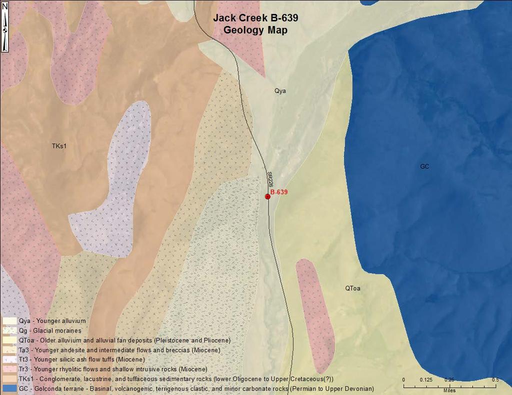
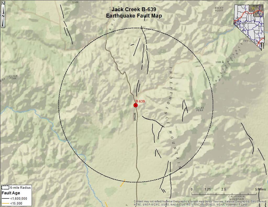
5 perform field reconnaissance conduct subsurface explorations consisting of two borings obtain soil samples from field tests analyze field and laboratory testing data. This report includes boring logs and summaries of test results from the field investigations and the laboratory testing regimen. The boring logs and summaries are in Appendices B and C. 3.0 GEOLOGIC CONDITIONS AND SEISMICITY 3.1 Geologic Setting The project site is in the Columbia Basin watershed and within the Basin and Range Province, which encompasses the majority of the State of Nevada. The Basin and Range province is generally composed of north-trending mountain ranges separated by alluvial, normal-fault bounded basins. Regionally, the project falls within a narrow valley alluvial deposit between the Tuscarora Mountains to the west and the Independence Mountains to the east. The site is in a narrow valley at the very north end of Independence Valley. The site is mapped as the Qya geologic unit (Quaternary Younger Alluvium). A geologic map is shown in Appendix A. Locally, the Qya geologic unit consist of many alluvial deposits emanating from the nearby mountains to the west and east. Surface exposure of the Qya geologic unit at the site shows an abundance of sub-round to round quartzite gravels, cobbles and boulders. Historic Jack Creek channel meander and erosion is somewhat limited within the narrow valley (approximately 600 wide) at the site location. This causes variability in the near surface soil deposits both laterally and vertically. 3.2 Seismicity and Faulting The Independence, Tuscarora and Bull Run Mountains contain numerous quaternary faults within a sixmile radius from the project site. These faults are comprised of the Eastern Independence Mountains Fault Zone and the Tuscarora Fault Zone. At the Tuscarora Fault Zone, the fault activity is older than 15,000 years. Most local faults are located at alluvial basin edges at the base of the mountains. An earthquake fault map of the area is in Appendix A. 3.3 Site Classification and Seismic Parameters The seismic provisions of the AASHTO LRFD Bridge Design Specifications (AASHTO) Article 3. are applied to bridge design in Nevada. Earthquake force effects were determined in accordance with AASHTO Article 3.. The seismic coefficients used must meet or exceed the minimum seismic coefficients shown in Figure 12.3-H of the NDOT Structures Manual. Three sets of coefficients are provided in the table below from 2
6 different sources for Elko County. We recommend using the NDOT coefficients, as they are the minimum allowed, to develop an acceleration response spectrum. PGA S s S 1 AASHTO USGS NDOT Minimum for Elko County from NDOT Structures Manual Table 1. Seismic Design Parameters AASHTO Article 3..1 recommends selecting peak ground acceleration (PGA) based on the horizontal peak ground acceleration coefficient with seven percent probability of exceedance in 75 years (approximately 0-year return period). The PGA, short-period response spectral acceleration (S S) and long-period response spectral accelerations (S 1) for the site were obtained using AASHTO figure , USGS U.S. Seismic Design Maps online tool (2009 AASHTO) and NDOT Structure Manual Figure 12.3-H. The site class for the project location is Site Class B (AASHTO Table ) based on V s, the average shear wave velocity. The average shear wave velocity was obtained utilizing the Refraction MicroTremor (ReMi TM ) geophysical testing method. ReMi TM V s results for the site were 2,821 feet per second. 4.0 FIELD INVESTIGATION 4.1 Exploratory Borings The NDOT Geotechnical Section performed a site investigation at the project site in September 2017 at the locations shown on the boring location map in Appendix A. The subsurface exploration consisted of two exploratory borings drilled with a Diedrich D-120 truck-mounted drill rig (NDOT #82) utilizing sixinch hollow-stem auger without drilling fluid. Soil samples and standard penetration resistance values (Nvalues) were obtained utilizing the Standard Penetration Test (SPT, ASTM D1586) and ring-lined Modified California Sampler (CMS, ASTM D3550). The uncorrected field blow counts are shown on the boring logs in Appendix B. The uncorrected blow counts have not been corrected for hammer energy, sampler type, rod length or hammer type. The Energy Transfer Ratio (ER) for NDOT #82 is 86%. Field CMS N-values are converted to field SPT N-values by a multiplication factor of 0.62, as stated in the Key to Boring Logs found in Appendix B. All soil samples were either classified using Unified Soil Classification System (USCS, ASTM D2487) laboratory testing or described and identified according to Visual-Manual Procedures (ASTM D2488). 3
7 The borings were made on the banks on both sides of the creek. No borings were made in the channel bottom, which is at a depth of eight to ten feet in the borings. It is possible that the channel soils are different from the soils in the boring logs. The soils encountered while drilling include medium dense to dense silty sand and silty sand with gravel. The water table in the boring logs are at a depth of 8 feet (elevation ) in boring 3S and 8.5 feet (elevation ) in boring 1N-2N. Below ten and one-half feet in boring 3S and nineteen and one-half feet in boring 1N-2N, the soils became too hard to sample and the down pressure required to drill increased from 300 psi to 500 psi. It is interpreted that this material is weak bedrock. 4.2 Geophysical Site Investigation Seismic Data Collection The ReMi TM seismic survey was performed using a twelve-geophone set with each geophone spaced 20 feet apart. The ReMi seismic line started near Boring 3S and ran along SR226 to the east, parallel to the road. See the map of seismic line layout in Appendix A. Background noise consisting of roadway traffic and walking the seismic line were used to generate seismic waves during the ReMi TM survey. The field exploration, noise data acquisition, location survey and preliminary data verification was performed by NDOT geotechnical staff. ReMi Seismic Data Analysis The analysis and interpretation of the seismic data collected for this project was performed by Optim, Incorporated of Reno, Nevada. Ten total 30-second data acquisition recordings were made and processed by Optim. The noise data collected for ReMi TM was analyzed using the proprietary SeisOpt ReMi TM software developed by Optim. See the geophysical test results in Appendix D. This plot depicts variation in the shear wave velocity profile to a depth of feet and provides the average shear wave velocity for the upper feet (Vs) of the soil profile. 4.3 Laboratory Analysis Laboratory analyses were performed on soil samples collected from the boreholes. The testing program consisted of sieve, hydrometer, specific gravity, Atterberg limits, moisture content and dry unit weights analyses. Test result summary information is presented in Appendix C. 5.0 FOUNDATION 5.1 Structure Loads Anticipated structure loads, including the wing walls, were provided by the NDOT Structures Division. The Service I load for the structure is 1.89 ksf and the Strength I load is 2.56 ksf. 4
8 5.2 Construction Platform The RCB culvert shall be bedded on 4 inches of Class C Bedding material (2017 NDOT Standard Plans, Drawing R-1.1.6) and backfilled in accordance with 2017 NDOT Standard Plans, Drawing R It is likely that unstable foundation conditions will be encountered during construction due to migration of saturated sands, seepage, and/or yielding conditions, which prevent proper compaction of the foundation soils. Therefore, both the RCB culvert and wingwall footings, including the 4 inches of Class C Bedding material, shall be founded on top of construction platforms consisting of Class 150 Riprap Bedding wrapped in Nonwoven Geotextile Class 1 fabric. The minimum thickness of the wrapped Riprap Bedding is 36 inches under the RCB culvert and 18 inches under the wingwalls. Place Riprap Bedding, for the construction platforms, in lifts and properly compact in accordance with Section 208. The initial lift of Riprap Bedding should be approximately 12 inches and following lifts should be no more than 8 inches. Locations and elevations of the construction platforms are depicted in the construction plans. 5.3 Geotextile Specifications NDOT Nonwoven Geotextile Class 1 as specified for the construction platforms shall be in conformance with Sections 203 and Soil Bearing Resistance Bearing resistances of the soil under the RCB culvert were analyzed using the entire structure founded on top of a forty-inch-thick sand layer and construction platform with elevation of 6128 feet. Bearing resistances of the soil under the structure and on top of the sand and construction platform, are summarized in Table 1 and are further explained in the following sections. Table 1. Reinforced Concrete Box Culvert Foundation Bearing Resistances Service Limit State Strength Limit State Extreme Limit State Factored Nominal Factored Nominal Resistance Resistance Resistance Resistance (ksf) (ksf) (ksf) (ksf) Nominal Resistance (ksf) Factored Resistance (ksf) Service Limit State The resistance factor for the service limit state shall be taken as 1.0 in accordance with AASHTO Article Therefore, nominal and factored resistances at the service limit states are equal. For this project, the factored bearing resistance at the Service I Limit State is defined as the net bearing pressure that is estimated to produce 1 inch of total settlement. Bearing resistance of the soil was calculated by using an elastic half-space settlement equation in accordance with AASHTO Article with the maximum allowed settlement of 1 inch for the 5
9 proposed RCB culvert. From the equation, this settlement would occur by applying a net bearing pressure of approximately 4 ksf. Therefore, the nominal and factored bearing resistances of the soil at the Service I Limit State are both 4 ksf. Strength Limit State Nominal bearing resistance at the Strength Limit State was calculated using the nominal bearing resistance equation in accordance with AASHTO Article a. The bearing resistance factor for the Strength Limit state is 0.45, which is used in our analysis based on the theoretical method, in sand, using SPT from AASHTO Table Therefore, the nominal bearing resistance at the Strength Limit State for the proposed RCB culvert is calculated to be 48 ksf, and the factored bearing resistance is 22 ksf. Extreme Event Limit State The bearing resistance factor for the Extreme Event Limit State is equal to 1.0 according to AASHTO Article.5.53 and is applicable to both scour and earthquake loading. The nominal bearing resistance at the Extreme Event Limit State is calculated to be 70 ksf, in accordance with AASHTO and the factored bearing resistance is also 70 ksf. 5.5 Settlement A settlement analyses for the RCB culvert on top of the sand layer and construction platform was made using the elastic half-space settlement equation with actual loads provided by NDOT Structures Division. Settlement analyses using computational methods based on the results of laboratory and in situ testing were performed in accordance with AASHTO Article The maximum total settlement calculated was 0.47 inches and consisted entirely of immediate settlement. Long term consolidation settlement was negligible. 5.6 Wingwall Lateral Earth Pressure The at-rest earth pressure coefficient Ko is 0.44 and equivalent fluid unit pressure is 53 pcf for horizontal backfill conditions for the wingwalls. These values are based on the assumption that the wingwalls will be backfilled with on-site excavated materials. These materials have soil strength parameters of friction angle of 34 degrees, a cohesion of 0 and a unit weight of 120 pcf in the calculations. Little movement is expected with the wingwalls and the following active and passive lateral wingwall pressure coefficients of Ka = 0.28 and Kp = 3.5 are appropriate for use. The total force is applied at one-third of the wall height. 6
10 6.0 REFERENCES 1. Seismic Hazards in the Reno-Carson City Urban Corridor: 2. Quaternary Fault and Fold Database of the United States (U.S. Geological Survey): 3. Hydrologic Data 4. Geologic Map of Elko County, Nevada 5. United State Geological Survey (USGS) Data Series 249: Geologic Map of Nevada (digital) 6. Geologic map of the Gardnerville Quadrangle, Elko County, Nevada; 1:24,000; Geologic map of the Freel Peak 15' quadrangle, California and Nevada; 1:62,500; Reconnaissance Surficial Geologic Map of the Mt. Siegel Quadrangle, Nevada - California; 1:62,500; United States Department of Agriculture Web Soil Survey (USDA-WSS). AASHTO LRFD Bridge Design Specifications, 8th Edition 11. NDOT Structures Manual NDOT Standard Plans 7
11 APPENDIX A: Site Location Map Geology Map Earthquake Fault Map Boring and ReMi Location Map

12 ³ Jack Creek B-639 Location Map B-639! Miles Content may not reflect National Geographic's current map policy. Sources: National Geographic, Esri, Garmin, HERE, UNEP-WCMC, USGS, NASA, ESA, METI, NRCAN, GEBCO, NOAA, increment P Corp.
13
14

15 Borings and ReMi Location Map 1N-2N 3S ReMi Geophone Locations Borehole Locations
16 APPENDIX B: Boring Log Key Boring Logs
17 KEY TO EXPLORATION LOGS PARTICLE SIZE LIMITS CLAY SILT SAND GRAVEL COBBLES BOULDERS FINE MEDIUM COARSE FINE COARSE.002 mm #200 #40 # #4 ¾ inch 3 inch 12 inch USCS GROUP GW GP GC SW SP SM SC ML CL OL MH CH OH PT TYPICAL SOIL DESCRIPTION Well graded gravels, gravel-sand mixtures, little or no fines Poorly graded gravels, gravel-sand mixtures, little or no fines Clayey gravels, poorly graded gravel-sand-clay mixtures Well graded sands, gravelly sands, little or no fines Poorly graded sands, gravelly sands, little or no fines Silty sands, poorly graded sand-silt mixtures Clayey sands, poorly graded sand-clay mixtures Inorganic silts and very fine sands, rock flour, silty or clayey fine sands with slight plasticity Inorganic clays of low to medium plasticity, gravelly clays, sandy clays, silty clays, lean clays Organic silts and organic silt-clays of low plasticity Inorganic silts, micaceous or diatomaceous fine sandy or silty soils, elastic silts Inorganic clays of high plasticity, fat clays Organic clays of medium to high plasticity Peat and other highly organic soils MOISTURE CONDITION CRITERIA SOIL CEMENTATION CRITERIA Description Criteria Description Criteria Dry Absence of moisture, dusty, Weak Crumbles or breaks with handling or little dry to touch. finger pressure. Moist Damp, no visible free water. Moderate Crumbles or breaks with considerable Wet Visible free water, usually below finger pressure. groundwater table. Strong Won t break or crumble w/finger pressure Ñ Groundwater Elevation Symbols TEST ABBREVIATIONS CD CONSOLIDATED DRAINED CH CHEMICAL (CORROSIVENESS) CM COMPACTION CU CONSOLIDATED UNDRAINED D DISPERSIVE SOILS DS DIRECT SHEAR E EXPANSIVE SOIL G SPECIFIC GRAVITY H HYDROMETER HC HYDRO-COLLAPSE K PERMEABILITY OC ORGANIC CONTENT C CONSOLIDATION PI PLASTICITY INDEX RQD ROCK QUALITY DESIGNATION RV R-VALUE S SIEVE ANALYSIS SL SHRINKAGE LIMIT U UNCONFINED COMPRESSION UU UNCONSOLIDATED UNDRAINED UW UNIT WEIGHT W MOISTURE CONTENT SOIL COLOR DESIGNATIONS ARE FROM THE MUNSELL SOIL/ROCK COLOR CHARTS. EXAMPLE: Revised August 20 STANDARD PENETRATION CLASSIFICATION * GRANULAR SOIL CLAYEY SOIL BLOWS/FT DENSITY BLOWS/FT CONSISTENCY OVER 50 VERY LOOSE LOOSE MEDIUM DENSE DENSE VERY DENSE *Standard Penetration Test (N) 140 lb hammer 30 inch free fall on 2 inch O.D. x 1.4 inch I.D. sampler. (7.5 YR 5/3) BROWN 0-1 VERY SOFT 2-4 SOFT 5-8 MEDIUM STIFF 9-15 STIFF VERY STIFF HARD OVER 60 VERY HARD Field Blow counts on California Modified Sampler (NCMS) can be converted to NSPT field by: (NCMS field )(0.62) = NSPT field Blow counts from Automatic Hammer can be converted to Standard SPT N60 by: Rig #1627: (NSPT field)(1.2) =N60 Rig #82: (NSPT field)(1.45) =N60 SAMPLER NOTATION CMS CALIF. MODIFIED SAMPLER 1 CPT CONE PENETRATION TEST CS CONTINUOUS SAMPLER 2 PB PITCHER BARREL RC ROCK CORE 3 SH SHELBY TUBE 4 SPT STANDARD PENETRATION TEST TP TEST PIT 1- I.D.= inch 2- I.D.=3.228 inch with tube; 3.50 inch w/o tube 3- NXB I.D.= inch 4- I.D.= inch
18 EXPLORATION LOG START DATE 9/26/17 END DATE 9/26/17 JOB DESCRIPTION Structure B-639, SR 226, Jack Creek LOCATION Elko County BORING 1N-2N E.A. # GROUNDWATER LEVEL 6140 Feet DATE DEPTH ft ELEV. ft GROUND ELEV. 9/27/ HAMMER DROP SYSTEM Auto STATION OFFSET ENGINEER EQUIPMENT OPERATOR DRILLING METHOD BACKFILLED SHEET 1 OF 2 L Feet Right K. Conrad Dietrich D-120 Truck Mount O.J. Altamirano Hollow Stem Auger Yes DATE 9/27/2017 ELEV. (ft) DEPTH (ft) SAMPLE BLOW COUNT 6 inch Last NO. TYPE Increments 1 foot Percent Recov'd LAB TESTS USCS Group 0.50 MATERIAL DESCRIPTION Asphalt Pavement Base and Fill REMARKS GC 1.80 Clayey Sand with Gravel, Medium Dense Dark Brown, Dry Down Pressure at 300 psi SC A1 CMS W,UW,S, LL,PL,PI B1 SPT W,S 7.00 Silty Sand with Gravel, Very Dense Dark Gray, Wet C1 CMS 54 5/5.5" 70 W,S SC 60 NV_DOT B-639 DRAFT 2.GPJ NV_DOT.GDT /9/ D1 A B C SPT SPT CMS SPT W,S W,S,LL, PL,PI W,UW,S, PL,LL,PI W,S,LL,PL, PI,OC SM SM Silty Sand, Medium Dense Brown, Wet Silty Sand, Very Dense Brown, Wet Split Spoon sampler broke off in hole. Moved 3 feet and started a new hole (2N).
19 ELEV. (ft) DEPTH (ft) D E F G CMS SPT CMS SPT EXPLORATION LOG START DATE 9/26/17 END DATE 9/26/17 JOB DESCRIPTION Structure B-639, SR 226, Jack Creek LOCATION Elko County BORING 1N-2N E.A. # GROUNDWATER LEVEL 6140 Feet DATE DEPTH ft ELEV. ft GROUND ELEV. 9/27/ HAMMER DROP SYSTEM Auto SAMPLE BLOW COUNT 6 inch Last NO. TYPE Increments 1 foot /6" Percent Recov'd LAB TESTS W, UW, S, PL, LL, PI, UW W, S, LL, PL, PI W, UW, LL, PL, PI, G, CU W, S USCS Group SM SM MH SM Silty Sand, Medium Dense Brown, Wet Sandy Silt, Dense Dark Gray, Wet Silty Sand, Dense Dark Gray Weak Bedrock Dark Gray Refusal after 6 inches STATION OFFSET ENGINEER EQUIPMENT OPERATOR DRILLING METHOD BACKFILLED MATERIAL DESCRIPTION Silty Sand, Very Dense Brown, Wet Hollow Stem Auger Yes DATE SHEET 2 OF 2 L Feet Right K. Conrad Dietrich D-120 Truck Mount O.J. Altamirano 9/27/2017 REMARKS H SPT /6" W, S Bottom of hole at 25.5 feet NV_DOT B-639 DRAFT 2.GPJ NV_DOT.GDT /9/18
20 ELEV. (ft) DEPTH (ft) A1 CMS A2 CMS A3 CMS 2.50 EXPLORATION LOG START DATE 9/27/17 END DATE 9/27/18 JOB DESCRIPTION Structure B-639, SR 226, Jack Creek LOCATION Elko County BORING 3S E.A. # GROUNDWATER LEVEL 6138 Feet DATE DEPTH ft ELEV. ft GROUND ELEV. 9/28/ HAMMER DROP SYSTEM Auto SAMPLE BLOW COUNT 6 inch Last NO. TYPE Increments 1 foot Percent Recov'd LAB TESTS W,S W,S,LL,PL,PI W,UW,S,LL PL,PI,G USCS Group GC SM Asphalt Base and Fill, Dense Dark Brown, Dry STATION OFFSET ENGINEER EQUIPMENT OPERATOR DRILLING METHOD BACKFILLED MATERIAL DESCRIPTION Silty Sand with Gravel, Medium Dense Dark Brown, Wet SHEET 1 OF 2 L Feet Right K. Conrad Dietrich D-120 Truck Mount O. J. Altimirano Hollow Stem Auger Yes DATE Down Pressure at 300 psi 9/28/2017 REMARKS B SPT W,S,LL,PL,PI SM 3.50 Silty Sand with Gravel, Dense Dark Gray, Moist C D E CMS SPT CMS W,S,LL,PL,PI W,S,LL,PL,PI W,S,LL,PL,PI SM SM Silty Sand with Gravel, Loose Brown, Moist Silty Sand with Gravel, Very Dense Brown, Moist Poorly Graded Gravel with Silt and Sand, Very Dense Dark Gray, Wet GP-GM F SPT W,S NV_DOT B-639 DRAFT 2.GPJ NV_DOT.GDT /9/ SPT 25/1" Weak Bedrock Refusal, no sample recovered. Down Pressure at 400 psi at.5 feet
21 EXPLORATION LOG START DATE 9/27/17 END DATE 9/27/18 JOB DESCRIPTION Structure B-639, SR 226, Jack Creek LOCATION Elko County BORING 3S E.A. # GROUNDWATER LEVEL 6138 Feet DATE DEPTH ft ELEV. ft GROUND ELEV. 9/28/ HAMMER DROP SYSTEM Auto STATION OFFSET ENGINEER EQUIPMENT OPERATOR DRILLING METHOD BACKFILLED SHEET 2 OF 2 L Feet Right K. Conrad Dietrich D-120 Truck Mount O. J. Altimirano Hollow Stem Auger Yes DATE 9/28/2017 ELEV. (ft) DEPTH (ft) SAMPLE BLOW COUNT 6 inch Last NO. TYPE Increments 1 foot SPT 25/1.5" Percent Recov'd LAB TESTS USCS Group MATERIAL DESCRIPTION Refusal, no sample recovered. REMARKS SPT 25/2.5" Refusal, no sample recovered. Weak Bedrock Shoe bent at at tip Down Pressure G SPT 70/6" W, S Damp Brown, 6 inches recovered. Refusal after 6 inches. at 500 psi at 20 feet Bottom of Hole at 20.5 feet NV_DOT B-639 DRAFT 2.GPJ NV_DOT.GDT /9/18
22 APPENDIX C: Laboratory Test Summary Laboratory Test Results
23 EA/Cont # Job Description Jack Creek B-639 Replacement Boring No. 1N Elevation (ft) Station Date 9/26/2017 SAMPLE SAMP- N DRY % STRENGTH TEST SAMPLE DEPTH LER BLOWS SOIL W% UW PASS LL PL PI TEST Φ C Φ C COMMENTS NO. (ft) TYPE per ft. GROUP pcf #200 % % % TYPE deg. psi deg. psi Peak Residual A1, A CMS bag SC A CMS CU AS CMS bag B SPT C CMS bag SUMMARY OF RESULTS N.D.O.T. GEOTECHNICAL SECTION CMS = California Modified Sampler 2.42" ID U = Unconfined Compressive H = Hydrometer CM = Compaction SPT = Standard Penetration 1.38" ID UU = Unconsolidated Undrained S = Sieve E = Swell/Pressure on Expansive Soils CS = Continuous Sample 3.23" ID CD = Consolidated Drained G = Specific Gravity SL = Shrinkage Limit RC = Rock Core CU = Consolidated Undrained PI = Plasticity Index UW= Unit Weight PB = Pitcher Barrel DS = Direct Shear LL = Liquid Limit W = Moisture Content CSS = Calif. Split Spoon 2.42" ID Φ = Friction PL = Plastic Limit K = Permeability CPT = Cone Penetration Test C = Cohesion NP = Non-Plastic O = Organic Content TP = Test Pit N = No. of blows per ft., sampler OC = Consolidation D = Dispersive P = Pushed, not driven Ch = Chemical RQD = Rock Quality Designation R = Refusal N = Field SPT N = (N css )(0.62) RV = R - Value X = X-Ray Defraction Sh = Shelby Tube 2.87" ID MD = Moisture Density HCpot = Hydro-Collapse Potential * = Average of subsamples
24 SUMMARY OF RESULTS N.D.O.T. GEOTECHNICAL SECTION EA/Cont # Job Description Jack Creek B-639 Replacement Boring No. 2N Elevation (ft) Station Date 9/27/2017 SAMPLE SAMP- N DRY % STRENGTH TEST SAMPLE DEPTH LER BLOWS SOIL W% UW PASS LL PL PI TEST Φ C Φ C COMMENTS NO. (ft) TYPE per ft. GROUP pcf #200 % % % TYPE deg. psi deg. psi Peak Residual Bulk SC H A SPT SM B CMS bag SM B CMS SM OC B CMS SM OC C SPT SM D1, D CMS bag SM NP NP D CMS SM NP NP E SPT SM NP NP F CMS bag SM NP NP F CMS MH F CMS SM CU, G = CMS = California Modified Sampler 2.42" ID U = Unconfined Compressive H = Hydrometer CM = Compaction SPT = Standard Penetration 1.38" ID UU = Unconsolidated Undrained S = Sieve E = Swell/Pressure on Expansive Soils CS = Continuous Sample 3.23" ID CD = Consolidated Drained G = Specific Gravity SL = Shrinkage Limit RC = Rock Core CU = Consolidated Undrained PI = Plasticity Index UW= Unit Weight PB = Pitcher Barrel DS = Direct Shear LL = Liquid Limit W = Moisture Content CSS = Calif. Split Spoon 2.42" ID Φ = Friction PL = Plastic Limit K = Permeability CPT = Cone Penetration Test C = Cohesion NP = Non-Plastic O = Organic Content TP = Test Pit N = No. of blows per ft., sampler OC = Consolidation D = Dispersive P = Pushed, not driven Ch = Chemical RQD = Rock Quality Designation R = Refusal N = Field SPT N = (N css )(0.62) RV = R - Value X = X-Ray Defraction Sh = Shelby Tube 2.87" ID MD = Moisture Density HCpot = Hydro-Collapse Potential * = Average of subsamples
25 EA/Cont # Job Description Jack Creek B-639 Replacement Boring No. 2N Elevation (ft) Station Date 9/27/2017 SAMPLE SAMP- N DRY % STRENGTH TEST SAMPLE DEPTH LER BLOWS SOIL W% UW PASS LL PL PI TEST Φ C Φ C COMMENTS NO. (ft) TYPE per ft. GROUP pcf #200 % % % TYPE deg. psi deg. psi Peak Residual G SPT H SPT SUMMARY OF RESULTS N.D.O.T. GEOTECHNICAL SECTION CMS = California Modified Sampler 2.42" ID U = Unconfined Compressive H = Hydrometer CM = Compaction SPT = Standard Penetration 1.38" ID UU = Unconsolidated Undrained S = Sieve E = Swell/Pressure on Expansive Soils CS = Continuous Sample 3.23" ID CD = Consolidated Drained G = Specific Gravity SL = Shrinkage Limit RC = Rock Core CU = Consolidated Undrained PI = Plasticity Index UW= Unit Weight PB = Pitcher Barrel DS = Direct Shear LL = Liquid Limit W = Moisture Content CSS = Calif. Split Spoon 2.42" ID Φ = Friction PL = Plastic Limit K = Permeability CPT = Cone Penetration Test C = Cohesion NP = Non-Plastic O = Organic Content TP = Test Pit N = No. of blows per ft., sampler OC = Consolidation D = Dispersive P = Pushed, not driven Ch = Chemical RQD = Rock Quality Designation R = Refusal N = Field SPT N = (N css )(0.62) RV = R - Value X = X-Ray Defraction Sh = Shelby Tube 2.87" ID MD = Moisture Density HCpot = Hydro-Collapse Potential * = Average of subsamples
26 EA/Cont # Job Description Jack Creek B-639 Replacement Boring No. 3S Elevation (ft) Station Date 9/27/2017 SAMPLE SAMP- N DRY % STRENGTH TEST SAMPLE DEPTH LER BLOWS SOIL W% UW PASS LL PL PI TEST Φ C Φ C COMMENTS NO. (ft) TYPE per ft. GROUP pcf #200 % % % TYPE deg. psi deg. psi Peak Residual A CMS bag A CMS bag GC A CMS SM G = B SPT SM C2,C3,CS CMS bag SM D SPT SM E1-E3,ES CMS bag GP-GM F SPT.7.7 G SPT SUMMARY OF RESULTS N.D.O.T. GEOTECHNICAL SECTION CMS = California Modified Sampler 2.42" ID U = Unconfined Compressive H = Hydrometer CM = Compaction SPT = Standard Penetration 1.38" ID UU = Unconsolidated Undrained S = Sieve E = Swell/Pressure on Expansive Soils CS = Continuous Sample 3.23" ID CD = Consolidated Drained G = Specific Gravity SL = Shrinkage Limit RC = Rock Core CU = Consolidated Undrained PI = Plasticity Index UW= Unit Weight PB = Pitcher Barrel DS = Direct Shear LL = Liquid Limit W = Moisture Content CSS = Calif. Split Spoon 2.42" ID Φ = Friction PL = Plastic Limit K = Permeability CPT = Cone Penetration Test C = Cohesion NP = Non-Plastic O = Organic Content TP = Test Pit N = No. of blows per ft., sampler OC = Consolidation D = Dispersive P = Pushed, not driven Ch = Chemical RQD = Rock Quality Designation R = Refusal N = Field SPT N = (N css )(0.62) RV = R - Value X = X-Ray Defraction Sh = Shelby Tube 2.87" ID MD = Moisture Density HCpot = Hydro-Collapse Potential * = Average of subsamples
27 Particle Size Distribution Report 6 in. 3 in. 2 in. 1½ in. 1 in. ¾ in. ½ in. 3/8 in. #4 # #20 #30 #40 #60 # #140 # PERCENT FINER GRAIN SIZE - mm. +3" % GRAVEL % SAND % SILT % CLAY USCS AASHTO PL LL SC A-6(3) SIEVE PERCENT FINER SIEVE PERCENT FINER Material Description inches number clayey sand with gravel size size 3/4".0.0 1/2" /8" D 60 D 30 D GRAIN SIZE COEFFICIENTS #4 # #16 #40 #50 # # C c C u Source of Sample: 1N Depth: 5.0' - 5.7' Sample Number: A1,A2 Source of Sample: 1N Depth: 6.2' - 6.5' Sample Number: AS REMARKS: NEVADA DEPARTMENT OF TRANSPORTATION Client: Project: K. Conrad Jack Creek B-639 Replacement Project No.: EA Figure
28 Particle Size Distribution Report 6 in. 3 in. 2 in. 1½ in. 1 in. ¾ in. ½ in. 3/8 in. #4 # #20 #30 #40 #60 # #140 # PERCENT FINER GRAIN SIZE - mm. +3" % GRAVEL % SAND % SILT % CLAY USCS AASHTO PL LL SIEVE PERCENT FINER SIEVE PERCENT FINER Material Description inches number size size 2" 1.5" 1" 3/4" 1/2" 3/8" D 60 D 30 D GRAIN SIZE COEFFICIENTS #4 # #16 #40 #50 # # C c C u Source of Sample: 1N Depth: 6.5' - 8.0' Sample Number: B Source of Sample: 1N Depth: 8.0' - 9.0' Sample Number: C REMARKS: NEVADA DEPARTMENT OF TRANSPORTATION Client: Project: K. Conrad Jack Creek B-639 Replacement Project No.: EA Figure
29 Particle Size Distribution Report 6 in. 3 in. 2 in. 1½ in. 1 in. ¾ in. ½ in. 3/8 in. #4 # #20 #30 #40 #60 # #140 # PERCENT FINER GRAIN SIZE - mm. +3" % GRAVEL % SAND % SILT % CLAY USCS AASHTO PL LL SC A-6(4) SM A-1-b SM A-1-b SIEVE PERCENT FINER SIEVE PERCENT FINER Material Description inches number clayey sand size size 1" /4" silty sand with gravel 1/2" /8" D 60 D 30 D GRAIN SIZE COEFFICIENTS NEVADA DEPARTMENT OF TRANSPORTATION #4 # #16 #40 #50 # # C c C u Source of Sample: 2N Depth: 4.0' -.0' Sample Number: BULK Source of Sample: 2N Depth:.0' ' Sample Number: A Source of Sample: 2N Depth: 11.8' ' Sample Number: B1 Client: Project: Project No.: K. Conrad Jack Creek B-639 Replacement EA silty sand REMARKS: Figure
30 Particle Size Distribution Report 6 in. 3 in. 2 in. 1½ in. 1 in. ¾ in. ½ in. 3/8 in. #4 # #20 #30 #40 #60 # #140 # PERCENT FINER GRAIN SIZE - mm. +3" % GRAVEL % SAND % SILT % CLAY USCS AASHTO PL LL SM A-1-b SM A-1-b SM A-1-b SIEVE PERCENT FINER SIEVE PERCENT FINER Material Description inches number silty sand size size 1/2".0 3/8" silty sand D 60 D 30 D GRAIN SIZE COEFFICIENTS NEVADA DEPARTMENT OF TRANSPORTATION #4 # #16 #40 #50 # # C c C u Source of Sample: 2N Depth: 11.8' ' Sample Number: B2 Source of Sample: 2N Depth: 12.3' ' Sample Number: B3 Source of Sample: 2N Depth: 13.0' ' Sample Number: C Client: Project: Project No.: K. Conrad Jack Creek B-639 Replacement EA silty sand REMARKS: Figure
31 Particle Size Distribution Report 6 in. 3 in. 2 in. 1½ in. 1 in. ¾ in. ½ in. 3/8 in. #4 # #20 #30 #40 #60 # #140 # PERCENT FINER GRAIN SIZE - mm. +3" % GRAVEL % SAND % SILT % CLAY USCS AASHTO PL LL SM A-1-b NP SM A-1-b NP SM A-1-b NP 39 SIEVE PERCENT FINER SIEVE PERCENT FINER Material Description inches number silty sand size size 1/2".0 3/8" silty sand D 60 D 30 D GRAIN SIZE COEFFICIENTS NEVADA DEPARTMENT OF TRANSPORTATION #4 # #16 #40 #50 # # C c C u Source of Sample: 2N Depth: 15.0' ' Sample Number: D1,D2 Source of Sample: 2N Depth: 15.8' ' Sample Number: D3 Source of Sample: 2N Depth: 16.5' ' Sample Number: E Client: Project: Project No.: K. Conrad Jack Creek B-639 Replacement EA silty sand REMARKS: Figure
32 Particle Size Distribution Report 6 in. 3 in. 2 in. 1½ in. 1 in. ¾ in. ½ in. 3/8 in. #4 # #20 #30 #40 #60 # #140 # PERCENT FINER GRAIN SIZE - mm. +3" % GRAVEL % SAND % SILT % CLAY USCS AASHTO PL LL SM A-4(0) NP MH A-5(3) SM A-2-5(0) SIEVE PERCENT FINER SIEVE PERCENT FINER Material Description inches size number size silty sand 1".0 3/4" 94.6 sandy elastic silt 1/2" /8" D 60 D 30 D GRAIN SIZE COEFFICIENTS NEVADA DEPARTMENT OF TRANSPORTATION #4 # #16 #40 #50 # # C c C u Source of Sample: 2N Depth: 18.0' ' Sample Number: F1 Source of Sample: 2N Depth: 18.3' ' Sample Number: F2 Source of Sample: 2N Depth: 18.8' ' Sample Number: F3 Client: Project: Project No.: K. Conrad Jack Creek B-639 Replacement EA silty sand REMARKS: Figure
33 Particle Size Distribution Report 6 in. 3 in. 2 in. 1½ in. 1 in. ¾ in. ½ in. 3/8 in. #4 # #20 #30 #40 #60 # #140 # PERCENT FINER GRAIN SIZE - mm. +3" % GRAVEL % SAND % SILT % CLAY USCS AASHTO PL LL SIEVE PERCENT FINER SIEVE PERCENT FINER Material Description inches number size size 1" 3/4" 1/2" 3/8" D 60 D 30 D GRAIN SIZE COEFFICIENTS #4 # #16 #40 #50 # # C c C u Source of Sample: 2N Depth: 19.5' ' Sample Number: G Source of Sample: 2N Depth: 25.0' ' Sample Number: H REMARKS: NEVADA DEPARTMENT OF TRANSPORTATION Client: Project: K. Conrad Jack Creek B-639 Replacement Project No.: EA Figure
34 Particle Size Distribution Report 6 in. 3 in. 2 in. 1½ in. 1 in. ¾ in. ½ in. 3/8 in. #4 # #20 #30 #40 #60 # #140 # PERCENT FINER GRAIN SIZE - mm GC A-2-4(0) SM A-7-5(2) SIEVE PERCENT FINER SIEVE PERCENT FINER Material Description inches number size size 1.5" 1" 3/4" 1/2" 3/8" D 60 D 30 D +3" % GRAVEL % SAND % SILT % CLAY USCS AASHTO PL LL GRAIN SIZE COEFFICIENTS NEVADA DEPARTMENT OF TRANSPORTATION #4 # #16 #40 #50 # # C c C u Source of Sample: 3S Depth: 1.0' - 1.3' Sample Number: A1 Source of Sample: 3S Depth: 1.3' - 1.8' Sample Number: A2 Source of Sample: 3S Depth: 1.8' - 2.3' Sample Number: A3 Client: Project: Project No.: K. Conrad Jack Creek B-639 Replacement EA clayey gravel with sand silty sand with gravel REMARKS: Figure
35 Particle Size Distribution Report 6 in. 3 in. 2 in. 1½ in. 1 in. ¾ in. ½ in. 3/8 in. #4 # #20 #30 #40 #60 # #140 # PERCENT FINER GRAIN SIZE - mm. +3" % GRAVEL % SAND % SILT % CLAY USCS AASHTO PL LL SM A-2-5(0) SM A-2-7(0) SM A-4(1) SIEVE PERCENT FINER SIEVE PERCENT FINER Material Description inches number silty sand with gravel size size 2".0 # " # silty sand with gravel 1" # /4" # /2" # silty sand with gravel 3/8" # # GRAIN SIZE REMARKS: D D D COEFFICIENTS C c C u Source of Sample: 3S Depth: 2.5' - 4.0' Sample Number: B Source of Sample: 3S Depth: 4.3' - 5.5' Sample Number: C2,C3,CS Source of Sample: 3S Depth: 5.5' - 7.0' Sample Number: D NEVADA DEPARTMENT OF TRANSPORTATION Client: Project: Project No.: K. Conrad Jack Creek B-639 Replacement EA Figure
36 Particle Size Distribution Report 6 in. 3 in. 2 in. 1½ in. 1 in. ¾ in. ½ in. 3/8 in. #4 # #20 #30 #40 #60 # #140 # PERCENT FINER GRAIN SIZE - mm. +3" % GRAVEL % SAND % SILT % CLAY USCS AASHTO PL LL GP-GM A-1-a SIEVE PERCENT FINER SIEVE PERCENT FINER Material Description inches number poorly graded gravel with silt and sand size size 2".0 # " # " # /4" # /2" # /8" # # GRAIN SIZE REMARKS: D D D COEFFICIENTS C c C u Source of Sample: 3S Depth: 7.0' - 8.5' Sample Number: E1,E2,E3,ES Source of Sample: 3S Depth: 8.5' -.0' Sample Number: F Source of Sample: 3S Depth: 20.0' ' Sample Number: G NEVADA DEPARTMENT OF TRANSPORTATION Client: Project: Project No.: K. Conrad Jack Creek B-639 Replacement EA Figure
37 -2.0 CONSOLIDATION TEST REPORT Percent Strain Applied Pressure - tsf Natural Dry Dens. Overburden P LL PI Sp. Gr. c Initial Void C c C Saturation Moisture (pcf) (tsf) (tsf) r Ratio 89.3 % 33.5 % silty sand SM A-1-b Project No. EA Client: K. Conrad Remarks: Project: Jack Creek B-639 Replacement MATERIAL DESCRIPTION USCS AASHTO Source of Sample: 2N Depth: 11.8' ' Sample Number: B2 a NEVADA DEPARTMENT OF TRANSPORTATION Figure
38 -1 CONSOLIDATION TEST REPORT Percent Strain Applied Pressure - tsf Natural Dry Dens. Overburden P LL PI Sp. Gr. c Initial Void C c C Saturation Moisture (pcf) (tsf) (tsf) r Ratio 90.9 % 31.5 % silty sand SM A-1-b Project No. EA Client: K. Conrad Remarks: Project: Jack Creek B-639 Replacement MATERIAL DESCRIPTION USCS AASHTO Source of Sample: 2N Depth: 11.8' ' Sample Number: B2 b NEVADA DEPARTMENT OF TRANSPORTATION Figure
39 -3.0 CONSOLIDATION TEST REPORT Percent Strain Applied Pressure - tsf Natural Dry Dens. Overburden P LL PI Sp. Gr. c Initial Void C c C Saturation Moisture (pcf) (tsf) (tsf) r Ratio 80.5 % 28.0 % silty sand SM A-1-b Project No. EA Client: K. Conrad Remarks: Project: Jack Creek B-639 Replacement MATERIAL DESCRIPTION USCS AASHTO Source of Sample: 2N Depth: 12.3' ' Sample Number: B3 a NEVADA DEPARTMENT OF TRANSPORTATION Figure
40 -1.5 CONSOLIDATION TEST REPORT Percent Strain Applied Pressure - tsf Natural Dry Dens. Overburden P LL PI Sp. Gr. c Initial Void C c C Saturation Moisture (pcf) (tsf) (tsf) r Ratio 88.1 % 30.0 % silty sand SM A-1-b Project No. EA Client: K. Conrad Remarks: Project: Jack Creek B-639 Replacement MATERIAL DESCRIPTION USCS AASHTO Source of Sample: 2N Depth: 12.3' ' Sample Number: B3 b NEVADA DEPARTMENT OF TRANSPORTATION Figure
41 APPENDIX D: Geophysical Test Results
42 Shear Wave Velocity Profile Jack Creek Bridge Vs' = 2821 ft/s Depth, ft Shear-Wave Velocity, ft/s
GEOTECHNICAL DATA REPORT
 GEOTECHNICAL DATA REPORT STRUCTURE B-287 WIDENING ON SR 756 CENTERVILLE LANE DOUGLAS COUNTY, NEVADA August 2018 STATE OF NEVADA DEPARTMENT OF TRANSPORTATION MATERIALS DIVISION GEOTECHNICAL SECTION STRUCTURE
 Project: ITHACA-TOMPKINS REGIONAL AIRPORT EXPANSION Project Location: ITHACA, NY Project Number: 218-34 Key to Soil Symbols and Terms TERMS DESCRIBING CONSISTENCY OR CONDITION COARSE-GRAINED SOILS (major
BRIDGE B-100 REPLACEMENT SR 115, HARRIGAN ROAD AT L-LINE CANAL
 GEOTECHNICAL REPORT BRIDGE B-0 REPLACEMENT SR 115, HARRIGAN ROAD AT L-LINE CANAL CHURCHILL COUNTY, NEVADA APRIL 2014 MATERIALS DIVISION STATE OF NEVADA DEPARTMENT OF TRANSPORTATION MATERIALS DIVISION GEOTECHNICAL
 Photo 1 - Southerly view across 2700 parking lot toward existing building. Multi-residential building borders western side of property in upper right of view. Photo 2 - Southerly view across 2750 parking
 SOIL CLASSIFICATION CHART COARSE-GRAINED SOILS MORE THAN 50% RETAINED ON NO.200 SIEVE FINE-GRAINED SOILS 50% OR MORE PASSES THE NO.200 SIEVE PRIMARY DIVISIONS GRAVELS MORE THAN 50% OF COARSE FRACTION RETAINED
B-1 BORE LOCATION PLAN. EXHIBIT Drawn By: 115G BROOKS VETERINARY CLINIC CITY BASE LANDING AND GOLIAD ROAD SAN ANTONIO, TEXAS.
 N B-1 SYMBOLS: Exploratory Boring Location Project Mngr: BORE LOCATION PLAN Project No. GK EXHIBIT Drawn By: 115G1063.02 GK Scale: Checked By: 1045 Central Parkway North, Suite 103 San Antonio, Texas 78232
Depth (ft) USCS Soil Description TOPSOIL & FOREST DUFF
 USCS Soil Description TOPSOIL & FOREST DUFF") Test Pit No. TP-6 Location: Latitude 47.543003, Longitude -121.980441 Approximate Ground Surface Elevation: 1,132 feet Depth (ft) USCS Soil Description 0 1.5 1.5 5.0 SM 5.0 8.0 SM Loose to medium dense,
Test Pit No. TP-6 Location: Latitude 47.543003, Longitude -121.980441 Approximate Ground Surface Elevation: 1,132 feet Depth (ft) USCS Soil Description 0 1.5 1.5 5.0 SM 5.0 8.0 SM Loose to medium dense,
GEOTECHNICAL INVESTIGATION
 GEOTECHNICAL INVESTIGATION I-80 WILDLIFE OVERCROSSING @ SILVER ZONE PASS ELKO COUNTY, NEVADA EA #73438 JULY 2011 MATERIALS DIVISION Table of Contents 1.0 INTRODUCTION... 1 2.0 PROJECT DESCRIPTION... 1
GEOTECHNICAL INVESTIGATION
 GEOTECHNICAL INVESTIGATION MULLER LANE (SR 757) BRIDGE B-474 REPLACEMENT DOUGLAS COUNTY, NEVADA E.A. 73800 NOVEMBER 2017 DEPARTMENT OF TRANSPORTATION MATERIALS DIVISION GEOTECHNICAL SECTION GEOTECHNICAL
ADDENDUM 1 FISHER SLOUGH RESTORATION PROJECT SKAGIT COUNTY, WASHINGTON
 F I N A L A D D E N D U M 1 R E P O R T ADDENDUM 1 FISHER SLOUGH RESTORATION PROJECT SKAGIT COUNTY, WASHINGTON REPORT OF GEOTECHNICAL INVESTIGATION URS JOB NO. 3376186 Prepared for Tetra Tech Inc. 142
APPENDIX C. Borehole Data
 APPENDIX C Borehole Data MAJOR DIVISIONS SOIL CLASSIFICATION CHART SYMBOLS GRAPH LETTER TYPICAL DESCRIPTIONS ADDITIONAL MATERIAL
Chapter 12 Subsurface Exploration
 Page 12 1 Chapter 12 Subsurface Exploration 1. The process of identifying the layers of deposits that underlie a proposed structure and their physical characteristics is generally referred to as (a) subsurface
Civil Engineering, Surveying and Environmental Consulting WASP0059.ltr.JLS.Mich Ave Bridge Geotech.docx
 2365 Haggerty Road South * Canton, Michigan 48188 P: 734-397-3100 * F: 734-397-3131 * www.manniksmithgroup.com August 29, 2012 Mr. Richard Kent Washtenaw County Parks and Recreation Commission 2330 Platt
Field Exploration. March 31, J-U-B ENGINEERS, Inc. 115 Northstar Avenue Twin Falls, Idaho Attn: Mr. Tracy Ahrens, P. E. E:
 March 31, 201 11 Northstar Avenue 83301 Attn: Mr. Tracy Ahrens, P. E. E: taa@jub.com Re: Geotechnical Data Report Preliminary Phase 1 Field Exploration Revision No. 1 Proposed Rapid Infiltration Basin
DATA REPORT GEOTECHNICAL INVESTIGATION GALVESTON CRUISE TERMINAL 2 GALVESTON, TEXAS
 DATA REPORT GEOTECHNICAL INVESTIGATION GALVESTON CRUISE TERMINAL 2 GALVESTON, TEXAS SUBMITTED TO PORT OF GALVESTON 123 ROSENBERG AVENUE, 8TH FLOOR GALVESTON, TEXAS 77553 BY HVJ ASSOCIATES, INC. HOUSTON,
APPENDIX A. Borehole Logs Explanation of Terms and Symbols
 APPENDIX A Borehole Logs Explanation of Terms and Symbols Page 153 of 168 EXPLANATION OF TERMS AND SYMBOLS The terms and symbols used on the borehole logs to summarize the results of field investigation
APPENDIX C HYDROGEOLOGIC INVESTIGATION
 Figure B-5.7 Figure B-5.8 Preliminary Geotechnical and Environmental Report Appendix C Hydrogeologic Investigation APPENDIX C HYDROGEOLOGIC INVESTIGATION December 21, 2011 WESTSIDE SUBWAY EXTENSION PROJECT
December 5, Junction Gateway, LLC 7551 W. Sunset Boulevard #203 Los Angeles, CA Mr. James Frost P: Dear Mr.
 December 5, 2014 Junction Gateway, LLC 7551 W. Sunset Boulevard #203 90046 Attn: Re: Mr. James Frost P: 323.883.1800 Geotechnical Update Letter Sunset & Effie Mixed Use Development 4301 to 4311 Sunset
FIFTH STREET GRADE SEPARATION CARSON CITY, NEVADA
 GEOTECHNICAL REPORT FIFTH STREET GRADE SEPARATION CARSON CITY, NEVADA JULY 2005 MATERIALS DIVISION STATE OF NEVADA DEPARTMENT OF TRANSPORTATION MATERIALS DIVISION GEOTECHNICAL SECTION GEOTECHNICAL REPORT
Solution:Example 1. Example 2. Solution: Example 2. clay. Textural Soil Classification System (USDA) CE353 Soil Mechanics Dr.
 CE353 Soil Mechanics Dr.") CE353 Soil Mechanics CE353 Lecture 5 Geotechnical Engineering Laboratory SOIL CLASSIFICATION Lecture 5 SOIL CLASSIFICATION Dr. Talat A Bader Dr. Talat Bader 2 Requirements of a soil Systems Why do we need
CE353 Soil Mechanics CE353 Lecture 5 Geotechnical Engineering Laboratory SOIL CLASSIFICATION Lecture 5 SOIL CLASSIFICATION Dr. Talat A Bader Dr. Talat Bader 2 Requirements of a soil Systems Why do we need
B-1 SURFACE ELEVATION
 5A 5B LOGGED BY El. S. Bhangoo DRILLING CONTRACTOR Pitcher Drilling DRILLING METHOD Rotary Wash BEGIN DATE 12-14-12 SAMPLER TYPE(S) AND SIZE(S) (ID) SPT, MC BOREHOLE BACKFILL AND COMPLETION COMPLETION
Boreholes. Implementation. Boring. Boreholes may be excavated by one of these methods: 1. Auger Boring 2. Wash Boring 3.
 Implementation Boreholes 1. Auger Boring 2. Wash Boring 3. Rotary Drilling Boring Boreholes may be excavated by one of these methods: 4. Percussion Drilling The right choice of method depends on: Ground
Geotechnical Engineering Report
 Geotechnical Engineering Report Turner Turnpike Widening Bridge B Bridge Crossing: South 257 th West Avenue Creek County, Oklahoma June 1, 2016 Terracon Project No. 04155197 Prepared for: Garver, LLC Tulsa,
GEOTECHNICAL REPORT. Matanuska-Susitna Borough. Parks Highway Connections Museum Drive. Matanuska-Susitna Borough, Alaska.
 Matanuska-Susitna Borough GEOTECHNICAL REPORT Parks Highway Connections Museum Drive Matanuska-Susitna Borough, Alaska March 2, 20 Prepared By: John Thornley, PE Geotechnical Engineer 333 Arctic Blvd.,
WARM SPRINGS GRADE SEPARATION AT I-15
 GEOTECHNICAL REPORT WARM SPRINGS GRADE SEPARATION AT I-15 CLARK COUNTY, NEVADA JULY 2006 MATERIALS DIVISION STATE OF NEVADA DEPARTMENT OF TRANSPORTATION MATERIALS DIVISION GEOTECHNICAL SECTION GEOTECHNICAL
APPENDIX A GEOTECHNICAL REPORT
 The City of Winnipeg Bid Opportunity No. 529-2017 Template Version: C420170317 - RW APPENDIX A GEOTECHNICAL REPORT Quality Engineering Valued Relationships KGS Group 2017 Industrial Street Rehabilitation
GEOTECHNICAL INVESTIGATION REPORT
 GEOTECHNICAL INVESTIGATION REPORT SOIL INVESTIGATION REPORT FOR STATIC TEST FACILITY FOR PROPELLANTS AT BDL, IBRAHIMPATNAM. Graphics Designers, M/s Architecture & Engineering 859, Banjara Avenue, Consultancy
Pierce County Department of Planning and Land Services Development Engineering Section
 Page 1 of 7 Pierce County Department of Planning and Land Services Development Engineering Section PROJECT NAME: DATE: APPLICATION NO.: PCDE NO.: LANDSLIDE HAZARD AREA (LHA) GEOLOGICAL ASSESSMENT REPORT
Geotechnical Data Report
 Geotechnical Data Report Downtown Greenville Future Conveyance Study December 1, 2015 Terracon Project No. 86155032 Prepared for: Prepared by: Terracon Consultants, Inc. December 1, 2015 561 Mauldin Road
Geotechnical Engineering Report
 Geotechnical Engineering Report Turner Turnpike Widening Polecat Creek Bridge (Bridge A) June 1, 2016 Terracon Project No. 04155197 Prepared for: Garver, LLC Prepared by: Terracon Consultants, Inc. TABLE
Appendix G GEOLOGICAL INVESTIGATION
 Appendix G GEOLOGICAL INVESTIGATION JOB NUMBER: 3268.001 DATE: 10-14-13 BY: CC SITE 0 2000 1"=2000' VICINITY MAP CARGILL PARCEL HICKORY STREET AND ENTERPRISE DRIVE NEWARK, CALIFORNIA FOR
Clay Robinson, PhD, CPSS, PG copyright 2009
 Engineering: What's soil got to do with it? Clay Robinson, PhD, CPSS, PG crobinson@wtamu.edu, http://www.wtamu.edu/~crobinson, copyright 2009 Merriam-Webster Online Dictionary soil, noun 1 : firm land
Soil Mechanics Brief Review. Presented by: Gary L. Seider, P.E.
 Soil Mechanics Brief Review Presented by: Gary L. Seider, P.E. 1 BASIC ROCK TYPES Igneous Rock (e.g. granite, basalt) Rock formed in place by cooling from magma Generally very stiff/strong and often abrasive
CITY OF VALDEZ Project Title: East Pioneer Reconstruction Project No.: Contract No.: TO: All Recipients Date: April 14, 2014
 CITY OF VALDEZ Project Title: East Pioneer Reconstruction Project No.: 13-3-1.32 Contract No.: 11 TO: All Recipients Date: April 14, 214 SUBJECT: Addendum No.1 This seventeen (17) page Addendum forms a
Limited Geotechnical Engineering Evaluation Classroom Additions Albany County Campus Laramie, Wyoming
 Limited Geotechnical Engineering Evaluation Classroom Additions Albany County Campus 2300 Missile Drive, Cheyenne, Wyoming 82001 Phone 307-635-0222 www.stratageotech.com Limited Geotechnical Engineering
Geotechnical Data Report
 Geotechnical Data Report ReWa Solar Farm at Durbin Creek Fountain Inn, South Carolina September 1, 2017 Terracon Project No. 86165043 Prepared for: Renewable Water Resources Greenville, South Carolina
Report of Preliminary Geotechnical Exploration. CSO-012 Sewer Separation Cincinnati, Hamilton County, Ohio. February, 2011
 11242843_GeoTech_Preliminary - Feburary 2011_1/40 Report of Preliminary Geotechnical Exploration CSO-012 Sewer Separation Cincinnati, Hamilton County, Ohio February, 2011 11242843_GeoTech_Preliminary -
ENGINEERING ASSOCIATES
 July 16, 211 Vista Design, Inc. 11634 Worcester Highway Showell, Maryland 21862 Attention: Reference: Dear Mr. Polk: Mr. Richard F. Polk, P.E. Geotechnical Engineering Report Charles County RFP No. 11-9
AN EMPLOYEE OWNED COMPANY
 CTL Engineering, Inc. 2860 Fisher Road, P.O. Box 4448, Columbus, Ohio 43204338 Phone: 614/2768123 Fax: 614/2766377 Email: ctl@ctleng.com AN EMPLOYEE OWNED COMPANY Consulting Engineers Testing Inspection
APPENDIX E SOILS TEST REPORTS
 Otsego County, NY Site Work Specifications APPENDIX E SOILS TEST REPORTS Blue Wing Services, Inc. July 1, 2010 Blue Wing Services May 20, 2010 Page 2 the site, was not made available to Empire at this
CE 240 Soil Mechanics & Foundations Lecture 3.2. Engineering Classification of Soil (AASHTO and USCS) (Das, Ch. 4)
 (Das, Ch. 4)") CE 240 Soil Mechanics & Foundations Lecture 3.2 Engineering Classification of Soil (AASHTO and USCS) (Das, Ch. 4) Outline of this Lecture 1. Particle distribution and Atterberg Limits 2. Soil classification
CE 240 Soil Mechanics & Foundations Lecture 3.2 Engineering Classification of Soil (AASHTO and USCS) (Das, Ch. 4) Outline of this Lecture 1. Particle distribution and Atterberg Limits 2. Soil classification
BR-01 PAINT BRIDGE NO. 55 C GENERAL PLAN 720'-0" VC 605'-0" VC 1. FOR INDEX TO PLANS, QUANTITIES, AND GENERAL NOTES, SEE "INDEX TO PLANS" SHEET.
 2'-" VC 6'-" VC BB EB 1 1 1 1 1 TV - " TV CONDUITS (COX E 8 - " ELECTRIC CONDUITS (SDG & E T - " TELEPHONE CONDUITS 1. FOR INDEX TO PLANS, QUANTITIES, AND GENERAL NOTES, SEE "INDEX TO PLANS" SHEET. 2.
3.0 SUMMARY OF FINDINGS
 AECOM 500 W Jefferson St. Suite 1600 Louisville, KY 40202 www.aecom.com 502-569-2301 tel 502-569-2304 fax October 17, 2018 Big Rivers Electric Corporation Sebree Generating Station 9000 Highway 2096 Robards,
Preliminary Geotechnical Investigation Cadiz / Trigg County I-24 Business Park. Cadiz, Kentucky
 Environmental & Geoscience, LLC 834 Madisonville Road Hopkinsville, KY 440 70.44.000 FAX 70.44.8300 www.wedrill.com A member of Trinity Energy & Infrastructure Group, LLC Preliminary Geotechnical Investigation
Northern Colorado Geotech
 PRELIMINARY GEOTECHNICAL ENGINEERING REPORT PROPOSED CECIL FARMS DEVELOPMENT WELD COUNTY ROAD 7, BETWEEN ROADS 7 AND 7 SEVERANCE, COLORADO NORTHERN COLORADO GEOTECH PROJECT NO. 0-6 APRIL 0, 06 Prepared
ENCE 3610 Soil Mechanics. Site Exploration and Characterisation Field Exploration Methods
 ENCE 3610 Soil Mechanics Site Exploration and Characterisation Field Exploration Methods Geotechnical Involvement in Project Phases Planning Design Alternatives Preparation of Detailed Plans Final Design
June 9, R. D. Cook, P.Eng. Soils Engineer Special Services Western Region PUBLIC WORKS CANADA WESTERN REGION REPORT ON
 PUBLIC WORKS CANADA WESTERN REGION REPORT ON GEOTECHNICAL INVESTIGATION PROPOSED MARTIN RIVER BRIDGE MILE 306.7 MACKENZIE HIGHWAY Submitted by : R. D. Cook, P.Eng. Soils Engineer Special Services Western
Geotechnical Engineering Report
 Geotechnical Engineering Report Turner Turnpike Widening Bridge D Bridge Crossing: South 209 th West Avenue Creek County, Oklahoma June 1, 2016 Terracon Project No. 04155197 Prepared for: Garver, LLC Tulsa,
Geotechnical Recommendations for Proposed Additions to the Three Mile Creek Severe Weather Attenuation Tank Project
 TECHNICAL MEMORANDUM Geotechnical Recommendations for Proposed Additions to the Three Mile Creek Severe Weather Attenuation Tank Project PREPARED FOR: PREPARED BY: DATE: June 28, 218 PROJECT NUMBER: 697482
ATTACHMENT A PRELIMINARY GEOTECHNICAL SUMMARY
 ATTACHMENT A PRELIMINARY GEOTECHNICAL SUMMARY Kevin M. Martin, P.E. KMM Geotechnical Consultants, LLC 7 Marshall Road Hampstead, NH 0384 603-489-6 (p)/ 603-489-8 (f)/78-78-4084(m) kevinmartinpe@aol.com
New WW Hastings Hospital Geotechnical Investigation RFP Addendum #1
 88 E. Marshall Street, Suite 0 Tulsa, OK 76 98 8 9 Phone 98 8 798 FAX DATE: April 9, 0 ADDENDUM NO.: PROJECT: New WW Hastings Hospital BID PACKAGE NO: Geotechnical Investigation RFP SUBMITTED BY: CNCR
SITE INVESTIGATION 1
 SITE INVESTIGATION 1 Definition The process of determining the layers of natural soil deposits that will underlie a proposed structure and their physical properties is generally referred to as site investigation.
Safe bearing capacity evaluation of the bridge site along Syafrubesi-Rasuwagadhi road, Central Nepal
 Bulletin of the Department of Geology Bulletin of the Department of Geology, Tribhuvan University, Kathmandu, Nepal, Vol. 12, 2009, pp. 95 100 Safe bearing capacity evaluation of the bridge site along
IN SITU SPECIFIC GRAVITY VS GRAIN SIZE: A BETTER METHOD TO ESTIMATE NEW WORK DREDGING PRODUCTION
 IN SITU SPECIFIC GRAVITY VS GRAIN SIZE: A BETTER METHOD TO ESTIMATE NEW WORK DREDGING PRODUCTION Nancy Case O Bourke, PE 1, Gregory L. Hartman, PE 2 and Paul Fuglevand, PE 3 ABSTRACT In-situ specific gravity
Geotechnical Data Report
 Geotechnical Data Report Emergency Bridge Package 6 Richland County, South Carolina May 12, 2016 SCDOT Project ID.: P029942, P029943, P029944 Terracon Project No. 73100L (Rev. 1) Prepared for: South Carolina
Geotechnical Properties of Soil
 Geotechnical Properties of Soil 1 Soil Texture Particle size, shape and size distribution Coarse-textured (Gravel, Sand) Fine-textured (Silt, Clay) Visibility by the naked eye (0.05 mm is the approximate
KDOT Geotechnical Manual Edition. Table of Contents
 KDOT Geotechnical Manual 2007 Edition The KDOT Geotechnical Manual is available two volumes. Both volumes are very large electronic (pdf) files which may take several minutes to download. The table of
M E M O R A N D U M. Mr. Jonathan K. Thrasher, P.E., Mr. Ian Kinnear, P.E. (FL) PSI
 PSI") M E M O R A N D U M TO: FROM: Mr. Mark Schilling Gulf Interstate Engineering Mr. Jonathan K. Thrasher, P.E., Mr. Ian Kinnear, P.E. (FL) PSI DATE: November 11, 2014 RE: Summary of Findings Geotechnical
M E M O R A N D U M TO: FROM: Mr. Mark Schilling Gulf Interstate Engineering Mr. Jonathan K. Thrasher, P.E., Mr. Ian Kinnear, P.E. (FL) PSI DATE: November 11, 2014 RE: Summary of Findings Geotechnical
Geotechnical Engineering Report
 Geotechnical Engineering Report SH-9 Bridge over Wewoka Creek Hughes County, Oklahoma Job Piece No. 27059(04) July 16, 2015 Terracon Project No. 04125055 Prepared for: Holloway, Updike, and Bellen, Inc.
Geotechnical Engineering Report
 Geotechnical Engineering Report Single-Span Bridge North Western Road & Hall of Fame Avenue August 25, 2015 Terracon Project No. 03155156 Prepared for: Olsson Associates Prepared by: Terracon Consultants,
Geotechnical Aspects of the Seismic Update to the ODOT Bridge Design Manual. Stuart Edwards, P.E Geotechnical Consultant Workshop
 Geotechnical Aspects of the Seismic Update to the ODOT Bridge Design Manual Stuart Edwards, P.E. 2017 Geotechnical Consultant Workshop Changes Role of Geotechnical Engineer Background Methodology Worked
CITY OF CAPE CORAL NORTH 2 UTILITIES EXTENSION PROJECT CONTRACT 3
 GEOTECHNICAL REPORT CITY OF CAPE CORAL NORTH UTILITIES EXTENSION PROJECT CONTRACT City of Cape Coral Procurement Division Cultural Park Boulevard, nd Floor Cape Coral, FL ISSUED FOR BID VOLUME of GEOTECHNICAL
Table of Contents Chapter 1 Introduction to Geotechnical Engineering 1.1 Geotechnical Engineering 1.2 The Unique Nature of Soil and Rock Materials
 Table of Contents Chapter 1 Introduction to Geotechnical Engineering 1.1 Geotechnical Engineering 1.2 The Unique Nature of Soil and Rock Materials 1.3 Scope of This Book 1.4 Historical Development of Geotechnical
Manual on Subsurface Investigations National Highway Institute Publication No. FHWA NHI Federal Highway Administration Washington, DC
 Manual on Subsurface Investigations National Highway Institute Publication No. FHWA NHI-01-031 Federal Highway Administration Washington, DC Geotechnical Site Characterization July 2001 by Paul W. Mayne,
A. V T = 1 B. Ms = 1 C. Vs = 1 D. Vv = 1
 Geology and Soil Mechanics 55401 /1A (2002-2003) Mark the best answer on the multiple choice answer sheet. 1. Soil mechanics is the application of hydraulics, geology and mechanics to problems relating
Geology and Soil Mechanics /1A ( ) Mark the best answer on the multiple choice answer sheet.
 Mark the best answer on the multiple choice answer sheet.") Geology and Soil Mechanics 55401 /1A (2003-2004) Mark the best answer on the multiple choice answer sheet. 1. Soil mechanics is the application of hydraulics, geology and mechanics to problems relating
Geology and Soil Mechanics 55401 /1A (2003-2004) Mark the best answer on the multiple choice answer sheet. 1. Soil mechanics is the application of hydraulics, geology and mechanics to problems relating
 FIGURES 200 200 200 SW 175TH AVE 350 SW SCHOLLS FERRY RD SW FRIENDLY LN Area 64 SW ROY ROGERS RD 300 250 SW ONEILL CT SW LUKE LN SW LEEDING LN SW TUSCANY ST SW 164TH AVE SW BULL MOUNTAIN RD SW 164TH AVE
 TP-1 N61E 0 DARK BROWN SANDY SILT (ML) stiff, wet with roots (Disturbed Surficial Soil) DEPTH (FEET) 5 REDDISH BROWN SANDSTONE intensely fractured, weak to friable, deeply weathered, tight (Franciscan
APPENDIX F CORRELATION EQUATIONS. F 1 In-Situ Tests
 APPENDIX F 1 APPENDIX F CORRELATION EQUATIONS F 1 In-Situ Tests 1. SPT (1) Sand (Hatanaka and Uchida, 1996), = effective vertical stress = effective friction angle = atmosphere pressure (Shmertmann, 1975)
Class Principles of Foundation Engineering CEE430/530
 Class Principles of Foundation Engineering CEE430/530 1-1 General Information Lecturer: Scott A. Barnhill, P.E. Lecture Time: Thursday, 7:10 pm to 9:50 pm Classroom: Kaufmann, Room 224 Office Hour: I have
SUPPLEMENTARY INVESTIGATION AND LABORATORY TESTING Aggregate Resource Evaluation Proposed Bernand Quarry San Diego County, California
 October 3, 2 Mr. Mark San Agustin Project No. 28-- Home Land Investments Document No. -92 2239 Curlew Street San Diego, CA 92 SUBJECT: SUPPLEMENTARY INVESTIGATION AND LABORATORY TESTING Aggregate Resource
 R-1 Conveyor Relocation Project Legend 0 500 1000 1500 ft. This map is a user generated static output from an Internet mapping site and is for general reference only. Data layers that appear on this map
The process of determining the layers of natural soil deposits that will underlie a proposed structure and their physical properties is generally
 The process of determining the layers of natural soil deposits that will underlie a proposed structure and their physical properties is generally referred to as sub surface investigation 2 1 For proper
GEOTECHNICAL SITE CHARACTERIZATION
 GEOTECHNICAL SITE CHARACTERIZATION Neil Anderson, Ph.D. Professor of Geology and Geophysics Richard W. Stephenson, P.E., Ph.D. Professor of Civil, Architectural and Environmental Engineering University
patersongroup Design for Earthquakes Consulting Engineers May 19, 2016 File: PG3733-LET.01
 patersongroup May 19, 2016 File: PG3733-LET.01 Hydro Ottawa Limited c/o Cresa Toronto 170 University Avenue, Suite 1 Toronto, Ontario M5H 3B3 Attention: Ms. Barbara Wright Consulting Engineers 154 Colonnade
Dashed line indicates the approximate upper limit boundary for natural soils. C L o r O L C H o r O H
 SYMBOL SOURCE 8 9 1 SOIL DATA NATURAL SAMPLE DEPTH WATER PLASTIC LIQUID PLASTICITY NO. CONTENT LIMIT LIMIT INDEX (%) (%) (%) (%) Client: County of Berthoud Project: Project No.: Boring B-2 S-1-5' 6.2 8
Geotechnical Data Report
 Geotechnical Data Report S-38-50 (Four Holes Road) over I-26 Emergency Bridge Replacement Orangeburg County, South Carolina May 22, 2018 (Revision 1) SCDOT Project ID.: P037465 Terracon Project No. 73155050U
Soils. Technical English - I 10 th week
 Technical English - I 10 th week Soils Soil Mechanics is defined as the branch of engineering science which enables an engineer to know theoretically or experimentally the behavior of soil under the action
6.2 Geotechnical Investigation and Construction Material Survey
 6.2 Geotechnical Investigation and Construction Material Survey Geological surveys and investigations were conducted to obtain information on the subsurface geological condition required for the preliminary
Appendix J. Geological Investigation
 Appendix J Geological Investigation Appendix J Geological Environment Table of Contents Page 1 INTRODUCTION...J-1 1.1 Purpose of the Investigation...J-1 1.2 Scope of the Investigation...J-1 2 METHODO OF
GEOTECHNICAL EXPLORATION REPORT ROPOSED COMMERCIAL/RETAIL DEVELOPMENT 7967, & 8015 BEVERLY BOULEVARD
 ADDENDUM TO GEOTECHNICAL EXPLORATION REPORT PROPOSED COMMERCIAL/RETAIL DEVELOPMENT 7967, 8001-8011 & 8015 BEVERLY BOULEVARD CITY OF LOS ANGELES, CALIFORNIA Prepared for: OPT Beverly, LLC 6400 South Fiddlers
REPORT OF PRELIMINARY SUBSURFACE EXPLORATION. VCU Basketball Practice Facility 1300/1328 West Marshall Street City of Richmond, Virginia.
 REPORT OF PRELIMINARY SUBSURFACE EXPLORATION VCU Basketball Practice Facility 100/18 West Marshall Street City of Richmond, Virginia For Mr. Carl F. Purdin, AIA Assistant Director of Design Services VCU
February 16, 2015 File No Ms. Robin Yates TRC Engineers Inc N. Fresno Street, Suite 200 Fresno, California 93710
 February 16, 2015 File No. 20152738 Ms. Robin Yates TRC Engineers Inc. 6051 N. Fresno Street, Suite 200 Fresno, California 93710 SUBJECT: Geotechnical Design Memorandum Fresno BPMP Scour Countermeasure
UAS Student Residence
 General Notes, Abbreviations and Symbols C100 MATCH LINE - SEE SHEET L6 Existing Site Topographic Conditions C101 MATCH LINE - SEE SHEET L5 Existing Site Topographic Conditions C102 DEPTH(FT.) 5 FROZEN
SOIL FORMATION SOIL CLASSIFICATION FOR GEOTECHNICAL ENGINEERS. Soil Properties and Classification
 SOIL CLASSIFICATION FOR GEOTECHNICAL ENGINEERS Soil Properties and Classification Soil Formation Soil Types Particle Size Analysis and Grading Characteristics Consistency Indices Engineering classification
8.1. What is meant by the shear strength of soils? Solution 8.1 Shear strength of a soil is its internal resistance to shearing stresses.
 8.1. What is meant by the shear strength of soils? Solution 8.1 Shear strength of a soil is its internal resistance to shearing stresses. 8.2. Some soils show a peak shear strength. Why and what type(s)
10. GEOTECHNICAL EXPLORATION PROGRAM
 Geotechnical site investigations should be conducted in multiple phases to obtain data for use during the planning and design of the tunnel system. Geotechnical investigations typically are performed in
CIVE.5370 EXPERIMENTAL SOIL MECHANICS Soil Sampling, Testing, & Classification Review
 DATA COLLECTION, INTERPRETATION, & ANALYSIS TO GEOTECHNICAL SOLUTIONS FLOW CHART PRIOR INFORMATION Reconnaissance Topography Geology Hydrology Environment SITE EXPLORATION Geophysics Drilling and Coring
PRELIMINARY GEOTECHNICAL REPORT. State College Redevelopment State College Borough, Centre County, Pennsylvania. CMT Laboratories File No.
 PRELIMINARY GEOTECHNICAL REPORT State College Redevelopment State College Borough, Centre County, Pennsylvania CMT Laboratories File No. 1638700 Prepared for: National Development Council One Battery Park
Introduction to Soil Mechanics Geotechnical Engineering-II
 Introduction to Soil Mechanics Geotechnical Engineering-II ground SIVA Dr. Attaullah Shah 1 Soil Formation Soil derives from Latin word Solum having same meanings as our modern world. From Geologist point
Date: April 2, 2014 Project No.: Prepared For: Mr. Adam Kates CLASSIC COMMUNITIES 1068 E. Meadow Circle Palo Alto, California 94303
 City of Newark - 36120 Ruschin Drive Project Draft Initial Study/Mitigated Negative Declaration Appendix C: Geologic Information FirstCarbon Solutions H:\Client (PN-JN)\4554\45540001\ISMND\45540001 36120
TIERRA. Florida License No Florida License No
 March 9, 208 TIERRA AECOM 7650 West Courtney Campbell Cswy Tampa, FL 33607 Attn: RE: Mr. Edgar Figueroa, P.E. Geotechnical Engineering Services Report Purchase Order No.: 9532 AECOM Project Number: 6055499
Appendix A. Producer Statement Advisory Note
 Appendix A Producer Statement Advisory Note Ref. No. 17095 26 May 2017 PRODUCER STATEMENT CONSTRUCTION REVIEW (PS4) IMPORTANT ADVISORY NOTE The Building Consent Authority (BCA) frequently requires Producer
Ardaman & Associates, Inc. Geotechnical, Environmental and Materials Consultants
 SUBSURFACE SOIL EXPLORATION DRAINAGE IMPROVEMENTS TO THE HENDRY COUNTY, FLORIDA Ardaman & Associates, Inc. Geotechnical, Environmental and Materials Consultants OFFICES Orlando, 88 S. Orange Avenue, Orlando,
Conventional Field Testing & Issues (SPT, CPT, DCPT, Geophysical methods)
") Conventional Field Testing & Issues (SPT, CPT, DCPT, Geophysical methods) Ajanta Sachan Assistant Professor Civil Engineering IIT Gandhinagar Conventional Field Testing 1 Field Test: In-situ shear strength
Conventional Field Testing & Issues (SPT, CPT, DCPT, Geophysical methods) Ajanta Sachan Assistant Professor Civil Engineering IIT Gandhinagar Conventional Field Testing 1 Field Test: In-situ shear strength
Module 1 GEOTECHNICAL PROPERTIES OF SOIL AND OF REINFORCED SOIL (Lectures 1 to 4)
") Module 1 GEOTECHNICAL PROPERTIES OF SOIL AND OF REINFORCED SOIL (Lectures 1 to 4) Topics 1.1 INTRODUCTION 1.2 GRAIN-SIZE DISTRIBUTION Sieve Analysis Hydrometer Analysis 1.3 SIZE LIMITS FOR SOILS 1.4 WEIGHT-VOLUME
Module 1 GEOTECHNICAL PROPERTIES OF SOIL AND OF REINFORCED SOIL (Lectures 1 to 4) Topics 1.1 INTRODUCTION 1.2 GRAIN-SIZE DISTRIBUTION Sieve Analysis Hydrometer Analysis 1.3 SIZE LIMITS FOR SOILS 1.4 WEIGHT-VOLUME
Gotechnical Investigations and Sampling
 Gotechnical Investigations and Sampling Amit Prashant Indian Institute of Technology Gandhinagar Short Course on Geotechnical Investigations for Structural Engineering 12 14 October, 2017 1 Purpose of
Drilled Shaft Foundations in Limestone. Dan Brown, P.E., Ph.D. Dan Brown and Associates
 Drilled Shaft Foundations in Limestone Dan Brown, P.E., Ph.D. Dan Brown and Associates Foundation Engineering How we teach our students Fundamental understanding of soil and rock behavior (good!) Focus
GEOLOGIC/GEOTECHNICAL INVESTIGATION FOR TENTATIVE MAP LAVENIDA SUBDIVISION (APN # ) ORINDA, CALIFORNIA
 ORINDA, CALIFORNIA") GEOLOGIC/GEOTECHNICAL INVESTIGATION FOR TENTATIVE MAP LAVENIDA SUBDIVISION (APN #271-120-011) ORINDA, CALIFORNIA A 580 Ts 590 HMA-1 600 HMA-2 70 Ts 610 Ts HMA-3 HLA-5 GJA-6 LD-2 23
GEOLOGIC/GEOTECHNICAL INVESTIGATION FOR TENTATIVE MAP LAVENIDA SUBDIVISION (APN #271-120-011) ORINDA, CALIFORNIA A 580 Ts 590 HMA-1 600 HMA-2 70 Ts 610 Ts HMA-3 HLA-5 GJA-6 LD-2 23
PRELIMINARY GEOTECHNICAL ENGINEERING REPORT. Proposed Re-Development 44 Old Worcester Road Charlton, Massachusetts. Prepared For:
 PRELIMINARY GEOTECHNICAL ENGINEERING REPORT Proposed Re-Development 44 Old Worcester Road Charlton, Massachusetts Prepared For: Meridian Associates, Inc. 500 Cummings Center, Suite 5950 Beverly, Massachusetts