3.5 STRESS AND STRAIN IN PURE SHEAR. The next element is in a state of pure shear.
|
|
|
- Buddy Craig
- 5 years ago
- Views:
Transcription

1 3.5 STRESS AND STRAIN IN PURE SHEAR The next element is in a state of pure shear. Fig Stresses acting on a stress element cut from a bar in torsion (pure shear)
 element in pure shear, (b) stresses acting on a triangular stress")
2 Stresses on inclined planes Fig Analysis of stresses on inclined planes: (a) element in pure shear, (b) stresses acting on a triangular stress element, and (c) forces acting on the triangular stress element (Free-body diagram)

3 We are ready to write two equations of equilibrium for the element. The first equation, obtained by summing forces in the direction of is The second equation, obtained by summing forces in the direction of is by the following trigonometric identities.
4 Fig Graph of normal stresses σθ and shear stresses τθ versus angle θ of the inclined plane

5 :, :, : : : Fig Stress elements oriented at θ = 0 and θ = 45 for pure torsion

6 Fig Torsion failure of a brittle material by tension cracking along a 45 helical surface
7 Strains in Pure Shear : shear strain Shear distortion : The element changes its shape from a rectangular parallelepiped to an oblique parallelepiped without changing the lengths under pure shear
 distortion of an element oriented at θ =")
8 Fig Strains in pure torsion: (a) shear distortion of an element oriented at θ = 0, and (b) distortion of an element oriented at θ = 45

9 Hooke's law at (fig 3-25) The tensile stress acting at produces a positive normal strain in that direction equal to. Since ( ) 1) 2) Since ( ) 1) 2) Therefore, the normal strain in the direction is

10 3.6 RELATIONSHIP BETWEEN MODULI OF ELASTICITY AND Fig Geometry of deformed element in pure shear

) ------> To obtain the required geometric relationships,")
11 Consider the stress element abcd shown in Fig > When this element is subjected to pure shear by stresses, (fig.3-28(b)) > To obtain the required geometric relationships, consider triangle abd(fig.3.28c) Now using the law of cosines for triangle abd, we get,
12 Substituting for from we get, in which ( )
13 in which( can be disregarded) = (Because is very small) substituting in which( =,, = = )
14 This equation can be used to calculate the maximum shear strains and maximum normal strains in pure torsion when the shear stress is known.
15 Example 3-6 A circular tube with an outside diameter of 80mm and an inside diameter of 60mm is subjected to a torque of aluminum alloy 7075-T6. (Fig. 3-26). The tube is made (a) Determine the maximum shear, tensile, and compressive stresses in the tube and show these stresses on sketches of properly oriented stress elements. (b) Determine the corresponding maximum strains in the tube and show these strains on the sketches of the deformed elements.
16 2001 Brooks/Cole, a division of Thomson Learning, Inc. Thomson Learning is a trademark used herein under license. Fig Example 3-6. Circular tube in torsion.
17 Solution a) maximum stresses :
18 (b) maximum strain : maximum shear stress : maximum normal strain :
19 2001 Brooks/Cole, a division of Thomson Learning, Inc. Thomson Learning is a trademark used herein under license. Fig Stress and strain elements for the tube of Example 3-6: (a) maximum shear stresses, (b) maximum tensile and compressive stresses; (c) maximum shear strains, and (d) maximum tensile and compressive strains.
20 2001 Brooks/Cole, a division of Thomson Learning, Inc. Thomson Learning is a trademark used herein under license. Sign Convention for Shear Stresses and Strain as 1) A shear stress acting on a positive face of an element is positive if it acts in the positive direction of the coordinate axes and negative if it acts in the negative direction of the coordinate axes
21 2001 Brooks/Cole, a division of Thomson Learning, Inc. Thomson Learning is a trademark used herein under license. Fig Stress and strain elements for the tube of Example 3-6: (a) maximum shear stresses, (b) maximum tensile and compressive stresses; (c) maximum shear strains, and (d) maximum tensile and compressive strains.

22 3.7 TRANSMISSION OF POWER BY CIRCULAR SHAFTS Fig Shaft transmitting a constant torque T at an angular speed
23 Work is ( Torque angle of rotation) where( : angle of rotation in radians) = angle displacement Power is the rate at which work is done,
24 units T(N m), (Watt) (1 W=1(N m/s) or 1(J/s)) : Angle speed (: ) is often expressed as the frequency of rotation, which is the number of revolutions per unit of time. One revolution equals radians, we obtain
25 Another commonly used unit is revolutions per minute(rpm)) (the number of In U.S engineering practice, power is expressed horse-power(hp). (in which hp = 550 ft-lb/s) 1 hp = 746 watt T
26 Example 3-7 A motor driving a solid circular steel shaft transmits 30 kw to a gear at B (Fig 3-30). The allowable shear stress in the steel is 42 MPa. (a) What is the required diameter of the shaft if it is operated at 500 rpm? (b) What is the required diameter if it is operated at 4000 rpm?
27 2001 Brooks/Cole, a division of Thomson Learning, Inc. Thomson Learning is a trademark used herein under license. Fig Example 3-7. Steel shaft in torsion.
28 Solution (a) Motor operating at 500 rpm from ---- > from required d=41.1mm
29 (b) Motor operating at 4000 rpm the same procedure as in part (a) This example illustrates that the higher the speed of rotation, the smaller the required size of the shaft. (for the same power and the same allowable stress)
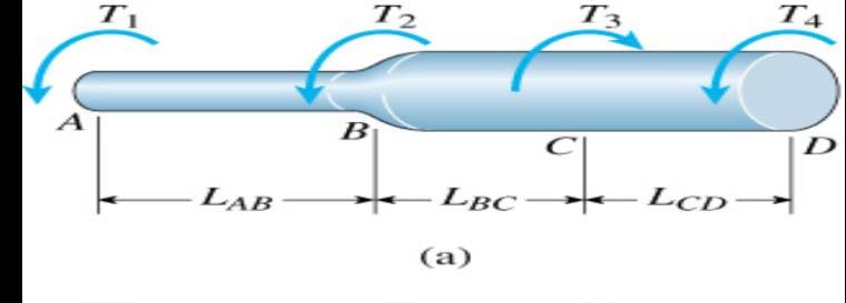
30 Example 3-8 A solid steel shaft ABC of 50mm diameter (Fig 3-13a) is driven at A by a motor that transmits 50 kw to the shaft at 10 Hz. The gears at B and C drive machinery requiring power equal to 35 kw and 15 kw, respectively. Compute the maximum shear stress in the shaft and the angle of twist between the motor at A and the gear at C. (Use G = 80 GPa.)
31 2001 Brooks/Cole, a division of Thomson Learning, Inc. Thomson Learning is a trademark used herein under license.
32 Solution Torques acting on the shaft. : torque applied at end shaft : torque applied at B : torque applied at C
33 The internal torques in the two segments
34 Shear stresses and angles of twist. the total angle of twist

35 3.8 STATICALLY INDETERMINATE TORSION MEMBERS Fig Statistically indeterminate bar in torsion

36 1) equation of equilibrium 2) equation of compatibility 3) torque-displacement relation( ) When the torque is applied at the end of the bar (in fig. 3-32) : diameter of internal of the bar : diameter of outer of the bar 1) equation of equilibrium
37 2) equation of compatibility : angle of the twist of the solid bar : angle of the twist of the tube bar 3) torque-displacement relation( ) from ( )
38 from 1) and 3)

39 Example 3-9 The bar ACB shown in Fig. 3-33a is fixed at both ends and loaded by a torque at point C. Segments AC and CB of the bar have diameters and,, length and and polar moments of inertia and, respectively. The material of the bar is the same throughout both segments. Obtain formulas for (a) the reactive torques and at the ends, (b) the maximum shear stresses and in each segment of the bar, and (c) the angle of rotation at the cross section where the load iis applied.
40 Fig Example 3-9. Statically indeterminate bar in torsion.
 torque-displacement")
41 Solution 1) equation of equilibrium 2) equation of compatibility 3) torque-displacement relation
42 3) ---> 2) or
43 As a special case, if ( ) maximum shear stresses :
44 Angle of twist : B in special case if

45 3.9 STRAIN ENERGY IN TORSION AND PURE SHEAR Consider a prismatic bar AB in pure torsion under the acting of a torque. Fig Prismatic bar in pure torsion
46 Fig Torque-rotation diagram for a bar in pure torsion (linearly elastic material)
47 Since W = U From compare

48 Nonuniform Torsion Fig Bar in nonuniform torsion
49 : the strain energy of the segment : the number of segment

50 Strain-Energy Density in Pure Shear : Because the individual elements of a bar in torsion are stressed in pure shear, it is useful to obtain expressions for the strain energy associated with the shear stresses. In Fig shear force :

51 Fig Element in pure shear
 Strain-Energy Density :")
52 Total Strain Energy : (from : volume of element) Strain-Energy Density : from
53 Example 3-10 A solid circular bar AB of length L is fixed at one end and free at the other(fig. 3-37). Three different loading conditions are to be considered: (a) torque acting at the free end; (b) torque acting at the midpoint of the bar; and (c) torque and acting simultaneously. Fig Example Strain energy produced by two loads Brooks/Cole, a division of Thomson Learning, Inc. Thomson Learning is a trademark used herein under license.
54 For each case of loading, obtain a formula for the strain energy stored in the bar. Then evaluate the strain energy for the following data: = 100 N m, = 150 N m, L = 1.6 m, G = 80 GPa, and =. Fig Example Strain energy produced by two loads Brooks/Cole, a division of Thomson Learning, Inc. Thomson Learning is a trademark used herein under license.
 torque acting at the midpoint of the")
55 Solution (a) torque acting at the free end; (b) torque acting at the midpoint of the bar;

56 (c) torque and acting simultaneously. torque of CB : torque of AC : + The strain energy of a structure supporting more than one load cannot be obtained by adding the strain energies obtained for the individual loads acting separately
57 (d) Numerical results : (1J=1N m)
58 Example 3-11 A prismatic bar AB, fixed at one end free at the other, is loaded by a distributed torque of constant intensity t per unit distance along the axis of the bar(fig. 3-38) (a) Derive a formula for the strain energy of the bar. (b) Evaluate the strain energy of the shaft if the data are as follows:
59 2001 Brooks/Cole, a division of Thomson Learning, Inc. Thomson Learning is a trademark used herein under license. Fig Example Strain energy produced by a distributed torque.

60 Solution (a) Derive a formula for the strain energy of the bar. (from ) (b) Numerical results :
61 Example 3-12 A tapered bar AB of solid circular cross section is supported at the right-hand end and loaded by a torque T at the other end(fig. 3-39). The diameter of the bar varies linearly from at the left-hand end to at the righthand end. Determine the angle of rotation at end A of the bar by equating the strain energy to the work done by the load.
62 2001 Brooks/Cole, a division of Thomson Learning, Inc. Thomson Learning is a trademark used herein under license. Fig Example Tapered bar in torsion.

63 Solution U=W
64 Substituting
65 , Thus, the integration equals
66 in which strain energy :
67 From
[7] Torsion. [7.1] Torsion. [7.2] Statically Indeterminate Torsion. [7] Torsion Page 1 of 21
![[7] Torsion. [7.1] Torsion. [7.2] Statically Indeterminate Torsion. [7] Torsion Page 1 of 21](/thumbs/88/115835122.jpg "[7] Torsion. [7.1] Torsion. [7.2] Statically Indeterminate Torsion. [7] Torsion Page 1 of 21") [7] Torsion Page 1 of 21 [7] Torsion [7.1] Torsion [7.2] Statically Indeterminate Torsion [7] Torsion Page 2 of 21 [7.1] Torsion SHEAR STRAIN DUE TO TORSION 1) A shaft with a circular cross section is
[7] Torsion Page 1 of 21 [7] Torsion [7.1] Torsion [7.2] Statically Indeterminate Torsion [7] Torsion Page 2 of 21 [7.1] Torsion SHEAR STRAIN DUE TO TORSION 1) A shaft with a circular cross section is
CIVL222 STRENGTH OF MATERIALS. Chapter 6. Torsion
 CIVL222 STRENGTH OF MATERIALS Chapter 6 Torsion Definition Torque is a moment that tends to twist a member about its longitudinal axis. Slender members subjected to a twisting load are said to be in torsion.
Chapter 5 Torsion STRUCTURAL MECHANICS: CE203. Notes are based on Mechanics of Materials: by R. C. Hibbeler, 7th Edition, Pearson
 STRUCTURAL MECHANICS: CE203 Chapter 5 Torsion Notes are based on Mechanics of Materials: by R. C. Hibbeler, 7th Edition, Pearson Dr B. Achour & Dr Eng. K. El-kashif Civil Engineering Department, University
Structural Analysis I Chapter 4 - Torsion TORSION
 ORSION orsional stress results from the action of torsional or twisting moments acting about the longitudinal axis of a shaft. he effect of the application of a torsional moment, combined with appropriate
MECHANICS OF MATERIALS
 2009 The McGraw-Hill Companies, Inc. All rights reserved. Fifth SI Edition CHAPTER 3 MECHANICS OF MATERIALS Ferdinand P. Beer E. Russell Johnston, Jr. John T. DeWolf David F. Mazurek Torsion Lecture Notes:
Stress Analysis Lecture 3 ME 276 Spring Dr./ Ahmed Mohamed Nagib Elmekawy
 Stress Analysis Lecture 3 ME 276 Spring 2017-2018 Dr./ Ahmed Mohamed Nagib Elmekawy Axial Stress 2 Beam under the action of two tensile forces 3 Beam under the action of two tensile forces 4 Shear Stress
EMA 3702 Mechanics & Materials Science (Mechanics of Materials) Chapter 3 Torsion
 Chapter 3 Torsion") EMA 3702 Mechanics & Materials Science (Mechanics of Materials) Chapter 3 Torsion Introduction Stress and strain in components subjected to torque T Circular Cross-section shape Material Shaft design Non-circular
EMA 3702 Mechanics & Materials Science (Mechanics of Materials) Chapter 3 Torsion Introduction Stress and strain in components subjected to torque T Circular Cross-section shape Material Shaft design Non-circular
WORCESTER POLYTECHNIC INSTITUTE
 WORCESTER POLYTECHNIC INSTITUTE MECHANICAL ENGINEERING DEPARTMENT STRESS ANALYSIS ES-2502, C 2012 Lecture 17: 10 February 2012 General information Instructor: Cosme Furlong HL-151 (508) 831-5126 cfurlong@wpi.edu
MECE 3321: MECHANICS OF SOLIDS CHAPTER 5
 MECE 3321: MECHANICS OF SOLIDS CHAPTER 5 SAMANTHA RAMIREZ TORSION Torque A moment that tends to twist a member about its longitudinal axis 1 TORSIONAL DEFORMATION OF A CIRCULAR SHAFT Assumption If the
PDDC 1 st Semester Civil Engineering Department Assignments of Mechanics of Solids [ ] Introduction, Fundamentals of Statics
![PDDC 1 st Semester Civil Engineering Department Assignments of Mechanics of Solids [ ] Introduction, Fundamentals of Statics](/thumbs/92/109382806.jpg "PDDC 1 st Semester Civil Engineering Department Assignments of Mechanics of Solids [ ] Introduction, Fundamentals of Statics") Page1 PDDC 1 st Semester Civil Engineering Department Assignments of Mechanics of Solids [2910601] Introduction, Fundamentals of Statics 1. Differentiate between Scalar and Vector quantity. Write S.I.
Page1 PDDC 1 st Semester Civil Engineering Department Assignments of Mechanics of Solids [2910601] Introduction, Fundamentals of Statics 1. Differentiate between Scalar and Vector quantity. Write S.I.
The problem of transmitting a torque or rotary motion from one plane to another is frequently encountered in machine design.
 CHAPER ORSION ORSION orsion refers to the twisting of a structural member when it is loaded by moments/torques that produce rotation about the longitudinal axis of the member he problem of transmitting
Members Subjected to Torsional Loads
 Members Subjected to Torsional Loads Torsion of circular shafts Definition of Torsion: Consider a shaft rigidly clamped at one end and twisted at the other end by a torque T = F.d applied in a plane perpendicular
Chapter 5: Torsion. 1. Torsional Deformation of a Circular Shaft 2. The Torsion Formula 3. Power Transmission 4. Angle of Twist CHAPTER OBJECTIVES
 CHAPTER OBJECTIVES Chapter 5: Torsion Discuss effects of applying torsional loading to a long straight member (shaft or tube) Determine stress distribution within the member under torsional load Determine
(48) CHAPTER 3: TORSION
 CHAPTER 3: TORSION") (48) CHAPTER 3: TORSION Introduction: In this chapter structural members and machine parts that are in torsion will be considered. More specifically, you will analyze the stresses and strains in members
(48) CHAPTER 3: TORSION Introduction: In this chapter structural members and machine parts that are in torsion will be considered. More specifically, you will analyze the stresses and strains in members
The example of shafts; a) Rotating Machinery; Propeller shaft, Drive shaft b) Structural Systems; Landing gear strut, Flap drive mechanism
 Rotating Machinery; Propeller shaft, Drive shaft b) Structural Systems; Landing gear strut, Flap drive mechanism") TORSION OBJECTIVES: This chapter starts with torsion theory in the circular cross section followed by the behaviour of torsion member. The calculation of the stress stress and the angle of twist will be
TORSION OBJECTIVES: This chapter starts with torsion theory in the circular cross section followed by the behaviour of torsion member. The calculation of the stress stress and the angle of twist will be
Chapter Objectives. Copyright 2011 Pearson Education South Asia Pte Ltd
 Chapter Objectives To determine the torsional deformation of a perfectly elastic circular shaft. To determine the support reactions when these reactions cannot be determined solely from the moment equilibrium
QUESTION BANK SEMESTER: III SUBJECT NAME: MECHANICS OF SOLIDS
 QUESTION BANK SEMESTER: III SUBJECT NAME: MECHANICS OF SOLIDS UNIT 1- STRESS AND STRAIN PART A (2 Marks) 1. Define longitudinal strain and lateral strain. 2. State Hooke s law. 3. Define modular ratio,
Mechanical Design in Optical Engineering
 Torsion Torsion: Torsion refers to the twisting of a structural member that is loaded by couples (torque) that produce rotation about the member s longitudinal axis. In other words, the member is loaded
QUESTION BANK DEPARTMENT: CIVIL SEMESTER: III SUBJECT CODE: CE2201 SUBJECT NAME: MECHANICS OF SOLIDS UNIT 1- STRESS AND STRAIN PART A
 DEPARTMENT: CIVIL SUBJECT CODE: CE2201 QUESTION BANK SEMESTER: III SUBJECT NAME: MECHANICS OF SOLIDS UNIT 1- STRESS AND STRAIN PART A (2 Marks) 1. Define longitudinal strain and lateral strain. 2. State
Torsion of Shafts Learning objectives
 Torsion of Shafts Shafts are structural members with length significantly greater than the largest cross-sectional dimension used in transmitting torque from one plane to another. Learning objectives Understand
M. Vable Mechanics of Materials: Chapter 5. Torsion of Shafts
 Torsion of Shafts Shafts are structural members with length significantly greater than the largest cross-sectional dimension used in transmitting torque from one plane to another. Learning objectives Understand
Torsion Stresses in Tubes and Rods
 Torsion Stresses in Tubes and Rods This initial analysis is valid only for a restricted range of problem for which the assumptions are: Rod is initially straight. Rod twists without bending. Material is
UNIT-I Introduction & Plane Stress and Plane Strain Analysis
 SIDDHARTH INSTITUTE OF ENGINEERING & TECHNOLOGY:: PUTTUR (AUTONOMOUS) Siddharth Nagar, Narayanavanam Road 517583 QUESTION BANK (DESCRIPTIVE) Subject with Code : Advanced Solid Mechanics (18CE1002) Year
MECHANICS OF MATERIALS
 GE SI CHAPTER 3 MECHANICS OF MATERIALS Ferdinand P. Beer E. Russell Johnston, Jr. John T. DeWolf David F. Mazurek Torsion Lecture Notes: J. Walt Oler Texas Tech University Torsional Loads on Circular Shafts
2. Polar moment of inertia As stated above, the polar second moment of area, J is defined as. Sample copy
 GATE PATHSHALA - 91. Polar moment of inertia As stated above, the polar second moment of area, is defined as z π r dr 0 R r π R π D For a solid shaft π (6) QP 0 π d Solid shaft π d Hollow shaft, " ( do
High Tech High Top Hat Technicians. An Introduction to Solid Mechanics. Is that supposed to bend there?
 High Tech High Top Hat Technicians An Introduction to Solid Mechanics Or Is that supposed to bend there? Why don't we fall through the floor? The power of any Spring is in the same proportion with the
MAAE 2202 A. Come to the PASS workshop with your mock exam complete. During the workshop you can work with other students to review your work.
 It is most beneficial to you to write this mock final exam UNDER EXAM CONDITIONS. This means: Complete the exam in 3 hours. Work on your own. Keep your textbook closed. Attempt every question. After the
ME Final Exam. PROBLEM NO. 4 Part A (2 points max.) M (x) y. z (neutral axis) beam cross-sec+on. 20 kip ft. 0.2 ft. 10 ft. 0.1 ft.
 M (x) y. z (neutral axis) beam cross-sec+on. 20 kip ft. 0.2 ft. 10 ft. 0.1 ft.") ME 323 - Final Exam Name December 15, 2015 Instructor (circle) PROEM NO. 4 Part A (2 points max.) Krousgrill 11:30AM-12:20PM Ghosh 2:30-3:20PM Gonzalez 12:30-1:20PM Zhao 4:30-5:20PM M (x) y 20 kip ft 0.2
ME 323 - Final Exam Name December 15, 2015 Instructor (circle) PROEM NO. 4 Part A (2 points max.) Krousgrill 11:30AM-12:20PM Ghosh 2:30-3:20PM Gonzalez 12:30-1:20PM Zhao 4:30-5:20PM M (x) y 20 kip ft 0.2
Shear Forces And Bending Moments
 Shear Forces And Bending Moments 1 Introduction 2001 Brooks/Cole, a division of Thomson Learning, Inc. Thomson Learning is a trademark used herein under license. Fig. 4-1 Examples of beams subjected to
NAME: Given Formulae: Law of Cosines: Law of Sines:
 NME: Given Formulae: Law of Cosines: EXM 3 PST PROBLEMS (LESSONS 21 TO 28) 100 points Thursday, November 16, 2017, 7pm to 9:30, Room 200 You are allowed to use a calculator and drawing equipment, only.
D : SOLID MECHANICS. Q. 1 Q. 9 carry one mark each.
 GTE 2016 Q. 1 Q. 9 carry one mark each. D : SOLID MECHNICS Q.1 single degree of freedom vibrating system has mass of 5 kg, stiffness of 500 N/m and damping coefficient of 100 N-s/m. To make the system
Sub. Code:
 Important Instructions to examiners: ) The answers should be examined by key words and not as word-to-word as given in the model answer scheme. ) The model answer and the answer written by candidate may
2. Rigid bar ABC supports a weight of W = 50 kn. Bar ABC is pinned at A and supported at B by rod (1). What is the axial force in rod (1)?
. What is the axial force in rod (1)?") IDE 110 S08 Test 1 Name: 1. Determine the internal axial forces in segments (1), (2) and (3). (a) N 1 = kn (b) N 2 = kn (c) N 3 = kn 2. Rigid bar ABC supports a weight of W = 50 kn. Bar ABC is pinned at
IDE 110 S08 Test 1 Name: 1. Determine the internal axial forces in segments (1), (2) and (3). (a) N 1 = kn (b) N 2 = kn (c) N 3 = kn 2. Rigid bar ABC supports a weight of W = 50 kn. Bar ABC is pinned at
Mechanics of Materials II. Chapter III. A review of the fundamental formulation of stress, strain, and deflection
 Mechanics of Materials II Chapter III A review of the fundamental formulation of stress, strain, and deflection Outline Introduction Assumtions and limitations Axial loading Torsion of circular shafts
MARKS DISTRIBUTION AS PER CHAPTER (QUESTION ASKED IN GTU EXAM) Name Of Chapter. Applications of. Friction. Centroid & Moment.
 Name Of Chapter. Applications of. Friction. Centroid & Moment.") Introduction Fundamentals of statics Applications of fundamentals of statics Friction Centroid & Moment of inertia Simple Stresses & Strain Stresses in Beam Torsion Principle Stresses DEPARTMENT OF CIVIL
Introduction Fundamentals of statics Applications of fundamentals of statics Friction Centroid & Moment of inertia Simple Stresses & Strain Stresses in Beam Torsion Principle Stresses DEPARTMENT OF CIVIL
Stress Transformation Equations: u = +135 (Fig. a) s x = 80 MPa s y = 0 t xy = 45 MPa. we obtain, cos u + t xy sin 2u. s x = s x + s y.
 s x = 80 MPa s y = 0 t xy = 45 MPa. we obtain, cos u + t xy sin 2u. s x = s x + s y.") 014 Pearson Education, Inc., Upper Saddle River, NJ. All rights reserved. This material is protected under all copyright laws as they currently 9 7. Determine the normal stress and shear stress acting
014 Pearson Education, Inc., Upper Saddle River, NJ. All rights reserved. This material is protected under all copyright laws as they currently 9 7. Determine the normal stress and shear stress acting
Solid Mechanics Chapter 1: Tension, Compression and Shear
 Solid Mechanics Chapter 1: Tension, Compression and Shear Dr. Imran Latif Department of Civil and Environmental Engineering College of Engineering University of Nizwa (UoN) 1 Why do we study Mechanics
SN QUESTION YEAR MARK 1. State and prove the relationship between shearing stress and rate of change of bending moment at a section in a loaded beam.
 ALPHA COLLEGE OF ENGINEERING AND TECHNOLOGY DEPARTMENT OF MECHANICAL ENGINEERING MECHANICS OF SOLIDS (21000) ASSIGNMENT 1 SIMPLE STRESSES AND STRAINS SN QUESTION YEAR MARK 1 State and prove the relationship
PURE BENDING. If a simply supported beam carries two point loads of 10 kn as shown in the following figure, pure bending occurs at segment BC.
 BENDING STRESS The effect of a bending moment applied to a cross-section of a beam is to induce a state of stress across that section. These stresses are known as bending stresses and they act normally
R13. II B. Tech I Semester Regular Examinations, Jan MECHANICS OF SOLIDS (Com. to ME, AME, AE, MTE) PART-A
 PART-A") SET - 1 II B. Tech I Semester Regular Examinations, Jan - 2015 MECHANICS OF SOLIDS (Com. to ME, AME, AE, MTE) Time: 3 hours Max. Marks: 70 Note: 1. Question Paper consists of two parts (Part-A and Part-B)
SET - 1 II B. Tech I Semester Regular Examinations, Jan - 2015 MECHANICS OF SOLIDS (Com. to ME, AME, AE, MTE) Time: 3 hours Max. Marks: 70 Note: 1. Question Paper consists of two parts (Part-A and Part-B)
Solution: The strain in the bar is: ANS: E =6.37 GPa Poison s ration for the material is:
 Problem 10.4 A prismatic bar with length L 6m and a circular cross section with diameter D 0.0 m is subjected to 0-kN compressive forces at its ends. The length and diameter of the deformed bar are measured
Aluminum shell. Brass core. 40 in
 PROBLEM #1 (22 points) A solid brass core is connected to a hollow rod made of aluminum. Both are attached at each end to a rigid plate as shown in Fig. 1. The moduli of aluminum and brass are EA=11,000
BE Semester- I ( ) Question Bank (MECHANICS OF SOLIDS)
 Question Bank (MECHANICS OF SOLIDS)") BE Semester- I ( ) Question Bank (MECHANICS OF SOLIDS) All questions carry equal marks(10 marks) Q.1 (a) Write the SI units of following quantities and also mention whether it is scalar or vector: (i)
BE Semester- I ( ) Question Bank (MECHANICS OF SOLIDS) All questions carry equal marks(10 marks) Q.1 (a) Write the SI units of following quantities and also mention whether it is scalar or vector: (i)
INTRODUCTION TO STRAIN
 SIMPLE STRAIN INTRODUCTION TO STRAIN In general terms, Strain is a geometric quantity that measures the deformation of a body. There are two types of strain: normal strain: characterizes dimensional changes,
KINGS COLLEGE OF ENGINEERING DEPARTMENT OF MECHANICAL ENGINEERING QUESTION BANK. Subject code/name: ME2254/STRENGTH OF MATERIALS Year/Sem:II / IV
 KINGS COLLEGE OF ENGINEERING DEPARTMENT OF MECHANICAL ENGINEERING QUESTION BANK Subject code/name: ME2254/STRENGTH OF MATERIALS Year/Sem:II / IV UNIT I STRESS, STRAIN DEFORMATION OF SOLIDS PART A (2 MARKS)
CHAPTER 4: BENDING OF BEAMS
 (74) CHAPTER 4: BENDING OF BEAMS This chapter will be devoted to the analysis of prismatic members subjected to equal and opposite couples M and M' acting in the same longitudinal plane. Such members are
4. SHAFTS. A shaft is an element used to transmit power and torque, and it can support
 4. SHAFTS A shaft is an element used to transmit power and torque, and it can support reverse bending (fatigue). Most shafts have circular cross sections, either solid or tubular. The difference between
Mechanics of Materials
 Mechanics of Materials 2. Introduction Dr. Rami Zakaria References: 1. Engineering Mechanics: Statics, R.C. Hibbeler, 12 th ed, Pearson 2. Mechanics of Materials: R.C. Hibbeler, 9 th ed, Pearson 3. Mechanics
Chapter 3. Load and Stress Analysis. Lecture Slides
 Lecture Slides Chapter 3 Load and Stress Analysis 2015 by McGraw Hill Education. This is proprietary material solely for authorized instructor use. Not authorized for sale or distribution in any manner.
Members Subjected to Combined Loads
 Members Subjected to Combined Loads Combined Bending & Twisting : In some applications the shaft are simultaneously subjected to bending moment M and Torque T.The Bending moment comes on the shaft due
Experiment Two (2) Torsional testing of Circular Shafts
 Torsional testing of Circular Shafts") Experiment Two (2) Torsional testing of Circular Shafts Introduction: Torsion occurs when any shaft is subjected to a torque. This is true whether the shaft is rotating (such as drive shafts on engines,
Experiment Two (2) Torsional testing of Circular Shafts Introduction: Torsion occurs when any shaft is subjected to a torque. This is true whether the shaft is rotating (such as drive shafts on engines,
MECHANICS OF SOLIDS Credit Hours: 6
 MECHANICS OF SOLIDS Credit Hours: 6 Teaching Scheme Theory Tutorials Practical Total Credit Hours/week 4 0 6 6 Marks 00 0 50 50 6 A. Objective of the Course: Objectives of introducing this subject at second
[5] Stress and Strain
![[5] Stress and Strain](/thumbs/95/123344550.jpg "[5] Stress and Strain") [5] Stress and Strain Page 1 of 34 [5] Stress and Strain [5.1] Internal Stress of Solids [5.2] Design of Simple Connections (will not be covered in class) [5.3] Deformation and Strain [5.4] Hooke s Law
[5] Stress and Strain Page 1 of 34 [5] Stress and Strain [5.1] Internal Stress of Solids [5.2] Design of Simple Connections (will not be covered in class) [5.3] Deformation and Strain [5.4] Hooke s Law
Experiment: Torsion Test Expected Duration: 1.25 Hours
 Course: Higher Diploma in Civil Engineering Unit: Structural Analysis I Experiment: Expected Duration: 1.25 Hours Objective: 1. To determine the shear modulus of the metal specimens. 2. To determine the
PES Institute of Technology
 PES Institute of Technology Bangalore south campus, Bangalore-5460100 Department of Mechanical Engineering Faculty name : Madhu M Date: 29/06/2012 SEM : 3 rd A SEC Subject : MECHANICS OF MATERIALS Subject
Lab Exercise #3: Torsion
 Lab Exercise #3: Pre-lab assignment: Yes No Goals: 1. To evaluate the equations of angular displacement, shear stress, and shear strain for a shaft undergoing torsional stress. Principles: testing of round
Tuesday, February 11, Chapter 3. Load and Stress Analysis. Dr. Mohammad Suliman Abuhaiba, PE
 1 Chapter 3 Load and Stress Analysis 2 Chapter Outline Equilibrium & Free-Body Diagrams Shear Force and Bending Moments in Beams Singularity Functions Stress Cartesian Stress Components Mohr s Circle for
Constitutive Equations (Linear Elasticity)
") Constitutive quations (Linear lasticity) quations that characterize the physical properties of the material of a system are called constitutive equations. It is possible to find the applied stresses knowing
Constitutive quations (Linear lasticity) quations that characterize the physical properties of the material of a system are called constitutive equations. It is possible to find the applied stresses knowing
By Dr. Mohammed Ramidh
 Engineering Materials Design Lecture.6 the design of beams By Dr. Mohammed Ramidh 6.1 INTRODUCTION Finding the shear forces and bending moments is an essential step in the design of any beam. we usually
PERIYAR CENTENARY POLYTECHNIC COLLEGE PERIYAR NAGAR - VALLAM THANJAVUR. DEPARTMENT OF MECHANICAL ENGINEERING QUESTION BANK
 PERIYAR CENTENARY POLYTECHNIC COLLEGE PERIYAR NAGAR - VALLAM - 613 403 - THANJAVUR. DEPARTMENT OF MECHANICAL ENGINEERING QUESTION BANK Sub : Strength of Materials Year / Sem: II / III Sub Code : MEB 310
BME 207 Introduction to Biomechanics Spring 2017
 April 7, 2017 UNIVERSITY OF RHODE ISAND Department of Electrical, Computer and Biomedical Engineering BE 207 Introduction to Biomechanics Spring 2017 Homework 7 Problem 14.3 in the textbook. In addition
Problem d d d B C E D. 0.8d. Additional lecturebook examples 29 ME 323
 Problem 9.1 Two beam segments, AC and CD, are connected together at C by a frictionless pin. Segment CD is cantilevered from a rigid support at D, and segment AC has a roller support at A. a) Determine
Strength of Materials Prof S. K. Bhattacharya Department of Civil Engineering Indian Institute of Technology, Kharagpur Lecture - 18 Torsion - I
 Strength of Materials Prof S. K. Bhattacharya Department of Civil Engineering Indian Institute of Technology, Kharagpur Lecture - 18 Torsion - I Welcome to the first lesson of Module 4 which is on Torsion
MECHANICS OF SOLIDS TORSION - TUTORIAL 1. You should judge your progress by completing the self assessment exercises.
 MECHANICS OF SOIS TORSION - TUTORIA 1 You should judge your progress by completing the self assessment exercises. On completion of this tutorial you should be able to do the following. erive the torsion
Drive Shaft Failure of Z-Drive Propulsion System. Suzanne Higgins
 Drive Shaft Failure of Z-Drive Propulsion System Suzanne Higgins Background Bunkering vessel MV Southern Valour Commissioned in 2008 in Singapore Operating in Cape Town harbour since August 2008 Z-Drive
Downloaded from Downloaded from / 1
 PURWANCHAL UNIVERSITY III SEMESTER FINAL EXAMINATION-2002 LEVEL : B. E. (Civil) SUBJECT: BEG256CI, Strength of Material Full Marks: 80 TIME: 03:00 hrs Pass marks: 32 Candidates are required to give their
Semester: BE 3 rd Subject :Mechanics of Solids ( ) Year: Faculty: Mr. Rohan S. Kariya. Tutorial 1
 Year: Faculty: Mr. Rohan S. Kariya. Tutorial 1") Semester: BE 3 rd Subject :Mechanics of Solids (2130003) Year: 2018-19 Faculty: Mr. Rohan S. Kariya Class: MA Tutorial 1 1 Define force and explain different type of force system with figures. 2 Explain
Semester: BE 3 rd Subject :Mechanics of Solids (2130003) Year: 2018-19 Faculty: Mr. Rohan S. Kariya Class: MA Tutorial 1 1 Define force and explain different type of force system with figures. 2 Explain
SSC-JE MAINS ONLINE TEST SERIES / CIVIL ENGINEERING SOM + TOS
 SSC-JE MAINS ONLINE TEST SERIES / CIVIL ENGINEERING SOM + TOS Time Allowed:2 Hours Maximum Marks: 300 Attention: 1. Paper consists of Part A (Civil & Structural) Part B (Electrical) and Part C (Mechanical)
The science of elasticity
 The science of elasticity In 1676 Hooke realized that 1.Every kind of solid changes shape when a mechanical force acts on it. 2.It is this change of shape which enables the solid to supply the reaction
EMA 3702 Mechanics & Materials Science (Mechanics of Materials) Chapter 2 Stress & Strain - Axial Loading
 Chapter 2 Stress & Strain - Axial Loading") MA 3702 Mechanics & Materials Science (Mechanics of Materials) Chapter 2 Stress & Strain - Axial Loading MA 3702 Mechanics & Materials Science Zhe Cheng (2018) 2 Stress & Strain - Axial Loading Statics
MA 3702 Mechanics & Materials Science (Mechanics of Materials) Chapter 2 Stress & Strain - Axial Loading MA 3702 Mechanics & Materials Science Zhe Cheng (2018) 2 Stress & Strain - Axial Loading Statics
EDEXCEL NATIONAL CERTIFICATE/DIPLOMA SCIENCE FOR TECHNICIANS OUTCOME 1 - STATIC AND DYNAMIC FORCES TUTORIAL 3 STRESS AND STRAIN
 EDEXCEL NATIONAL CERTIFICATE/DIPLOMA SCIENCE FOR TECHNICIANS OUTCOME 1 - STATIC AND DYNAMIC FORCES TUTORIAL 3 STRESS AND STRAIN 1 Static and dynamic forces Forces: definitions of: matter, mass, weight,
twenty one concrete construction: shear & deflection ARCHITECTURAL STRUCTURES: FORM, BEHAVIOR, AND DESIGN DR. ANNE NICHOLS SUMMER 2014 lecture
 ARCHITECTURAL STRUCTURES: FORM, BEHAVIOR, AND DESIGN DR. ANNE NICHOLS SUMMER 2014 lecture twenty one concrete construction: Copyright Kirk Martini shear & deflection Concrete Shear 1 Shear in Concrete
SRI CHANDRASEKHARENDRA SARASWATHI VISWA MAHAVIDHYALAYA
 SRI CHANDRASEKHARENDRA SARASWATHI VISWA MAHAVIDHYALAYA (Declared as Deemed-to-be University under Section 3 of the UGC Act, 1956, Vide notification No.F.9.9/92-U-3 dated 26 th May 1993 of the Govt. of
Reg. No. : Question Paper Code : B.Arch. DEGREE EXAMINATION, APRIL/MAY Second Semester AR 6201 MECHANICS OF STRUCTURES I
 WK 4 Reg. No. : Question Paper Code : 71387 B.Arch. DEGREE EXAMINATION, APRIL/MAY 2017. Second Semester AR 6201 MECHANICS OF STRUCTURES I (Regulations 2013) Time : Three hours Maximum : 100 marks Answer
Advanced Structural Analysis EGF Section Properties and Bending
 Advanced Structural Analysis EGF316 3. Section Properties and Bending 3.1 Loads in beams When we analyse beams, we need to consider various types of loads acting on them, for example, axial forces, shear
TORSION TEST. Figure 1 Schematic view of torsion test
 TORSION TEST 1. THE PURPOSE OF THE TEST The torsion test is performed for determining the properties of materials like shear modulus (G) and shear yield stress ( A ). 2. IDENTIFICATIONS: Shear modulus:
Torsion of shafts with circular symmetry
 orsion of shafts with circular symmetry Introduction Consider a uniform bar which is subject to a torque, eg through the action of two forces F separated by distance d, hence Fd orsion is the resultant
Torsion. Torsion is a moment that twists/deforms a member about its longitudinal axis
 Mehanis of Solids I Torsion Torsional loads on Cirular Shafts Torsion is a moment that twists/deforms a member about its longitudinal axis 1 Shearing Stresses due to Torque o Net of the internal shearing
Chapter 4 Deflection and Stiffness
 Chapter 4 Deflection and Stiffness Asst. Prof. Dr. Supakit Rooppakhun Chapter Outline Deflection and Stiffness 4-1 Spring Rates 4-2 Tension, Compression, and Torsion 4-3 Deflection Due to Bending 4-4 Beam
Chapter 1 General Introduction Instructor: Dr. Mürüde Çelikağ Office : CE Building Room CE230 and GE241
 CIVL222 STRENGTH OF MATERIALS Chapter 1 General Introduction Instructor: Dr. Mürüde Çelikağ Office : CE Building Room CE230 and GE241 E-mail : murude.celikag@emu.edu.tr 1. INTRODUCTION There are three
Mechanical Engineering Ph.D. Preliminary Qualifying Examination Solid Mechanics February 25, 2002
 student personal identification (ID) number on each sheet. Do not write your name on any sheet. #1. A homogeneous, isotropic, linear elastic bar has rectangular cross sectional area A, modulus of elasticity
Structural Metals Lab 1.2. Torsion Testing of Structural Metals. Standards ASTM E143: Shear Modulus at Room Temperature
 Torsion Testing of Structural Metals Standards ASTM E143: Shear Modulus at Room Temperature Purpose To determine the shear modulus of structural metals Equipment Tinius-Olsen Lo-Torq Torsion Machine (figure
VYSOKÁ ŠKOLA BÁŇSKÁ TECHNICKÁ UNIVERZITA OSTRAVA
 VYSOKÁ ŠKOLA BÁŇSKÁ TECHNICKÁ UNIVERZITA OSTRAVA FAKULTA METALURGIE A MATERIÁLOVÉHO INŽENÝRSTVÍ APPLIED MECHANICS Study Support Leo Václavek Ostrava 2015 Title:Applied Mechanics Code: Author: doc. Ing.
CHAPER THREE ANALYSIS OF PLANE STRESS AND STRAIN
 CHAPER THREE ANALYSIS OF PLANE STRESS AND STRAIN Introduction This chapter is concerned with finding normal and shear stresses acting on inclined sections cut through a member, because these stresses may
CE6306 STRENGTH OF MATERIALS TWO MARK QUESTIONS WITH ANSWERS ACADEMIC YEAR
 CE6306 STRENGTH OF MATERIALS TWO MARK QUESTIONS WITH ANSWERS ACADEMIC YEAR 2014-2015 UNIT - 1 STRESS, STRAIN AND DEFORMATION OF SOLIDS PART- A 1. Define tensile stress and tensile strain. The stress induced
STANDARD SAMPLE. Reduced section " Diameter. Diameter. 2" Gauge length. Radius
 MATERIAL PROPERTIES TENSILE MEASUREMENT F l l 0 A 0 F STANDARD SAMPLE Reduced section 2 " 1 4 0.505" Diameter 3 4 " Diameter 2" Gauge length 3 8 " Radius TYPICAL APPARATUS Load cell Extensometer Specimen
MECE 3321: Mechanics of Solids Chapter 6
 MECE 3321: Mechanics of Solids Chapter 6 Samantha Ramirez Beams Beams are long straight members that carry loads perpendicular to their longitudinal axis Beams are classified by the way they are supported
MECHANICS OF MATERIALS Design of a Transmission Shaft
 Design of a Transmission Shaft If power is transferred to and from the shaft by gears or sprocket wheels, the shaft is subjected to transverse loading as well as shear loading. Normal stresses due to transverse
AERO 214. Lab II. Measurement of elastic moduli using bending of beams and torsion of bars
 AERO 214 Lab II. Measurement of elastic moduli using bending of beams and torsion of bars BENDING EXPERIMENT Introduction Flexural properties of materials are of interest to engineers in many different
MECHANICS LAB AM 317 EXP 4 TORSION OF CIRCULAR RODS
 MECHANICS LAB AM 317 EXP 4 TORSION OF CIRCULAR RODS I. OBJECTIVES I.1 To become familiar with torsion tests of rods with solid circular cross sections. I.2 To observe the relation between shear stress
Strength of Materials Prof. S.K.Bhattacharya Dept. of Civil Engineering, I.I.T., Kharagpur Lecture No.26 Stresses in Beams-I
 Strength of Materials Prof. S.K.Bhattacharya Dept. of Civil Engineering, I.I.T., Kharagpur Lecture No.26 Stresses in Beams-I Welcome to the first lesson of the 6th module which is on Stresses in Beams
Mechanical Design. Design of Shaft
 Mechanical Design Design of Shaft Outline Practical information Shaft design Definition of shaft? It is a rotating member, in general, has a circular cross-section and is used to transmit power. The shaft
MECHANICS OF MATERIALS
 CHATR Stress MCHANICS OF MATRIALS and Strain Axial Loading Stress & Strain: Axial Loading Suitability of a structure or machine may depend on the deformations in the structure as well as the stresses induced
Module 2 Stresses in machine elements. Version 2 ME, IIT Kharagpur
 Module Stresses in machine elements Lesson Compound stresses in machine parts Instructional Objectives t the end of this lesson, the student should be able to understand Elements of force system at a beam
ME311 Machine Design
 ME311 Machine Design Lecture : Materials; Stress & Strain; Power Transmission W Dornfeld 13Sep018 airfield University School of Engineering Stress-Strain Curve for Ductile Material Ultimate Tensile racture
Stress-Strain Behavior
 Stress-Strain Behavior 6.3 A specimen of aluminum having a rectangular cross section 10 mm 1.7 mm (0.4 in. 0.5 in.) is pulled in tension with 35,500 N (8000 lb f ) force, producing only elastic deformation.
COURSE TITLE : APPLIED MECHANICS & STRENGTH OF MATERIALS COURSE CODE : 4017 COURSE CATEGORY : A PERIODS/WEEK : 6 PERIODS/ SEMESTER : 108 CREDITS : 5
 COURSE TITLE : APPLIED MECHANICS & STRENGTH OF MATERIALS COURSE CODE : 4017 COURSE CATEGORY : A PERIODS/WEEK : 6 PERIODS/ SEMESTER : 108 CREDITS : 5 TIME SCHEDULE MODULE TOPICS PERIODS 1 Simple stresses
Solution: T, A1, A2, A3, L1, L2, L3, E1, E2, E3, P are known Five equations in five unknowns, F1, F2, F3, ua and va
 ME 323 Examination # 1 February 18, 2016 Name (Print) (Last) (First) Instructor PROBLEM #1 (20 points) A structure is constructed from members 1, 2 and 3, with these members made up of the same material
18.Define the term modulus of resilience. May/June Define Principal Stress. 20. Define Hydrostatic Pressure.
 CE6306 STREGNTH OF MATERIALS Question Bank Unit-I STRESS, STRAIN, DEFORMATION OF SOLIDS PART-A 1. Define Poison s Ratio May/June 2009 2. What is thermal stress? May/June 2009 3. Estimate the load carried
6.4 A cylindrical specimen of a titanium alloy having an elastic modulus of 107 GPa ( psi) and
 and") 6.4 A cylindrical specimen of a titanium alloy having an elastic modulus of 107 GPa (15.5 10 6 psi) and an original diameter of 3.8 mm (0.15 in.) will experience only elastic deformation when a tensile
6.4 A cylindrical specimen of a titanium alloy having an elastic modulus of 107 GPa (15.5 10 6 psi) and an original diameter of 3.8 mm (0.15 in.) will experience only elastic deformation when a tensile