Solid Mechanics Chapter 1: Tension, Compression and Shear
|
|
|
- Aubrey Craig
- 5 years ago
- Views:
Transcription
1 Solid Mechanics Chapter 1: Tension, Compression and Shear Dr. Imran Latif Department of Civil and Environmental Engineering College of Engineering University of Nizwa (UoN) 1


2 Why do we study Mechanics of Solids? 2 Anyone concerned with the strength and physical performance of natural/man made structures should study Mechanics of Solids
")
3 Introduction to Mechanics of Solids 3 Definition: Mechanics of solids is a branch of applied mechanics that deals with the behaviour of solid bodies subjected to various types of loading Compression Tension Bending Torsion Shearing (streteched) (twisted)
4 Introduction to Mechanics of Solids 4 Fundamental concepts stress and strain deformation and displacement elasticity and inelasticity load carrying capacity Design and analysis of mechanical and structural systems
5 Introduction to Mechanics of Solids 5 Examination of stresses and strains inside real bodies of finite dimensions that deform under loads In order to determine stresses and strains we use: Physical properties of materials Theoretical laws and concepts

6 Problem solving 6 Draw the free body diagram Check your diagram Calculate the unknowns Check your working Compute the problem Check your working Write the solution Check your working

7 Free Body Diagram 7 Free Body Diagram The unknowns: R A, R B, R C

8 Free Body Diagram 8 Free Body Diagram The unknowns: A x, A y, CB
 and compression ( ) Type of loading for landing gear strut and for tow bar?")
9 Normal stress and strain 9 Most fundamental concepts in Mechanics of Materials are stress and strain Prismatic bar: Straight structural member with the same cross section throughout its length Axial force: Load directed along the axis of the member Axial force can be tensile or compressive Axial loads: Tension (+) and compression ( ) Type of loading for landing gear strut and for tow bar? Structural members subjected to axial loads

10 Normal stress and strain 10 A truss bridge is a type of beam bridge with a skeletal structure. The forces of tension, or pulling, are represented by red lines and the forces of compression, or squeezing, are represented by green lines.
11 Normal stress 11 Continuously distributed stresses acting over the entire cross section. Axial force P is the resultant of those stresses FBD of a segment of the bar Segment of the bar before loading Stress (σ) has units of force per unit area If stresses acting on cross section are uniformly distributed then: Segment of bar after loading Normal stresses in the bar Units of stress in USCS: pounds per square inch (psi) or kilopounds per square inch (ksi) SI units: newtons per square meter (N/m 2 ) which is equal to Pa
12 Limitations 12 The loads P are transmitted to the bar by pins that pass through the holes High localized stresses are produced around the holes!! Stress concentrations Steel eyebar subjected to tensile loads P
13 Normal strain A prismatic bar will change in length when under a uniaxial tensile force, and obviously it will become longer 13 Definition of elongation per unit length or strain (ε) FBD of a segment of the bar Segment of the bar before loading If bar is in tension, strain is tensile and if in compression the strain is compressive Strain is a dimensionless quantity (i.e. no units) Segment of bar after loading Normal stresses in the bar


14 Line of action of the axial forces for a uniform stress distribution 14 It can be demonstrated that in order to have uniform tension or compression in a prismatic bar, the axial force must act through the centroid of the crosssectional area.
 Compressive stress in the post.")
15 Example 15 A short post constructed from a hollow circular tube of aluminum supports a compressive load of 26 kips (26000 lb). The inner and outer diameters of the tube are d 1 = 4 in. and d 2 = 4.5 in. respectively, and its length is 16 in. The shortening of the post due to the load is measured as in. Determine: (a) Compressive stress in the post. (b) Compressive strain in the post.
16 16
 If the measured strain is 550 x 10-6 bar?")
17 Problem 17 Problem A circular aluminum tube of length L = 400 mm is loaded in compression by forces P (see figure). The outside and inside diameters are 60 mm and 50 mm, respectively. A strain gage is placed on the outside of the bar to measure normal strains in the longitudinal direction. (a) If the measured strain is 550 x 10-6 bar?, what is the shortening of the (b) If the compressive stress in the bar is intended to be 40 MPa, what should be the load P?
18 18 Problem Two steel wires, AB and BC, support a lamp weighing 18 lb (see figure). Wire AB is at an angle α = 34 to the horizontal and wire BC is at an angle β = 48. Both wires have diameter 30 mils. (Wire diameters are often expressed in mils; one mil equals in.) Determine the tensile stresses AB and BC in the two wires.
19 Mechanical properties of materials 19 In order to understand the mechanical behaviour of materials we need to perform experimental testing in the lab A tensile test machine is a typical equipment of a mechanical testing lab ASTM (American Society for Testing and Materials)
20 Stress ( ) strain ( ) diagrams 20
21 diagrams 21 Nominal stress and strain (in the calculations we use the initial cross sectional area A) True stress (in the calculations we use the cross sectional area A when failure occurs) True strain if we use a strain gauge Stress strain diagrams contain important information about mechanical properties and behaviour Stress strain diagram for a typical structural steel in tension (not to scale)
22 diagrams 22 OA: Initial region which is linear and proportional (Slope of OA is called modulus of elasticity) BC: Considerable elongation occurs with no noticeable increase in stress (yielding) CD: Strain hardening changes in crystalline structure (increased resistance to further deformation) DE: Further stretching leads to reduction in the applied load and fracture OABCE : True stress strain curve


23 Tensile coupon test specimens showing elongation immediately prior to failure (G.J. Davies) 23
24 diagrams 24 The strains from zero to point A are so small as compared to the strains from point A to E and can not be seen (it is a vertical line ) Metals, such as structural steel, that undergo permanent large strains before failure are ductile Ductile materials absorb large amounts of strain energy Ductile materials: aluminium, copper, magnesium, lead, molybdenum, nickel, brass, nylon, teflon Stress strain diagram for a typical structural steel in tension (drawn to scale)
25 Aluminum alloys 25 Although ductile, aluminium alloys typically do not have a clearly definable yield point However, they have an initial linear region with a recognizable proportional limit Structural alloys have proportional limits in the range of MPa and ultimate stresses in the range of MPa Typical stress strain diagram for an aluminum alloy.
26 Offset method 26 When the yield point is not obvious, like in the previous case, and undergoes large strains, an arbitrary yield stress can be determined by the offset method (e.g or 0.2%) The intersection of the offset line and the stress strain curve (point A) defines the yield stress
27 Brittle materials 27 Brittle materials fail at relatively low strains and little elongation after the proportional limit Brittle materials: concrete, marble, glass, ceramics and metallic alloys The reduction in the crosssectional area until fracture (point B) is insignificant and the fracture stress (point B) is the same as the ultimate stress Typical stress strain diagram for a brittle material showing the proportional limit (point A) and fracture stress (point B)

28 28 Problem Three different materials, designated A, B,and C, are tested in tension using test specimens having diameters of in. and gage lengths of 2.0 in. (see figure). At failure, the distances between the gage marks are found to be 2.13, 2.48, and 2.78 in., respectively. Also, at the failure cross sections the diameters are found to be0.484, 0.398, and in., respectively. Determine the percent elongation and percent reduction in area of each specimen, and then, using your own judgment, classify each material as brittle or ductile.
, and yield stress at 0.2% offset.")
29 29 Problem A specimen of a methacrylate plastic is tested in tension at room temperature (see figure), producing the stress-strain data listed in the accompanying table. Plot the stress-strain curve and determine the proportional limit, modulus of elasticity (i.e., the slope of the initial part of the stress-strain curve), and yield stress at 0.2% offset. Is the material ductile or brittle?


30 Solution to problem 30 Modulus of elasticity: 2.35 GPa Proportional limit: 47 MPa Yield stress: 52.5 MPa Material is brittle, because the strain after the proportional limit is exceeded is relatively small.
31 Elasticity 31 What happens when the load is removed (i.e. the material is unloaded)? Tensile load is applied from O to A (Fig 1) and when load is removed the material follows the same curve back. This property is called elasticity If we load the same material from O to B (Fig 2) and then unloading occurs, the material follows the line BC. Line OC represents the residual or permanent strain. Line CD represents the elastic recovery of the material. During unloading the material is partially elastic Fig. 1. Elastic behavior Fig. 2. Plastic behavior
32 Plasticity 32 Plasticity is the characteristic of a material which undergoes inelastic strains beyond the strain at the elastic limit When large deformations occur in a ductile material loaded in the plastic region, the material is undergoing plastic flow
33 Reloading of a material 33 If the material is in the elastic range, it can be loaded, unloaded and loaded again without significantly changing the behaviour When loaded in the plastic range, the internal structure of the material is altered and the properties change If the material is reloaded (fig 1 19), CB is a linearly elastic region with the same slope as the slope of the tangent to the original loading curve at origin O By stretching steel or aluminium into the plastic range, the properties of the material are changed
34 Creep 34 When loaded for periods of time, some materials develop additional strains and are said to creep Even though the load P remains constant after time t0, the bar gradually lengthens Relaxation is a process at which, after time t 0, the stress in the wire gradually diminishes and eventually is reaching a constant value Creep is more important at high temperatures and has to be considered in the design of engines and furnaces
35 Hooke s law 35 Many structural materials such as metals, wood, plastics and ceramics behave both elastically and linearly when first loaded and their stressstrain curve begin with a straight line passing through origin (line OA) Linear elastic materials are useful for designing structures and machines when permanent deformations, due to yielding, must be avoided
 The above equation is a limited version of Hooke s Law relating only the longitudinal stresses and strains that are developed during the uniaxial loading of a")
36 Hooke s law 36 The linear relationship between stress and strain for a bar in simple tension or compression is expressed by: σ is axial stress σ = E ε ε is axial strain E is modulus of elasticity Hooke s law Robert Hooke ( ) The above equation is a limited version of Hooke s Law relating only the longitudinal stresses and strains that are developed during the uniaxial loading of a prismatic bar Robert Hooke was an English inventor, microscopist, physicist, surveyor, astronomer, biologist and artist, who played an important role in the scientific revolution, through both theoretical and experimental work.
 Thomas Young was an English polymath, contributing to the scientific understanding of vision, light, solid mechanics, energy, physiology, and Egyptology.")
37 Modulus of Elasticity 37 E is called modulus of elasticity or Young s modulus and is a constant It is the slope of the stress strain curve in the linearly elastic region Units of E are the same as the units of stress (i.e. psi or Pa) Thomas Young was an English polymath, contributing to the scientific understanding of vision, light, solid mechanics, energy, physiology, and Egyptology.
38 Poisson s ratio 38 When a prismatic bar is loaded in tension the axial elongation is accompanied by lateral contraction longitudinal extension lateral contraction The lateral strain ε at any point in a bar is proportional to the axial strain ε at the same point if the material is linearly elastic The ratio of the above two strains is known as Poisson s ratio (ν) ν = (lateral strain / axial strain = (ε / ε )

39 Poisson s ratio The minus sign in the equation is because the lateral strain is negative (width of the bar decreases) and the axial tensile strain is positive. Therefore, the Poisson s ratio will have a positive value. When using the Poisson s ratio equation we need to know that it applies only to a prismatic bar in uni axial stress 39 Simeon Denis Poisson ( ) Poisson s value of concrete = Poisson s value of rubber = 0.5 Siméon Denis Poisson was a French mathematician, geometer, and physicist.

40 Limitations 40 Poisson s ratio is constant in the linearly elastic range Material must be homogeneous (same composition at every point) Materials having the same properties in all directions are called isotropic If the properties differ in various directions the materials called anisotropic
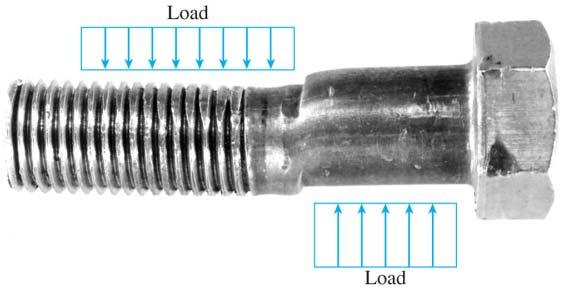
41 Shear stress and shear strain 41 Shear stress acts tangential to the surface of the material and not perpendicular perpendicular tangential Consider the bolted connection of Figure where A is a flat bar, C a clevis and B a bolt When load P is applied, the bar and clevis will press against the bolt and bearing stresses will be developed The bar and clevis tend to shear the bolt
 and draw")

 Based on the assumption of")

42 Shear stress and shear strain 42 If we have a closer look from the side view (fig b) and draw a FBD (fig c) Bearing stresses exerted by the clevis against the bolt appear on the left hand side (1 and 3) Stresses from the bar are on the right hand side (2) Based on the assumption of uniform stress distribution we can calculate an average bearing stress σ b total bearing force bearing area
43 Shear stress and shear strain 43 The bearing area A b is defined as the projected area of the curved bearing surface. For example (for stresses labeled 1) the projected area on which the stresses act is a rectangle with height equal to the thickness of the clevis and width equal to the diameter of the bolt The bearing force F b (for stresses labeled 1) is equal to P/2 The same area and force apply for stresses labeled 3 For bearing stresses labeled 2 the bearing area is a rectangle with height equal to the thickness of the flat bar and width equal to the diameter of the bolt. The force is equal to P
 of the portion mnqp of the bolt we see that the shear forces V act over the cut surfaces of the bolt. There are two planes of shear (plane mn and plane pq).")
44 Shear stress and shear strain 44 The FBD (fig. c) shows that there is a tendency to shear the bolt along the cross sections mn and pq From the FBD (fig. d) of the portion mnqp of the bolt we see that the shear forces V act over the cut surfaces of the bolt. There are two planes of shear (plane mn and plane pq). Therefore, the bolt is in double shear The shear stresses acting on the cross section mn are shown (fig. e) Shear stresses are denoted by τ
 we see the shear force V (equal to load P).")
45 Single shear 45 The axial force P in the metal bar is transmitted to the flange of the steel column through a bolt A cross section of the column (fig b) shows more details Fig c shows the assumed distribution of the bearing stresses acting on the bolt Cutting through the bolt at section mn (fig d) we see the shear force V (equal to load P). V is the resultant of the shear stresses that act over the cross sectional area of the bolt

46 Single shear 46
47 Shear stress and strain 47 Discussing about bolted connections we disregard friction which is produced by tightening the bolts Average shear stress on the cross section of a bolt is obtained by dividing the total shear force V by the area A of the cross section on which it acts: Shear stresses have the same units as normal stresses The two previous examples (double and single shear) are examples of direct shear Direct shear arises in the design of bolts, pins, rivets, keys, welds and glued joints
48 48 Consider a small rectangular parallelepiped element Assume that a shear stress τ 1 is uniformly distributed over the right hand side area bc (τ 1bc ) For equilibrium in the y direction the τ 1bc must be balanced by an equal and of opposite direction shear force on the left hand side The forces τ 1bc acting on the right hand and left hand side faces form a couple having a moment about z axis equal to τ 1.abc (counterclockwise direction) Small element of material subjected to shear stresses

49 Equality of shear stresses on perpendicular planes 49 Similarly, in order to have equilibrium of the element, we have a shear force τ 2.ac and consequently a clockwise couple of moment τ 2.abc It is therefore evident that for moment equilibrium we have: τ 1 = τ 2 1. Shear stresses on opposite and parallel faces of an element are equal in magnitude and opposite in direction 2. Shear stresses on adjacent and perpendicular faces of an element are equal in magnitude and have directions such that both stresses point toward, or both point away from, the line of intersection of the faces

 is a measure of distortion of the element")
50 50 Shear stresses acting on an element of material (fig a) are accompanied by shear strains The lengths of the sides of the element do not change but, the shear stresses produce a change in the shape of the element Rectangular parallelepiped becomes oblique parallelepiped. Front and rear faces become rhomboids The angle γ (fig b) is a measure of distortion of the element and is called shear strain
51 Hooke s law in shear 51 We can plot shear stress strain diagrams Hooke s Law in shear shear stress τ = Gγ shear modulus of elasticity shear strain G has the same units as E (Young s modulus) G and E are also related by: G = E / (2(1+ν)) Poisson s ratio

 = Actual strength /")
52 Allowable stresses & allowable loads 52 The principal design interest is strength Strength is the capacity of the object to support or transmit loads The actual strength of a structure must exceed the required strength Factor of safety must be greater than 1 if failure is to be avoided Factors of safety from slightly above 1 to as much as 10 are used Factor of safety (n) = Actual strength / Required strength
53 Allowable stresses & allowable loads 53 Allowable stress = Yield strength / Factor of safety tension shear σ allow = σ Y / n 1 τ allow = τ Y / n 2 OR Allowable stress = Ultimate strength / Factor of safety tension shear σ allow = σ U / n 3 τ allow = τ U / n 4
 (Area) For bars in")

54 Allowable loads 54 Allowable load is also called permissible load or the safe load Allowable load = (Allowable stress) (Area) For bars in tension or compression: P allow = σ allow. A For pins in direct shear: P allow = τ allow. A Permissible load based upon bearing: P allow = σ b. A
NORMAL STRESS. The simplest form of stress is normal stress/direct stress, which is the stress perpendicular to the surface on which it acts.
 NORMAL STRESS The simplest form of stress is normal stress/direct stress, which is the stress perpendicular to the surface on which it acts. σ = force/area = P/A where σ = the normal stress P = the centric
[5] Stress and Strain
![[5] Stress and Strain](/thumbs/95/123344550.jpg "[5] Stress and Strain") [5] Stress and Strain Page 1 of 34 [5] Stress and Strain [5.1] Internal Stress of Solids [5.2] Design of Simple Connections (will not be covered in class) [5.3] Deformation and Strain [5.4] Hooke s Law
[5] Stress and Strain Page 1 of 34 [5] Stress and Strain [5.1] Internal Stress of Solids [5.2] Design of Simple Connections (will not be covered in class) [5.3] Deformation and Strain [5.4] Hooke s Law
MECE 3321 MECHANICS OF SOLIDS CHAPTER 3
 MECE 3321 MECHANICS OF SOLIDS CHAPTER 3 Samantha Ramirez TENSION AND COMPRESSION TESTS Tension and compression tests are used primarily to determine the relationship between σ avg and ε avg in any material.
Mechanical Properties of Materials
 Mechanical Properties of Materials Strains Material Model Stresses Learning objectives Understand the qualitative and quantitative description of mechanical properties of materials. Learn the logic of
ME 2570 MECHANICS OF MATERIALS
 ME 2570 MECHANICS OF MATERIALS Chapter III. Mechanical Properties of Materials 1 Tension and Compression Test The strength of a material depends on its ability to sustain a load without undue deformation
Samantha Ramirez, MSE. Stress. The intensity of the internal force acting on a specific plane (area) passing through a point. F 2
 passing through a point. F 2") Samantha Ramirez, MSE Stress The intensity of the internal force acting on a specific plane (area) passing through a point. Δ ΔA Δ z Δ 1 2 ΔA Δ x Δ y ΔA is an infinitesimal size area with a uniform force
Samantha Ramirez, MSE Stress The intensity of the internal force acting on a specific plane (area) passing through a point. Δ ΔA Δ z Δ 1 2 ΔA Δ x Δ y ΔA is an infinitesimal size area with a uniform force
MECHANICS OF MATERIALS. Prepared by Engr. John Paul Timola
 MECHANICS OF MATERIALS Prepared by Engr. John Paul Timola Mechanics of materials branch of mechanics that studies the internal effects of stress and strain in a solid body. stress is associated with the
Mechanics of Solids. Mechanics Of Solids. Suraj kr. Ray Department of Civil Engineering
 Mechanics Of Solids Suraj kr. Ray (surajjj2445@gmail.com) Department of Civil Engineering 1 Mechanics of Solids is a branch of applied mechanics that deals with the behaviour of solid bodies subjected
ME 243. Mechanics of Solids
 ME 243 Mechanics of Solids Lecture 2: Stress and Strain Ahmad Shahedi Shakil Lecturer, Dept. of Mechanical Engg, BUET E-mail: sshakil@me.buet.ac.bd, shakil6791@gmail.com Website: teacher.buet.ac.bd/sshakil
Stress-Strain Behavior
 Stress-Strain Behavior 6.3 A specimen of aluminum having a rectangular cross section 10 mm 1.7 mm (0.4 in. 0.5 in.) is pulled in tension with 35,500 N (8000 lb f ) force, producing only elastic deformation.
PDDC 1 st Semester Civil Engineering Department Assignments of Mechanics of Solids [ ] Introduction, Fundamentals of Statics
![PDDC 1 st Semester Civil Engineering Department Assignments of Mechanics of Solids [ ] Introduction, Fundamentals of Statics](/thumbs/92/109382806.jpg "PDDC 1 st Semester Civil Engineering Department Assignments of Mechanics of Solids [ ] Introduction, Fundamentals of Statics") Page1 PDDC 1 st Semester Civil Engineering Department Assignments of Mechanics of Solids [2910601] Introduction, Fundamentals of Statics 1. Differentiate between Scalar and Vector quantity. Write S.I.
Page1 PDDC 1 st Semester Civil Engineering Department Assignments of Mechanics of Solids [2910601] Introduction, Fundamentals of Statics 1. Differentiate between Scalar and Vector quantity. Write S.I.
Strength of Materials (15CV 32)
") Strength of Materials (15CV 32) Module 1 : Simple Stresses and Strains Dr. H. Ananthan, Professor, VVIET,MYSURU 8/21/2017 Introduction, Definition and concept and of stress and strain. Hooke s law, Stress-Strain
Strength of Materials (15CV 32) Module 1 : Simple Stresses and Strains Dr. H. Ananthan, Professor, VVIET,MYSURU 8/21/2017 Introduction, Definition and concept and of stress and strain. Hooke s law, Stress-Strain
Mechanics of Materials Primer
 Mechanics of Materials rimer Notation: A = area (net = with holes, bearing = in contact, etc...) b = total width of material at a horizontal section d = diameter of a hole D = symbol for diameter E = modulus
4.MECHANICAL PROPERTIES OF MATERIALS
 4.MECHANICAL PROPERTIES OF MATERIALS The diagram representing the relation between stress and strain in a given material is an important characteristic of the material. To obtain the stress-strain diagram
INTRODUCTION TO STRAIN
 SIMPLE STRAIN INTRODUCTION TO STRAIN In general terms, Strain is a geometric quantity that measures the deformation of a body. There are two types of strain: normal strain: characterizes dimensional changes,
Mechanics of Materials II. Chapter III. A review of the fundamental formulation of stress, strain, and deflection
 Mechanics of Materials II Chapter III A review of the fundamental formulation of stress, strain, and deflection Outline Introduction Assumtions and limitations Axial loading Torsion of circular shafts
Chapter 7. Highlights:
 Chapter 7 Highlights: 1. Understand the basic concepts of engineering stress and strain, yield strength, tensile strength, Young's(elastic) modulus, ductility, toughness, resilience, true stress and true
Structural Analysis I Chapter 4 - Torsion TORSION
 ORSION orsional stress results from the action of torsional or twisting moments acting about the longitudinal axis of a shaft. he effect of the application of a torsional moment, combined with appropriate
QUESTION BANK SEMESTER: III SUBJECT NAME: MECHANICS OF SOLIDS
 QUESTION BANK SEMESTER: III SUBJECT NAME: MECHANICS OF SOLIDS UNIT 1- STRESS AND STRAIN PART A (2 Marks) 1. Define longitudinal strain and lateral strain. 2. State Hooke s law. 3. Define modular ratio,
EMA 3702 Mechanics & Materials Science (Mechanics of Materials) Chapter 2 Stress & Strain - Axial Loading
 Chapter 2 Stress & Strain - Axial Loading") MA 3702 Mechanics & Materials Science (Mechanics of Materials) Chapter 2 Stress & Strain - Axial Loading MA 3702 Mechanics & Materials Science Zhe Cheng (2018) 2 Stress & Strain - Axial Loading Statics
MA 3702 Mechanics & Materials Science (Mechanics of Materials) Chapter 2 Stress & Strain - Axial Loading MA 3702 Mechanics & Materials Science Zhe Cheng (2018) 2 Stress & Strain - Axial Loading Statics
QUESTION BANK DEPARTMENT: CIVIL SEMESTER: III SUBJECT CODE: CE2201 SUBJECT NAME: MECHANICS OF SOLIDS UNIT 1- STRESS AND STRAIN PART A
 DEPARTMENT: CIVIL SUBJECT CODE: CE2201 QUESTION BANK SEMESTER: III SUBJECT NAME: MECHANICS OF SOLIDS UNIT 1- STRESS AND STRAIN PART A (2 Marks) 1. Define longitudinal strain and lateral strain. 2. State
The University of Melbourne Engineering Mechanics
 The University of Melbourne 436-291 Engineering Mechanics Tutorial Four Poisson s Ratio and Axial Loading Part A (Introductory) 1. (Problem 9-22 from Hibbeler - Statics and Mechanics of Materials) A short
The science of elasticity
 The science of elasticity In 1676 Hooke realized that 1.Every kind of solid changes shape when a mechanical force acts on it. 2.It is this change of shape which enables the solid to supply the reaction
Constitutive Equations (Linear Elasticity)
") Constitutive quations (Linear lasticity) quations that characterize the physical properties of the material of a system are called constitutive equations. It is possible to find the applied stresses knowing
Constitutive quations (Linear lasticity) quations that characterize the physical properties of the material of a system are called constitutive equations. It is possible to find the applied stresses knowing
Introduction to Engineering Materials ENGR2000. Dr. Coates
 Introduction to Engineering Materials ENGR2 Chapter 6: Mechanical Properties of Metals Dr. Coates 6.2 Concepts of Stress and Strain tension compression shear torsion Tension Tests The specimen is deformed
High Tech High Top Hat Technicians. An Introduction to Solid Mechanics. Is that supposed to bend there?
 High Tech High Top Hat Technicians An Introduction to Solid Mechanics Or Is that supposed to bend there? Why don't we fall through the floor? The power of any Spring is in the same proportion with the
MECHANICS OF MATERIALS
 Third E CHAPTER 2 Stress MECHANICS OF MATERIALS Ferdinand P. Beer E. Russell Johnston, Jr. John T. DeWolf Lecture Notes: J. Walt Oler Texas Tech University and Strain Axial Loading Contents Stress & Strain:
By Dr. Mohammed Ramidh
 Engineering Materials Design Lecture.6 the design of beams By Dr. Mohammed Ramidh 6.1 INTRODUCTION Finding the shear forces and bending moments is an essential step in the design of any beam. we usually
Mechanical properties 1 Elastic behaviour of materials
 MME131: Lecture 13 Mechanical properties 1 Elastic behaviour of materials A. K. M. B. Rashid Professor, Department of MME BUET, Dhaka Today s Topics Deformation of material under the action of a mechanical
NAME: Given Formulae: Law of Cosines: Law of Sines:
 NME: Given Formulae: Law of Cosines: EXM 3 PST PROBLEMS (LESSONS 21 TO 28) 100 points Thursday, November 16, 2017, 7pm to 9:30, Room 200 You are allowed to use a calculator and drawing equipment, only.
STANDARD SAMPLE. Reduced section " Diameter. Diameter. 2" Gauge length. Radius
 MATERIAL PROPERTIES TENSILE MEASUREMENT F l l 0 A 0 F STANDARD SAMPLE Reduced section 2 " 1 4 0.505" Diameter 3 4 " Diameter 2" Gauge length 3 8 " Radius TYPICAL APPARATUS Load cell Extensometer Specimen
STRESS, STRAIN AND DEFORMATION OF SOLIDS
 VELAMMAL COLLEGE OF ENGINEERING AND TECHNOLOGY, MADURAI 625009 DEPARTMENT OF CIVIL ENGINEERING CE8301 STRENGTH OF MATERIALS I -------------------------------------------------------------------------------------------------------------------------------
UNIT 1 STRESS STRAIN AND DEFORMATION OF SOLIDS, STATES OF STRESS 1. Define stress. When an external force acts on a body, it undergoes deformation.
 UNIT 1 STRESS STRAIN AND DEFORMATION OF SOLIDS, STATES OF STRESS 1. Define stress. When an external force acts on a body, it undergoes deformation. At the same time the body resists deformation. The magnitude
Outline. Tensile-Test Specimen and Machine. Stress-Strain Curve. Review of Mechanical Properties. Mechanical Behaviour
 Tensile-Test Specimen and Machine Review of Mechanical Properties Outline Tensile test True stress - true strain (flow curve) mechanical properties: - Resilience - Ductility - Toughness - Hardness A standard
Statics Principles. The laws of motion describe the interaction of forces acting on a body. Newton s First Law of Motion (law of inertia):
:") Unit 2 Review Statics Statics Principles The laws of motion describe the interaction of forces acting on a body Newton s First Law of Motion (law of inertia): An object in a state of rest or uniform motion
Unit 2 Review Statics Statics Principles The laws of motion describe the interaction of forces acting on a body Newton s First Law of Motion (law of inertia): An object in a state of rest or uniform motion
(48) CHAPTER 3: TORSION
 CHAPTER 3: TORSION") (48) CHAPTER 3: TORSION Introduction: In this chapter structural members and machine parts that are in torsion will be considered. More specifically, you will analyze the stresses and strains in members
(48) CHAPTER 3: TORSION Introduction: In this chapter structural members and machine parts that are in torsion will be considered. More specifically, you will analyze the stresses and strains in members
Lab Exercise #5: Tension and Bending with Strain Gages
 Lab Exercise #5: Tension and Bending with Strain Gages Pre-lab assignment: Yes No Goals: 1. To evaluate tension and bending stress models and Hooke s Law. a. σ = Mc/I and σ = P/A 2. To determine material
UNIT I SIMPLE STRESSES AND STRAINS
 Subject with Code : SM-1(15A01303) Year & Sem: II-B.Tech & I-Sem SIDDHARTH GROUP OF INSTITUTIONS :: PUTTUR Siddharth Nagar, Narayanavanam Road 517583 QUESTION BANK (DESCRIPTIVE) UNIT I SIMPLE STRESSES
Stress Analysis Lecture 3 ME 276 Spring Dr./ Ahmed Mohamed Nagib Elmekawy
 Stress Analysis Lecture 3 ME 276 Spring 2017-2018 Dr./ Ahmed Mohamed Nagib Elmekawy Axial Stress 2 Beam under the action of two tensile forces 3 Beam under the action of two tensile forces 4 Shear Stress
STRENGTH OF MATERIALS-I. Unit-1. Simple stresses and strains
 STRENGTH OF MATERIALS-I Unit-1 Simple stresses and strains 1. What is the Principle of surveying 2. Define Magnetic, True & Arbitrary Meridians. 3. Mention different types of chains 4. Differentiate between
CHAPTER 3 THE EFFECTS OF FORCES ON MATERIALS
 CHAPTER THE EFFECTS OF FORCES ON MATERIALS EXERCISE 1, Page 50 1. A rectangular bar having a cross-sectional area of 80 mm has a tensile force of 0 kn applied to it. Determine the stress in the bar. Stress
five Mechanics of Materials 1 ARCHITECTURAL STRUCTURES: FORM, BEHAVIOR, AND DESIGN DR. ANNE NICHOLS SUMMER 2017 lecture
 ARCHITECTURAL STRUCTURES: FORM, BEHAVIOR, AND DESIGN DR. ANNE NICHOLS SUMMER 2017 lecture five mechanics www.carttalk.com of materials Mechanics of Materials 1 Mechanics of Materials MECHANICS MATERIALS
PES Institute of Technology
 PES Institute of Technology Bangalore south campus, Bangalore-5460100 Department of Mechanical Engineering Faculty name : Madhu M Date: 29/06/2012 SEM : 3 rd A SEC Subject : MECHANICS OF MATERIALS Subject
MECE 3321 MECHANICS OF SOLIDS CHAPTER 1
 MECE 3321 MECHANICS O SOLIDS CHAPTER 1 Samantha Ramirez, MSE WHAT IS MECHANICS O MATERIALS? Rigid Bodies Statics Dynamics Mechanics Deformable Bodies Solids/Mech. Of Materials luids 1 WHAT IS MECHANICS
Mechanics of Materials
 Mechanics of Materials Notation: a = acceleration = area (net = with holes, bearing = in contact, etc...) SD = allowable stress design d = diameter of a hole = calculus symbol for differentiation e = change
Tensile stress strain curves for different materials. Shows in figure below
 Tensile stress strain curves for different materials. Shows in figure below Furthermore, the modulus of elasticity of several materials effected by increasing temperature, as is shown in Figure Asst. Lecturer
Tuesday, February 11, Chapter 3. Load and Stress Analysis. Dr. Mohammad Suliman Abuhaiba, PE
 1 Chapter 3 Load and Stress Analysis 2 Chapter Outline Equilibrium & Free-Body Diagrams Shear Force and Bending Moments in Beams Singularity Functions Stress Cartesian Stress Components Mohr s Circle for
KINGS COLLEGE OF ENGINEERING DEPARTMENT OF MECHANICAL ENGINEERING QUESTION BANK. Subject code/name: ME2254/STRENGTH OF MATERIALS Year/Sem:II / IV
 KINGS COLLEGE OF ENGINEERING DEPARTMENT OF MECHANICAL ENGINEERING QUESTION BANK Subject code/name: ME2254/STRENGTH OF MATERIALS Year/Sem:II / IV UNIT I STRESS, STRAIN DEFORMATION OF SOLIDS PART A (2 MARKS)
MAAE 2202 A. Come to the PASS workshop with your mock exam complete. During the workshop you can work with other students to review your work.
 It is most beneficial to you to write this mock final exam UNDER EXAM CONDITIONS. This means: Complete the exam in 3 hours. Work on your own. Keep your textbook closed. Attempt every question. After the
Structural Metals Lab 1.2. Torsion Testing of Structural Metals. Standards ASTM E143: Shear Modulus at Room Temperature
 Torsion Testing of Structural Metals Standards ASTM E143: Shear Modulus at Room Temperature Purpose To determine the shear modulus of structural metals Equipment Tinius-Olsen Lo-Torq Torsion Machine (figure
Purpose of this Guide: To thoroughly prepare students for the exact types of problems that will be on Exam 3.
 ES230 STRENGTH OF MTERILS Exam 3 Study Guide Exam 3: Wednesday, March 8 th in-class Updated 3/3/17 Purpose of this Guide: To thoroughly prepare students for the exact types of problems that will be on
9 MECHANICAL PROPERTIES OF SOLIDS
 9 MECHANICAL PROPERTIES OF SOLIDS Deforming force Deforming force is the force which changes the shape or size of a body. Restoring force Restoring force is the internal force developed inside the body
MECHANICS OF MATERIALS
 Third CHTR Stress MCHNICS OF MTRIS Ferdinand. Beer. Russell Johnston, Jr. John T. DeWolf ecture Notes: J. Walt Oler Texas Tech University and Strain xial oading Contents Stress & Strain: xial oading Normal
Theory at a Glance (for IES, GATE, PSU)
") 1. Stress and Strain Theory at a Glance (for IES, GATE, PSU) 1.1 Stress () When a material is subjected to an external force, a resisting force is set up within the component. The internal resistance force
1. Stress and Strain Theory at a Glance (for IES, GATE, PSU) 1.1 Stress () When a material is subjected to an external force, a resisting force is set up within the component. The internal resistance force
EMA 3702 Mechanics & Materials Science (Mechanics of Materials) Chapter 3 Torsion
 Chapter 3 Torsion") EMA 3702 Mechanics & Materials Science (Mechanics of Materials) Chapter 3 Torsion Introduction Stress and strain in components subjected to torque T Circular Cross-section shape Material Shaft design Non-circular
EMA 3702 Mechanics & Materials Science (Mechanics of Materials) Chapter 3 Torsion Introduction Stress and strain in components subjected to torque T Circular Cross-section shape Material Shaft design Non-circular
ME 207 Material Science I
 ME 207 Material Science I Chapter 3 Properties in Tension and Compression Dr. İbrahim H. Yılmaz http://web.adanabtu.edu.tr/iyilmaz Automotive Engineering Adana Science and Technology University Introduction
A concrete cylinder having a a diameter of of in. mm and elasticity. Stress and Strain: Stress and Strain: 0.
 2011 earson Education, Inc., Upper Saddle River, NJ. ll rights reserved. This material is protected under all copyright laws as they currently 8 1. 3 1. concrete cylinder having a a diameter of of 6.00
MECHANICS OF SOLIDS. (For B.E. Mechanical Engineering Students) As per New Revised Syllabus of APJ Abdul Kalam Technological University
 As per New Revised Syllabus of APJ Abdul Kalam Technological University") MECHANICS OF SOLIDS (For B.E. Mechanical Engineering Students) As per New Revised Syllabus of APJ Abdul Kalam Technological University Dr. S.Ramachandran, M.E., Ph.D., Mr. V.J. George, M.E., Mr. S. Kumaran,
MECHANICS OF SOLIDS (For B.E. Mechanical Engineering Students) As per New Revised Syllabus of APJ Abdul Kalam Technological University Dr. S.Ramachandran, M.E., Ph.D., Mr. V.J. George, M.E., Mr. S. Kumaran,
Free Body Diagram: Solution: The maximum load which can be safely supported by EACH of the support members is: ANS: A =0.217 in 2
 Problem 10.9 The angle β of the system in Problem 10.8 is 60. The bars are made of a material that will safely support a tensile normal stress of 8 ksi. Based on this criterion, if you want to design the
BE Semester- I ( ) Question Bank (MECHANICS OF SOLIDS)
 Question Bank (MECHANICS OF SOLIDS)") BE Semester- I ( ) Question Bank (MECHANICS OF SOLIDS) All questions carry equal marks(10 marks) Q.1 (a) Write the SI units of following quantities and also mention whether it is scalar or vector: (i)
BE Semester- I ( ) Question Bank (MECHANICS OF SOLIDS) All questions carry equal marks(10 marks) Q.1 (a) Write the SI units of following quantities and also mention whether it is scalar or vector: (i)
2. Rigid bar ABC supports a weight of W = 50 kn. Bar ABC is pinned at A and supported at B by rod (1). What is the axial force in rod (1)?
. What is the axial force in rod (1)?") IDE 110 S08 Test 1 Name: 1. Determine the internal axial forces in segments (1), (2) and (3). (a) N 1 = kn (b) N 2 = kn (c) N 3 = kn 2. Rigid bar ABC supports a weight of W = 50 kn. Bar ABC is pinned at
IDE 110 S08 Test 1 Name: 1. Determine the internal axial forces in segments (1), (2) and (3). (a) N 1 = kn (b) N 2 = kn (c) N 3 = kn 2. Rigid bar ABC supports a weight of W = 50 kn. Bar ABC is pinned at
Sub. Code:
 Important Instructions to examiners: ) The answers should be examined by key words and not as word-to-word as given in the model answer scheme. ) The model answer and the answer written by candidate may
MATERIALS FOR CIVIL AND CONSTRUCTION ENGINEERS
 MATERIALS FOR CIVIL AND CONSTRUCTION ENGINEERS 3 rd Edition Michael S. Mamlouk Arizona State University John P. Zaniewski West Virginia University Solution Manual FOREWORD This solution manual includes
Downloaded from Downloaded from / 1
 PURWANCHAL UNIVERSITY III SEMESTER FINAL EXAMINATION-2002 LEVEL : B. E. (Civil) SUBJECT: BEG256CI, Strength of Material Full Marks: 80 TIME: 03:00 hrs Pass marks: 32 Candidates are required to give their
12/8/2009. Prof. A.K.M.B. Rashid Department of MME BUET, Dhaka
 Prof. A.K.M.B. Rashid Department of MME BUET, Dhaka Introduction and classes of properties Case studies showing selection of the right material for the job Deformation of material under the action of a
EDEXCEL NATIONAL CERTIFICATE/DIPLOMA MECHANICAL PRINCIPLES AND APPLICATIONS NQF LEVEL 3 OUTCOME 1 - LOADING SYSTEMS TUTORIAL 3 LOADED COMPONENTS
 EDEXCEL NATIONAL CERTIICATE/DIPLOMA MECHANICAL PRINCIPLES AND APPLICATIONS NQ LEVEL 3 OUTCOME 1 - LOADING SYSTEMS TUTORIAL 3 LOADED COMPONENTS 1. Be able to determine the effects of loading in static engineering
Direct and Shear Stress
 Direct and Shear Stress 1 Direct & Shear Stress When a body is pulled by a tensile force or crushed by a compressive force, the loading is said to be direct. Direct stresses are also found to arise when
STRESS STRAIN AND DEFORMATION OF SOLIDS, STATES OF STRESS
 1 UNIT I STRESS STRAIN AND DEFORMATION OF SOLIDS, STATES OF STRESS 1. Define: Stress When an external force acts on a body, it undergoes deformation. At the same time the body resists deformation. The
MECHANICS OF MATERIALS
 CHATR Stress MCHANICS OF MATRIALS and Strain Axial Loading Stress & Strain: Axial Loading Suitability of a structure or machine may depend on the deformations in the structure as well as the stresses induced
Name :. Roll No. :... Invigilator s Signature :.. CS/B.TECH (CE-NEW)/SEM-3/CE-301/ SOLID MECHANICS
/SEM-3/CE-301/ SOLID MECHANICS") Name :. Roll No. :..... Invigilator s Signature :.. 2011 SOLID MECHANICS Time Allotted : 3 Hours Full Marks : 70 The figures in the margin indicate full marks. Candidates are required to give their answers
Name :. Roll No. :..... Invigilator s Signature :.. 2011 SOLID MECHANICS Time Allotted : 3 Hours Full Marks : 70 The figures in the margin indicate full marks. Candidates are required to give their answers
Chapter Two: Mechanical Properties of materials
 Chapter Two: Mechanical Properties of materials Time : 16 Hours An important consideration in the choice of a material is the way it behave when subjected to force. The mechanical properties of a material
6.4 A cylindrical specimen of a titanium alloy having an elastic modulus of 107 GPa ( psi) and
 and") 6.4 A cylindrical specimen of a titanium alloy having an elastic modulus of 107 GPa (15.5 10 6 psi) and an original diameter of 3.8 mm (0.15 in.) will experience only elastic deformation when a tensile
6.4 A cylindrical specimen of a titanium alloy having an elastic modulus of 107 GPa (15.5 10 6 psi) and an original diameter of 3.8 mm (0.15 in.) will experience only elastic deformation when a tensile
CIVL222 STRENGTH OF MATERIALS. Chapter 6. Torsion
 CIVL222 STRENGTH OF MATERIALS Chapter 6 Torsion Definition Torque is a moment that tends to twist a member about its longitudinal axis. Slender members subjected to a twisting load are said to be in torsion.
Symmetric Bending of Beams
 Symmetric Bending of Beams beam is any long structural member on which loads act perpendicular to the longitudinal axis. Learning objectives Understand the theory, its limitations and its applications
CHAPTER 4: BENDING OF BEAMS
 (74) CHAPTER 4: BENDING OF BEAMS This chapter will be devoted to the analysis of prismatic members subjected to equal and opposite couples M and M' acting in the same longitudinal plane. Such members are
MECE 3321: Mechanics of Solids Chapter 6
 MECE 3321: Mechanics of Solids Chapter 6 Samantha Ramirez Beams Beams are long straight members that carry loads perpendicular to their longitudinal axis Beams are classified by the way they are supported
Simple Stresses in Machine Parts
 Simple Stresses in Machine Parts 87 C H A P T E R 4 Simple Stresses in Machine Parts 1. Introduction.. Load. 3. Stress. 4. Strain. 5. Tensile Stress and Strain. 6. Compressive Stress and Strain. 7. Young's
Chapter 3. Load and Stress Analysis
 Chapter 3 Load and Stress Analysis 2 Shear Force and Bending Moments in Beams Internal shear force V & bending moment M must ensure equilibrium Fig. 3 2 Sign Conventions for Bending and Shear Fig. 3 3
Advanced Structural Analysis EGF Section Properties and Bending
 Advanced Structural Analysis EGF316 3. Section Properties and Bending 3.1 Loads in beams When we analyse beams, we need to consider various types of loads acting on them, for example, axial forces, shear
R13. II B. Tech I Semester Regular Examinations, Jan MECHANICS OF SOLIDS (Com. to ME, AME, AE, MTE) PART-A
 PART-A") SET - 1 II B. Tech I Semester Regular Examinations, Jan - 2015 MECHANICS OF SOLIDS (Com. to ME, AME, AE, MTE) Time: 3 hours Max. Marks: 70 Note: 1. Question Paper consists of two parts (Part-A and Part-B)
SET - 1 II B. Tech I Semester Regular Examinations, Jan - 2015 MECHANICS OF SOLIDS (Com. to ME, AME, AE, MTE) Time: 3 hours Max. Marks: 70 Note: 1. Question Paper consists of two parts (Part-A and Part-B)
There are three main types of structure - mass, framed and shells.
 STRUCTURES There are three main types of structure - mass, framed and shells. Mass structures perform due to their own weight. An example would be a dam. Frame structures resist loads due to the arrangement
Chapter 6: Mechanical Properties of Metals. Dr. Feras Fraige
 Chapter 6: Mechanical Properties of Metals Dr. Feras Fraige Stress and Strain Tension Compression Shear Torsion Elastic deformation Plastic Deformation Yield Strength Tensile Strength Ductility Toughness
[8] Bending and Shear Loading of Beams
![[8] Bending and Shear Loading of Beams](/thumbs/92/110949676.jpg "[8] Bending and Shear Loading of Beams") [8] Bending and Shear Loading of Beams Page 1 of 28 [8] Bending and Shear Loading of Beams [8.1] Bending of Beams (will not be covered in class) [8.2] Bending Strain and Stress [8.3] Shear in Straight
[8] Bending and Shear Loading of Beams Page 1 of 28 [8] Bending and Shear Loading of Beams [8.1] Bending of Beams (will not be covered in class) [8.2] Bending Strain and Stress [8.3] Shear in Straight
D : SOLID MECHANICS. Q. 1 Q. 9 carry one mark each. Q.1 Find the force (in kn) in the member BH of the truss shown.
 in the member BH of the truss shown.") D : SOLID MECHANICS Q. 1 Q. 9 carry one mark each. Q.1 Find the force (in kn) in the member BH of the truss shown. Q.2 Consider the forces of magnitude F acting on the sides of the regular hexagon having
D : SOLID MECHANICS Q. 1 Q. 9 carry one mark each. Q.1 Find the force (in kn) in the member BH of the truss shown. Q.2 Consider the forces of magnitude F acting on the sides of the regular hexagon having
CHAPTER 6 MECHANICAL PROPERTIES OF METALS PROBLEM SOLUTIONS
 CHAPTER 6 MECHANICAL PROPERTIES OF METALS PROBLEM SOLUTIONS Concepts of Stress and Strain 6.1 Using mechanics of materials principles (i.e., equations of mechanical equilibrium applied to a free-body diagram),
Solution: The moment of inertia for the cross-section is: ANS: ANS: Problem 15.6 The material of the beam in Problem
 Problem 15.4 The beam consists of material with modulus of elasticity E 14x10 6 psi and is subjected to couples M 150, 000 in lb at its ends. (a) What is the resulting radius of curvature of the neutral
Strength of Materials Prof S. K. Bhattacharya Department of Civil Engineering Indian Institute of Technology, Kharagpur Lecture - 18 Torsion - I
 Strength of Materials Prof S. K. Bhattacharya Department of Civil Engineering Indian Institute of Technology, Kharagpur Lecture - 18 Torsion - I Welcome to the first lesson of Module 4 which is on Torsion
7.6 Stress in symmetrical elastic beam transmitting both shear force and bending moment
 7.6 Stress in symmetrical elastic beam transmitting both shear force and bending moment à It is more difficult to obtain an exact solution to this problem since the presence of the shear force means that
Course: US01CPHY01 UNIT 1 ELASTICITY I Introduction:
 Course: US0CPHY0 UNIT ELASTICITY I Introduction: If the distance between any two points in a body remains invariable, the body is said to be a rigid body. In practice it is not possible to have a perfectly
ME Final Exam. PROBLEM NO. 4 Part A (2 points max.) M (x) y. z (neutral axis) beam cross-sec+on. 20 kip ft. 0.2 ft. 10 ft. 0.1 ft.
 M (x) y. z (neutral axis) beam cross-sec+on. 20 kip ft. 0.2 ft. 10 ft. 0.1 ft.") ME 323 - Final Exam Name December 15, 2015 Instructor (circle) PROEM NO. 4 Part A (2 points max.) Krousgrill 11:30AM-12:20PM Ghosh 2:30-3:20PM Gonzalez 12:30-1:20PM Zhao 4:30-5:20PM M (x) y 20 kip ft 0.2
ME 323 - Final Exam Name December 15, 2015 Instructor (circle) PROEM NO. 4 Part A (2 points max.) Krousgrill 11:30AM-12:20PM Ghosh 2:30-3:20PM Gonzalez 12:30-1:20PM Zhao 4:30-5:20PM M (x) y 20 kip ft 0.2
PURE BENDING. If a simply supported beam carries two point loads of 10 kn as shown in the following figure, pure bending occurs at segment BC.
 BENDING STRESS The effect of a bending moment applied to a cross-section of a beam is to induce a state of stress across that section. These stresses are known as bending stresses and they act normally
Russell C. Hibbeler. Chapter 1: Stress
 Russell C. Hibbeler Chapter 1: Stress Introduction Mechanics of materials is a study of the relationship between the external loads on a body and the intensity of the internal loads within the body. This
ARC 341 Structural Analysis II. Lecture 10: MM1.3 MM1.13
 ARC241 Structural Analysis I Lecture 10: MM1.3 MM1.13 MM1.4) Analysis and Design MM1.5) Axial Loading; Normal Stress MM1.6) Shearing Stress MM1.7) Bearing Stress in Connections MM1.9) Method of Problem
Chapter 26 Elastic Properties of Materials
 Chapter 26 Elastic Properties of Materials 26.1 Introduction... 1 26.2 Stress and Strain in Tension and Compression... 2 26.3 Shear Stress and Strain... 4 Example 26.1: Stretched wire... 5 26.4 Elastic
Stress Strain Elasticity Modulus Young s Modulus Shear Modulus Bulk Modulus. Case study
 Stress Strain Elasticity Modulus Young s Modulus Shear Modulus Bulk Modulus Case study 2 In field of Physics, it explains how an object deforms under an applied force Real rigid bodies are elastic we can
[7] Torsion. [7.1] Torsion. [7.2] Statically Indeterminate Torsion. [7] Torsion Page 1 of 21
![[7] Torsion. [7.1] Torsion. [7.2] Statically Indeterminate Torsion. [7] Torsion Page 1 of 21](/thumbs/88/115835122.jpg "[7] Torsion. [7.1] Torsion. [7.2] Statically Indeterminate Torsion. [7] Torsion Page 1 of 21") [7] Torsion Page 1 of 21 [7] Torsion [7.1] Torsion [7.2] Statically Indeterminate Torsion [7] Torsion Page 2 of 21 [7.1] Torsion SHEAR STRAIN DUE TO TORSION 1) A shaft with a circular cross section is
[7] Torsion Page 1 of 21 [7] Torsion [7.1] Torsion [7.2] Statically Indeterminate Torsion [7] Torsion Page 2 of 21 [7.1] Torsion SHEAR STRAIN DUE TO TORSION 1) A shaft with a circular cross section is
Engineering Mechanics Department of Mechanical Engineering Dr. G. Saravana Kumar Indian Institute of Technology, Guwahati
 Engineering Mechanics Department of Mechanical Engineering Dr. G. Saravana Kumar Indian Institute of Technology, Guwahati Module 3 Lecture 6 Internal Forces Today, we will see analysis of structures part
ISHIK UNIVERSITY DEPARTMENT OF MECHATRONICS ENGINEERING
 ISHIK UNIVERSITY DEPARTMENT OF MECHATRONICS ENGINEERING QUESTION BANK FOR THE MECHANICS OF MATERIALS-I 1. A rod 150 cm long and of diameter 2.0 cm is subjected to an axial pull of 20 kn. If the modulus
CIVIL DEPARTMENT MECHANICS OF STRUCTURES- ASSIGNMENT NO 1. Brach: CE YEAR:
 MECHANICS OF STRUCTURES- ASSIGNMENT NO 1 SEMESTER: V 1) Find the least moment of Inertia about the centroidal axes X-X and Y-Y of an unequal angle section 125 mm 75 mm 10 mm as shown in figure 2) Determine
3 Hours/100 Marks Seat No.
 *17304* 17304 14115 3 Hours/100 Marks Seat No. Instructions : (1) All questions are compulsory. (2) Illustrate your answers with neat sketches wherever necessary. (3) Figures to the right indicate full