Chapter 3. Load and Stress Analysis. Lecture Slides
|
|
|
- Ira Hart
- 5 years ago
- Views:
Transcription


1 Lecture Slides Chapter 3 Load and Stress Analysis 2015 by McGraw Hill Education. This is proprietary material solely for authorized instructor use. Not authorized for sale or distribution in any manner. This document may not be copied, scanned, duplicated, forwarded, distributed, or posted on a website, in whole or part.
2 Chapter Outline 3-1 Equilibrium and Free-Body Diagrams 3-2 Shear Force and Bending Moments in Beams 3-3 Singularity Functions 3-4 Stress 3-5 Cartesian Stress Components 3-6 Mohr s Circle for Plane Stress 3-7 General Three-Dimensional Stress 3-8 Elastic Strain 3-9 Uniformly Distributed Stresses 3-10 Normal Stresses for Beams in Bending 3-11 Shear Stresses for Beams in Bending 3-12 Torsion 3-13 Stress Concentration 3-14 Stresses in Pressurized Cylinders 3-15 Stresses in Rotating Rings 3-16 Press and Shrink Fits 3-17 Temperature Effects 3-18 Curved Beams in Bending 3-19 Contact Stresses 3-20 Summary
3 Equilibrium and Free-Body Diagrams Equilibrium A system with zero acceleration is said to be in equilibrium, if that system is motionless or, at most, has constant velocity. Free-Body Diagram Free-body diagrams help simplifying the analysis of a very complex structure or machine by successively isolating each element and then studying and analyzing it.

4 Example 3-1

5 Solution Example 3-1


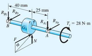
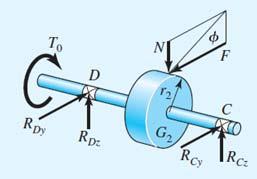
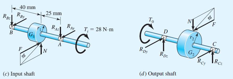
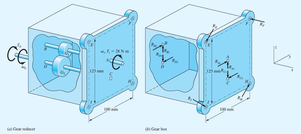
6 Example 3-1 Input shaft Output shaft Gear box

7 Example 3-1

8 Example 3-1

9 Example 3-1
10 Shear Force and Bending Moments in Beams Cut beam at any location x 1 Internal shear force V and bending moment M must ensure equilibrium Sign Conventions
11 Shear Force and Bending Moments in Beams Distributed Load on Beam Distributed load q(x) called load intensity Units of force per unit length Relationships between Load, Shear, and Bending The change in shear force from A to B is equal to the area of the loading diagram between x A and x B. The change in moment from A to B is equal to the area of the shear-force diagram between x A and x B.

12 Example 3-2 Shear Force and Bending Moments in Beams

13 Example 3-3 Shear Force and Bending Moments in Beams

14 Cartesian Stress Component Normal stress is normal to a surface, designated by Shear stress is tangent to a surface, designated by Stress element Represents stress at a point Coordinate directions are arbitrary Choosing coordinates which result in zero shear stress will produce principal stresses
15 Plane-Stress Transformation Equations Cutting plane stress element at an arbitrary angle and balancing stresses gives plane-stress transformation equations
16 Principal Stresses for Plane Stress Principal stresses Principal directions (zero shear stresses) Maximum shear stresses
17 Maximum Shear Stress There are always three principal stresses. One is zero for plane stress. There are always three extreme-value shear stresses. The maximum shear stress is always the greatest of these three If principal stresses are ordered so that 1 > 2 > 3, then max = 1/3
18 Mohr s Circle Diagram Parametric relationship between and (with 2 as parameter) Relationship is a circle with center at C = (, ) = [( x + y )/2, 0 ] R x 2 y 2 2 xy

19 Example 3-4
20 x-y orientation Example 3-4 Principal stress orientation Max shear orientation

21 General Three-Dimensional Stress All stress elements are actually 3-D. Plane stress elements simply have one surface with zero stresses. For cases where there is no stress-free surface, the principal stresses are found from the roots of the cubic equation

22 General Three-Dimensional Stress Always three extreme shear values Maximum Shear Stress is the largest Principal stresses are usually ordered such that 1 > 2 > 3, in which case max = 1/3
23 Homework
24 Homework (a) 8 7 C 0.5 MPa CD 7.5 MPa 2 R MPa MPa Mpa p 2 6 R 9.60 MPa tan cw cw s
25 Homework (b) 9 6 C 1.5 MPa CD 7.5 MPa 2 R MPa MPa MPa p tan 10.9 cw R MPa ccw s
26 Homework (c) 12 4 C 4 MPa CD 8 MPa 2 R MPa MPa MPa 1 8 p 2 7 R MPa tan 69.4 ccw ccw s
27 Homework (d) 6 5 C 0.5 MPa CD 5.5 MPa 2 R MPa MPa MPa p tan ccw R 9.71 MPa cw s
28 Elastic Strain Hooke s law E is Young s modulus, or modulus of elasticity Tension in on direction produces negative strain (contraction) in a perpendicular direction. For axial stress in x direction, The constant of proportionality is Poisson s ratio See Table A-5 for values for common materials.
29 Elastic Strain For a stress element undergoing x, y, and z, simultaneously, Hooke s law for shear: Shear strain G is the change in a right angle of a stress element when subjected to pure shear stress. G is the shear modulus of elasticity or modulus of rigidity. For a linear, isotropic, homogeneous material,
30 Uniformly Distributed Stresses Uniformly distributed stress distribution is often assumed for pure tension, pure compression, or pure shear. For tension and compression, For direct shear (no bending present),

31 Normal Stresses for Beams in Bending Straight beam in positive bending x axis is neutral axis xz plane is neutral plane Neutral axis is coincident with the centroidal axis of the cross section Bending stress varies linearly with distance from neutral axis, y I is the second-area moment about the z axis

32 Normal Stresses for Beams in Bending Maximum bending stress is where y is greatest. c is the magnitude of the greatest y Z = I/c is the section modulus
33 Normal Stresses for Beams in Bending Pure bending (though effects of axial, torsional, and shear loads are often assumed to have minimal effect on bending stress) Material is isotropic and homogeneous Material obeys Hooke s law Beam is initially straight with constant cross section Beam has axis of symmetry in the plane of bending Proportions are such that failure is by bending rather than crushing, wrinkling, or sidewise buckling Plane cross sections remain plane during bending
34 Example 3-5 Dimensions in mm
35 Example 3-5
36 Example 3-5
37 Example 3-5
38 Example 3-5
39 Two-Plane Bending Consider bending in both xy-plane and xz-plane Cross sections with one or two planes of symmetry only For solid circular cross section, the maximum bending stress is

40 Example 3-6

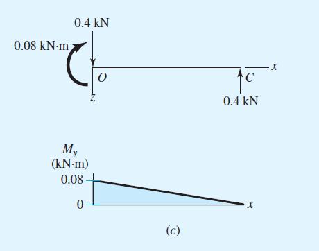
41 Example 3-6

42 Example 3-6 Answer Answer

43 Example 3-6


44 Shear Stress for Beams in Bending

45 Shear Stress for Beams in Bending Transverse shear stress is always accompanied with bending stress.
46 Transverse Shear Stress in a Rectangular Beam

47 Maximum Values of Transverse Shear Stress
48 Significance of Transverse Shear Compared to Bending Example: Cantilever beam, rectangular cross section Maximum shear stress, including bending stress (My/I) and transverse shear stress (VQ/Ib),
49 Significance of Transverse Shear Compared to Bending Critical stress element (largest max ) will always be either Due to bending, on the outer surface (y/c=1), where the transverse shear is zero Or due to transverse shear at the neutral axis (y/c=0), where the bending is zero Transition happens at some critical value of L/h Valid for any cross section that does not increase in width farther away from the neutral axis. Includes round and rectangular solids, but not I beams and channels

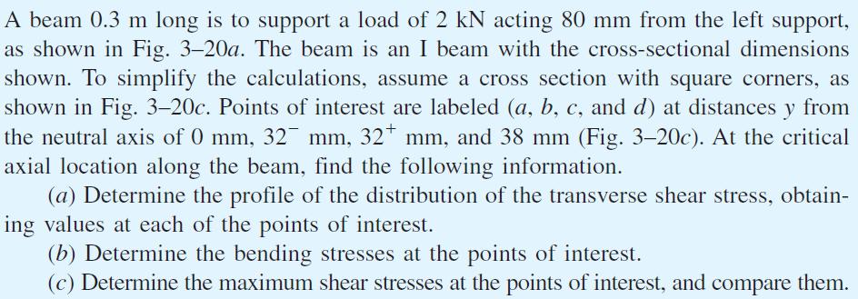
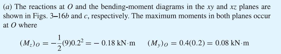
50 Example 3-7

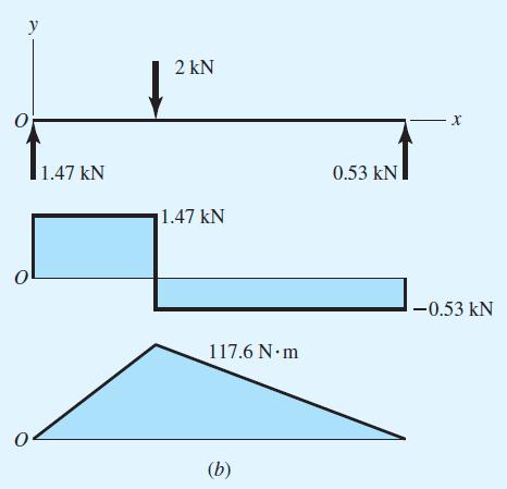
51 Example 3-7

52 Example 3-7

53 Example 3-7

54 Example 3-7

55 Example 3-7
56 Torsion Torque vector a moment vector collinear with axis of a mechanical element A bar subjected to a torque vector is said to be in torsion Angle of twist, in radians, for a solid round bar
57 Torsion For round bar in torsion, torsional shear stress is proportional to the radius r Maximum torsional shear stress is at the outer surface
58 Assumption for Torsion Equations Torsional Equations are only applicable for the following conditions Pure torque Remote from any discontinuities or point of application of torque Material obeys Hooke s law Adjacent cross sections originally plane and parallel remain plane and parallel Radial lines remain straight Depends on axisymmetry, so does not hold true for noncircular cross sections Consequently, only applicable for round cross sections
59 Torsional Shear in Rectangular Section Shear stress does not vary linearly with radial distance for rectangular cross section Shear stress is zero at the corners Maximum shear stress is at the middle of the longest side For rectangular b x c bar, where b is longest side
60 Power, Speed, and Torque Power equals torque times speed A convenient conversion with speed in rpm where H = power, W n = angular velocity, revolutions per minute
61 Power, Speed, and Torque In U.S. Customary units, with unit conversion built in

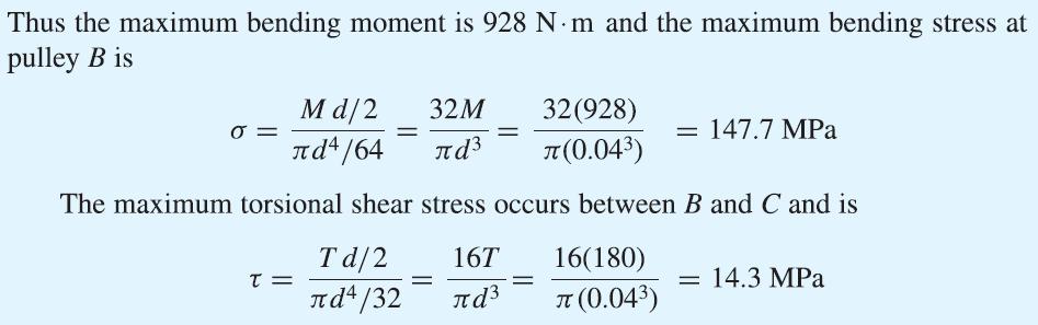
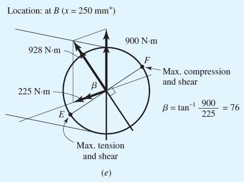
62 Example 3-8
63 Example 3-8 T A = T 2 = 0.13 kn-m M A = 1.3k (0.125) = 0.66 kn-m F = 1.3 kn T c = 1.3k (0.038) = 0.05 kn-m F = 1.3 kn M 2 = T 1 = 0.05kN-m F = 1.3 kn T 1 = 0.05kN-m F = 1.3 kn M 1 = 1.3k (0.1) =0.13 kn-m T 2 = M 1 = 0.13 kn-m

64 Example 3-8
 =0.")
65 Example 3-8 F = 1.3 kn T c = 1.3k (0.038) = 0.05 kn-m T 1 = 0.05kN-m F = 1.3 kn M 1 = 1.3k (0.1) =0.13 kn-m

66 Example 3-8

67 Example 3-8

68 Example 3-8

69 Example 3-8

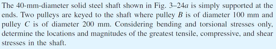
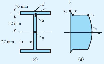
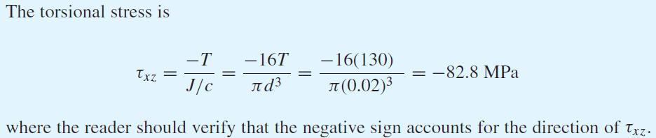
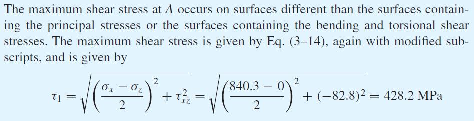
70 Example 3-9

71 Example 3-9

72 Example 3-9

73 Example 3-9

74 Example 3-9

75 Example 3-9
76 Closed Thin-Walled Tubes Wall thickness t << tube radius r (r/t > 10) Product of shear stress times wall thickness is constant Shear stress is inversely proportional to wall thickness Total torque T is Shear flow (q) ( q t constant) A m is the area enclosed by the section median line Fig. 3 25
77 Solving for shear stress Closed Thin-Walled Tubes Angular twist (radians) per unit length L m is the length of the section median line

78 Example 3 10 Fig. 3 26

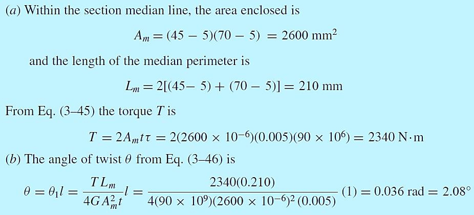
79 Example 3 10

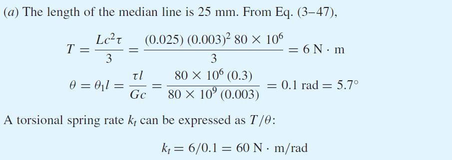
80 Example 3 11 Solution

81 Open Thin-Walled Sections When the median wall line is not closed, the section is said to be an open section Some common open thin-walled sections Fig Torsional shear stress where T = Torque, L = length of median line, c = wall thickness, G = shear modulus, and 1 = angle of twist per unit length

82 Open Thin-Walled Sections Shear stress is inversely proportional to c 2 Angle of twist is inversely proportional to c 3 For small wall thickness, stress and twist can become quite large Example: Compare thin round tube with and without slit Ratio of wall thickness to outside diameter of 0.1 Stress with slit is 12.3 times greater Twist with slit is 61.5 times greater

83 Example 3-12

84 Example 3-12

85 Example 3-12
 Stress")
86 Stress Concentration Localized increase of stress near discontinuities K t is Theoretical (Geometric) Stress Concentration Factor
87 Theoretical Stress Concentration Factor Graphs available for standard configurations See Appendix A-15 and A-16 for common examples Many more in Peterson s Stress-Concentration Factors Note the trend for higher Kt at sharper discontinuity radius, and at greater disruption

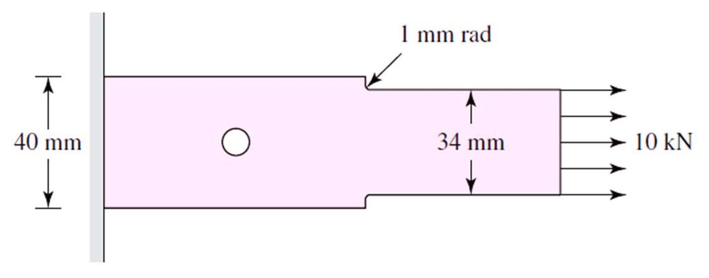
88 Example 3-13
89 Example 3-13
90 Example 3-13
91 Example 3-13
92 Contact Stress Two bodies with curved surfaces pressed together Point or line contact changes to area contact Stresses developed are three-dimensional Called contact stresses or Hertzian stresses Common examples Wheel rolling on rail Mating gear teeth Rolling bearings

93 Spherical Contact Stress Two solid spheres of diameters d 1 and d 2 are pressed together with force F Circular area of contact of radius a Pressure distribution is hemispherical Maximum pressure at the center of contact area
94 Spherical Contact Stress Maximum stresses on the z axis Principal stresses From Mohr s circle, maximum shear stress is

95 Cylindrical Contact Stress Two right circular cylinders with length l and diameters d 1 and d 2 Area of contact is a narrow rectangle of width 2b and length l Pressure distribution is elliptical Half-width b Maximum pressure
96 Cylindrical Contact Stress Maximum stresses on z axis
Tuesday, February 11, Chapter 3. Load and Stress Analysis. Dr. Mohammad Suliman Abuhaiba, PE
 1 Chapter 3 Load and Stress Analysis 2 Chapter Outline Equilibrium & Free-Body Diagrams Shear Force and Bending Moments in Beams Singularity Functions Stress Cartesian Stress Components Mohr s Circle for
Chapter 3. Load and Stress Analysis
 Chapter 3 Load and Stress Analysis 2 Shear Force and Bending Moments in Beams Internal shear force V & bending moment M must ensure equilibrium Fig. 3 2 Sign Conventions for Bending and Shear Fig. 3 3
UNIT 1 STRESS STRAIN AND DEFORMATION OF SOLIDS, STATES OF STRESS 1. Define stress. When an external force acts on a body, it undergoes deformation.
 UNIT 1 STRESS STRAIN AND DEFORMATION OF SOLIDS, STATES OF STRESS 1. Define stress. When an external force acts on a body, it undergoes deformation. At the same time the body resists deformation. The magnitude
Advanced Structural Analysis EGF Section Properties and Bending
 Advanced Structural Analysis EGF316 3. Section Properties and Bending 3.1 Loads in beams When we analyse beams, we need to consider various types of loads acting on them, for example, axial forces, shear
Mechanics of Materials II. Chapter III. A review of the fundamental formulation of stress, strain, and deflection
 Mechanics of Materials II Chapter III A review of the fundamental formulation of stress, strain, and deflection Outline Introduction Assumtions and limitations Axial loading Torsion of circular shafts
Mechanical Design in Optical Engineering
 Torsion Torsion: Torsion refers to the twisting of a structural member that is loaded by couples (torque) that produce rotation about the member s longitudinal axis. In other words, the member is loaded
(48) CHAPTER 3: TORSION
 CHAPTER 3: TORSION") (48) CHAPTER 3: TORSION Introduction: In this chapter structural members and machine parts that are in torsion will be considered. More specifically, you will analyze the stresses and strains in members
(48) CHAPTER 3: TORSION Introduction: In this chapter structural members and machine parts that are in torsion will be considered. More specifically, you will analyze the stresses and strains in members
CHAPTER -6- BENDING Part -1-
 Ishik University / Sulaimani Civil Engineering Department Mechanics of Materials CE 211 CHAPTER -6- BENDING Part -1-1 CHAPTER -6- Bending Outlines of this chapter: 6.1. Chapter Objectives 6.2. Shear and
COURSE TITLE : APPLIED MECHANICS & STRENGTH OF MATERIALS COURSE CODE : 4017 COURSE CATEGORY : A PERIODS/WEEK : 6 PERIODS/ SEMESTER : 108 CREDITS : 5
 COURSE TITLE : APPLIED MECHANICS & STRENGTH OF MATERIALS COURSE CODE : 4017 COURSE CATEGORY : A PERIODS/WEEK : 6 PERIODS/ SEMESTER : 108 CREDITS : 5 TIME SCHEDULE MODULE TOPICS PERIODS 1 Simple stresses
STRESS STRAIN AND DEFORMATION OF SOLIDS, STATES OF STRESS
 1 UNIT I STRESS STRAIN AND DEFORMATION OF SOLIDS, STATES OF STRESS 1. Define: Stress When an external force acts on a body, it undergoes deformation. At the same time the body resists deformation. The
6. Bending CHAPTER OBJECTIVES
 CHAPTER OBJECTIVES Determine stress in members caused by bending Discuss how to establish shear and moment diagrams for a beam or shaft Determine largest shear and moment in a member, and specify where
QUESTION BANK DEPARTMENT: CIVIL SEMESTER: III SUBJECT CODE: CE2201 SUBJECT NAME: MECHANICS OF SOLIDS UNIT 1- STRESS AND STRAIN PART A
 DEPARTMENT: CIVIL SUBJECT CODE: CE2201 QUESTION BANK SEMESTER: III SUBJECT NAME: MECHANICS OF SOLIDS UNIT 1- STRESS AND STRAIN PART A (2 Marks) 1. Define longitudinal strain and lateral strain. 2. State
Torsion of shafts with circular symmetry
 orsion of shafts with circular symmetry Introduction Consider a uniform bar which is subject to a torque, eg through the action of two forces F separated by distance d, hence Fd orsion is the resultant
QUESTION BANK SEMESTER: III SUBJECT NAME: MECHANICS OF SOLIDS
 QUESTION BANK SEMESTER: III SUBJECT NAME: MECHANICS OF SOLIDS UNIT 1- STRESS AND STRAIN PART A (2 Marks) 1. Define longitudinal strain and lateral strain. 2. State Hooke s law. 3. Define modular ratio,
: APPLIED MECHANICS & STRENGTH OF MATERIALS COURSE CODE : 4021 COURSE CATEGORY : A PERIODS/ WEEK : 5 PERIODS/ SEMESTER : 75 CREDIT : 5 TIME SCHEDULE
 COURSE TITLE : APPLIED MECHANICS & STRENGTH OF MATERIALS COURSE CODE : 4021 COURSE CATEGORY : A PERIODS/ WEEK : 5 PERIODS/ SEMESTER : 75 CREDIT : 5 TIME SCHEDULE MODULE TOPIC PERIODS 1 Simple stresses
R13. II B. Tech I Semester Regular Examinations, Jan MECHANICS OF SOLIDS (Com. to ME, AME, AE, MTE) PART-A
 PART-A") SET - 1 II B. Tech I Semester Regular Examinations, Jan - 2015 MECHANICS OF SOLIDS (Com. to ME, AME, AE, MTE) Time: 3 hours Max. Marks: 70 Note: 1. Question Paper consists of two parts (Part-A and Part-B)
SET - 1 II B. Tech I Semester Regular Examinations, Jan - 2015 MECHANICS OF SOLIDS (Com. to ME, AME, AE, MTE) Time: 3 hours Max. Marks: 70 Note: 1. Question Paper consists of two parts (Part-A and Part-B)
[8] Bending and Shear Loading of Beams
![[8] Bending and Shear Loading of Beams](/thumbs/92/110949676.jpg "[8] Bending and Shear Loading of Beams") [8] Bending and Shear Loading of Beams Page 1 of 28 [8] Bending and Shear Loading of Beams [8.1] Bending of Beams (will not be covered in class) [8.2] Bending Strain and Stress [8.3] Shear in Straight
[8] Bending and Shear Loading of Beams Page 1 of 28 [8] Bending and Shear Loading of Beams [8.1] Bending of Beams (will not be covered in class) [8.2] Bending Strain and Stress [8.3] Shear in Straight
Structural Analysis I Chapter 4 - Torsion TORSION
 ORSION orsional stress results from the action of torsional or twisting moments acting about the longitudinal axis of a shaft. he effect of the application of a torsional moment, combined with appropriate
Mechanical Engineering Ph.D. Preliminary Qualifying Examination Solid Mechanics February 25, 2002
 student personal identification (ID) number on each sheet. Do not write your name on any sheet. #1. A homogeneous, isotropic, linear elastic bar has rectangular cross sectional area A, modulus of elasticity
CHAPTER THREE SYMMETRIC BENDING OF CIRCLE PLATES
 CHAPTER THREE SYMMETRIC BENDING OF CIRCLE PLATES * Governing equations in beam and plate bending ** Solution by superposition 1.1 From Beam Bending to Plate Bending 1.2 Governing Equations For Symmetric
KINGS COLLEGE OF ENGINEERING DEPARTMENT OF MECHANICAL ENGINEERING QUESTION BANK. Subject code/name: ME2254/STRENGTH OF MATERIALS Year/Sem:II / IV
 KINGS COLLEGE OF ENGINEERING DEPARTMENT OF MECHANICAL ENGINEERING QUESTION BANK Subject code/name: ME2254/STRENGTH OF MATERIALS Year/Sem:II / IV UNIT I STRESS, STRAIN DEFORMATION OF SOLIDS PART A (2 MARKS)
NAME: Given Formulae: Law of Cosines: Law of Sines:
 NME: Given Formulae: Law of Cosines: EXM 3 PST PROBLEMS (LESSONS 21 TO 28) 100 points Thursday, November 16, 2017, 7pm to 9:30, Room 200 You are allowed to use a calculator and drawing equipment, only.
Chapter 5: Torsion. 1. Torsional Deformation of a Circular Shaft 2. The Torsion Formula 3. Power Transmission 4. Angle of Twist CHAPTER OBJECTIVES
 CHAPTER OBJECTIVES Chapter 5: Torsion Discuss effects of applying torsional loading to a long straight member (shaft or tube) Determine stress distribution within the member under torsional load Determine
[5] Stress and Strain
![[5] Stress and Strain](/thumbs/95/123344550.jpg "[5] Stress and Strain") [5] Stress and Strain Page 1 of 34 [5] Stress and Strain [5.1] Internal Stress of Solids [5.2] Design of Simple Connections (will not be covered in class) [5.3] Deformation and Strain [5.4] Hooke s Law
[5] Stress and Strain Page 1 of 34 [5] Stress and Strain [5.1] Internal Stress of Solids [5.2] Design of Simple Connections (will not be covered in class) [5.3] Deformation and Strain [5.4] Hooke s Law
D : SOLID MECHANICS. Q. 1 Q. 9 carry one mark each.
 GTE 2016 Q. 1 Q. 9 carry one mark each. D : SOLID MECHNICS Q.1 single degree of freedom vibrating system has mass of 5 kg, stiffness of 500 N/m and damping coefficient of 100 N-s/m. To make the system
Stress Analysis Lecture 3 ME 276 Spring Dr./ Ahmed Mohamed Nagib Elmekawy
 Stress Analysis Lecture 3 ME 276 Spring 2017-2018 Dr./ Ahmed Mohamed Nagib Elmekawy Axial Stress 2 Beam under the action of two tensile forces 3 Beam under the action of two tensile forces 4 Shear Stress
PURE BENDING. If a simply supported beam carries two point loads of 10 kn as shown in the following figure, pure bending occurs at segment BC.
 BENDING STRESS The effect of a bending moment applied to a cross-section of a beam is to induce a state of stress across that section. These stresses are known as bending stresses and they act normally
Chapter 5 Torsion STRUCTURAL MECHANICS: CE203. Notes are based on Mechanics of Materials: by R. C. Hibbeler, 7th Edition, Pearson
 STRUCTURAL MECHANICS: CE203 Chapter 5 Torsion Notes are based on Mechanics of Materials: by R. C. Hibbeler, 7th Edition, Pearson Dr B. Achour & Dr Eng. K. El-kashif Civil Engineering Department, University
EMA 3702 Mechanics & Materials Science (Mechanics of Materials) Chapter 3 Torsion
 Chapter 3 Torsion") EMA 3702 Mechanics & Materials Science (Mechanics of Materials) Chapter 3 Torsion Introduction Stress and strain in components subjected to torque T Circular Cross-section shape Material Shaft design Non-circular
EMA 3702 Mechanics & Materials Science (Mechanics of Materials) Chapter 3 Torsion Introduction Stress and strain in components subjected to torque T Circular Cross-section shape Material Shaft design Non-circular
CE6306 STRENGTH OF MATERIALS TWO MARK QUESTIONS WITH ANSWERS ACADEMIC YEAR
 CE6306 STRENGTH OF MATERIALS TWO MARK QUESTIONS WITH ANSWERS ACADEMIC YEAR 2014-2015 UNIT - 1 STRESS, STRAIN AND DEFORMATION OF SOLIDS PART- A 1. Define tensile stress and tensile strain. The stress induced
MECHANICS OF MATERIALS
 2009 The McGraw-Hill Companies, Inc. All rights reserved. Fifth SI Edition CHAPTER 3 MECHANICS OF MATERIALS Ferdinand P. Beer E. Russell Johnston, Jr. John T. DeWolf David F. Mazurek Torsion Lecture Notes:
MECH 401 Mechanical Design Applications
 MECH 401 Mechanical Design Applications Dr. M. O Malley Master Notes Spring 008 Dr. D. M. McStravick Rice University Updates HW 1 due Thursday (1-17-08) Last time Introduction Units Reliability engineering
Lecture Slides. Chapter 4. Deflection and Stiffness. The McGraw-Hill Companies 2012
 Lecture Slides Chapter 4 Deflection and Stiffness The McGraw-Hill Companies 2012 Chapter Outline Force vs Deflection Elasticity property of a material that enables it to regain its original configuration
Sub. Code:
 Important Instructions to examiners: ) The answers should be examined by key words and not as word-to-word as given in the model answer scheme. ) The model answer and the answer written by candidate may
PES Institute of Technology
 PES Institute of Technology Bangalore south campus, Bangalore-5460100 Department of Mechanical Engineering Faculty name : Madhu M Date: 29/06/2012 SEM : 3 rd A SEC Subject : MECHANICS OF MATERIALS Subject
ME Final Exam. PROBLEM NO. 4 Part A (2 points max.) M (x) y. z (neutral axis) beam cross-sec+on. 20 kip ft. 0.2 ft. 10 ft. 0.1 ft.
 M (x) y. z (neutral axis) beam cross-sec+on. 20 kip ft. 0.2 ft. 10 ft. 0.1 ft.") ME 323 - Final Exam Name December 15, 2015 Instructor (circle) PROEM NO. 4 Part A (2 points max.) Krousgrill 11:30AM-12:20PM Ghosh 2:30-3:20PM Gonzalez 12:30-1:20PM Zhao 4:30-5:20PM M (x) y 20 kip ft 0.2
ME 323 - Final Exam Name December 15, 2015 Instructor (circle) PROEM NO. 4 Part A (2 points max.) Krousgrill 11:30AM-12:20PM Ghosh 2:30-3:20PM Gonzalez 12:30-1:20PM Zhao 4:30-5:20PM M (x) y 20 kip ft 0.2
Mechanics of Materials Primer
 Mechanics of Materials rimer Notation: A = area (net = with holes, bearing = in contact, etc...) b = total width of material at a horizontal section d = diameter of a hole D = symbol for diameter E = modulus
STRENGTH OF MATERIALS-I. Unit-1. Simple stresses and strains
 STRENGTH OF MATERIALS-I Unit-1 Simple stresses and strains 1. What is the Principle of surveying 2. Define Magnetic, True & Arbitrary Meridians. 3. Mention different types of chains 4. Differentiate between
2. (a) Explain different types of wing structures. (b) Explain the advantages and disadvantages of different materials used for aircraft
 Explain different types of wing structures. (b) Explain the advantages and disadvantages of different materials used for aircraft") Code No: 07A62102 R07 Set No. 2 III B.Tech II Semester Regular/Supplementary Examinations,May 2010 Aerospace Vehicle Structures -II Aeronautical Engineering Time: 3 hours Max Marks: 80 Answer any FIVE
Code No: 07A62102 R07 Set No. 2 III B.Tech II Semester Regular/Supplementary Examinations,May 2010 Aerospace Vehicle Structures -II Aeronautical Engineering Time: 3 hours Max Marks: 80 Answer any FIVE
3 Hours/100 Marks Seat No.
 *17304* 17304 14115 3 Hours/100 Marks Seat No. Instructions : (1) All questions are compulsory. (2) Illustrate your answers with neat sketches wherever necessary. (3) Figures to the right indicate full
UNIT- I Thin plate theory, Structural Instability:
 UNIT- I Thin plate theory, Structural Instability: Analysis of thin rectangular plates subject to bending, twisting, distributed transverse load, combined bending and in-plane loading Thin plates having
COURSE TITLE : THEORY OF STRUCTURES -I COURSE CODE : 3013 COURSE CATEGORY : B PERIODS/WEEK : 6 PERIODS/SEMESTER: 90 CREDITS : 6
 COURSE TITLE : THEORY OF STRUCTURES -I COURSE CODE : 0 COURSE CATEGORY : B PERIODS/WEEK : 6 PERIODS/SEMESTER: 90 CREDITS : 6 TIME SCHEDULE Module Topics Period Moment of forces Support reactions Centre
Downloaded from Downloaded from / 1
 PURWANCHAL UNIVERSITY III SEMESTER FINAL EXAMINATION-2002 LEVEL : B. E. (Civil) SUBJECT: BEG256CI, Strength of Material Full Marks: 80 TIME: 03:00 hrs Pass marks: 32 Candidates are required to give their
March 24, Chapter 4. Deflection and Stiffness. Dr. Mohammad Suliman Abuhaiba, PE
 Chapter 4 Deflection and Stiffness 1 2 Chapter Outline Spring Rates Tension, Compression, and Torsion Deflection Due to Bending Beam Deflection Methods Beam Deflections by Superposition Strain Energy Castigliano
[7] Torsion. [7.1] Torsion. [7.2] Statically Indeterminate Torsion. [7] Torsion Page 1 of 21
![[7] Torsion. [7.1] Torsion. [7.2] Statically Indeterminate Torsion. [7] Torsion Page 1 of 21](/thumbs/88/115835122.jpg "[7] Torsion. [7.1] Torsion. [7.2] Statically Indeterminate Torsion. [7] Torsion Page 1 of 21") [7] Torsion Page 1 of 21 [7] Torsion [7.1] Torsion [7.2] Statically Indeterminate Torsion [7] Torsion Page 2 of 21 [7.1] Torsion SHEAR STRAIN DUE TO TORSION 1) A shaft with a circular cross section is
[7] Torsion Page 1 of 21 [7] Torsion [7.1] Torsion [7.2] Statically Indeterminate Torsion [7] Torsion Page 2 of 21 [7.1] Torsion SHEAR STRAIN DUE TO TORSION 1) A shaft with a circular cross section is
4. SHAFTS. A shaft is an element used to transmit power and torque, and it can support
 4. SHAFTS A shaft is an element used to transmit power and torque, and it can support reverse bending (fatigue). Most shafts have circular cross sections, either solid or tubular. The difference between
CHAPTER 4: BENDING OF BEAMS
 (74) CHAPTER 4: BENDING OF BEAMS This chapter will be devoted to the analysis of prismatic members subjected to equal and opposite couples M and M' acting in the same longitudinal plane. Such members are
CE 221: MECHANICS OF SOLIDS I CHAPTER 1: STRESS. Dr. Krisada Chaiyasarn Department of Civil Engineering, Faculty of Engineering Thammasat university
 CE 221: MECHANICS OF SOLIDS I CHAPTER 1: STRESS By Dr. Krisada Chaiyasarn Department of Civil Engineering, Faculty of Engineering Thammasat university Agenda Introduction to your lecturer Introduction
MECHANICS OF MATERIALS
 GE SI CHAPTER 3 MECHANICS OF MATERIALS Ferdinand P. Beer E. Russell Johnston, Jr. John T. DeWolf David F. Mazurek Torsion Lecture Notes: J. Walt Oler Texas Tech University Torsional Loads on Circular Shafts
7.6 Stress in symmetrical elastic beam transmitting both shear force and bending moment
 7.6 Stress in symmetrical elastic beam transmitting both shear force and bending moment à It is more difficult to obtain an exact solution to this problem since the presence of the shear force means that
3. BEAMS: STRAIN, STRESS, DEFLECTIONS
 3. BEAMS: STRAIN, STRESS, DEFLECTIONS The beam, or flexural member, is frequently encountered in structures and machines, and its elementary stress analysis constitutes one of the more interesting facets
Stresses in Curved Beam
 Stresses in Curved Beam Consider a curved beam subjected to bending moment M b as shown in the figure. The distribution of stress in curved flexural member is determined by using the following assumptions:
PDDC 1 st Semester Civil Engineering Department Assignments of Mechanics of Solids [ ] Introduction, Fundamentals of Statics
![PDDC 1 st Semester Civil Engineering Department Assignments of Mechanics of Solids [ ] Introduction, Fundamentals of Statics](/thumbs/92/109382806.jpg "PDDC 1 st Semester Civil Engineering Department Assignments of Mechanics of Solids [ ] Introduction, Fundamentals of Statics") Page1 PDDC 1 st Semester Civil Engineering Department Assignments of Mechanics of Solids [2910601] Introduction, Fundamentals of Statics 1. Differentiate between Scalar and Vector quantity. Write S.I.
Page1 PDDC 1 st Semester Civil Engineering Department Assignments of Mechanics of Solids [2910601] Introduction, Fundamentals of Statics 1. Differentiate between Scalar and Vector quantity. Write S.I.
CIVL222 STRENGTH OF MATERIALS. Chapter 6. Torsion
 CIVL222 STRENGTH OF MATERIALS Chapter 6 Torsion Definition Torque is a moment that tends to twist a member about its longitudinal axis. Slender members subjected to a twisting load are said to be in torsion.
VYSOKÁ ŠKOLA BÁŇSKÁ TECHNICKÁ UNIVERZITA OSTRAVA
 VYSOKÁ ŠKOLA BÁŇSKÁ TECHNICKÁ UNIVERZITA OSTRAVA FAKULTA METALURGIE A MATERIÁLOVÉHO INŽENÝRSTVÍ APPLIED MECHANICS Study Support Leo Václavek Ostrava 2015 Title:Applied Mechanics Code: Author: doc. Ing.
PERIYAR CENTENARY POLYTECHNIC COLLEGE PERIYAR NAGAR - VALLAM THANJAVUR. DEPARTMENT OF MECHANICAL ENGINEERING QUESTION BANK
 PERIYAR CENTENARY POLYTECHNIC COLLEGE PERIYAR NAGAR - VALLAM - 613 403 - THANJAVUR. DEPARTMENT OF MECHANICAL ENGINEERING QUESTION BANK Sub : Strength of Materials Year / Sem: II / III Sub Code : MEB 310
Consider an elastic spring as shown in the Fig.2.4. When the spring is slowly
 .3 Strain Energy Consider an elastic spring as shown in the Fig..4. When the spring is slowly pulled, it deflects by a small amount u 1. When the load is removed from the spring, it goes back to the original
DEPARTMENT OF MECHANICAL ENIGINEERING, UNIVERSITY OF ENGINEERING & TECHNOLOGY LAHORE (KSK CAMPUS).
.") DEPARTMENT OF MECHANICAL ENIGINEERING, UNIVERSITY OF ENGINEERING & TECHNOLOGY LAHORE (KSK CAMPUS). Lab Director: Coordinating Staff: Mr. Muhammad Farooq (Lecturer) Mr. Liaquat Qureshi (Lab Supervisor)
DEPARTMENT OF MECHANICAL ENIGINEERING, UNIVERSITY OF ENGINEERING & TECHNOLOGY LAHORE (KSK CAMPUS). Lab Director: Coordinating Staff: Mr. Muhammad Farooq (Lecturer) Mr. Liaquat Qureshi (Lab Supervisor)
7.4 The Elementary Beam Theory
 7.4 The Elementary Beam Theory In this section, problems involving long and slender beams are addressed. s with pressure vessels, the geometry of the beam, and the specific type of loading which will be
Stress and Strain ( , 3.14) MAE 316 Strength of Mechanical Components NC State University Department of Mechanical & Aerospace Engineering
 MAE 316 Strength of Mechanical Components NC State University Department of Mechanical & Aerospace Engineering") (3.8-3.1, 3.14) MAE 316 Strength of Mechanical Components NC State Universit Department of Mechanical & Aerospace Engineering 1 Introduction MAE 316 is a continuation of MAE 314 (solid mechanics) Review
(3.8-3.1, 3.14) MAE 316 Strength of Mechanical Components NC State Universit Department of Mechanical & Aerospace Engineering 1 Introduction MAE 316 is a continuation of MAE 314 (solid mechanics) Review
2. Rigid bar ABC supports a weight of W = 50 kn. Bar ABC is pinned at A and supported at B by rod (1). What is the axial force in rod (1)?
. What is the axial force in rod (1)?") IDE 110 S08 Test 1 Name: 1. Determine the internal axial forces in segments (1), (2) and (3). (a) N 1 = kn (b) N 2 = kn (c) N 3 = kn 2. Rigid bar ABC supports a weight of W = 50 kn. Bar ABC is pinned at
IDE 110 S08 Test 1 Name: 1. Determine the internal axial forces in segments (1), (2) and (3). (a) N 1 = kn (b) N 2 = kn (c) N 3 = kn 2. Rigid bar ABC supports a weight of W = 50 kn. Bar ABC is pinned at
INSTITUTE OF AERONAUTICAL ENGINEERING (Autonomous) Dundigal, Hyderabad
 Dundigal, Hyderabad") INSTITUTE OF AERONAUTICAL ENGINEERING (Autonomous) Dundigal, Hyderabad -00 04 CIVIL ENGINEERING QUESTION BANK Course Name : STRENGTH OF MATERIALS II Course Code : A404 Class : II B. Tech II Semester Section
INSTITUTE OF AERONAUTICAL ENGINEERING (Autonomous) Dundigal, Hyderabad -00 04 CIVIL ENGINEERING QUESTION BANK Course Name : STRENGTH OF MATERIALS II Course Code : A404 Class : II B. Tech II Semester Section
twenty one concrete construction: shear & deflection ARCHITECTURAL STRUCTURES: FORM, BEHAVIOR, AND DESIGN DR. ANNE NICHOLS SUMMER 2014 lecture
 ARCHITECTURAL STRUCTURES: FORM, BEHAVIOR, AND DESIGN DR. ANNE NICHOLS SUMMER 2014 lecture twenty one concrete construction: Copyright Kirk Martini shear & deflection Concrete Shear 1 Shear in Concrete
Unit Workbook 1 Level 4 ENG U8 Mechanical Principles 2018 UniCourse Ltd. All Rights Reserved. Sample
 Pearson BTEC Levels 4 Higher Nationals in Engineering (RQF) Unit 8: Mechanical Principles Unit Workbook 1 in a series of 4 for this unit Learning Outcome 1 Static Mechanical Systems Page 1 of 23 1.1 Shafts
MECHANICS OF MATERIALS
 STATICS AND MECHANICS OF MATERIALS Ferdinand P. Beer E. Russell Johnston, Jr, John T. DeWolf David E Mazurek \Cawect Mc / iur/» Craw SugomcT Hilt Introduction 1 1.1 What is Mechanics? 2 1.2 Fundamental
The problem of transmitting a torque or rotary motion from one plane to another is frequently encountered in machine design.
 CHAPER ORSION ORSION orsion refers to the twisting of a structural member when it is loaded by moments/torques that produce rotation about the longitudinal axis of the member he problem of transmitting
Strength of Materials II (Mechanics of Materials) (SI Units) Dr. Ashraf Alfeehan
 (SI Units) Dr. Ashraf Alfeehan") Strength of Materials II (Mechanics of Materials) (SI Units) Dr. Ashraf Alfeehan 2017-2018 Mechanics of Material II Text Books Mechanics of Materials, 10th edition (SI version), by: R. C. Hibbeler, 2017
Strength of Materials II (Mechanics of Materials) (SI Units) Dr. Ashraf Alfeehan 2017-2018 Mechanics of Material II Text Books Mechanics of Materials, 10th edition (SI version), by: R. C. Hibbeler, 2017
Chapter 4 Deflection and Stiffness
 Chapter 4 Deflection and Stiffness Asst. Prof. Dr. Supakit Rooppakhun Chapter Outline Deflection and Stiffness 4-1 Spring Rates 4-2 Tension, Compression, and Torsion 4-3 Deflection Due to Bending 4-4 Beam
INTRODUCTION TO STRAIN
 SIMPLE STRAIN INTRODUCTION TO STRAIN In general terms, Strain is a geometric quantity that measures the deformation of a body. There are two types of strain: normal strain: characterizes dimensional changes,
8. Combined Loadings
 CHAPTER OBJECTIVES qanalyze the stress developed in thin-walled pressure vessels qreview the stress analysis developed in previous chapters regarding axial load, torsion, bending and shear qdiscuss the
Samantha Ramirez, MSE. Stress. The intensity of the internal force acting on a specific plane (area) passing through a point. F 2
 passing through a point. F 2") Samantha Ramirez, MSE Stress The intensity of the internal force acting on a specific plane (area) passing through a point. Δ ΔA Δ z Δ 1 2 ΔA Δ x Δ y ΔA is an infinitesimal size area with a uniform force
Samantha Ramirez, MSE Stress The intensity of the internal force acting on a specific plane (area) passing through a point. Δ ΔA Δ z Δ 1 2 ΔA Δ x Δ y ΔA is an infinitesimal size area with a uniform force
Mechanical Properties of Materials
 Mechanical Properties of Materials Strains Material Model Stresses Learning objectives Understand the qualitative and quantitative description of mechanical properties of materials. Learn the logic of
Engineering Science OUTCOME 1 - TUTORIAL 4 COLUMNS
 Unit 2: Unit code: QCF Level: Credit value: 15 Engineering Science L/601/10 OUTCOME 1 - TUTORIAL COLUMNS 1. Be able to determine the behavioural characteristics of elements of static engineering systems
Structural Dynamics Lecture Eleven: Dynamic Response of MDOF Systems: (Chapter 11) By: H. Ahmadian
 By: H. Ahmadian") Structural Dynamics Lecture Eleven: Dynamic Response of MDOF Systems: (Chapter 11) By: H. Ahmadian ahmadian@iust.ac.ir Dynamic Response of MDOF Systems: Mode-Superposition Method Mode-Superposition Method:
Structural Dynamics Lecture Eleven: Dynamic Response of MDOF Systems: (Chapter 11) By: H. Ahmadian ahmadian@iust.ac.ir Dynamic Response of MDOF Systems: Mode-Superposition Method Mode-Superposition Method:
OUTCOME 1 - TUTORIAL 3 BENDING MOMENTS. You should judge your progress by completing the self assessment exercises. CONTENTS
 Unit 2: Unit code: QCF Level: 4 Credit value: 15 Engineering Science L/601/1404 OUTCOME 1 - TUTORIAL 3 BENDING MOMENTS 1. Be able to determine the behavioural characteristics of elements of static engineering
IDE 110 Mechanics of Materials Spring 2006 Final Examination FOR GRADING ONLY
 Spring 2006 Final Examination STUDENT S NAME (please print) STUDENT S SIGNATURE STUDENT NUMBER IDE 110 CLASS SECTION INSTRUCTOR S NAME Do not turn this page until instructed to start. Write your name on
Members Subjected to Torsional Loads
 Members Subjected to Torsional Loads Torsion of circular shafts Definition of Torsion: Consider a shaft rigidly clamped at one end and twisted at the other end by a torque T = F.d applied in a plane perpendicular
3 2 6 Solve the initial value problem u ( t) 3. a- If A has eigenvalues λ =, λ = 1 and corresponding eigenvectors 1
 3. a- If A has eigenvalues λ =, λ = 1 and corresponding eigenvectors 1") Math Problem a- If A has eigenvalues λ =, λ = 1 and corresponding eigenvectors 1 3 6 Solve the initial value problem u ( t) = Au( t) with u (0) =. 3 1 u 1 =, u 1 3 = b- True or false and why 1. if A is
Math Problem a- If A has eigenvalues λ =, λ = 1 and corresponding eigenvectors 1 3 6 Solve the initial value problem u ( t) = Au( t) with u (0) =. 3 1 u 1 =, u 1 3 = b- True or false and why 1. if A is
MECE 3321 MECHANICS OF SOLIDS CHAPTER 1
 MECE 3321 MECHANICS O SOLIDS CHAPTER 1 Samantha Ramirez, MSE WHAT IS MECHANICS O MATERIALS? Rigid Bodies Statics Dynamics Mechanics Deformable Bodies Solids/Mech. Of Materials luids 1 WHAT IS MECHANICS
MECH 344/X Machine Element Design
 1 MECH 344/X Machine Element Design Time: M 14:45-17:30 Lecture 2 Contents of today's lecture Introduction to Static Stresses Axial, Shear and Torsional Loading Bending in Straight and Curved Beams Transverse
4. BEAMS: CURVED, COMPOSITE, UNSYMMETRICAL
 4. BEMS: CURVED, COMPOSITE, UNSYMMETRICL Discussions of beams in bending are usually limited to beams with at least one longitudinal plane of symmetry with the load applied in the plane of symmetry or
MARKS DISTRIBUTION AS PER CHAPTER (QUESTION ASKED IN GTU EXAM) Name Of Chapter. Applications of. Friction. Centroid & Moment.
 Name Of Chapter. Applications of. Friction. Centroid & Moment.") Introduction Fundamentals of statics Applications of fundamentals of statics Friction Centroid & Moment of inertia Simple Stresses & Strain Stresses in Beam Torsion Principle Stresses DEPARTMENT OF CIVIL
Introduction Fundamentals of statics Applications of fundamentals of statics Friction Centroid & Moment of inertia Simple Stresses & Strain Stresses in Beam Torsion Principle Stresses DEPARTMENT OF CIVIL
Torsion Stresses in Tubes and Rods
 Torsion Stresses in Tubes and Rods This initial analysis is valid only for a restricted range of problem for which the assumptions are: Rod is initially straight. Rod twists without bending. Material is
MECHANICS OF MATERIALS. Prepared by Engr. John Paul Timola
 MECHANICS OF MATERIALS Prepared by Engr. John Paul Timola Mechanics of materials branch of mechanics that studies the internal effects of stress and strain in a solid body. stress is associated with the
18.Define the term modulus of resilience. May/June Define Principal Stress. 20. Define Hydrostatic Pressure.
 CE6306 STREGNTH OF MATERIALS Question Bank Unit-I STRESS, STRAIN, DEFORMATION OF SOLIDS PART-A 1. Define Poison s Ratio May/June 2009 2. What is thermal stress? May/June 2009 3. Estimate the load carried
PROBLEM 3.3 ( )(45 10 ) T 5.17 kn m. A c c. 2 J c, (2)( ) 2 ( ) mm ( )
(45 10 ) T 5.17 kn m. A c c. 2 J c, (2)( ) 2 ( ) mm ( )") 0 mm PROEM..4 m 45 mm (a) Determine the torque that causes a maximum shearing stress of 45 MPa in the hollow cylindrical steel shaft shown. Determine the maximum shearing stress caused by the same torque
0 mm PROEM..4 m 45 mm (a) Determine the torque that causes a maximum shearing stress of 45 MPa in the hollow cylindrical steel shaft shown. Determine the maximum shearing stress caused by the same torque
Physical Science and Engineering. Course Information. Course Number: ME 100
 Physical Science and Engineering Course Number: ME 100 Course Title: Course Information Basic Principles of Mechanics Academic Semester: Fall Academic Year: 2016-2017 Semester Start Date: 8/21/2016 Semester
CHAPTER 6: Shearing Stresses in Beams
 (130) CHAPTER 6: Shearing Stresses in Beams When a beam is in pure bending, the only stress resultants are the bending moments and the only stresses are the normal stresses acting on the cross sections.
2. Polar moment of inertia As stated above, the polar second moment of area, J is defined as. Sample copy
 GATE PATHSHALA - 91. Polar moment of inertia As stated above, the polar second moment of area, is defined as z π r dr 0 R r π R π D For a solid shaft π (6) QP 0 π d Solid shaft π d Hollow shaft, " ( do
BE Semester- I ( ) Question Bank (MECHANICS OF SOLIDS)
 Question Bank (MECHANICS OF SOLIDS)") BE Semester- I ( ) Question Bank (MECHANICS OF SOLIDS) All questions carry equal marks(10 marks) Q.1 (a) Write the SI units of following quantities and also mention whether it is scalar or vector: (i)
BE Semester- I ( ) Question Bank (MECHANICS OF SOLIDS) All questions carry equal marks(10 marks) Q.1 (a) Write the SI units of following quantities and also mention whether it is scalar or vector: (i)
Purpose of this Guide: To thoroughly prepare students for the exact types of problems that will be on Exam 3.
 ES230 STRENGTH OF MTERILS Exam 3 Study Guide Exam 3: Wednesday, March 8 th in-class Updated 3/3/17 Purpose of this Guide: To thoroughly prepare students for the exact types of problems that will be on
SRI CHANDRASEKHARENDRA SARASWATHI VISWA MAHAVIDHYALAYA
 SRI CHANDRASEKHARENDRA SARASWATHI VISWA MAHAVIDHYALAYA (Declared as Deemed-to-be University under Section 3 of the UGC Act, 1956, Vide notification No.F.9.9/92-U-3 dated 26 th May 1993 of the Govt. of
Strength of Materials Prof. S.K.Bhattacharya Dept. of Civil Engineering, I.I.T., Kharagpur Lecture No.26 Stresses in Beams-I
 Strength of Materials Prof. S.K.Bhattacharya Dept. of Civil Engineering, I.I.T., Kharagpur Lecture No.26 Stresses in Beams-I Welcome to the first lesson of the 6th module which is on Stresses in Beams
MAHALAKSHMI ENGINEERING COLLEGE
 MAHALAKSHMI ENGINEERING COLLEGE TIRUCHIRAALLI - 6113. QUESTION WITH ANSWERS DEARTMENT : CIVIL SEMESTER: V SUB.CODE/ NAME: CE 5 / Strength of Materials UNIT 3 COULMNS ART - A ( marks) 1. Define columns
(Refer Slide Time: 01:00 01:01)
") Strength of Materials Prof: S.K.Bhattacharya Department of Civil Engineering Indian institute of Technology Kharagpur Lecture no 27 Lecture Title: Stresses in Beams- II Welcome to the second lesson of
Strength of Materials Prof: S.K.Bhattacharya Department of Civil Engineering Indian institute of Technology Kharagpur Lecture no 27 Lecture Title: Stresses in Beams- II Welcome to the second lesson of
LECTURE 13 Strength of a Bar in Pure Bending
 V. DEMENKO MECHNCS OF MTERLS 015 1 LECTURE 13 Strength of a Bar in Pure Bending Bending is a tpe of loading under which bending moments and also shear forces occur at cross sections of a rod. f the bending
The example of shafts; a) Rotating Machinery; Propeller shaft, Drive shaft b) Structural Systems; Landing gear strut, Flap drive mechanism
 Rotating Machinery; Propeller shaft, Drive shaft b) Structural Systems; Landing gear strut, Flap drive mechanism") TORSION OBJECTIVES: This chapter starts with torsion theory in the circular cross section followed by the behaviour of torsion member. The calculation of the stress stress and the angle of twist will be
TORSION OBJECTIVES: This chapter starts with torsion theory in the circular cross section followed by the behaviour of torsion member. The calculation of the stress stress and the angle of twist will be
Introduction to Aerospace Engineering
 Introduction to Aerospace Engineering Lecture slides Challenge the future 1 Aircraft & spacecraft loads Translating loads to stresses Faculty of Aerospace Engineering 29-11-2011 Delft University of Technology
Lecture 8. Stress Strain in Multi-dimension
 Lecture 8. Stress Strain in Multi-dimension Module. General Field Equations General Field Equations [] Equilibrium Equations in Elastic bodies xx x y z yx zx f x 0, etc [2] Kinematics xx u x x,etc. [3]
Mechanics of Solids notes
 Mechanics of Solids notes 1 UNIT II Pure Bending Loading restrictions: As we are aware of the fact internal reactions developed on any cross-section of a beam may consists of a resultant normal force,