The problem of transmitting a torque or rotary motion from one plane to another is frequently encountered in machine design.
|
|
|
- Angela Howard
- 6 years ago
- Views:
Transcription
1 CHAPER ORSION


2 ORSION orsion refers to the twisting of a structural member when it is loaded by moments/torques that produce rotation about the longitudinal axis of the member he problem of transmitting a torque or rotary motion from one plane to another is frequently encountered in machine design. Normally circular bars are used for such transmissions chiefly because, in these bars, a plane section before twisting remains plane after twisting. 110
3 Assumption to determining the relationship of the shearing stress in circular shaft subjected to torsions: the material of the shaft is homogeneous the maximum shearing stress in the shaft is within the elastic limit the twist remains uniform along the whole length of the shaft the normal cross-section of the shaft which are plane and circular before the twist remain same after the twist the straight radial line of any cross section of the shaft remain straight. the distance between any two cross section of the shaft remain the same torques are applied on planes that are perpendicular to the axis of the shaft 111

4 orsional Deformation of Circular Bars Consider a bar of circular cross-section twisted by couples at the ends. Because the bar is subjected to torsion only, it is said to be in pure torsion. Assuming that the end B is fixed, then the torque will cause end A to rotate through a small angle Ф, known as the angle of twist. hus the longitudinal line AB on the surface of the bar will rotate through a small angle to position A'B 11
5 Since the ends of the element remain planar, the shear strain is equal to angle of twist,. It follows that BB' L r or According to Hooke s law, for linear elastic materials, shear stresses are proportional to shear strains and the constant of proportionality is the modulus of rigidity, G. Hence r L G G r G L Gr L r G L 113

6 orsion Formula: Relationship between and o determine the relationship between the applied torque and the stresses it produces, we consider equilibrium of the internal forces and the externally applied torque,. Considering an elemental area da within an elemental ring of thickness dr situated at radius r from the centre: df= x da df= x x.dx x x x r x r df x x dx r dm xdf x x x dx r 3 x dx r 3 M x dx r 11
7 Moments (M) from the internal stress distribution is equal to the torque (). L G r r dx x dx x r dx x r = Momen Luas Kedua Kutub/ the polar moment of inertia of the cross-sectional area
8 Polar moment of inertia for some structure i) Solid shaft ii) Hollow shaft d x 0 x d 3 3 dx d 0 max R D x d x 3 D 3 dx D d d max min R r Computation of Angle of wist L G L G 115

9 Example: a) Determine the torque which causes a maximum shearing stress of 70 MPa in the steel cylindrical shaft shown. b) Determine the maximum shearing stress caused by a torque of magnitude = 800 Nm.
10 61.67Nm r r 3 d r 7 6 max 7 max Solution (a) Solution (b) 87.3M Pa r 3 d r 7 max 7 max Solution:

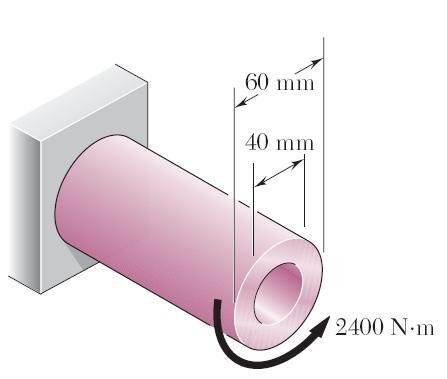
11 Example: Knowing that the internal diameter of the hollow shaft shown is d = 3 mm, determine the maximum shearing stress caused by a torque of magnitude = 1.0 knm.
12 Solution: 7 i o o max i i o o m d d 3 r m 11.5mm 3 r 0.03m, 3mm d 0.0m 0mm 0 r 0.0m, 0mm d 89.3MPa m m Nm max
13 Example:

14 7.Nm 0.0m m Nm 10 5 r r m d d m 0.03m r 0.03m, 30mm d 0.0m 0.0m r 0.0m, 0mm d 7 6 o max o max 7 i o i i o o Solution:
15 Example:
 Solution (b)")
16 6 i o o max i i o o m d d 3 r 0.0m 0.0m r 0.0m, 0mm d 0.03m 0.06m r 0.06m, 60mm d 70.6MPa m m 00Nm r 6 o max Solution: 0.08m r r Nm Nm r r 00Nm Nm r r r, r Solution (a) Solution (b)
17 Non Uniform orsion Non-uniform torsion arises when a bar made up of two or more segments of different diameters, materials or shape is subjected to torsion at several cross-sections. 117
.")
18 EXAMPLE: he solid brass rod AB (G = 39 GPa) is bonded to the solid aluminium rod BC(G = 7 GPa). Determine the angle of twist (a) at B, (b) at A.
19 SOLUION: 180Nm C c C C 180Nm 0 180Nm A B AB AB 180Nm 180Nm 0 180Nm A AB BC 180Nm B BC BC 180Nm 0 180Nm A
20 SOLUION: G L L G rad Pa (0.03) Nm G L 9 AB AB rad Pa (0.036) Nm G L 9 BC BC BC AB A
21
22
23
 the maximum shear stress in the shaft, and (b) the angle of rotation of the free end of")
24 EXAMPLE: A 0mm diameter hole is drilled 3 m deep into the steel shaft. When the two torque are applied, determine (a) the maximum shear stress in the shaft, and (b) the angle of rotation of the free end of the shaft. Use G=83GPa for steel. ( AB =9.31MPa, BC =58.77MPa) A B C
25 SOLUION: ) 10 )(83 10 ( ) 10 )(83 10 ( G L G L 9.31M Pa r 58.77M Pa r m ) 0.0 ( di do m ) ( d 3 A A BC AB A BC AB A AB AB BC BC 6 BC 6 AB 000Nm BC 000Nm 6000Nm AB
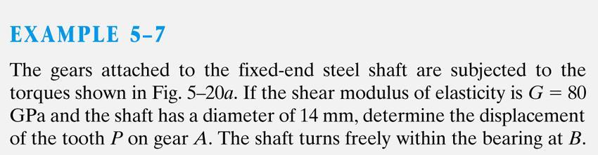
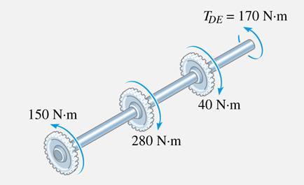
26 EXAMPLE: Four pulleys are attached to the 50mm diameter aluminium shaft. If torques are applied to the pulleys as shown in the figure, determine the angle of rotation of pulley D relative to pulley A. Use G=8GPa for aluminium. Ans:6.3, clockwise when viewed from D toward A
27 SOLUION: AB AB 600Nm 0 600Nm BC BC 900Nm 600Nm 0 300Nm CD CD 1100Nm 900Nm 600Nm 0 800Nm BC AB CD D D D D AB BC CD L L G AB G BC L G CD (800 )
28 EXAMPLE: A solid steel shaft has a diameter for m of its length and a 50mm diameter for the remaining 1m of its length, as shown in the figure. A 100 mm long pointer CD is attached to the end of the shaft. he shaft is attached to a rigid support at the left end and is subjected to a 16 knm torque at the right end of the 100 mm section and a knm torque at the right end of the 50mm section. he modulus of rigidity G of the steel is 80GPa. Determine: (a)he maximum shearing stress in the 50 mm section of the shaft. (b)he maximum shearing stress in the 100mm section of the shaft.

29 SOLUION: AB BC 61.1M Pa 3 ) ( r 16.97M Pa 3 ) ( r 1000Nm 16000Nm 000Nm 0 000Nm 16000Nm 000Nm 0 000Nm BC BC BC BC AB AB BC BC
30 EXAMPLE: Shaft BC is hollow with inner and outer diameters of 90 mm and 10 mm, respectively. Shafts AB and CD are solid of diameter d. For the loading shown, determine (a) the minimum and maximum shearing stress in shaft BC, (b) the required diameter d of shafts AB and CD if the allowable shearing stress in these shafts is 65 MPa.

31 SOLUION: Cut sections through shafts AB and BC and perform static equilibrium analysis to find torque loadings Apply elastic torsion formulas to find minimum and maximum stress on shaft BC Given allowable shearing stress and applied torque, invert the elastic torsion formula to find the required diameter 118


32 SOLUION: Cut sections through shafts AB and BC and perform static equilibrium analysis to find torque loadings M AB x 0 6kN m 6kN m CD AB 0 6kN m 1kN m BC M x 0kN m BC 119

33 Apply elastic torsion formulas to find minimum and maximum stress on shaft BC max min max min m c c BCc 86. MPa c c 1 6.7MPa 0kNm0.060m min 86.MPa mm 60mm m max min 86. MPa 6.7 MPa 10

34 Given allowable shearing stress and applied torque, invert the elastic torsion formula to find the required diameter c max c c c 3 m 65MPa d 6kNm 3 c c 77.8mm d c 77.8mm 11
 in shaft AB (b) in shaft BC (c) in")
35 EXAMPLE: Under normal operating conditions, the electric motor exerts a torque of. knm on shaft AB. Knowing that each shaft is solid, determine the maximum shearing stress (a) in shaft AB (b) in shaft BC (c) in shaft CD 1
36 Power ransmission Power transmitted by a circular shaft, P - depends upon the magnitude of the torque and the speed of rotation,. Power is the rate at which work is done. P = where, P is power (watt) is torque (Nm) is angular speed (rad/s) he angular speed is often expressed as the frequency, f, of rotation, i.e. the number of revolutions per second. his means that = f where f is measured in Hetz (Hz) = s -1 ; 13
37 Hence, P = f Also, may be expressed in revolutions per minute (rpm), denoted by N. P f N 60 (where N is in rpm) Example 5.6 How much power P(kW) may be transmitted by a solid circular shaft of diameter 80 mm turning at 0.75 Hz if the shear stress is not to exceed 0 MPa? 1
38 EXAMPLE: A 1.6-m long tubular steel shaft (G = 77 GPa) of mm outer diameter d 1 and 30 mm inner diameter d is to transmit 10 kw between a turbine and a generator. Knowing that the allowable shearing stress is 65 MPa, determine the minimum frequency at which the shaft may rotate. 15
39 SOLUION:
40 EXAMPLE: One of two hollow drive shafts of an ocean liner is 38 m long, and its outer and inner diameters are 00 mm and 00 mm respectively. he shaft is made of a steel for which all = 60 MPa and G = 77 GPa. Knowing that the maximum speed of rotation of the shaft is.75 Hz, determine (a) the maximum power that can be transmitted by the one shaft to its propeller, (b) the corresponding angle of twist of the shaft.
41 SOLUION:

42 EXAMPLE:

43 SOLUION:
44 EXAMPLE: A tubular shaft having an inner diameter of 30mm and an outer diameter of mm is to be used to transmit 90 kw of power. Determine the frequency of rotation of the shaft so that the shear stress will not exceed 50 MPa.
45 Statically Indeterminate orsional Members When all internal and reaction torques cannot be determined using only equilibrium equations Solution steps for analyzing statically indeterminate torsional members: (i) generate equilibrium equations (F, M) (ii) generate compatibility equations (constrains) (iii) generate torque-displacement relations ( = L / G) (iv) simultaneously solve all equations 16
46 Statically Indeterminate orsional Members (i) (ii) generate equilibrium equations M=0 - A - B =0 generate compatibility equations (constrains) A/B =0 (iii) generate torque-displacement relations ( = L / G) A L G AC BL G (iv) simultaneously solve all equations Here, G is assumed to be constant L=L AC +L BC BC 0 A L L BC and B L L AC
47
48
49 EXAMPLE: he design specifications of 1. m long solid circular transmission shaft require that the angle of twist of the shaft not exceed when a torque of 680 Nm is applied. Determine the required diameter of the shaft, knowing that the shaft is made of a steel with an allowable shearing stress of 83 MPa and a modulus of rigidity of 77 GPa.
50 SOLUION:
Structural Analysis I Chapter 4 - Torsion TORSION
 ORSION orsional stress results from the action of torsional or twisting moments acting about the longitudinal axis of a shaft. he effect of the application of a torsional moment, combined with appropriate
Stress Analysis Lecture 3 ME 276 Spring Dr./ Ahmed Mohamed Nagib Elmekawy
 Stress Analysis Lecture 3 ME 276 Spring 2017-2018 Dr./ Ahmed Mohamed Nagib Elmekawy Axial Stress 2 Beam under the action of two tensile forces 3 Beam under the action of two tensile forces 4 Shear Stress
[7] Torsion. [7.1] Torsion. [7.2] Statically Indeterminate Torsion. [7] Torsion Page 1 of 21
![[7] Torsion. [7.1] Torsion. [7.2] Statically Indeterminate Torsion. [7] Torsion Page 1 of 21](/thumbs/88/115835122.jpg "[7] Torsion. [7.1] Torsion. [7.2] Statically Indeterminate Torsion. [7] Torsion Page 1 of 21") [7] Torsion Page 1 of 21 [7] Torsion [7.1] Torsion [7.2] Statically Indeterminate Torsion [7] Torsion Page 2 of 21 [7.1] Torsion SHEAR STRAIN DUE TO TORSION 1) A shaft with a circular cross section is
[7] Torsion Page 1 of 21 [7] Torsion [7.1] Torsion [7.2] Statically Indeterminate Torsion [7] Torsion Page 2 of 21 [7.1] Torsion SHEAR STRAIN DUE TO TORSION 1) A shaft with a circular cross section is
The example of shafts; a) Rotating Machinery; Propeller shaft, Drive shaft b) Structural Systems; Landing gear strut, Flap drive mechanism
 Rotating Machinery; Propeller shaft, Drive shaft b) Structural Systems; Landing gear strut, Flap drive mechanism") TORSION OBJECTIVES: This chapter starts with torsion theory in the circular cross section followed by the behaviour of torsion member. The calculation of the stress stress and the angle of twist will be
TORSION OBJECTIVES: This chapter starts with torsion theory in the circular cross section followed by the behaviour of torsion member. The calculation of the stress stress and the angle of twist will be
(48) CHAPTER 3: TORSION
 CHAPTER 3: TORSION") (48) CHAPTER 3: TORSION Introduction: In this chapter structural members and machine parts that are in torsion will be considered. More specifically, you will analyze the stresses and strains in members
(48) CHAPTER 3: TORSION Introduction: In this chapter structural members and machine parts that are in torsion will be considered. More specifically, you will analyze the stresses and strains in members
CIVL222 STRENGTH OF MATERIALS. Chapter 6. Torsion
 CIVL222 STRENGTH OF MATERIALS Chapter 6 Torsion Definition Torque is a moment that tends to twist a member about its longitudinal axis. Slender members subjected to a twisting load are said to be in torsion.
MECHANICS OF MATERIALS
 2009 The McGraw-Hill Companies, Inc. All rights reserved. Fifth SI Edition CHAPTER 3 MECHANICS OF MATERIALS Ferdinand P. Beer E. Russell Johnston, Jr. John T. DeWolf David F. Mazurek Torsion Lecture Notes:
EMA 3702 Mechanics & Materials Science (Mechanics of Materials) Chapter 3 Torsion
 Chapter 3 Torsion") EMA 3702 Mechanics & Materials Science (Mechanics of Materials) Chapter 3 Torsion Introduction Stress and strain in components subjected to torque T Circular Cross-section shape Material Shaft design Non-circular
EMA 3702 Mechanics & Materials Science (Mechanics of Materials) Chapter 3 Torsion Introduction Stress and strain in components subjected to torque T Circular Cross-section shape Material Shaft design Non-circular
MECE 3321: MECHANICS OF SOLIDS CHAPTER 5
 MECE 3321: MECHANICS OF SOLIDS CHAPTER 5 SAMANTHA RAMIREZ TORSION Torque A moment that tends to twist a member about its longitudinal axis 1 TORSIONAL DEFORMATION OF A CIRCULAR SHAFT Assumption If the
Torsion Stresses in Tubes and Rods
 Torsion Stresses in Tubes and Rods This initial analysis is valid only for a restricted range of problem for which the assumptions are: Rod is initially straight. Rod twists without bending. Material is
Chapter 5: Torsion. 1. Torsional Deformation of a Circular Shaft 2. The Torsion Formula 3. Power Transmission 4. Angle of Twist CHAPTER OBJECTIVES
 CHAPTER OBJECTIVES Chapter 5: Torsion Discuss effects of applying torsional loading to a long straight member (shaft or tube) Determine stress distribution within the member under torsional load Determine
Chapter 5 Torsion STRUCTURAL MECHANICS: CE203. Notes are based on Mechanics of Materials: by R. C. Hibbeler, 7th Edition, Pearson
 STRUCTURAL MECHANICS: CE203 Chapter 5 Torsion Notes are based on Mechanics of Materials: by R. C. Hibbeler, 7th Edition, Pearson Dr B. Achour & Dr Eng. K. El-kashif Civil Engineering Department, University
Torsion of Shafts Learning objectives
 Torsion of Shafts Shafts are structural members with length significantly greater than the largest cross-sectional dimension used in transmitting torque from one plane to another. Learning objectives Understand
Chapter Objectives. Copyright 2011 Pearson Education South Asia Pte Ltd
 Chapter Objectives To determine the torsional deformation of a perfectly elastic circular shaft. To determine the support reactions when these reactions cannot be determined solely from the moment equilibrium
WORCESTER POLYTECHNIC INSTITUTE
 WORCESTER POLYTECHNIC INSTITUTE MECHANICAL ENGINEERING DEPARTMENT STRESS ANALYSIS ES-2502, C 2012 Lecture 17: 10 February 2012 General information Instructor: Cosme Furlong HL-151 (508) 831-5126 cfurlong@wpi.edu
M. Vable Mechanics of Materials: Chapter 5. Torsion of Shafts
 Torsion of Shafts Shafts are structural members with length significantly greater than the largest cross-sectional dimension used in transmitting torque from one plane to another. Learning objectives Understand
Torsion of shafts with circular symmetry
 orsion of shafts with circular symmetry Introduction Consider a uniform bar which is subject to a torque, eg through the action of two forces F separated by distance d, hence Fd orsion is the resultant
MECHANICS OF MATERIALS
 GE SI CHAPTER 3 MECHANICS OF MATERIALS Ferdinand P. Beer E. Russell Johnston, Jr. John T. DeWolf David F. Mazurek Torsion Lecture Notes: J. Walt Oler Texas Tech University Torsional Loads on Circular Shafts
PDDC 1 st Semester Civil Engineering Department Assignments of Mechanics of Solids [ ] Introduction, Fundamentals of Statics
![PDDC 1 st Semester Civil Engineering Department Assignments of Mechanics of Solids [ ] Introduction, Fundamentals of Statics](/thumbs/92/109382806.jpg "PDDC 1 st Semester Civil Engineering Department Assignments of Mechanics of Solids [ ] Introduction, Fundamentals of Statics") Page1 PDDC 1 st Semester Civil Engineering Department Assignments of Mechanics of Solids [2910601] Introduction, Fundamentals of Statics 1. Differentiate between Scalar and Vector quantity. Write S.I.
Page1 PDDC 1 st Semester Civil Engineering Department Assignments of Mechanics of Solids [2910601] Introduction, Fundamentals of Statics 1. Differentiate between Scalar and Vector quantity. Write S.I.
PROBLEM 3.3 ( )(45 10 ) T 5.17 kn m. A c c. 2 J c, (2)( ) 2 ( ) mm ( )
(45 10 ) T 5.17 kn m. A c c. 2 J c, (2)( ) 2 ( ) mm ( )") 0 mm PROEM..4 m 45 mm (a) Determine the torque that causes a maximum shearing stress of 45 MPa in the hollow cylindrical steel shaft shown. Determine the maximum shearing stress caused by the same torque
0 mm PROEM..4 m 45 mm (a) Determine the torque that causes a maximum shearing stress of 45 MPa in the hollow cylindrical steel shaft shown. Determine the maximum shearing stress caused by the same torque
Mechanical Design in Optical Engineering
 Torsion Torsion: Torsion refers to the twisting of a structural member that is loaded by couples (torque) that produce rotation about the member s longitudinal axis. In other words, the member is loaded
3.5 STRESS AND STRAIN IN PURE SHEAR. The next element is in a state of pure shear.
 3.5 STRESS AND STRAIN IN PURE SHEAR The next element is in a state of pure shear. Fig. 3-20 Stresses acting on a stress element cut from a bar in torsion (pure shear) Stresses on inclined planes Fig. 3-21
R13. II B. Tech I Semester Regular Examinations, Jan MECHANICS OF SOLIDS (Com. to ME, AME, AE, MTE) PART-A
 PART-A") SET - 1 II B. Tech I Semester Regular Examinations, Jan - 2015 MECHANICS OF SOLIDS (Com. to ME, AME, AE, MTE) Time: 3 hours Max. Marks: 70 Note: 1. Question Paper consists of two parts (Part-A and Part-B)
SET - 1 II B. Tech I Semester Regular Examinations, Jan - 2015 MECHANICS OF SOLIDS (Com. to ME, AME, AE, MTE) Time: 3 hours Max. Marks: 70 Note: 1. Question Paper consists of two parts (Part-A and Part-B)
This chapter is devoted to the study of torsion and of the stresses and deformations it causes. In the jet engine shown here, the central shaft links
 his chapter is devoted to the study of torsion and of the stresses and deformations it causes. In the jet engine shown here, the central shaft links the components of the engine to develop the thrust that
4. SHAFTS. A shaft is an element used to transmit power and torque, and it can support
 4. SHAFTS A shaft is an element used to transmit power and torque, and it can support reverse bending (fatigue). Most shafts have circular cross sections, either solid or tubular. The difference between
Sub. Code:
 Important Instructions to examiners: ) The answers should be examined by key words and not as word-to-word as given in the model answer scheme. ) The model answer and the answer written by candidate may
Mechanics of Materials II. Chapter III. A review of the fundamental formulation of stress, strain, and deflection
 Mechanics of Materials II Chapter III A review of the fundamental formulation of stress, strain, and deflection Outline Introduction Assumtions and limitations Axial loading Torsion of circular shafts
PES Institute of Technology
 PES Institute of Technology Bangalore south campus, Bangalore-5460100 Department of Mechanical Engineering Faculty name : Madhu M Date: 29/06/2012 SEM : 3 rd A SEC Subject : MECHANICS OF MATERIALS Subject
QUESTION BANK SEMESTER: III SUBJECT NAME: MECHANICS OF SOLIDS
 QUESTION BANK SEMESTER: III SUBJECT NAME: MECHANICS OF SOLIDS UNIT 1- STRESS AND STRAIN PART A (2 Marks) 1. Define longitudinal strain and lateral strain. 2. State Hooke s law. 3. Define modular ratio,
QUESTION BANK DEPARTMENT: CIVIL SEMESTER: III SUBJECT CODE: CE2201 SUBJECT NAME: MECHANICS OF SOLIDS UNIT 1- STRESS AND STRAIN PART A
 DEPARTMENT: CIVIL SUBJECT CODE: CE2201 QUESTION BANK SEMESTER: III SUBJECT NAME: MECHANICS OF SOLIDS UNIT 1- STRESS AND STRAIN PART A (2 Marks) 1. Define longitudinal strain and lateral strain. 2. State
MECHANICS OF SOLIDS TORSION - TUTORIAL 1. You should judge your progress by completing the self assessment exercises.
 MECHANICS OF SOIS TORSION - TUTORIA 1 You should judge your progress by completing the self assessment exercises. On completion of this tutorial you should be able to do the following. erive the torsion
Aluminum shell. Brass core. 40 in
 PROBLEM #1 (22 points) A solid brass core is connected to a hollow rod made of aluminum. Both are attached at each end to a rigid plate as shown in Fig. 1. The moduli of aluminum and brass are EA=11,000
Strength of Materials Prof S. K. Bhattacharya Department of Civil Engineering Indian Institute of Technology, Kharagpur Lecture - 18 Torsion - I
 Strength of Materials Prof S. K. Bhattacharya Department of Civil Engineering Indian Institute of Technology, Kharagpur Lecture - 18 Torsion - I Welcome to the first lesson of Module 4 which is on Torsion
ROTATING RING. Volume of small element = Rdθbt if weight density of ring = ρ weight of small element = ρrbtdθ. Figure 1 Rotating ring
 ROTATIONAL STRESSES INTRODUCTION High centrifugal forces are developed in machine components rotating at a high angular speed of the order of 100 to 500 revolutions per second (rps). High centrifugal force
3 Hours/100 Marks Seat No.
 *17304* 17304 14115 3 Hours/100 Marks Seat No. Instructions : (1) All questions are compulsory. (2) Illustrate your answers with neat sketches wherever necessary. (3) Figures to the right indicate full
UNIT-I STRESS, STRAIN. 1. A Member A B C D is subjected to loading as shown in fig determine the total elongation. Take E= 2 x10 5 N/mm 2
 UNIT-I STRESS, STRAIN 1. A Member A B C D is subjected to loading as shown in fig determine the total elongation. Take E= 2 x10 5 N/mm 2 Young s modulus E= 2 x10 5 N/mm 2 Area1=900mm 2 Area2=400mm 2 Area3=625mm
Chapter 4-b Axially Loaded Members
 CIVL 222 STRENGTH OF MATERIALS Chapter 4-b Axially Loaded Members AXIAL LOADED MEMBERS Today s Objectives: Students will be able to: a) Determine the elastic deformation of axially loaded member b) Apply
D : SOLID MECHANICS. Q. 1 Q. 9 carry one mark each.
 GTE 2016 Q. 1 Q. 9 carry one mark each. D : SOLID MECHNICS Q.1 single degree of freedom vibrating system has mass of 5 kg, stiffness of 500 N/m and damping coefficient of 100 N-s/m. To make the system
MECHANICS OF MATERIALS
 CHAPER MECHANICS OF MAERIALS Ferdinand P. Beer E. Russell Johnston, Jr. John. DeWolf orsion Leture Notes: J. Walt Oler exas eh University 006 he MGraw-Hill Companies, In. All rights reserved. Contents
2. Polar moment of inertia As stated above, the polar second moment of area, J is defined as. Sample copy
 GATE PATHSHALA - 91. Polar moment of inertia As stated above, the polar second moment of area, is defined as z π r dr 0 R r π R π D For a solid shaft π (6) QP 0 π d Solid shaft π d Hollow shaft, " ( do
Downloaded from Downloaded from / 1
 PURWANCHAL UNIVERSITY III SEMESTER FINAL EXAMINATION-2002 LEVEL : B. E. (Civil) SUBJECT: BEG256CI, Strength of Material Full Marks: 80 TIME: 03:00 hrs Pass marks: 32 Candidates are required to give their
MAAE 2202 A. Come to the PASS workshop with your mock exam complete. During the workshop you can work with other students to review your work.
 It is most beneficial to you to write this mock final exam UNDER EXAM CONDITIONS. This means: Complete the exam in 3 hours. Work on your own. Keep your textbook closed. Attempt every question. After the
Members Subjected to Torsional Loads
 Members Subjected to Torsional Loads Torsion of circular shafts Definition of Torsion: Consider a shaft rigidly clamped at one end and twisted at the other end by a torque T = F.d applied in a plane perpendicular
SRI CHANDRASEKHARENDRA SARASWATHI VISWA MAHAVIDHYALAYA
 SRI CHANDRASEKHARENDRA SARASWATHI VISWA MAHAVIDHYALAYA (Declared as Deemed-to-be University under Section 3 of the UGC Act, 1956, Vide notification No.F.9.9/92-U-3 dated 26 th May 1993 of the Govt. of
Module 3 : Equilibrium of rods and plates Lecture 15 : Torsion of rods. The Lecture Contains: Torsion of Rods. Torsional Energy
 The Lecture Contains: Torsion of Rods Torsional Energy This lecture is adopted from the following book 1. Theory of Elasticity, 3 rd edition by Landau and Lifshitz. Course of Theoretical Physics, vol-7
TORSION By Prof. Ahmed Amer
 ORSION By Prof. Ahmed Amer orque wisting moments or torques are fores ating through distane so as to promote rotation. Example Using a wrenh to tighten a nut in a bolt. If the bolt, wrenh and fore are
The University of Melbourne Engineering Mechanics
 The University of Melbourne 436-291 Engineering Mechanics Tutorial Four Poisson s Ratio and Axial Loading Part A (Introductory) 1. (Problem 9-22 from Hibbeler - Statics and Mechanics of Materials) A short
BE Semester- I ( ) Question Bank (MECHANICS OF SOLIDS)
 Question Bank (MECHANICS OF SOLIDS)") BE Semester- I ( ) Question Bank (MECHANICS OF SOLIDS) All questions carry equal marks(10 marks) Q.1 (a) Write the SI units of following quantities and also mention whether it is scalar or vector: (i)
BE Semester- I ( ) Question Bank (MECHANICS OF SOLIDS) All questions carry equal marks(10 marks) Q.1 (a) Write the SI units of following quantities and also mention whether it is scalar or vector: (i)
Tuesday, February 11, Chapter 3. Load and Stress Analysis. Dr. Mohammad Suliman Abuhaiba, PE
 1 Chapter 3 Load and Stress Analysis 2 Chapter Outline Equilibrium & Free-Body Diagrams Shear Force and Bending Moments in Beams Singularity Functions Stress Cartesian Stress Components Mohr s Circle for
KINGS COLLEGE OF ENGINEERING DEPARTMENT OF MECHANICAL ENGINEERING QUESTION BANK. Subject code/name: ME2254/STRENGTH OF MATERIALS Year/Sem:II / IV
 KINGS COLLEGE OF ENGINEERING DEPARTMENT OF MECHANICAL ENGINEERING QUESTION BANK Subject code/name: ME2254/STRENGTH OF MATERIALS Year/Sem:II / IV UNIT I STRESS, STRAIN DEFORMATION OF SOLIDS PART A (2 MARKS)
MARKS DISTRIBUTION AS PER CHAPTER (QUESTION ASKED IN GTU EXAM) Name Of Chapter. Applications of. Friction. Centroid & Moment.
 Name Of Chapter. Applications of. Friction. Centroid & Moment.") Introduction Fundamentals of statics Applications of fundamentals of statics Friction Centroid & Moment of inertia Simple Stresses & Strain Stresses in Beam Torsion Principle Stresses DEPARTMENT OF CIVIL
Introduction Fundamentals of statics Applications of fundamentals of statics Friction Centroid & Moment of inertia Simple Stresses & Strain Stresses in Beam Torsion Principle Stresses DEPARTMENT OF CIVIL
2. Rigid bar ABC supports a weight of W = 50 kn. Bar ABC is pinned at A and supported at B by rod (1). What is the axial force in rod (1)?
. What is the axial force in rod (1)?") IDE 110 S08 Test 1 Name: 1. Determine the internal axial forces in segments (1), (2) and (3). (a) N 1 = kn (b) N 2 = kn (c) N 3 = kn 2. Rigid bar ABC supports a weight of W = 50 kn. Bar ABC is pinned at
IDE 110 S08 Test 1 Name: 1. Determine the internal axial forces in segments (1), (2) and (3). (a) N 1 = kn (b) N 2 = kn (c) N 3 = kn 2. Rigid bar ABC supports a weight of W = 50 kn. Bar ABC is pinned at
Chapter 3. Load and Stress Analysis. Lecture Slides
 Lecture Slides Chapter 3 Load and Stress Analysis 2015 by McGraw Hill Education. This is proprietary material solely for authorized instructor use. Not authorized for sale or distribution in any manner.
EDEXCEL NATIONAL CERTIFICATE/DIPLOMA SCIENCE FOR TECHNICIANS OUTCOME 1 - STATIC AND DYNAMIC FORCES TUTORIAL 3 STRESS AND STRAIN
 EDEXCEL NATIONAL CERTIFICATE/DIPLOMA SCIENCE FOR TECHNICIANS OUTCOME 1 - STATIC AND DYNAMIC FORCES TUTORIAL 3 STRESS AND STRAIN 1 Static and dynamic forces Forces: definitions of: matter, mass, weight,
Sample Question Paper
 Scheme I Sample Question Paper Program Name : Mechanical Engineering Program Group Program Code : AE/ME/PG/PT/FG Semester : Third Course Title : Strength of Materials Marks : 70 Time: 3 Hrs. Instructions:
Stress Analysis Lecture 4 ME 276 Spring Dr./ Ahmed Mohamed Nagib Elmekawy
 Stress Analysis Lecture 4 ME 76 Spring 017-018 Dr./ Ahmed Mohamed Nagib Elmekawy Shear and Moment Diagrams Beam Sign Convention The positive directions are as follows: The internal shear force causes a
AERO 214. Lab II. Measurement of elastic moduli using bending of beams and torsion of bars
 AERO 214 Lab II. Measurement of elastic moduli using bending of beams and torsion of bars BENDING EXPERIMENT Introduction Flexural properties of materials are of interest to engineers in many different
NORMAL STRESS. The simplest form of stress is normal stress/direct stress, which is the stress perpendicular to the surface on which it acts.
 NORMAL STRESS The simplest form of stress is normal stress/direct stress, which is the stress perpendicular to the surface on which it acts. σ = force/area = P/A where σ = the normal stress P = the centric
MECE 3321 MECHANICS OF SOLIDS CHAPTER 1
 MECE 3321 MECHANICS O SOLIDS CHAPTER 1 Samantha Ramirez, MSE WHAT IS MECHANICS O MATERIALS? Rigid Bodies Statics Dynamics Mechanics Deformable Bodies Solids/Mech. Of Materials luids 1 WHAT IS MECHANICS
UNIT 1 STRESS STRAIN AND DEFORMATION OF SOLIDS, STATES OF STRESS 1. Define stress. When an external force acts on a body, it undergoes deformation.
 UNIT 1 STRESS STRAIN AND DEFORMATION OF SOLIDS, STATES OF STRESS 1. Define stress. When an external force acts on a body, it undergoes deformation. At the same time the body resists deformation. The magnitude
Samantha Ramirez, MSE. Stress. The intensity of the internal force acting on a specific plane (area) passing through a point. F 2
 passing through a point. F 2") Samantha Ramirez, MSE Stress The intensity of the internal force acting on a specific plane (area) passing through a point. Δ ΔA Δ z Δ 1 2 ΔA Δ x Δ y ΔA is an infinitesimal size area with a uniform force
Samantha Ramirez, MSE Stress The intensity of the internal force acting on a specific plane (area) passing through a point. Δ ΔA Δ z Δ 1 2 ΔA Δ x Δ y ΔA is an infinitesimal size area with a uniform force
STATICALLY INDETERMINATE STRUCTURES
 STATICALLY INDETERMINATE STRUCTURES INTRODUCTION Generally the trusses are supported on (i) a hinged support and (ii) a roller support. The reaction components of a hinged support are two (in horizontal
Torsion. Torsion is a moment that twists/deforms a member about its longitudinal axis
 Mehanis of Solids I Torsion Torsional loads on Cirular Shafts Torsion is a moment that twists/deforms a member about its longitudinal axis 1 Shearing Stresses due to Torque o Net of the internal shearing
This equation of motion may be solved either by differential equation method or by graphical method as discussed below:
 2.15. Frequency of Under Damped Forced Vibrations Consider a system consisting of spring, mass and damper as shown in Fig. 22. Let the system is acted upon by an external periodic (i.e. simple harmonic)
SN QUESTION YEAR MARK 1. State and prove the relationship between shearing stress and rate of change of bending moment at a section in a loaded beam.
 ALPHA COLLEGE OF ENGINEERING AND TECHNOLOGY DEPARTMENT OF MECHANICAL ENGINEERING MECHANICS OF SOLIDS (21000) ASSIGNMENT 1 SIMPLE STRESSES AND STRAINS SN QUESTION YEAR MARK 1 State and prove the relationship
INTRODUCTION TO STRAIN
 SIMPLE STRAIN INTRODUCTION TO STRAIN In general terms, Strain is a geometric quantity that measures the deformation of a body. There are two types of strain: normal strain: characterizes dimensional changes,
[5] Stress and Strain
![[5] Stress and Strain](/thumbs/95/123344550.jpg "[5] Stress and Strain") [5] Stress and Strain Page 1 of 34 [5] Stress and Strain [5.1] Internal Stress of Solids [5.2] Design of Simple Connections (will not be covered in class) [5.3] Deformation and Strain [5.4] Hooke s Law
[5] Stress and Strain Page 1 of 34 [5] Stress and Strain [5.1] Internal Stress of Solids [5.2] Design of Simple Connections (will not be covered in class) [5.3] Deformation and Strain [5.4] Hooke s Law
Members Subjected to Combined Loads
 Members Subjected to Combined Loads Combined Bending & Twisting : In some applications the shaft are simultaneously subjected to bending moment M and Torque T.The Bending moment comes on the shaft due
STRENGTH OF MATERIALS-I. Unit-1. Simple stresses and strains
 STRENGTH OF MATERIALS-I Unit-1 Simple stresses and strains 1. What is the Principle of surveying 2. Define Magnetic, True & Arbitrary Meridians. 3. Mention different types of chains 4. Differentiate between
Free Body Diagram: Solution: The maximum load which can be safely supported by EACH of the support members is: ANS: A =0.217 in 2
 Problem 10.9 The angle β of the system in Problem 10.8 is 60. The bars are made of a material that will safely support a tensile normal stress of 8 ksi. Based on this criterion, if you want to design the
Mechanical Engineering Ph.D. Preliminary Qualifying Examination Solid Mechanics February 25, 2002
 student personal identification (ID) number on each sheet. Do not write your name on any sheet. #1. A homogeneous, isotropic, linear elastic bar has rectangular cross sectional area A, modulus of elasticity
2. Determine the deflection at C of the beam given in fig below. Use principal of virtual work. W L/2 B A L C
 CE-1259, Strength of Materials UNIT I STRESS, STRAIN DEFORMATION OF SOLIDS Part -A 1. Define strain energy density. 2. State Maxwell s reciprocal theorem. 3. Define proof resilience. 4. State Castigliano
MECE 3321: Mechanics of Solids Chapter 6
 MECE 3321: Mechanics of Solids Chapter 6 Samantha Ramirez Beams Beams are long straight members that carry loads perpendicular to their longitudinal axis Beams are classified by the way they are supported
PERIYAR CENTENARY POLYTECHNIC COLLEGE PERIYAR NAGAR - VALLAM THANJAVUR. DEPARTMENT OF MECHANICAL ENGINEERING QUESTION BANK
 PERIYAR CENTENARY POLYTECHNIC COLLEGE PERIYAR NAGAR - VALLAM - 613 403 - THANJAVUR. DEPARTMENT OF MECHANICAL ENGINEERING QUESTION BANK Sub : Strength of Materials Year / Sem: II / III Sub Code : MEB 310
[8] Bending and Shear Loading of Beams
![[8] Bending and Shear Loading of Beams](/thumbs/92/110949676.jpg "[8] Bending and Shear Loading of Beams") [8] Bending and Shear Loading of Beams Page 1 of 28 [8] Bending and Shear Loading of Beams [8.1] Bending of Beams (will not be covered in class) [8.2] Bending Strain and Stress [8.3] Shear in Straight
[8] Bending and Shear Loading of Beams Page 1 of 28 [8] Bending and Shear Loading of Beams [8.1] Bending of Beams (will not be covered in class) [8.2] Bending Strain and Stress [8.3] Shear in Straight
MECHANICS OF MATERIALS
 Third E CHAPTER 2 Stress MECHANICS OF MATERIALS Ferdinand P. Beer E. Russell Johnston, Jr. John T. DeWolf Lecture Notes: J. Walt Oler Texas Tech University and Strain Axial Loading Contents Stress & Strain:
Solution: The strain in the bar is: ANS: E =6.37 GPa Poison s ration for the material is:
 Problem 10.4 A prismatic bar with length L 6m and a circular cross section with diameter D 0.0 m is subjected to 0-kN compressive forces at its ends. The length and diameter of the deformed bar are measured
Mechanics of Materials
 Mechanics of Materials 2. Introduction Dr. Rami Zakaria References: 1. Engineering Mechanics: Statics, R.C. Hibbeler, 12 th ed, Pearson 2. Mechanics of Materials: R.C. Hibbeler, 9 th ed, Pearson 3. Mechanics
Chapter Objectives. Copyright 2011 Pearson Education South Asia Pte Ltd
 Chapter Objectives To generalize the procedure by formulating equations that can be plotted so that they describe the internal shear and moment throughout a member. To use the relations between distributed
ME325 EXAM I (Sample)
") ME35 EXAM I (Sample) NAME: NOTE: COSED BOOK, COSED NOTES. ONY A SINGE 8.5x" ORMUA SHEET IS AOWED. ADDITIONA INORMATION IS AVAIABE ON THE AST PAGE O THIS EXAM. DO YOUR WORK ON THE EXAM ONY (NO SCRATCH PAPER
ME35 EXAM I (Sample) NAME: NOTE: COSED BOOK, COSED NOTES. ONY A SINGE 8.5x" ORMUA SHEET IS AOWED. ADDITIONA INORMATION IS AVAIABE ON THE AST PAGE O THIS EXAM. DO YOUR WORK ON THE EXAM ONY (NO SCRATCH PAPER
STRESS, STRAIN AND DEFORMATION OF SOLIDS
 VELAMMAL COLLEGE OF ENGINEERING AND TECHNOLOGY, MADURAI 625009 DEPARTMENT OF CIVIL ENGINEERING CE8301 STRENGTH OF MATERIALS I -------------------------------------------------------------------------------------------------------------------------------
Unit I Stress and Strain
 Unit I Stress and Strain Stress and strain at a point Tension, Compression, Shear Stress Hooke s Law Relationship among elastic constants Stress Strain Diagram for Mild Steel, TOR steel, Concrete Ultimate
OUTCOME 1 - TUTORIAL 3 BENDING MOMENTS. You should judge your progress by completing the self assessment exercises. CONTENTS
 Unit 2: Unit code: QCF Level: 4 Credit value: 15 Engineering Science L/601/1404 OUTCOME 1 - TUTORIAL 3 BENDING MOMENTS 1. Be able to determine the behavioural characteristics of elements of static engineering
ME Final Exam. PROBLEM NO. 4 Part A (2 points max.) M (x) y. z (neutral axis) beam cross-sec+on. 20 kip ft. 0.2 ft. 10 ft. 0.1 ft.
 M (x) y. z (neutral axis) beam cross-sec+on. 20 kip ft. 0.2 ft. 10 ft. 0.1 ft.") ME 323 - Final Exam Name December 15, 2015 Instructor (circle) PROEM NO. 4 Part A (2 points max.) Krousgrill 11:30AM-12:20PM Ghosh 2:30-3:20PM Gonzalez 12:30-1:20PM Zhao 4:30-5:20PM M (x) y 20 kip ft 0.2
ME 323 - Final Exam Name December 15, 2015 Instructor (circle) PROEM NO. 4 Part A (2 points max.) Krousgrill 11:30AM-12:20PM Ghosh 2:30-3:20PM Gonzalez 12:30-1:20PM Zhao 4:30-5:20PM M (x) y 20 kip ft 0.2
CHAPTER OBJECTIVES CHAPTER OUTLINE. 4. Axial Load
 CHAPTER OBJECTIVES Determine deformation of axially loaded members Develop a method to find support reactions when it cannot be determined from euilibrium euations Analyze the effects of thermal stress
Advanced Structural Analysis EGF Section Properties and Bending
 Advanced Structural Analysis EGF316 3. Section Properties and Bending 3.1 Loads in beams When we analyse beams, we need to consider various types of loads acting on them, for example, axial forces, shear
Chapter 3. Load and Stress Analysis
 Chapter 3 Load and Stress Analysis 2 Shear Force and Bending Moments in Beams Internal shear force V & bending moment M must ensure equilibrium Fig. 3 2 Sign Conventions for Bending and Shear Fig. 3 3
CHAPTER 4: BENDING OF BEAMS
 (74) CHAPTER 4: BENDING OF BEAMS This chapter will be devoted to the analysis of prismatic members subjected to equal and opposite couples M and M' acting in the same longitudinal plane. Such members are
Lab Exercise #3: Torsion
 Lab Exercise #3: Pre-lab assignment: Yes No Goals: 1. To evaluate the equations of angular displacement, shear stress, and shear strain for a shaft undergoing torsional stress. Principles: testing of round
March 24, Chapter 4. Deflection and Stiffness. Dr. Mohammad Suliman Abuhaiba, PE
 Chapter 4 Deflection and Stiffness 1 2 Chapter Outline Spring Rates Tension, Compression, and Torsion Deflection Due to Bending Beam Deflection Methods Beam Deflections by Superposition Strain Energy Castigliano
Mechanical Design in Optical Engineering
 OPTI Buckling Buckling and Stability: As we learned in the previous lectures, structures may fail in a variety of ways, depending on the materials, load and support conditions. We had two primary concerns:
Class XI Chapter 9 Mechanical Properties of Solids Physics
 Book Name: NCERT Solutions Question : A steel wire of length 4.7 m and cross-sectional area 5 3.0 0 m stretches by the same 5 amount as a copper wire of length 3.5 m and cross-sectional area of 4.0 0 m
Symmetric Bending of Beams
 Symmetric Bending of Beams beam is any long structural member on which loads act perpendicular to the longitudinal axis. Learning objectives Understand the theory, its limitations and its applications
Russell C. Hibbeler. Chapter 1: Stress
 Russell C. Hibbeler Chapter 1: Stress Introduction Mechanics of materials is a study of the relationship between the external loads on a body and the intensity of the internal loads within the body. This
9 MECHANICAL PROPERTIES OF SOLIDS
 9 MECHANICAL PROPERTIES OF SOLIDS Deforming force Deforming force is the force which changes the shape or size of a body. Restoring force Restoring force is the internal force developed inside the body
D : SOLID MECHANICS. Q. 1 Q. 9 carry one mark each. Q.1 Find the force (in kn) in the member BH of the truss shown.
 in the member BH of the truss shown.") D : SOLID MECHANICS Q. 1 Q. 9 carry one mark each. Q.1 Find the force (in kn) in the member BH of the truss shown. Q.2 Consider the forces of magnitude F acting on the sides of the regular hexagon having
D : SOLID MECHANICS Q. 1 Q. 9 carry one mark each. Q.1 Find the force (in kn) in the member BH of the truss shown. Q.2 Consider the forces of magnitude F acting on the sides of the regular hexagon having
twenty one concrete construction: shear & deflection ARCHITECTURAL STRUCTURES: FORM, BEHAVIOR, AND DESIGN DR. ANNE NICHOLS SUMMER 2014 lecture
 ARCHITECTURAL STRUCTURES: FORM, BEHAVIOR, AND DESIGN DR. ANNE NICHOLS SUMMER 2014 lecture twenty one concrete construction: Copyright Kirk Martini shear & deflection Concrete Shear 1 Shear in Concrete
Experiment Two (2) Torsional testing of Circular Shafts
 Torsional testing of Circular Shafts") Experiment Two (2) Torsional testing of Circular Shafts Introduction: Torsion occurs when any shaft is subjected to a torque. This is true whether the shaft is rotating (such as drive shafts on engines,
Experiment Two (2) Torsional testing of Circular Shafts Introduction: Torsion occurs when any shaft is subjected to a torque. This is true whether the shaft is rotating (such as drive shafts on engines,
INSTITUTE OF AERONAUTICAL ENGINEERING (Autonomous) Dundigal, Hyderabad
 Dundigal, Hyderabad") INSTITUTE OF AERONAUTICAL ENGINEERING (Autonomous) Dundigal, Hyderabad -00 04 CIVIL ENGINEERING QUESTION BANK Course Name : STRENGTH OF MATERIALS II Course Code : A404 Class : II B. Tech II Semester Section
INSTITUTE OF AERONAUTICAL ENGINEERING (Autonomous) Dundigal, Hyderabad -00 04 CIVIL ENGINEERING QUESTION BANK Course Name : STRENGTH OF MATERIALS II Course Code : A404 Class : II B. Tech II Semester Section
SECTION A. 8 kn/m. C 3 m 3m
 SECTION Question 1 150 m 40 kn 5 kn 8 kn/m C 3 m 3m D 50 ll dimensions in mm 15 15 Figure Q1(a) Figure Q1(b) The horizontal beam CD shown in Figure Q1(a) has a uniform cross-section as shown in Figure