Mechanical Design. Design of Shaft
|
|
|
- Curtis Collins
- 5 years ago
- Views:
Transcription
1 Mechanical Design Design of Shaft
2 Outline Practical information Shaft design
3 Definition of shaft? It is a rotating member, in general, has a circular cross-section and is used to transmit power. The shaft may be solid or hollow. It is supported on bearings and it rotates a set of gears or pulleys for the purpose p of power transmission. The shaft is generally acted upon by bending moments, torsion and axial forces.
4 Shaft versus axle and spindle Axle is a non-rotating member used for supporting rotating wheels, etc., and do not transmit any torque. Spindle is simply defined as a short shaft. However, design method remains the same for axle and spindle as that for a shaft.
5 Whatdoesitmean shaft shaft design? Material selection Geometric layout Stress and strength: static and fatigue Deflection and rigidity: bending defl., torsional twisting, slope at bearings and shaft- supported elements, and shear deflection due to transverse loading on short shafts. Vibration: critical speed
6 Material selection Many shafts are made from low carbon, colddrawn or hot-rolled steel. Alloy steel: Nickel, chromium and vanadium are some of the common alloying materials. However, alloy steel is expensive. Shafts usually don t need to be surface hardened unless they serve as the actual journal of a bearing surface. Hardening of surface (wear resistant): case hardening and carburizing ; cyaniding and nitriding.


7 Geometric layout


8 Geometric layout The geometry of shaft is generally that of stepped cylinder. There is no magic formula to give the shaft geometry for any given design situation. ti
9 Geometric layout The best approach his to learn from similar il problems that have been solved and combining the best to solve your own problem. A general layout to accommodate shaft elements, e.g. gears, bearings, and pulleys, must be specified early in the design process. Shoulders are used for axially locating shaft elements and to carry any thrust loads. Common Torque Transfer Elements: keys, set screws, pins, press or shrink fits, tapered fits.
10 Geometric layout Small pinions are often machined onto shafts. Sequence of assembly should be thought. Use chamfers to ease assembly and avoid interferences. Consider stress risers due to grooves and sharp steps in shafts. What can fail and how will it happen?
11 Shaft design based on strength Design is carried out so that stress at any location of the shaft should not exceed material yielding. Stress due to torsion: τ xy T r 16 T = = J π d 1 c ( ) 3 4 o τ τxy : Shear stress due to torsion T : Torque on the shaft Note: T 704 hp 9549 kw N ( R P M ) N ( R P M )
12 Shaft design based on strength Bending stress: σ b M y 3M = = I π d (1 c) 3 o M : Bending moment at the point of interest do : Outer diameter of the shaft c: di/do
13 Shaft design based on strength Axial stress: Fa σ a Fa 4 α Fa = = A π d (1 c ) o Fa: Axial force (tensile or compressive) α: Column-action factor(= 1.0 for tensile load) α arises due to the phenomenon of buckling of long slender members which h are acted upon by axial compressive loads. Fa
14 Shaft design based on strength Ail Axial stress (continue): α α 1 =, ( λ = L / r ) λ λ s yc =, λ > 115 π ne n = 1.0 for hinged end; n =.5 for fixed end n = 1.6 for ends partly restrained, as in bearing g, L = shaft length syc = yield stress in compression
15 Shaft design based on strength Maximum shear stress theory (ductile mat.): Failure occurs when the maximum shear stress at a point exceeds the maximum allowable shear stress for the material. Therefore, σ x τmax τ = allowable = + τ xy τ allowable ( 1+ c) 16 α Fa do = M + + π d 3 ( 1 4 ) 8 o c T
16 Shaft design based on strength Maximum normal stress theory (brittle mat.): σ x σ x σmax σ = allowable = + + τ σ allowable ( 16 α Fd 1 ) a o + c = M π d ( 1 ) 8 o c ( ) α Fa do 1+ c + M + + T 8 xy
17 Shaft design based on strength Von Mises/ Distortion-Energy theory: σ = σ = σ + 3τ max allowable x xy σ allowable ( 1+ c) 16 α Fa do = 3 ( 4 ) M T π do c
18 Shaft design based on strength τ ASME design code (ductile material): ( 16 α F 1 ) a do + c k M ( 1 c ) 8 = + + π ( ) allowable 3 4 m t π do kt where, km and kt are bending and torsion factors accounts for shock and fatigue. The values of these factors are given in ASME design code for shaft.
19 Shaft design based on strength ASME design code (brittle material): σ allowable ( 16 α F 1 ) a do + c = k mm + π d 3 ( 1 4 ) 8 o c ( ) α Fa do 1+ c + kmm + + ( kt t ) 8
20 Shaft design based on strength ASME design code: Combined shock and fatigue factors Type of load Stationary shaft Rotating shaft km kt km kt Gradualy applied load Suddenly applied load, minor shock Suddenly applied load, heavy shock
21 Shaft design based on strength ASME design code: Commercial steel shafting τallowable = 55 MPa for shaft without keyway τallowable = 40 MPa for shaft with keyway y Steel under definite specifications τallowable = 30% of the yield strength but not over 18% of the ultimate strength in tension for shafts without keyways. These values are to be reduced by 5% for the presence of keyways.
22 Standard sizes of shafts Typical sizes of solid shaft that are available in the market are: diameter increments up to 5 mm 0.5 mm 5 to 50 mm mm 50 to 100 mm.0 mm 100 to 00 mm 5.0 mm
23 Example: problem A pulley drive is transmitting power to a pinion, i which in turn is transmitting power to some other machine element. Pulley and pinion diameters are 400 mm and 00 mm respectively. Shaft has to be designed for minor to heavy shock. A C. D B m m m
24 Shaft design based on fatigue Any rotating shaft loaded by stationary bending and torsional moments will be stressed by completely reversed bending stress while the torsional stress will remain steady (i.e., Ma = M; Mm = 0; Ta = 0; Tm = T). h f bl l (f ) A design method for variable load (fatigue), like Soderberg, Goodman or Gerber criteria can be followed.
25 Shaft design based on fatigue Design under variable normal load (fatigue)
26 Shaft design based on fatigue A is the design point for which the stress amplitude is σa and the mean stress is σm. In the Soderberg criterion the mean stress material property is the yield point Sy, whereas in the the Goodman and Gerber criteria the material property is the ultimate strength Sut. For the fatigue loading, material property is the endurance limit Se in reverse bending.
27 Shaft design based on fatigue where Soderberg criterion i mod-goodman d criterion i FS σ FS σ FS σ FS σ a m a m + = 1 + = 1 Se S y Se Sut FS Gerber criterion σ FSσ S e a m + = 1 Sut σa = stress amplitude (alternating stress); Se= endurance limit (fatigue limit for completely reversed loading); σm = mean stress; Sy = yield strength; σut = ultimate tensile strength and FS= factor of safety.
28 Shaft design based on fatigue Design under variable shear load (fatigue)
29 Shaft design based on fatigue It is most common to use the Soderberg criterion. FS K S e S K σ FS σ + = 1 S Kf = fatigue stress f a m σ y + σ = S y f a y m Se FS concentration factor Sy K f σ a S e Sys K fs τ a + σm = σeq + τm = τeq S es Normal Stress Equation Shear Stress Equation
30 Shaft design based on fatigue Sy K f σ a Sys K fs τ a + σm = σeq S S e es + τ = τ m eq σeq and τeq are equivalent to allowable stresses (Sy/FS) and (Sys/FS), respectively. Effect of variable stress has been effectively defined as an equivalent static stress. C ti l f il th i b d t Conventional failure theories can be used to complete the design.
31 Shaft design based on fatigue Max. shear stress theory + Soderberg line (Westinghouse Code Formula) d σ eq τmax = τallowable = + τ eq S y S y K f σ a S y K fsτ a = + σm + + τ m FS Se Se FS K M M K T T = π Se Sy Se Sy 3 3 f a m fs a m
32 Shaft design based on rigidity Deflection is often the more demanding constraint. Many shafts are well within specification for stress but would exhibit too much deflection to be appropriate. Deflection analysis at even a single point of interest requires complete geometry information for the entire shaft.
33 Shaft design based on rigidity It is desirable to design the dimensions at critical locations to handle the stresses, and fill in reasonable estimates for all other dimensions, before performing a deflection analysis. Deflection of the shaft, both linear and angular, should be checked at gears and bearings.


34 Shaft design based on rigidity Slopes, lateral l deflection of the shaft, and/or angle of twist t of the shaft should be within some prescribed limits. Crowned tooth Diametralpitch, P = number of teeth/pitch diameter. 1 in = 5.4 mm.
35 Shaft design based on rigidity In case of sleeve bearings, shaft deflection across the bearing length should be less than the oil-film thickness. θ rad = Twist angle: ( ) T N. mm L mm ( ) ( ) ( ) ( 4 / ) G N mm J mm G: shear modulus; J: polar moment of inertia The limiting value of θ varies from 0.3 deg/m to 3 deg/m for machine tool shaft to line shaft respectively.
36 Shaft design based on rigidity Lateral ldeflection: Double integration Moment-area Energy (Castigliano Theorem) δ= f (applied load, material property, moment of inertia and given dimension of the beam). From the expression of moment of inertia, and known design parameters, including δ, shaft dimension may be obtained.
37 Double Integration Method dy M x ( ) d y M = θ () x = = dx EI dx EI () x dx y ( x) = M x ( ) EI ( x ) dx Use boundary conditions to obtain integration constants
38 Conjugate beam method Was developed by Otto Mohr in 1860 Slope (real beam) = Shear (conj. beam) Deflection (real beam) = Moment (conj. beam) Length of conj. beam = Length of real beam The load on the conjugate beam is the M/EI The load on the conjugate beam is the M/EI diagram of the loads on the actual beam
39 Conjugate beam method Real lbeam Conjugate beam Real beam Conjugate beam
40 Critical speed of rotating shaft Critical speed of a rotating shaft is the speed where it becomes dynamically y unstable. The frequency of free vibration of a non- rotating shaft is same as its critical speed. 60 wδ + w δ w δ N ( ) critical RPM = g π δ δ... n δn ( ) 1 1 n n ( w ) 1 1+ w + + w
41 Critical speed of rotating shaft W1, W. : weights of the rotating bodies (N) δ1, δ. : deflections of the respective bodies (m) For a simply supported shaft, half of its weight may be lumped at the center for better accuracy. For a cantilever shaft quarter of its weight For a cantilever shaft, quarter of its weight may be lumped at the free end.
42 Shaft design: general considerations Axial thrust loads should be taken to ground through a single thrust bearing per load direction. Do not split axial loads between thrust bearings as thermal expansion of the shaft can overload the bearings. Shaft length should be kept as short as possible, to minimize both deflections and stresses.
43 Shaft design: general considerations A cantilever beam will have a larger deflection than a simply pysupported (straddle mounted) one for the same length, load, and cross section. Hollow shafts have better stiffness/mass ratio and higher h natural frequencies than solid shafts, but will be more expensive and larger in diameter.
44 Shaft design: general considerations Slopes, lateral deflection of the shaft, and/or angle of twist of the shaft should be within some prescribed limits. First natural frequency of the shaft should be at least three times the highest forcing frequency. (A factor of ten times or more is preferred, but this is often difficult to achieve).
45 Example 3 Determine the diameter of a shaft of length L =1m, carrying a load of 5 kn at the center if the maximum allowable shaft deflection is 1mm. What is the value of the slope at the bearings. Calculate the critical speed of this shaft if a disc weighting 45 kg is placed at the center. E=09 GPa. ρst = 8740 kg/m^3.
46 Shaft design: summary Shaft design means material selection, geometric layout, stress and strength (static and fatigue), deflection and slope at bearings. Conjugate beam method for slope and deflection calculations. Some design considerations: (axial load, shaft length, support layout, hollow shafts, slopes and deflection, operating speed)
Stress Analysis Lecture 3 ME 276 Spring Dr./ Ahmed Mohamed Nagib Elmekawy
 Stress Analysis Lecture 3 ME 276 Spring 2017-2018 Dr./ Ahmed Mohamed Nagib Elmekawy Axial Stress 2 Beam under the action of two tensile forces 3 Beam under the action of two tensile forces 4 Shear Stress
MEMS Project 2 Assignment. Design of a Shaft to Transmit Torque Between Two Pulleys
 MEMS 029 Project 2 Assignment Design of a Shaft to Transmit Torque Between Two Pulleys Date: February 5, 206 Instructor: Dr. Stephen Ludwick Product Definition Shafts are incredibly important in order
Shafts Introduction. Shafts 509
 Shafts 509 C H A P T E R 14 Shafts 1. Introduction.. Material Used for Shafts.. Manufacturing of Shafts. 4. Types of Shafts. 5. Standard Sizes of Transmission Shafts. 6. Stresses in Shafts. 7. Maximum
SOLUTION (17.3) Known: A simply supported steel shaft is connected to an electric motor with a flexible coupling.
 Known: A simply supported steel shaft is connected to an electric motor with a flexible coupling.") SOLUTION (17.3) Known: A simply supported steel shaft is connected to an electric motor with a flexible coupling. Find: Determine the value of the critical speed of rotation for the shaft. Schematic and
SOLUTION (17.3) Known: A simply supported steel shaft is connected to an electric motor with a flexible coupling. Find: Determine the value of the critical speed of rotation for the shaft. Schematic and
Chapter 8 Structural Design and Analysis. Strength and stiffness 5 types of load: Tension Compression Shear Bending Torsion
 Chapter 8 Structural Design and Analysis 1 Strength and stiffness 5 types of load: Tension Compression Shear Bending Torsion Normal Stress Stress is a state when a material is loaded. For normal forces
CHAPTER 2 Failure/Fracture Criterion
 (11) CHAPTER 2 Failure/Fracture Criterion (12) Failure (Yield) Criteria for Ductile Materials under Plane Stress Designer engineer: 1- Analysis of loading (for simple geometry using what you learn here
PES Institute of Technology
 PES Institute of Technology Bangalore south campus, Bangalore-5460100 Department of Mechanical Engineering Faculty name : Madhu M Date: 29/06/2012 SEM : 3 rd A SEC Subject : MECHANICS OF MATERIALS Subject
DESIGN FOR FATIGUE STRENGTH
 UNIT 3 DESIGN FOR FATIGUE STRENGTH Instructional Objectives Mean and variable stresses and endurance limit. S-N plots for metals and non-metals and relation between endurance limit and ultimate tensile
Static Failure (pg 206)
") Static Failure (pg 06) All material followed Hookeʹs law which states that strain is proportional to stress applied, until it exceed the proportional limits. It will reach and exceed the elastic limit
Static Failure (pg 06) All material followed Hookeʹs law which states that strain is proportional to stress applied, until it exceed the proportional limits. It will reach and exceed the elastic limit
4. SHAFTS. A shaft is an element used to transmit power and torque, and it can support
 4. SHAFTS A shaft is an element used to transmit power and torque, and it can support reverse bending (fatigue). Most shafts have circular cross sections, either solid or tubular. The difference between
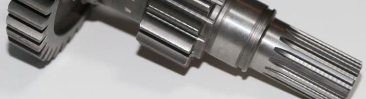
Automobile manual transmission
 Design of Shaft A shaft is a rotating member usually of circular crosssection (soli or hollow), which is use to transmit power an rotational motion. Axles are non rotating member. Elements such as gears,
2. Polar moment of inertia As stated above, the polar second moment of area, J is defined as. Sample copy
 GATE PATHSHALA - 91. Polar moment of inertia As stated above, the polar second moment of area, is defined as z π r dr 0 R r π R π D For a solid shaft π (6) QP 0 π d Solid shaft π d Hollow shaft, " ( do
Tuesday, February 11, Chapter 3. Load and Stress Analysis. Dr. Mohammad Suliman Abuhaiba, PE
 1 Chapter 3 Load and Stress Analysis 2 Chapter Outline Equilibrium & Free-Body Diagrams Shear Force and Bending Moments in Beams Singularity Functions Stress Cartesian Stress Components Mohr s Circle for
MECHANICS OF MATERIALS
 2009 The McGraw-Hill Companies, Inc. All rights reserved. Fifth SI Edition CHAPTER 3 MECHANICS OF MATERIALS Ferdinand P. Beer E. Russell Johnston, Jr. John T. DeWolf David F. Mazurek Torsion Lecture Notes:
Springs Lecture 3. Extension Springs
 Springs Lecture 3 Extension Springs Carry tensile loading Extension springs Max. Normal stress at A due to Bending and Axial loading σ A K A 6D 4 F K A + 3 πd πd 4C 4C C ( C ) r d C Max. torsional stress
D : SOLID MECHANICS. Q. 1 Q. 9 carry one mark each.
 GTE 2016 Q. 1 Q. 9 carry one mark each. D : SOLID MECHNICS Q.1 single degree of freedom vibrating system has mass of 5 kg, stiffness of 500 N/m and damping coefficient of 100 N-s/m. To make the system
Design against fluctuating load
 Design against fluctuating load In many applications, the force acting on the spring is not constants but varies in magnitude with time. The valve springs of automotive engine subjected to millions of
Shafts. Fig.(4.1) Dr. Salah Gasim Ahmed YIC 1
 Dr. Salah Gasim Ahmed YIC 1") Shafts. Power transmission shafting Continuous mechanical power is usually transmitted along and etween rotating shafts. The transfer etween shafts is accomplished y gears, elts, chains or other similar
Shafts. Power transmission shafting Continuous mechanical power is usually transmitted along and etween rotating shafts. The transfer etween shafts is accomplished y gears, elts, chains or other similar
ME Final Exam. PROBLEM NO. 4 Part A (2 points max.) M (x) y. z (neutral axis) beam cross-sec+on. 20 kip ft. 0.2 ft. 10 ft. 0.1 ft.
 M (x) y. z (neutral axis) beam cross-sec+on. 20 kip ft. 0.2 ft. 10 ft. 0.1 ft.") ME 323 - Final Exam Name December 15, 2015 Instructor (circle) PROEM NO. 4 Part A (2 points max.) Krousgrill 11:30AM-12:20PM Ghosh 2:30-3:20PM Gonzalez 12:30-1:20PM Zhao 4:30-5:20PM M (x) y 20 kip ft 0.2
ME 323 - Final Exam Name December 15, 2015 Instructor (circle) PROEM NO. 4 Part A (2 points max.) Krousgrill 11:30AM-12:20PM Ghosh 2:30-3:20PM Gonzalez 12:30-1:20PM Zhao 4:30-5:20PM M (x) y 20 kip ft 0.2
Note: Read section (12-1) objective of this chapter (Page 532)
 objective of this chapter (Page 532)") References: Machine Elements in Mechanical Design by Robert L. Mott, P.E. (Chapter 12 Note: Read section (12-1 objective of this chapter (Page 532 Page 1 of 29 Shaft Design Procedure (Sec. 12-2, Page 532
References: Machine Elements in Mechanical Design by Robert L. Mott, P.E. (Chapter 12 Note: Read section (12-1 objective of this chapter (Page 532 Page 1 of 29 Shaft Design Procedure (Sec. 12-2, Page 532
EMA 3702 Mechanics & Materials Science (Mechanics of Materials) Chapter 3 Torsion
 Chapter 3 Torsion") EMA 3702 Mechanics & Materials Science (Mechanics of Materials) Chapter 3 Torsion Introduction Stress and strain in components subjected to torque T Circular Cross-section shape Material Shaft design Non-circular
EMA 3702 Mechanics & Materials Science (Mechanics of Materials) Chapter 3 Torsion Introduction Stress and strain in components subjected to torque T Circular Cross-section shape Material Shaft design Non-circular
Chapter 5: Torsion. 1. Torsional Deformation of a Circular Shaft 2. The Torsion Formula 3. Power Transmission 4. Angle of Twist CHAPTER OBJECTIVES
 CHAPTER OBJECTIVES Chapter 5: Torsion Discuss effects of applying torsional loading to a long straight member (shaft or tube) Determine stress distribution within the member under torsional load Determine
Mechanics of Materials II. Chapter III. A review of the fundamental formulation of stress, strain, and deflection
 Mechanics of Materials II Chapter III A review of the fundamental formulation of stress, strain, and deflection Outline Introduction Assumtions and limitations Axial loading Torsion of circular shafts
MAAE 2202 A. Come to the PASS workshop with your mock exam complete. During the workshop you can work with other students to review your work.
 It is most beneficial to you to write this mock final exam UNDER EXAM CONDITIONS. This means: Complete the exam in 3 hours. Work on your own. Keep your textbook closed. Attempt every question. After the
CHAPTER 8 SCREWS, FASTENERS, NONPERMANENT JOINTS
 CHAPTER 8 SCREWS, FASTENERS, NONPERMANENT JOINTS This chapter deals with the design and analysis of nonpermanent fasteners such as bolts, power screws, cap screws, setscrews, eys and pins. 8- Standards
2. Rigid bar ABC supports a weight of W = 50 kn. Bar ABC is pinned at A and supported at B by rod (1). What is the axial force in rod (1)?
. What is the axial force in rod (1)?") IDE 110 S08 Test 1 Name: 1. Determine the internal axial forces in segments (1), (2) and (3). (a) N 1 = kn (b) N 2 = kn (c) N 3 = kn 2. Rigid bar ABC supports a weight of W = 50 kn. Bar ABC is pinned at
IDE 110 S08 Test 1 Name: 1. Determine the internal axial forces in segments (1), (2) and (3). (a) N 1 = kn (b) N 2 = kn (c) N 3 = kn 2. Rigid bar ABC supports a weight of W = 50 kn. Bar ABC is pinned at
FME461 Engineering Design II
 FME461 Engineering Design II Dr.Hussein Jama Hussein.jama@uobi.ac.ke Office 414 Lecture: Mon 8am -10am Tutorial Tue 3pm - 5pm 10/1/2013 1 Semester outline Date Week Topics Reference Reading 9 th Sept 1
March 24, Chapter 4. Deflection and Stiffness. Dr. Mohammad Suliman Abuhaiba, PE
 Chapter 4 Deflection and Stiffness 1 2 Chapter Outline Spring Rates Tension, Compression, and Torsion Deflection Due to Bending Beam Deflection Methods Beam Deflections by Superposition Strain Energy Castigliano
Sample Questions for the ME328 Machine Design Final Examination Closed notes, closed book, no calculator.
 Sample Questions for the ME328 Machine Design Final Examination Closed notes, closed book, no calculator. The following is from the first page of the examination. I recommend you read it before the exam.
QUESTION BANK SEMESTER: III SUBJECT NAME: MECHANICS OF SOLIDS
 QUESTION BANK SEMESTER: III SUBJECT NAME: MECHANICS OF SOLIDS UNIT 1- STRESS AND STRAIN PART A (2 Marks) 1. Define longitudinal strain and lateral strain. 2. State Hooke s law. 3. Define modular ratio,
3.5 STRESS AND STRAIN IN PURE SHEAR. The next element is in a state of pure shear.
 3.5 STRESS AND STRAIN IN PURE SHEAR The next element is in a state of pure shear. Fig. 3-20 Stresses acting on a stress element cut from a bar in torsion (pure shear) Stresses on inclined planes Fig. 3-21
Review Lecture. AE1108-II: Aerospace Mechanics of Materials. Dr. Calvin Rans Dr. Sofia Teixeira De Freitas
 Review Lecture AE1108-II: Aerospace Mechanics of Materials Dr. Calvin Rans Dr. Sofia Teixeira De Freitas Aerospace Structures & Materials Faculty of Aerospace Engineering Analysis of an Engineering System
Failure from static loading
 Failure from static loading Topics Quiz /1/07 Failures from static loading Reading Chapter 5 Homework HW 3 due /1 HW 4 due /8 What is Failure? Failure any change in a machine part which makes it unable
Chapter 3. Load and Stress Analysis. Lecture Slides
 Lecture Slides Chapter 3 Load and Stress Analysis 2015 by McGraw Hill Education. This is proprietary material solely for authorized instructor use. Not authorized for sale or distribution in any manner.
D : SOLID MECHANICS. Q. 1 Q. 9 carry one mark each. Q.1 Find the force (in kn) in the member BH of the truss shown.
 in the member BH of the truss shown.") D : SOLID MECHANICS Q. 1 Q. 9 carry one mark each. Q.1 Find the force (in kn) in the member BH of the truss shown. Q.2 Consider the forces of magnitude F acting on the sides of the regular hexagon having
D : SOLID MECHANICS Q. 1 Q. 9 carry one mark each. Q.1 Find the force (in kn) in the member BH of the truss shown. Q.2 Consider the forces of magnitude F acting on the sides of the regular hexagon having
12/25/ :27 PM. Chapter 14. Spur and Helical Gears. Mohammad Suliman Abuhaiba, Ph.D., PE
 Chapter 14 Spur and Helical Gears 1 2 The Lewis Bending Equation Equation to estimate bending stress in gear teeth in which tooth form entered into the formulation: 3 The Lewis Bending Equation Assume
Experiment Two (2) Torsional testing of Circular Shafts
 Torsional testing of Circular Shafts") Experiment Two (2) Torsional testing of Circular Shafts Introduction: Torsion occurs when any shaft is subjected to a torque. This is true whether the shaft is rotating (such as drive shafts on engines,
Experiment Two (2) Torsional testing of Circular Shafts Introduction: Torsion occurs when any shaft is subjected to a torque. This is true whether the shaft is rotating (such as drive shafts on engines,
2. Determine the deflection at C of the beam given in fig below. Use principal of virtual work. W L/2 B A L C
 CE-1259, Strength of Materials UNIT I STRESS, STRAIN DEFORMATION OF SOLIDS Part -A 1. Define strain energy density. 2. State Maxwell s reciprocal theorem. 3. Define proof resilience. 4. State Castigliano
R13. II B. Tech I Semester Regular Examinations, Jan MECHANICS OF SOLIDS (Com. to ME, AME, AE, MTE) PART-A
 PART-A") SET - 1 II B. Tech I Semester Regular Examinations, Jan - 2015 MECHANICS OF SOLIDS (Com. to ME, AME, AE, MTE) Time: 3 hours Max. Marks: 70 Note: 1. Question Paper consists of two parts (Part-A and Part-B)
SET - 1 II B. Tech I Semester Regular Examinations, Jan - 2015 MECHANICS OF SOLIDS (Com. to ME, AME, AE, MTE) Time: 3 hours Max. Marks: 70 Note: 1. Question Paper consists of two parts (Part-A and Part-B)
Design of Beams (Unit - 8)
") Design of Beams (Unit - 8) Contents Introduction Beam types Lateral stability of beams Factors affecting lateral stability Behaviour of simple and built - up beams in bending (Without vertical stiffeners)
Design of Beams (Unit - 8) Contents Introduction Beam types Lateral stability of beams Factors affecting lateral stability Behaviour of simple and built - up beams in bending (Without vertical stiffeners)
Design and analysis of axle under fatigue life loading condition
 Design and analysis of axle under fatigue life loading condition Research Paper Mehul Pravinchandra Mehta 1 Assistant Professor, 1 Vadodara Institute of Engineering, kotambi, Vadodara, Gujarat, India Mechanical
Torsion Stresses in Tubes and Rods
 Torsion Stresses in Tubes and Rods This initial analysis is valid only for a restricted range of problem for which the assumptions are: Rod is initially straight. Rod twists without bending. Material is
Members Subjected to Torsional Loads
 Members Subjected to Torsional Loads Torsion of circular shafts Definition of Torsion: Consider a shaft rigidly clamped at one end and twisted at the other end by a torque T = F.d applied in a plane perpendicular
Use Hooke s Law (as it applies in the uniaxial direction),
,") 0.6 STRSS-STRAIN RLATIONSHIP Use the principle of superposition Use Poisson s ratio, v lateral longitudinal Use Hooke s Law (as it applies in the uniaxial direction), x x v y z, y y vx z, z z vx y Copyright
0.6 STRSS-STRAIN RLATIONSHIP Use the principle of superposition Use Poisson s ratio, v lateral longitudinal Use Hooke s Law (as it applies in the uniaxial direction), x x v y z, y y vx z, z z vx y Copyright
COURSE TITLE : APPLIED MECHANICS & STRENGTH OF MATERIALS COURSE CODE : 4017 COURSE CATEGORY : A PERIODS/WEEK : 6 PERIODS/ SEMESTER : 108 CREDITS : 5
 COURSE TITLE : APPLIED MECHANICS & STRENGTH OF MATERIALS COURSE CODE : 4017 COURSE CATEGORY : A PERIODS/WEEK : 6 PERIODS/ SEMESTER : 108 CREDITS : 5 TIME SCHEDULE MODULE TOPICS PERIODS 1 Simple stresses
SSC-JE MAINS ONLINE TEST SERIES / CIVIL ENGINEERING SOM + TOS
 SSC-JE MAINS ONLINE TEST SERIES / CIVIL ENGINEERING SOM + TOS Time Allowed:2 Hours Maximum Marks: 300 Attention: 1. Paper consists of Part A (Civil & Structural) Part B (Electrical) and Part C (Mechanical)
QUESTION BANK DEPARTMENT: CIVIL SEMESTER: III SUBJECT CODE: CE2201 SUBJECT NAME: MECHANICS OF SOLIDS UNIT 1- STRESS AND STRAIN PART A
 DEPARTMENT: CIVIL SUBJECT CODE: CE2201 QUESTION BANK SEMESTER: III SUBJECT NAME: MECHANICS OF SOLIDS UNIT 1- STRESS AND STRAIN PART A (2 Marks) 1. Define longitudinal strain and lateral strain. 2. State
Downloaded from Downloaded from / 1
 PURWANCHAL UNIVERSITY III SEMESTER FINAL EXAMINATION-2002 LEVEL : B. E. (Civil) SUBJECT: BEG256CI, Strength of Material Full Marks: 80 TIME: 03:00 hrs Pass marks: 32 Candidates are required to give their
MECHANICAL ENGINEERING» COURSE:
 PROGRAMME: «BSc in MECHANICAL ENGINEERING» COURSE: Machine Elements I - AMEM 316 ACADEMIC YEAR: 20013-14 INSTRUCTOR: Dr. Antonios Lontos DATE: 06/12/2013 Assignment 1: «SHAFT DESIGN» Prepared by: Aaaa
MECHANICS OF MATERIALS Design of a Transmission Shaft
 Design of a Transmission Shaft If power is transferred to and from the shaft by gears or sprocket wheels, the shaft is subjected to transverse loading as well as shear loading. Normal stresses due to transverse
SRI CHANDRASEKHARENDRA SARASWATHI VISWA MAHAVIDHYALAYA
 SRI CHANDRASEKHARENDRA SARASWATHI VISWA MAHAVIDHYALAYA (Declared as Deemed-to-be University under Section 3 of the UGC Act, 1956, Vide notification No.F.9.9/92-U-3 dated 26 th May 1993 of the Govt. of
NAME: Given Formulae: Law of Cosines: Law of Sines:
 NME: Given Formulae: Law of Cosines: EXM 3 PST PROBLEMS (LESSONS 21 TO 28) 100 points Thursday, November 16, 2017, 7pm to 9:30, Room 200 You are allowed to use a calculator and drawing equipment, only.
KINGS COLLEGE OF ENGINEERING DEPARTMENT OF MECHANICAL ENGINEERING QUESTION BANK. Subject code/name: ME2254/STRENGTH OF MATERIALS Year/Sem:II / IV
 KINGS COLLEGE OF ENGINEERING DEPARTMENT OF MECHANICAL ENGINEERING QUESTION BANK Subject code/name: ME2254/STRENGTH OF MATERIALS Year/Sem:II / IV UNIT I STRESS, STRAIN DEFORMATION OF SOLIDS PART A (2 MARKS)
(48) CHAPTER 3: TORSION
 CHAPTER 3: TORSION") (48) CHAPTER 3: TORSION Introduction: In this chapter structural members and machine parts that are in torsion will be considered. More specifically, you will analyze the stresses and strains in members
(48) CHAPTER 3: TORSION Introduction: In this chapter structural members and machine parts that are in torsion will be considered. More specifically, you will analyze the stresses and strains in members
Structural Analysis I Chapter 4 - Torsion TORSION
 ORSION orsional stress results from the action of torsional or twisting moments acting about the longitudinal axis of a shaft. he effect of the application of a torsional moment, combined with appropriate
High Tech High Top Hat Technicians. An Introduction to Solid Mechanics. Is that supposed to bend there?
 High Tech High Top Hat Technicians An Introduction to Solid Mechanics Or Is that supposed to bend there? Why don't we fall through the floor? The power of any Spring is in the same proportion with the
PERIYAR CENTENARY POLYTECHNIC COLLEGE PERIYAR NAGAR - VALLAM THANJAVUR. DEPARTMENT OF MECHANICAL ENGINEERING QUESTION BANK
 PERIYAR CENTENARY POLYTECHNIC COLLEGE PERIYAR NAGAR - VALLAM - 613 403 - THANJAVUR. DEPARTMENT OF MECHANICAL ENGINEERING QUESTION BANK Sub : Strength of Materials Year / Sem: II / III Sub Code : MEB 310
Arberi Ferraj. Wentworth Institute of Technology. Design of Machine Elements MECH 420
 P a g e 1 Arberi Ferraj Wentworth Institute of Technology Design of Machine Elements MECH 420 P a g e 2 1. Executive Summary A scissor car jack was designed and must be reverse-engineered in order to discover
CIVL222 STRENGTH OF MATERIALS. Chapter 6. Torsion
 CIVL222 STRENGTH OF MATERIALS Chapter 6 Torsion Definition Torque is a moment that tends to twist a member about its longitudinal axis. Slender members subjected to a twisting load are said to be in torsion.
CE6306 STRENGTH OF MATERIALS TWO MARK QUESTIONS WITH ANSWERS ACADEMIC YEAR
 CE6306 STRENGTH OF MATERIALS TWO MARK QUESTIONS WITH ANSWERS ACADEMIC YEAR 2014-2015 UNIT - 1 STRESS, STRAIN AND DEFORMATION OF SOLIDS PART- A 1. Define tensile stress and tensile strain. The stress induced
PDDC 1 st Semester Civil Engineering Department Assignments of Mechanics of Solids [ ] Introduction, Fundamentals of Statics
![PDDC 1 st Semester Civil Engineering Department Assignments of Mechanics of Solids [ ] Introduction, Fundamentals of Statics](/thumbs/92/109382806.jpg "PDDC 1 st Semester Civil Engineering Department Assignments of Mechanics of Solids [ ] Introduction, Fundamentals of Statics") Page1 PDDC 1 st Semester Civil Engineering Department Assignments of Mechanics of Solids [2910601] Introduction, Fundamentals of Statics 1. Differentiate between Scalar and Vector quantity. Write S.I.
Page1 PDDC 1 st Semester Civil Engineering Department Assignments of Mechanics of Solids [2910601] Introduction, Fundamentals of Statics 1. Differentiate between Scalar and Vector quantity. Write S.I.
Sub. Code:
 Important Instructions to examiners: ) The answers should be examined by key words and not as word-to-word as given in the model answer scheme. ) The model answer and the answer written by candidate may
Aluminum shell. Brass core. 40 in
 PROBLEM #1 (22 points) A solid brass core is connected to a hollow rod made of aluminum. Both are attached at each end to a rigid plate as shown in Fig. 1. The moduli of aluminum and brass are EA=11,000
: APPLIED MECHANICS & STRENGTH OF MATERIALS COURSE CODE : 4021 COURSE CATEGORY : A PERIODS/ WEEK : 5 PERIODS/ SEMESTER : 75 CREDIT : 5 TIME SCHEDULE
 COURSE TITLE : APPLIED MECHANICS & STRENGTH OF MATERIALS COURSE CODE : 4021 COURSE CATEGORY : A PERIODS/ WEEK : 5 PERIODS/ SEMESTER : 75 CREDIT : 5 TIME SCHEDULE MODULE TOPIC PERIODS 1 Simple stresses
Helical Gears n A Textbook of Machine Design
 1066 n A Textbook of Machine Design C H A P T E R 9 Helical Gears 1. Introduction.. Terms used in Helical Gears. 3. Face Width of Helical Gears. 4. Formative or Equivalent Number of Teeth for Helical Gears.
Torsion of shafts with circular symmetry
 orsion of shafts with circular symmetry Introduction Consider a uniform bar which is subject to a torque, eg through the action of two forces F separated by distance d, hence Fd orsion is the resultant
Chapter 5 Elastic Strain, Deflection, and Stability 1. Elastic Stress-Strain Relationship
 Chapter 5 Elastic Strain, Deflection, and Stability Elastic Stress-Strain Relationship A stress in the x-direction causes a strain in the x-direction by σ x also causes a strain in the y-direction & z-direction
Mechanics of Materials Primer
 Mechanics of Materials rimer Notation: A = area (net = with holes, bearing = in contact, etc...) b = total width of material at a horizontal section d = diameter of a hole D = symbol for diameter E = modulus
2.1 Background of Piping Stresses
 2 Research Review One of the major additions to Tmin was the inclusion of analysis of a 2-Dimensional vertical piping span. The original plan from Dupont was to include several types of 2-D and 3-D vertical
Chapter 4 Deflection and Stiffness
 Chapter 4 Deflection and Stiffness Asst. Prof. Dr. Supakit Rooppakhun Chapter Outline Deflection and Stiffness 4-1 Spring Rates 4-2 Tension, Compression, and Torsion 4-3 Deflection Due to Bending 4-4 Beam
University of Pretoria Department of Mechanical & Aeronautical Engineering MOW 227, 2 nd Semester 2014
 Universit of Pretoria Department of Mechanical & Aeronautical Engineering MOW 7, nd Semester 04 Semester Test Date: August, 04 Total: 00 Internal eaminer: Duration: hours Mr. Riaan Meeser Instructions:
Lecture Slides. Chapter 4. Deflection and Stiffness. The McGraw-Hill Companies 2012
 Lecture Slides Chapter 4 Deflection and Stiffness The McGraw-Hill Companies 2012 Chapter Outline Force vs Deflection Elasticity property of a material that enables it to regain its original configuration
Mechanics of Materials MENG 270 Fall 2003 Exam 3 Time allowed: 90min. Q.1(a) Q.1 (b) Q.2 Q.3 Q.4 Total
 Q.1 (b) Q.2 Q.3 Q.4 Total") Mechanics of Materials MENG 70 Fall 00 Eam Time allowed: 90min Name. Computer No. Q.(a) Q. (b) Q. Q. Q.4 Total Problem No. (a) [5Points] An air vessel is 500 mm average diameter and 0 mm thickness, the
Mechanics of Materials MENG 70 Fall 00 Eam Time allowed: 90min Name. Computer No. Q.(a) Q. (b) Q. Q. Q.4 Total Problem No. (a) [5Points] An air vessel is 500 mm average diameter and 0 mm thickness, the
Module 5: Theories of Failure
 Module 5: Theories of Failure Objectives: The objectives/outcomes of this lecture on Theories of Failure is to enable students for 1. Recognize loading on Structural Members/Machine elements and allowable
5. Repeated Loading. 330:148 (g) Machine Design. Dynamic Strength. Dynamic Loads. Dynamic Strength. Dynamic Strength. Nageswara Rao Posinasetti
 Machine Design. Dynamic Strength. Dynamic Loads. Dynamic Strength. Dynamic Strength. Nageswara Rao Posinasetti") 330:48 (g) achine Design Nageswara Rao Posinasetti P N Rao 5. Repeated Loading Objectives Identify the various kinds of loading encountered on a part and learn to combine them as appropriate. Determine
330:48 (g) achine Design Nageswara Rao Posinasetti P N Rao 5. Repeated Loading Objectives Identify the various kinds of loading encountered on a part and learn to combine them as appropriate. Determine
Mechanical Principles
 Unit 8: Unit code Mechanical Principles F/615/1482 Unit level 4 Credit value 15 Introduction Mechanical principles have been crucial for engineers to convert the energy produced by burning oil and gas
FINAL EXAMINATION. (CE130-2 Mechanics of Materials)
") UNIVERSITY OF CLIFORNI, ERKELEY FLL SEMESTER 001 FINL EXMINTION (CE130- Mechanics of Materials) Problem 1: (15 points) pinned -bar structure is shown in Figure 1. There is an external force, W = 5000N,
UNIVERSITY OF CLIFORNI, ERKELEY FLL SEMESTER 001 FINL EXMINTION (CE130- Mechanics of Materials) Problem 1: (15 points) pinned -bar structure is shown in Figure 1. There is an external force, W = 5000N,
Chapter 5 Torsion STRUCTURAL MECHANICS: CE203. Notes are based on Mechanics of Materials: by R. C. Hibbeler, 7th Edition, Pearson
 STRUCTURAL MECHANICS: CE203 Chapter 5 Torsion Notes are based on Mechanics of Materials: by R. C. Hibbeler, 7th Edition, Pearson Dr B. Achour & Dr Eng. K. El-kashif Civil Engineering Department, University
1 of 12. Given: Law of Cosines: C. Law of Sines: Stress = E = G
 ES230 STRENGTH OF MATERIALS FINAL EXAM: WEDNESDAY, MAY 15 TH, 4PM TO 7PM, AEC200 Closed book. Calculator and writing supplies allowed. Protractor and compass required. 180 Minute Time Limit You must have
MAE 322 Machine Design. Dr. Hodge Jenkins Mercer University
 MAE 322 Machine Design Dr. Hodge Jenkins Mercer University What is this Machine Design course really about? What you will learn: How to design machine elements 1) Design so they won t break under varying
Lecture Slides. Chapter 14. Spur and Helical Gears
 Lecture Slides Chapter 14 Spur and Helical Gears The McGraw-Hill Companies 2012 Chapter Outline Cantilever Beam Model of Bending Stress in Gear Tooth Fig. 14 1 Lewis Equation Lewis Equation Lewis Form
SECOND ENGINEER REG. III/2 APPLIED MECHANICS
 SECOND ENGINEER REG. III/2 APPLIED MECHANICS LIST OF TOPICS Static s Friction Kinematics Dynamics Machines Strength of Materials Hydrostatics Hydrodynamics A STATICS 1 Solves problems involving forces
DEPARTMENT OF CIVIL ENGINEERING
 KINGS COLLEGE OF ENGINEERING DEPARTMENT OF CIVIL ENGINEERING SUBJECT: CE 2252 STRENGTH OF MATERIALS UNIT: I ENERGY METHODS 1. Define: Strain Energy When an elastic body is under the action of external
The problem of transmitting a torque or rotary motion from one plane to another is frequently encountered in machine design.
 CHAPER ORSION ORSION orsion refers to the twisting of a structural member when it is loaded by moments/torques that produce rotation about the longitudinal axis of the member he problem of transmitting
Module 2 Stresses in machine elements. Version 2 ME, IIT Kharagpur
 Module Stresses in machine elements Lesson Compound stresses in machine parts Instructional Objectives t the end of this lesson, the student should be able to understand Elements of force system at a beam
Name :. Roll No. :... Invigilator s Signature :.. CS/B.TECH (CE-NEW)/SEM-3/CE-301/ SOLID MECHANICS
/SEM-3/CE-301/ SOLID MECHANICS") Name :. Roll No. :..... Invigilator s Signature :.. 2011 SOLID MECHANICS Time Allotted : 3 Hours Full Marks : 70 The figures in the margin indicate full marks. Candidates are required to give their answers
Name :. Roll No. :..... Invigilator s Signature :.. 2011 SOLID MECHANICS Time Allotted : 3 Hours Full Marks : 70 The figures in the margin indicate full marks. Candidates are required to give their answers
Donald P. Shiley School of Engineering ME 328 Machine Design, Spring 2019 Assignment 1 Review Questions
 Donald P. Shiley School of Engineering ME 328 Machine Design, Spring 2019 Assignment 1 Review Questions Name: This is assignment is in workbook format, meaning you may fill in the blanks (you do not need
Critical Load columns buckling critical load
 Buckling of Columns Buckling of Columns Critical Load Some member may be subjected to compressive loadings, and if these members are long enough to cause the member to deflect laterally or sideway. To
Matlab Sheet 2. Arrays
 Matlab Sheet 2 Arrays 1. a. Create the vector x having 50 logarithmically spaced values starting at 10 and ending at 1000. b. Create the vector x having 20 logarithmically spaced values starting at 10
UNIT-I STRESS, STRAIN. 1. A Member A B C D is subjected to loading as shown in fig determine the total elongation. Take E= 2 x10 5 N/mm 2
 UNIT-I STRESS, STRAIN 1. A Member A B C D is subjected to loading as shown in fig determine the total elongation. Take E= 2 x10 5 N/mm 2 Young s modulus E= 2 x10 5 N/mm 2 Area1=900mm 2 Area2=400mm 2 Area3=625mm
MECH 401 Mechanical Design Applications
 MECH 401 Mechanical Design Applications Dr. M. O Malley Master Notes Spring 008 Dr. D. M. McStravick Rice University Updates HW 1 due Thursday (1-17-08) Last time Introduction Units Reliability engineering
DESIGN & STATIC STRUCTURAL ANALYSIS OF CRANKSHAFT FOR HIGH PRESSURE PLUNGER PUMP
 DESIGN & STATIC STRUCTURAL ANALYSIS OF CRANKSHAFT FOR HIGH PRESSURE PLUNGER PUMP Kiran A. Raut 1 and Sachin S. Mestry 2 1 M.E Student, Department of Mechanical Engineering, Finolex Academy of Management
MECHANICS OF MATERIALS
 CHATR Stress MCHANICS OF MATRIALS and Strain Axial Loading Stress & Strain: Axial Loading Suitability of a structure or machine may depend on the deformations in the structure as well as the stresses induced
Q. 1 Q. 5 carry one mark each.
 General ptitude G Set-8 Q. 1 Q. 5 carry one mark each. Q.1 The chairman requested the aggrieved shareholders to him. () bare with () bore with (C) bear with (D) bare Q.2 Identify the correct spelling out
STRENGTH OF MATERIALS-I. Unit-1. Simple stresses and strains
 STRENGTH OF MATERIALS-I Unit-1 Simple stresses and strains 1. What is the Principle of surveying 2. Define Magnetic, True & Arbitrary Meridians. 3. Mention different types of chains 4. Differentiate between
Drive Shaft Failure of Z-Drive Propulsion System. Suzanne Higgins
 Drive Shaft Failure of Z-Drive Propulsion System Suzanne Higgins Background Bunkering vessel MV Southern Valour Commissioned in 2008 in Singapore Operating in Cape Town harbour since August 2008 Z-Drive
Public Service Commission, West Bengal
 Public Service Commission, West Bengal Syllabus for the Written Test for recruitment to the posts of ASSISTANT ENGINEER (Agri - Mechanical) in West Bengal Service of Agricultural Engineers Mechanical Engineering
202 Index. failure, 26 field equation, 122 force, 1
 Index acceleration, 12, 161 admissible function, 155 admissible stress, 32 Airy's stress function, 122, 124 d'alembert's principle, 165, 167, 177 amplitude, 171 analogy, 76 anisotropic material, 20 aperiodic
MECHANICS OF MATERIALS
 GE SI CHAPTER 3 MECHANICS OF MATERIALS Ferdinand P. Beer E. Russell Johnston, Jr. John T. DeWolf David F. Mazurek Torsion Lecture Notes: J. Walt Oler Texas Tech University Torsional Loads on Circular Shafts
National Exams May 2015
 National Exams May 2015 04-BS-6: Mechanics of Materials 3 hours duration Notes: If doubt exists as to the interpretation of any question, the candidate is urged to submit with the answer paper a clear