CIVL222 STRENGTH OF MATERIALS. Chapter 6. Torsion
|
|
|
- Roxanne Williams
- 6 years ago
- Views:
Transcription
1 CIVL222 STRENGTH OF MATERIALS Chapter 6 Torsion
2 Definition Torque is a moment that tends to twist a member about its longitudinal axis. Slender members subjected to a twisting load are said to be in torsion.


3 Example of Torsion When opening the lid of a common plastic drinks bottle, a torque T applied to the cap is gradually increased until the plastic connectors between the cap and the bottle experience shear failure.


4 Example of Torsion Shafts are structural members with length significantly greater than the largest cross-sectional dimension used in transmitting torque from one plane to another.

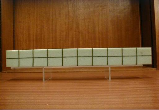
5 Example of Torsion
6 Example of Torsion For a non-circular section member or an open section member subjected to torsion: Plane cross sections of the member do not remain plane and the cross sections distort in a manner which is called warping. In other words, the fibers in the longitudinal direction deform unequally.

7 Example of Torsion
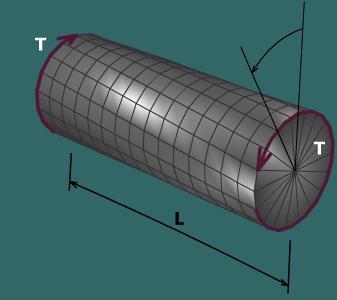
8 Example of Torsion For a circular shaft or a closed circular section member subjected to torsion: Plane circular cross sections remain plane and the cross sections at the ends of the member remain flat. The length and the radius of the member remain unchanged. Plane circular cross sections remain perpendicular to the longitudinal axis.
9 Analogy Between Axial Deformation and Torsion Axial Force (P) Elongation (d) Normal Stress (s) Extensional Strain (e) Modulus of Elasticity (E) Torque (T) Twist Angle (f) Shear Stress (t) Shear Strain (g) Shear Modulus (G)


10 Torsion Theory for circular sections

11 Absence of Warping
12 Investigate Deformation

13 Investigate Deformation

14 State of Pure Shear

15 Shear Strain Relate to Angel of Twist

16 Linear Variation of Shear Stress

17 Linear Variation of Shear Stress

18 Shear Stress Surfaces

19 Shear Stress Surfaces

20 Moment dm developed on da

21 Setup the Integration dm over the Area A

22 Relating Torque and Stress

23 Torsion Formula

24 J for Solid Circular Shape

25 J for Hollow Circular Shape
26 Angle of Twist Formula

27 Summery of Key Equations
28 Sign Conventions
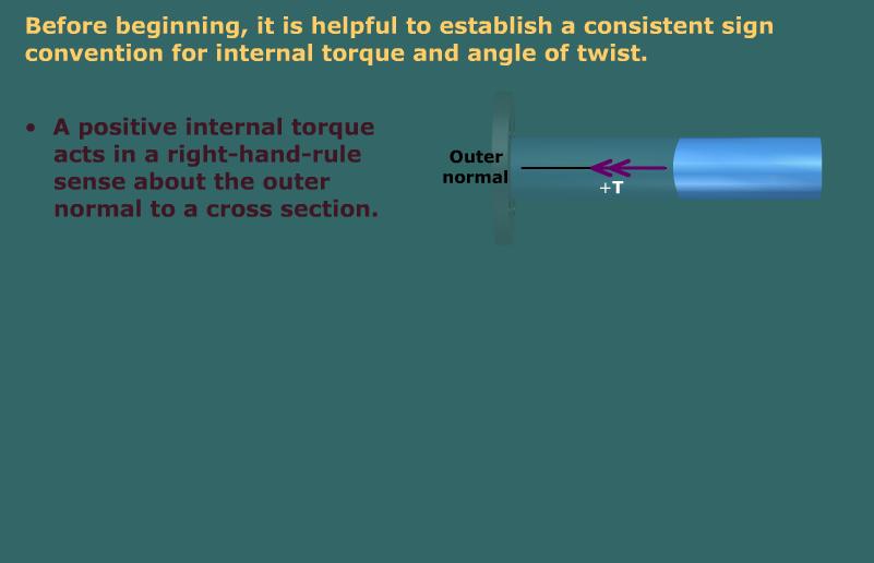
29 Sign Conventions
30 Sign Conventions
31 Sign Conventions

32 Example #1

33 Example #2

34 Example #3 The steel shaft of a socket wrench has a diameter of 8.0 mm. and a length of 200 mm (see figure). If the allowable stress in shear is 60 MPa, what is the maximum permissible torque T max that may be exerted with the wrench? Through what angle f (in degrees) will the shaft twist under the action of the maximum torque? (Assume G = 78 GPa and disregard any bending of the shaft.)

35 Example #4 A hollow steel shaft used in a construction auger has outer diameter d 2 =150 mm. and inner diameter d 1 = 115 mm. (see figure). The steel has shear modulus of elasticity G = 80 GPa For an applied torque of 17 kn.m, determine the following quantities: (a) shear stress t 2 at the outer surface of the shaft, (b) shear stress t 1 at the inner surface, and (c) rate of twist f (degrees per unit of length). Also, draw a diagram showing how the shear stresses vary in magnitude along a radial line in the cross section.
36 Example #5 A hollow aluminum tube used in a roof structure has an outside diameter d 2 =100 mm and an inside diameter d 1 =80 mm (see figure). The tube is 2.5 m long, and the aluminum has shear modulus G= 28 GPa. (a) If the tube is twisted in pure torsion by torques acting at the ends, what is the angle of twist f (in degrees) when the maximum shear stress is 50 MPa? (b) What diameter d is required for a solid shaft (see figure) to resist the same torque with the same maximum stress? (c) What is the ratio of the weight of the hollow tube to the weight of the solid shaft?
37 Example #6 Four gears are attached to a circular shaft and transmit the torques shown in the figure. The allowable shear stress in the shaft is 68 MPa. (a) What is the required diameter d of the shaft if it has a solid cross section? (a) What is the required outside diameter d if the shaft is hollow with an inside diameter of 25 mm?
38 Work Done and Power Transmitted When a force moves in a straight line with constant velocity the work done is given by the product the magnitude of the force and the distance through which it has moved. Work done = force distance The power transmitted by this action is defined as the rate at which this work is done, i.e. the work done in unit time. Power = work done time
39 Work Done and Power Transmitted The distance travelled by a rotating body is measured by the number of radians through which it rotates. The work done by a torque acting on a shaft is therefore given by the product of the magnitude of the torque and the amount of rotation in radians. For one revolutions of the shaft: The work done = T 2p (since the shaft turns through 2p radians in one revolution) If the shaft is rotating at N revolutions per minute, then work done = T 2p N (units of work per minute)
40 Work Done and Power Transmitted Usually the torque will measured in Newton meters (N.m) and therefore the units of work will also be N.m. However, it is more usual to give work in joules (J) which are equal numerically to Newton meters. 1 joule = 1 Newton meter Power is measured in watts (W), 1 W = 1 J/s = 1 N.m/s =(1/60) N.m/min
41 Work Done and Power Transmitted Hence, the power transmitted by a shaft rotating at N revolutions per minute and subject to torque of T (N.m) will be given by: Power T 2pN 60 Watts P T Tw P w 2pfT P 2pf w: the shaft s angular velocity (rad/s) : the frequency of shaft s rotation (Hz = 1 revolution/s) w 2pf rpm : revolutions per minute hp: horsepower, 1 hp = 746 W
 If the shaft has a diameter of 30 mm, what is the maximum shear stress t max in the shaft?")
42 Example #7 A motor drives a shaft at 12 Hz and delivers 20 kw of power (see figure). (a) If the shaft has a diameter of 30 mm, what is the maximum shear stress t max in the shaft? (b) If the maximum allowable shear stress is 40 MPa, what is the minimum permissible diameter d min of the shaft?
43 Example #8 The drive shaft for a truck (outer diameter 60 mm and inner diameter 40 mm) is running at 2500 rpm (see figure). (a) If the shaft transmits 150 kw, what is the maximum shear stress in the shaft? (b) If the allowable shear stress is 30 MPa, what is the maximum power that can be transmitted?
[7] Torsion. [7.1] Torsion. [7.2] Statically Indeterminate Torsion. [7] Torsion Page 1 of 21
![[7] Torsion. [7.1] Torsion. [7.2] Statically Indeterminate Torsion. [7] Torsion Page 1 of 21](/thumbs/88/115835122.jpg "[7] Torsion. [7.1] Torsion. [7.2] Statically Indeterminate Torsion. [7] Torsion Page 1 of 21") [7] Torsion Page 1 of 21 [7] Torsion [7.1] Torsion [7.2] Statically Indeterminate Torsion [7] Torsion Page 2 of 21 [7.1] Torsion SHEAR STRAIN DUE TO TORSION 1) A shaft with a circular cross section is
[7] Torsion Page 1 of 21 [7] Torsion [7.1] Torsion [7.2] Statically Indeterminate Torsion [7] Torsion Page 2 of 21 [7.1] Torsion SHEAR STRAIN DUE TO TORSION 1) A shaft with a circular cross section is
The problem of transmitting a torque or rotary motion from one plane to another is frequently encountered in machine design.
 CHAPER ORSION ORSION orsion refers to the twisting of a structural member when it is loaded by moments/torques that produce rotation about the longitudinal axis of the member he problem of transmitting
Chapter 5 Torsion STRUCTURAL MECHANICS: CE203. Notes are based on Mechanics of Materials: by R. C. Hibbeler, 7th Edition, Pearson
 STRUCTURAL MECHANICS: CE203 Chapter 5 Torsion Notes are based on Mechanics of Materials: by R. C. Hibbeler, 7th Edition, Pearson Dr B. Achour & Dr Eng. K. El-kashif Civil Engineering Department, University
Torsion Stresses in Tubes and Rods
 Torsion Stresses in Tubes and Rods This initial analysis is valid only for a restricted range of problem for which the assumptions are: Rod is initially straight. Rod twists without bending. Material is
Stress Analysis Lecture 3 ME 276 Spring Dr./ Ahmed Mohamed Nagib Elmekawy
 Stress Analysis Lecture 3 ME 276 Spring 2017-2018 Dr./ Ahmed Mohamed Nagib Elmekawy Axial Stress 2 Beam under the action of two tensile forces 3 Beam under the action of two tensile forces 4 Shear Stress
Mechanical Design in Optical Engineering
 Torsion Torsion: Torsion refers to the twisting of a structural member that is loaded by couples (torque) that produce rotation about the member s longitudinal axis. In other words, the member is loaded
The example of shafts; a) Rotating Machinery; Propeller shaft, Drive shaft b) Structural Systems; Landing gear strut, Flap drive mechanism
 Rotating Machinery; Propeller shaft, Drive shaft b) Structural Systems; Landing gear strut, Flap drive mechanism") TORSION OBJECTIVES: This chapter starts with torsion theory in the circular cross section followed by the behaviour of torsion member. The calculation of the stress stress and the angle of twist will be
TORSION OBJECTIVES: This chapter starts with torsion theory in the circular cross section followed by the behaviour of torsion member. The calculation of the stress stress and the angle of twist will be
MECE 3321: MECHANICS OF SOLIDS CHAPTER 5
 MECE 3321: MECHANICS OF SOLIDS CHAPTER 5 SAMANTHA RAMIREZ TORSION Torque A moment that tends to twist a member about its longitudinal axis 1 TORSIONAL DEFORMATION OF A CIRCULAR SHAFT Assumption If the
Structural Analysis I Chapter 4 - Torsion TORSION
 ORSION orsional stress results from the action of torsional or twisting moments acting about the longitudinal axis of a shaft. he effect of the application of a torsional moment, combined with appropriate
(48) CHAPTER 3: TORSION
 CHAPTER 3: TORSION") (48) CHAPTER 3: TORSION Introduction: In this chapter structural members and machine parts that are in torsion will be considered. More specifically, you will analyze the stresses and strains in members
(48) CHAPTER 3: TORSION Introduction: In this chapter structural members and machine parts that are in torsion will be considered. More specifically, you will analyze the stresses and strains in members
3.5 STRESS AND STRAIN IN PURE SHEAR. The next element is in a state of pure shear.
 3.5 STRESS AND STRAIN IN PURE SHEAR The next element is in a state of pure shear. Fig. 3-20 Stresses acting on a stress element cut from a bar in torsion (pure shear) Stresses on inclined planes Fig. 3-21
Chapter 5: Torsion. 1. Torsional Deformation of a Circular Shaft 2. The Torsion Formula 3. Power Transmission 4. Angle of Twist CHAPTER OBJECTIVES
 CHAPTER OBJECTIVES Chapter 5: Torsion Discuss effects of applying torsional loading to a long straight member (shaft or tube) Determine stress distribution within the member under torsional load Determine
EMA 3702 Mechanics & Materials Science (Mechanics of Materials) Chapter 3 Torsion
 Chapter 3 Torsion") EMA 3702 Mechanics & Materials Science (Mechanics of Materials) Chapter 3 Torsion Introduction Stress and strain in components subjected to torque T Circular Cross-section shape Material Shaft design Non-circular
EMA 3702 Mechanics & Materials Science (Mechanics of Materials) Chapter 3 Torsion Introduction Stress and strain in components subjected to torque T Circular Cross-section shape Material Shaft design Non-circular
Chapter Objectives. Copyright 2011 Pearson Education South Asia Pte Ltd
 Chapter Objectives To determine the torsional deformation of a perfectly elastic circular shaft. To determine the support reactions when these reactions cannot be determined solely from the moment equilibrium
MECHANICS OF MATERIALS
 2009 The McGraw-Hill Companies, Inc. All rights reserved. Fifth SI Edition CHAPTER 3 MECHANICS OF MATERIALS Ferdinand P. Beer E. Russell Johnston, Jr. John T. DeWolf David F. Mazurek Torsion Lecture Notes:
Sub. Code:
 Important Instructions to examiners: ) The answers should be examined by key words and not as word-to-word as given in the model answer scheme. ) The model answer and the answer written by candidate may
Torsion of shafts with circular symmetry
 orsion of shafts with circular symmetry Introduction Consider a uniform bar which is subject to a torque, eg through the action of two forces F separated by distance d, hence Fd orsion is the resultant
PES Institute of Technology
 PES Institute of Technology Bangalore south campus, Bangalore-5460100 Department of Mechanical Engineering Faculty name : Madhu M Date: 29/06/2012 SEM : 3 rd A SEC Subject : MECHANICS OF MATERIALS Subject
3 Hours/100 Marks Seat No.
 *17304* 17304 14115 3 Hours/100 Marks Seat No. Instructions : (1) All questions are compulsory. (2) Illustrate your answers with neat sketches wherever necessary. (3) Figures to the right indicate full
Torsion of Shafts Learning objectives
 Torsion of Shafts Shafts are structural members with length significantly greater than the largest cross-sectional dimension used in transmitting torque from one plane to another. Learning objectives Understand
PDDC 1 st Semester Civil Engineering Department Assignments of Mechanics of Solids [ ] Introduction, Fundamentals of Statics
![PDDC 1 st Semester Civil Engineering Department Assignments of Mechanics of Solids [ ] Introduction, Fundamentals of Statics](/thumbs/92/109382806.jpg "PDDC 1 st Semester Civil Engineering Department Assignments of Mechanics of Solids [ ] Introduction, Fundamentals of Statics") Page1 PDDC 1 st Semester Civil Engineering Department Assignments of Mechanics of Solids [2910601] Introduction, Fundamentals of Statics 1. Differentiate between Scalar and Vector quantity. Write S.I.
Page1 PDDC 1 st Semester Civil Engineering Department Assignments of Mechanics of Solids [2910601] Introduction, Fundamentals of Statics 1. Differentiate between Scalar and Vector quantity. Write S.I.
M. Vable Mechanics of Materials: Chapter 5. Torsion of Shafts
 Torsion of Shafts Shafts are structural members with length significantly greater than the largest cross-sectional dimension used in transmitting torque from one plane to another. Learning objectives Understand
R13. II B. Tech I Semester Regular Examinations, Jan MECHANICS OF SOLIDS (Com. to ME, AME, AE, MTE) PART-A
 PART-A") SET - 1 II B. Tech I Semester Regular Examinations, Jan - 2015 MECHANICS OF SOLIDS (Com. to ME, AME, AE, MTE) Time: 3 hours Max. Marks: 70 Note: 1. Question Paper consists of two parts (Part-A and Part-B)
SET - 1 II B. Tech I Semester Regular Examinations, Jan - 2015 MECHANICS OF SOLIDS (Com. to ME, AME, AE, MTE) Time: 3 hours Max. Marks: 70 Note: 1. Question Paper consists of two parts (Part-A and Part-B)
WORCESTER POLYTECHNIC INSTITUTE
 WORCESTER POLYTECHNIC INSTITUTE MECHANICAL ENGINEERING DEPARTMENT STRESS ANALYSIS ES-2502, C 2012 Lecture 17: 10 February 2012 General information Instructor: Cosme Furlong HL-151 (508) 831-5126 cfurlong@wpi.edu
MAAE 2202 A. Come to the PASS workshop with your mock exam complete. During the workshop you can work with other students to review your work.
 It is most beneficial to you to write this mock final exam UNDER EXAM CONDITIONS. This means: Complete the exam in 3 hours. Work on your own. Keep your textbook closed. Attempt every question. After the
QUESTION BANK SEMESTER: III SUBJECT NAME: MECHANICS OF SOLIDS
 QUESTION BANK SEMESTER: III SUBJECT NAME: MECHANICS OF SOLIDS UNIT 1- STRESS AND STRAIN PART A (2 Marks) 1. Define longitudinal strain and lateral strain. 2. State Hooke s law. 3. Define modular ratio,
MECHANICS OF MATERIALS
 GE SI CHAPTER 3 MECHANICS OF MATERIALS Ferdinand P. Beer E. Russell Johnston, Jr. John T. DeWolf David F. Mazurek Torsion Lecture Notes: J. Walt Oler Texas Tech University Torsional Loads on Circular Shafts
MECHANICS OF SOLIDS TORSION - TUTORIAL 1. You should judge your progress by completing the self assessment exercises.
 MECHANICS OF SOIS TORSION - TUTORIA 1 You should judge your progress by completing the self assessment exercises. On completion of this tutorial you should be able to do the following. erive the torsion
SRI CHANDRASEKHARENDRA SARASWATHI VISWA MAHAVIDHYALAYA
 SRI CHANDRASEKHARENDRA SARASWATHI VISWA MAHAVIDHYALAYA (Declared as Deemed-to-be University under Section 3 of the UGC Act, 1956, Vide notification No.F.9.9/92-U-3 dated 26 th May 1993 of the Govt. of
Experiment Two (2) Torsional testing of Circular Shafts
 Torsional testing of Circular Shafts") Experiment Two (2) Torsional testing of Circular Shafts Introduction: Torsion occurs when any shaft is subjected to a torque. This is true whether the shaft is rotating (such as drive shafts on engines,
Experiment Two (2) Torsional testing of Circular Shafts Introduction: Torsion occurs when any shaft is subjected to a torque. This is true whether the shaft is rotating (such as drive shafts on engines,
Sample Question Paper
 Scheme I Sample Question Paper Program Name : Mechanical Engineering Program Group Program Code : AE/ME/PG/PT/FG Semester : Third Course Title : Strength of Materials Marks : 70 Time: 3 Hrs. Instructions:
QUESTION BANK DEPARTMENT: CIVIL SEMESTER: III SUBJECT CODE: CE2201 SUBJECT NAME: MECHANICS OF SOLIDS UNIT 1- STRESS AND STRAIN PART A
 DEPARTMENT: CIVIL SUBJECT CODE: CE2201 QUESTION BANK SEMESTER: III SUBJECT NAME: MECHANICS OF SOLIDS UNIT 1- STRESS AND STRAIN PART A (2 Marks) 1. Define longitudinal strain and lateral strain. 2. State
5. What is the moment of inertia about the x - x axis of the rectangular beam shown?
 1 of 5 Continuing Education Course #274 What Every Engineer Should Know About Structures Part D - Bending Strength Of Materials NOTE: The following question was revised on 15 August 2018 1. The moment
[5] Stress and Strain
![[5] Stress and Strain](/thumbs/95/123344550.jpg "[5] Stress and Strain") [5] Stress and Strain Page 1 of 34 [5] Stress and Strain [5.1] Internal Stress of Solids [5.2] Design of Simple Connections (will not be covered in class) [5.3] Deformation and Strain [5.4] Hooke s Law
[5] Stress and Strain Page 1 of 34 [5] Stress and Strain [5.1] Internal Stress of Solids [5.2] Design of Simple Connections (will not be covered in class) [5.3] Deformation and Strain [5.4] Hooke s Law
D : SOLID MECHANICS. Q. 1 Q. 9 carry one mark each.
 GTE 2016 Q. 1 Q. 9 carry one mark each. D : SOLID MECHNICS Q.1 single degree of freedom vibrating system has mass of 5 kg, stiffness of 500 N/m and damping coefficient of 100 N-s/m. To make the system
MECHANICS LAB AM 317 EXP 4 TORSION OF CIRCULAR RODS
 MECHANICS LAB AM 317 EXP 4 TORSION OF CIRCULAR RODS I. OBJECTIVES I.1 To become familiar with torsion tests of rods with solid circular cross sections. I.2 To observe the relation between shear stress
UNIT-I STRESS, STRAIN. 1. A Member A B C D is subjected to loading as shown in fig determine the total elongation. Take E= 2 x10 5 N/mm 2
 UNIT-I STRESS, STRAIN 1. A Member A B C D is subjected to loading as shown in fig determine the total elongation. Take E= 2 x10 5 N/mm 2 Young s modulus E= 2 x10 5 N/mm 2 Area1=900mm 2 Area2=400mm 2 Area3=625mm
Downloaded from Downloaded from / 1
 PURWANCHAL UNIVERSITY III SEMESTER FINAL EXAMINATION-2002 LEVEL : B. E. (Civil) SUBJECT: BEG256CI, Strength of Material Full Marks: 80 TIME: 03:00 hrs Pass marks: 32 Candidates are required to give their
Members Subjected to Torsional Loads
 Members Subjected to Torsional Loads Torsion of circular shafts Definition of Torsion: Consider a shaft rigidly clamped at one end and twisted at the other end by a torque T = F.d applied in a plane perpendicular
Strength of Materials Prof S. K. Bhattacharya Department of Civil Engineering Indian Institute of Technology, Kharagpur Lecture - 18 Torsion - I
 Strength of Materials Prof S. K. Bhattacharya Department of Civil Engineering Indian Institute of Technology, Kharagpur Lecture - 18 Torsion - I Welcome to the first lesson of Module 4 which is on Torsion
Mechanical Engineering Ph.D. Preliminary Qualifying Examination Solid Mechanics February 25, 2002
 student personal identification (ID) number on each sheet. Do not write your name on any sheet. #1. A homogeneous, isotropic, linear elastic bar has rectangular cross sectional area A, modulus of elasticity
Chapter 3. Load and Stress Analysis. Lecture Slides
 Lecture Slides Chapter 3 Load and Stress Analysis 2015 by McGraw Hill Education. This is proprietary material solely for authorized instructor use. Not authorized for sale or distribution in any manner.
High Tech High Top Hat Technicians. An Introduction to Solid Mechanics. Is that supposed to bend there?
 High Tech High Top Hat Technicians An Introduction to Solid Mechanics Or Is that supposed to bend there? Why don't we fall through the floor? The power of any Spring is in the same proportion with the
Tuesday, February 11, Chapter 3. Load and Stress Analysis. Dr. Mohammad Suliman Abuhaiba, PE
 1 Chapter 3 Load and Stress Analysis 2 Chapter Outline Equilibrium & Free-Body Diagrams Shear Force and Bending Moments in Beams Singularity Functions Stress Cartesian Stress Components Mohr s Circle for
Solution: The strain in the bar is: ANS: E =6.37 GPa Poison s ration for the material is:
 Problem 10.4 A prismatic bar with length L 6m and a circular cross section with diameter D 0.0 m is subjected to 0-kN compressive forces at its ends. The length and diameter of the deformed bar are measured
Advanced Structural Analysis EGF Section Properties and Bending
 Advanced Structural Analysis EGF316 3. Section Properties and Bending 3.1 Loads in beams When we analyse beams, we need to consider various types of loads acting on them, for example, axial forces, shear
NAME: Given Formulae: Law of Cosines: Law of Sines:
 NME: Given Formulae: Law of Cosines: EXM 3 PST PROBLEMS (LESSONS 21 TO 28) 100 points Thursday, November 16, 2017, 7pm to 9:30, Room 200 You are allowed to use a calculator and drawing equipment, only.
KINGS COLLEGE OF ENGINEERING DEPARTMENT OF MECHANICAL ENGINEERING QUESTION BANK. Subject code/name: ME2254/STRENGTH OF MATERIALS Year/Sem:II / IV
 KINGS COLLEGE OF ENGINEERING DEPARTMENT OF MECHANICAL ENGINEERING QUESTION BANK Subject code/name: ME2254/STRENGTH OF MATERIALS Year/Sem:II / IV UNIT I STRESS, STRAIN DEFORMATION OF SOLIDS PART A (2 MARKS)
PROBLEM 3.3 ( )(45 10 ) T 5.17 kn m. A c c. 2 J c, (2)( ) 2 ( ) mm ( )
(45 10 ) T 5.17 kn m. A c c. 2 J c, (2)( ) 2 ( ) mm ( )") 0 mm PROEM..4 m 45 mm (a) Determine the torque that causes a maximum shearing stress of 45 MPa in the hollow cylindrical steel shaft shown. Determine the maximum shearing stress caused by the same torque
0 mm PROEM..4 m 45 mm (a) Determine the torque that causes a maximum shearing stress of 45 MPa in the hollow cylindrical steel shaft shown. Determine the maximum shearing stress caused by the same torque
COURSE TITLE : THEORY OF STRUCTURES -I COURSE CODE : 3013 COURSE CATEGORY : B PERIODS/WEEK : 6 PERIODS/SEMESTER: 90 CREDITS : 6
 COURSE TITLE : THEORY OF STRUCTURES -I COURSE CODE : 0 COURSE CATEGORY : B PERIODS/WEEK : 6 PERIODS/SEMESTER: 90 CREDITS : 6 TIME SCHEDULE Module Topics Period Moment of forces Support reactions Centre
twenty one concrete construction: shear & deflection ARCHITECTURAL STRUCTURES: FORM, BEHAVIOR, AND DESIGN DR. ANNE NICHOLS SUMMER 2014 lecture
 ARCHITECTURAL STRUCTURES: FORM, BEHAVIOR, AND DESIGN DR. ANNE NICHOLS SUMMER 2014 lecture twenty one concrete construction: Copyright Kirk Martini shear & deflection Concrete Shear 1 Shear in Concrete
Aluminum shell. Brass core. 40 in
 PROBLEM #1 (22 points) A solid brass core is connected to a hollow rod made of aluminum. Both are attached at each end to a rigid plate as shown in Fig. 1. The moduli of aluminum and brass are EA=11,000
MECHANICS OF MATERIALS Design of a Transmission Shaft
 Design of a Transmission Shaft If power is transferred to and from the shaft by gears or sprocket wheels, the shaft is subjected to transverse loading as well as shear loading. Normal stresses due to transverse
MARKS DISTRIBUTION AS PER CHAPTER (QUESTION ASKED IN GTU EXAM) Name Of Chapter. Applications of. Friction. Centroid & Moment.
 Name Of Chapter. Applications of. Friction. Centroid & Moment.") Introduction Fundamentals of statics Applications of fundamentals of statics Friction Centroid & Moment of inertia Simple Stresses & Strain Stresses in Beam Torsion Principle Stresses DEPARTMENT OF CIVIL
Introduction Fundamentals of statics Applications of fundamentals of statics Friction Centroid & Moment of inertia Simple Stresses & Strain Stresses in Beam Torsion Principle Stresses DEPARTMENT OF CIVIL
Mechanics of Materials II. Chapter III. A review of the fundamental formulation of stress, strain, and deflection
 Mechanics of Materials II Chapter III A review of the fundamental formulation of stress, strain, and deflection Outline Introduction Assumtions and limitations Axial loading Torsion of circular shafts
PERIYAR CENTENARY POLYTECHNIC COLLEGE PERIYAR NAGAR - VALLAM THANJAVUR. DEPARTMENT OF MECHANICAL ENGINEERING QUESTION BANK
 PERIYAR CENTENARY POLYTECHNIC COLLEGE PERIYAR NAGAR - VALLAM - 613 403 - THANJAVUR. DEPARTMENT OF MECHANICAL ENGINEERING QUESTION BANK Sub : Strength of Materials Year / Sem: II / III Sub Code : MEB 310
2. Polar moment of inertia As stated above, the polar second moment of area, J is defined as. Sample copy
 GATE PATHSHALA - 91. Polar moment of inertia As stated above, the polar second moment of area, is defined as z π r dr 0 R r π R π D For a solid shaft π (6) QP 0 π d Solid shaft π d Hollow shaft, " ( do
ME Final Exam. PROBLEM NO. 4 Part A (2 points max.) M (x) y. z (neutral axis) beam cross-sec+on. 20 kip ft. 0.2 ft. 10 ft. 0.1 ft.
 M (x) y. z (neutral axis) beam cross-sec+on. 20 kip ft. 0.2 ft. 10 ft. 0.1 ft.") ME 323 - Final Exam Name December 15, 2015 Instructor (circle) PROEM NO. 4 Part A (2 points max.) Krousgrill 11:30AM-12:20PM Ghosh 2:30-3:20PM Gonzalez 12:30-1:20PM Zhao 4:30-5:20PM M (x) y 20 kip ft 0.2
ME 323 - Final Exam Name December 15, 2015 Instructor (circle) PROEM NO. 4 Part A (2 points max.) Krousgrill 11:30AM-12:20PM Ghosh 2:30-3:20PM Gonzalez 12:30-1:20PM Zhao 4:30-5:20PM M (x) y 20 kip ft 0.2
SSC-JE MAINS ONLINE TEST SERIES / CIVIL ENGINEERING SOM + TOS
 SSC-JE MAINS ONLINE TEST SERIES / CIVIL ENGINEERING SOM + TOS Time Allowed:2 Hours Maximum Marks: 300 Attention: 1. Paper consists of Part A (Civil & Structural) Part B (Electrical) and Part C (Mechanical)
Stress Analysis Lecture 4 ME 276 Spring Dr./ Ahmed Mohamed Nagib Elmekawy
 Stress Analysis Lecture 4 ME 76 Spring 017-018 Dr./ Ahmed Mohamed Nagib Elmekawy Shear and Moment Diagrams Beam Sign Convention The positive directions are as follows: The internal shear force causes a
1 of 12. Given: Law of Cosines: C. Law of Sines: Stress = E = G
 ES230 STRENGTH OF MATERIALS FINAL EXAM: WEDNESDAY, MAY 15 TH, 4PM TO 7PM, AEC200 Closed book. Calculator and writing supplies allowed. Protractor and compass required. 180 Minute Time Limit You must have
2. Determine the deflection at C of the beam given in fig below. Use principal of virtual work. W L/2 B A L C
 CE-1259, Strength of Materials UNIT I STRESS, STRAIN DEFORMATION OF SOLIDS Part -A 1. Define strain energy density. 2. State Maxwell s reciprocal theorem. 3. Define proof resilience. 4. State Castigliano
UNIT 1 STRESS STRAIN AND DEFORMATION OF SOLIDS, STATES OF STRESS 1. Define stress. When an external force acts on a body, it undergoes deformation.
 UNIT 1 STRESS STRAIN AND DEFORMATION OF SOLIDS, STATES OF STRESS 1. Define stress. When an external force acts on a body, it undergoes deformation. At the same time the body resists deformation. The magnitude
AERO 214. Lab II. Measurement of elastic moduli using bending of beams and torsion of bars
 AERO 214 Lab II. Measurement of elastic moduli using bending of beams and torsion of bars BENDING EXPERIMENT Introduction Flexural properties of materials are of interest to engineers in many different
STRENGTH OF MATERIALS-I. Unit-1. Simple stresses and strains
 STRENGTH OF MATERIALS-I Unit-1 Simple stresses and strains 1. What is the Principle of surveying 2. Define Magnetic, True & Arbitrary Meridians. 3. Mention different types of chains 4. Differentiate between
Objectives. Power in Translational Systems 298 CHAPTER 6 POWER
 Objectives Explain the relationship between power and work. Explain the relationship between power, force, and speed for an object in translational motion. Calculate a device s efficiency in terms of the
ME325 EXAM I (Sample)
") ME35 EXAM I (Sample) NAME: NOTE: COSED BOOK, COSED NOTES. ONY A SINGE 8.5x" ORMUA SHEET IS AOWED. ADDITIONA INORMATION IS AVAIABE ON THE AST PAGE O THIS EXAM. DO YOUR WORK ON THE EXAM ONY (NO SCRATCH PAPER
ME35 EXAM I (Sample) NAME: NOTE: COSED BOOK, COSED NOTES. ONY A SINGE 8.5x" ORMUA SHEET IS AOWED. ADDITIONA INORMATION IS AVAIABE ON THE AST PAGE O THIS EXAM. DO YOUR WORK ON THE EXAM ONY (NO SCRATCH PAPER
This chapter is devoted to the study of torsion and of the stresses and deformations it causes. In the jet engine shown here, the central shaft links
 his chapter is devoted to the study of torsion and of the stresses and deformations it causes. In the jet engine shown here, the central shaft links the components of the engine to develop the thrust that
18.Define the term modulus of resilience. May/June Define Principal Stress. 20. Define Hydrostatic Pressure.
 CE6306 STREGNTH OF MATERIALS Question Bank Unit-I STRESS, STRAIN, DEFORMATION OF SOLIDS PART-A 1. Define Poison s Ratio May/June 2009 2. What is thermal stress? May/June 2009 3. Estimate the load carried
University of Pretoria Department of Mechanical & Aeronautical Engineering MOW 227, 2 nd Semester 2014
 Universit of Pretoria Department of Mechanical & Aeronautical Engineering MOW 7, nd Semester 04 Semester Test Date: August, 04 Total: 00 Internal eaminer: Duration: hours Mr. Riaan Meeser Instructions:
TORSION TEST. Figure 1 Schematic view of torsion test
 TORSION TEST 1. THE PURPOSE OF THE TEST The torsion test is performed for determining the properties of materials like shear modulus (G) and shear yield stress ( A ). 2. IDENTIFICATIONS: Shear modulus:
Solid Mechanics Chapter 1: Tension, Compression and Shear
 Solid Mechanics Chapter 1: Tension, Compression and Shear Dr. Imran Latif Department of Civil and Environmental Engineering College of Engineering University of Nizwa (UoN) 1 Why do we study Mechanics
OUTCOME 1 - TUTORIAL 3 BENDING MOMENTS. You should judge your progress by completing the self assessment exercises. CONTENTS
 Unit 2: Unit code: QCF Level: 4 Credit value: 15 Engineering Science L/601/1404 OUTCOME 1 - TUTORIAL 3 BENDING MOMENTS 1. Be able to determine the behavioural characteristics of elements of static engineering
ROTATING RING. Volume of small element = Rdθbt if weight density of ring = ρ weight of small element = ρrbtdθ. Figure 1 Rotating ring
 ROTATIONAL STRESSES INTRODUCTION High centrifugal forces are developed in machine components rotating at a high angular speed of the order of 100 to 500 revolutions per second (rps). High centrifugal force
STRESS, STRAIN AND DEFORMATION OF SOLIDS
 VELAMMAL COLLEGE OF ENGINEERING AND TECHNOLOGY, MADURAI 625009 DEPARTMENT OF CIVIL ENGINEERING CE8301 STRENGTH OF MATERIALS I -------------------------------------------------------------------------------------------------------------------------------
NORMAL STRESS. The simplest form of stress is normal stress/direct stress, which is the stress perpendicular to the surface on which it acts.
 NORMAL STRESS The simplest form of stress is normal stress/direct stress, which is the stress perpendicular to the surface on which it acts. σ = force/area = P/A where σ = the normal stress P = the centric
EDEXCEL NATIONAL CERTIFICATE/DIPLOMA SCIENCE FOR TECHNICIANS OUTCOME 1 - STATIC AND DYNAMIC FORCES TUTORIAL 3 STRESS AND STRAIN
 EDEXCEL NATIONAL CERTIFICATE/DIPLOMA SCIENCE FOR TECHNICIANS OUTCOME 1 - STATIC AND DYNAMIC FORCES TUTORIAL 3 STRESS AND STRAIN 1 Static and dynamic forces Forces: definitions of: matter, mass, weight,
CIVIL DEPARTMENT MECHANICS OF STRUCTURES- ASSIGNMENT NO 1. Brach: CE YEAR:
 MECHANICS OF STRUCTURES- ASSIGNMENT NO 1 SEMESTER: V 1) Find the least moment of Inertia about the centroidal axes X-X and Y-Y of an unequal angle section 125 mm 75 mm 10 mm as shown in figure 2) Determine
Chapter 8 Structural Design and Analysis. Strength and stiffness 5 types of load: Tension Compression Shear Bending Torsion
 Chapter 8 Structural Design and Analysis 1 Strength and stiffness 5 types of load: Tension Compression Shear Bending Torsion Normal Stress Stress is a state when a material is loaded. For normal forces
MECHANICS OF MATERIALS
 Third E CHAPTER 2 Stress MECHANICS OF MATERIALS Ferdinand P. Beer E. Russell Johnston, Jr. John T. DeWolf Lecture Notes: J. Walt Oler Texas Tech University and Strain Axial Loading Contents Stress & Strain:
Chapter Objectives. Copyright 2011 Pearson Education South Asia Pte Ltd
 Chapter Objectives To generalize the procedure by formulating equations that can be plotted so that they describe the internal shear and moment throughout a member. To use the relations between distributed
BE Semester- I ( ) Question Bank (MECHANICS OF SOLIDS)
 Question Bank (MECHANICS OF SOLIDS)") BE Semester- I ( ) Question Bank (MECHANICS OF SOLIDS) All questions carry equal marks(10 marks) Q.1 (a) Write the SI units of following quantities and also mention whether it is scalar or vector: (i)
BE Semester- I ( ) Question Bank (MECHANICS OF SOLIDS) All questions carry equal marks(10 marks) Q.1 (a) Write the SI units of following quantities and also mention whether it is scalar or vector: (i)
ME311 Machine Design
 ME311 Machine Design Lecture : Materials; Stress & Strain; Power Transmission W Dornfeld 13Sep018 airfield University School of Engineering Stress-Strain Curve for Ductile Material Ultimate Tensile racture
Chapter 1 General Introduction Instructor: Dr. Mürüde Çelikağ Office : CE Building Room CE230 and GE241
 CIVL222 STRENGTH OF MATERIALS Chapter 1 General Introduction Instructor: Dr. Mürüde Çelikağ Office : CE Building Room CE230 and GE241 E-mail : murude.celikag@emu.edu.tr 1. INTRODUCTION There are three
Only for Reference Page 1 of 18
 Only for Reference www.civilpddc2013.weebly.com Page 1 of 18 Seat No.: Enrolment No. GUJARAT TECHNOLOGICAL UNIVERSITY PDDC - SEMESTER II EXAMINATION WINTER 2013 Subject Code: X20603 Date: 26-12-2013 Subject
Structural Metals Lab 1.2. Torsion Testing of Structural Metals. Standards ASTM E143: Shear Modulus at Room Temperature
 Torsion Testing of Structural Metals Standards ASTM E143: Shear Modulus at Room Temperature Purpose To determine the shear modulus of structural metals Equipment Tinius-Olsen Lo-Torq Torsion Machine (figure
MECE 3321: Mechanics of Solids Chapter 6
 MECE 3321: Mechanics of Solids Chapter 6 Samantha Ramirez Beams Beams are long straight members that carry loads perpendicular to their longitudinal axis Beams are classified by the way they are supported
STRESS STRAIN AND DEFORMATION OF SOLIDS, STATES OF STRESS
 1 UNIT I STRESS STRAIN AND DEFORMATION OF SOLIDS, STATES OF STRESS 1. Define: Stress When an external force acts on a body, it undergoes deformation. At the same time the body resists deformation. The
Shafts: Torsion of Circular Shafts Reading: Crandall, Dahl and Lardner 6.2, 6.3
 M9 Shafts: Torsion of Circular Shafts Reading: Crandall, Dahl and Lardner 6., 6.3 A shaft is a structural member which is long and slender and subject to a torque (moment) acting about its long axis. We
CE6306 STRENGTH OF MATERIALS TWO MARK QUESTIONS WITH ANSWERS ACADEMIC YEAR
 CE6306 STRENGTH OF MATERIALS TWO MARK QUESTIONS WITH ANSWERS ACADEMIC YEAR 2014-2015 UNIT - 1 STRESS, STRAIN AND DEFORMATION OF SOLIDS PART- A 1. Define tensile stress and tensile strain. The stress induced
Chapter 3. Inertia. Force. Free Body Diagram. Net Force. Mass. quantity of matter composing a body represented by m. units are kg
 Chapter 3 Mass quantity of matter composing a body represented by m Kinetic Concepts for Analyzing Human Motion units are kg Inertia tendency to resist change in state of motion proportional to mass has
[8] Bending and Shear Loading of Beams
![[8] Bending and Shear Loading of Beams](/thumbs/92/110949676.jpg "[8] Bending and Shear Loading of Beams") [8] Bending and Shear Loading of Beams Page 1 of 28 [8] Bending and Shear Loading of Beams [8.1] Bending of Beams (will not be covered in class) [8.2] Bending Strain and Stress [8.3] Shear in Straight
[8] Bending and Shear Loading of Beams Page 1 of 28 [8] Bending and Shear Loading of Beams [8.1] Bending of Beams (will not be covered in class) [8.2] Bending Strain and Stress [8.3] Shear in Straight
INSTITUTE OF AERONAUTICAL ENGINEERING (Autonomous) Dundigal, Hyderabad
 Dundigal, Hyderabad") INSTITUTE OF AERONAUTICAL ENGINEERING (Autonomous) Dundigal, Hyderabad -00 04 CIVIL ENGINEERING QUESTION BANK Course Name : STRENGTH OF MATERIALS II Course Code : A404 Class : II B. Tech II Semester Section
INSTITUTE OF AERONAUTICAL ENGINEERING (Autonomous) Dundigal, Hyderabad -00 04 CIVIL ENGINEERING QUESTION BANK Course Name : STRENGTH OF MATERIALS II Course Code : A404 Class : II B. Tech II Semester Section
Lab Exercise #3: Torsion
 Lab Exercise #3: Pre-lab assignment: Yes No Goals: 1. To evaluate the equations of angular displacement, shear stress, and shear strain for a shaft undergoing torsional stress. Principles: testing of round
A Study on the Tube of Integral Propeller Shaft for the Rear-wheel Drive Automobile Using Carbon Composite Fiber
 A Study on the Tube of Integral Propeller Shaft for the Rear-wheel Drive Automobile Using Carbon Composite Fiber Kibong Han Mechatronics Department, Jungwon University, 85 Munmu-ro, Goesan-gun, South Korea.
Solution: T, A1, A2, A3, L1, L2, L3, E1, E2, E3, P are known Five equations in five unknowns, F1, F2, F3, ua and va
 ME 323 Examination # 1 February 18, 2016 Name (Print) (Last) (First) Instructor PROBLEM #1 (20 points) A structure is constructed from members 1, 2 and 3, with these members made up of the same material
6. Bending CHAPTER OBJECTIVES
 CHAPTER OBJECTIVES Determine stress in members caused by bending Discuss how to establish shear and moment diagrams for a beam or shaft Determine largest shear and moment in a member, and specify where
4. SHAFTS. A shaft is an element used to transmit power and torque, and it can support
 4. SHAFTS A shaft is an element used to transmit power and torque, and it can support reverse bending (fatigue). Most shafts have circular cross sections, either solid or tubular. The difference between
2. Rigid bar ABC supports a weight of W = 50 kn. Bar ABC is pinned at A and supported at B by rod (1). What is the axial force in rod (1)?
. What is the axial force in rod (1)?") IDE 110 S08 Test 1 Name: 1. Determine the internal axial forces in segments (1), (2) and (3). (a) N 1 = kn (b) N 2 = kn (c) N 3 = kn 2. Rigid bar ABC supports a weight of W = 50 kn. Bar ABC is pinned at
IDE 110 S08 Test 1 Name: 1. Determine the internal axial forces in segments (1), (2) and (3). (a) N 1 = kn (b) N 2 = kn (c) N 3 = kn 2. Rigid bar ABC supports a weight of W = 50 kn. Bar ABC is pinned at
Engineering Science OUTCOME 1 - TUTORIAL 4 COLUMNS
 Unit 2: Unit code: QCF Level: Credit value: 15 Engineering Science L/601/10 OUTCOME 1 - TUTORIAL COLUMNS 1. Be able to determine the behavioural characteristics of elements of static engineering systems