Advanced Structural Analysis EGF Section Properties and Bending
|
|
|
- Amberlynn Webb
- 5 years ago
- Views:
Transcription


1 Advanced Structural Analysis EGF Section Properties and Bending 3.1 Loads in beams When we analyse beams, we need to consider various types of loads acting on them, for example, axial forces, shear forces, bending moments and torques. Any beam structure subjected to any or all of these loads have associated stresses. In order to compute the stresses, we need to know the nature of the cross-section of the beam. Before going into the details of stress calculations for beams, let us recap some preliminaries of beam bending. 3.2 Beam bending If the load is applied in such a way that the structure deforms perpendicular to the axis of the structure, then such a deformation behavior is called bending. When a beam is loaded and subsequently bends, its longitudinal axis is deformed into a curve. One side is extended and in state of tension whereas the other side is shortened and in a state of compression, as illustrated in Figure 1. Figure 1: State of bending If the loads cause the beam to sag, the upper surface of the beam is shorter that the lower surface and the opposite is true for hogging. Thus, the strains in the upper and lower portions of the beam are different, and knowing that stress is directly proportional to strain for linear elastic material, it follows that the stress varies through the depth of the beam. Consider an appropriately supported beam aligned with the -axis of the coordinate system, which is subjected to external loading such that it deflects in the -direction as shown in Figure 2. 1
2 Figure 2: Bending of beam. Source: Mechanics of Materisl, Beer, Johnston, DeWolf, Mazurek Stress analysis of the beam is based on some kinematical assumptions: The beam is slender (length >> thickness) Cross sections remain plane Cross sections remain normal to the beam axis (Bernoulli hypothesis) The beam material is linearly elastic (obeys Hooke s Law) and homogeneous Deformations and deflections are small In the figure above, the direct stress varies from compression in the upper fibers of the beam to tension in the lower. Logically, the direct stress is zero in the fibers that do not undergo a change in length and we call the plane containing these fibers the neutral plane. The line of intersection of the neutral plane and any cross-section of the beam is termed the neutral axis. The neutral axis denotes the material fiber parallel to the beam axis which, in pure bending, does not experience any elongation or compression. Our challenge therefore is to be able to determine the variation of direct stress through the depth of the beam, calculate the values of stresses and also find the corresponding beam deflection. The simple theory of elastic bending states that: Where : = applied bending moment (Nm or Nmm) = Second moment of area of cross-section (m 4 or mm 4 ) 2
 Thus for a simply supported beam with central load subject to pure bending: There is a linear variation in stress with")


3 σ = bending stress at (N/m 2 or MPa) = distance from neutral axis (m or mm) = Young s modulus for the material (N/m 2 or MPa) = Radius of curvature (m or mm) Thus for a simply supported beam with central load subject to pure bending: There is a linear variation in stress with distance from NA: 3.3 Recap on Some Simple Beam Types There are different types of beams depending upon the boundary conditions. The three shown below are some of the simplest. Cantilever Beam A cantilever beam is built in or fixed at one end and the other end is free to move. When a load is applied to the cantilever, a reaction and resisting moment occur at the fixed end. For a cantilever beam with end load it can be shown that: Simply Supported Beam A simply supported beam is supported at its ends on rollers or smooth surfaces, or with one of these combined with a pin at the other end. 3

 We then need to get the cross-section at the chosen position and find the relevant sectional properties - namely the centroid and the second moment of areas. 3.")
4 For a simply supported beam with a central load it can be shown that: Built in Beam A built-in beam is built in or fixed at both ends. For a built-in beam with central load it can be shown that: 3.4 Computing stresses due to Bending Steps in calculating the stresses in beams. 1.) As the bending moment changes along the length of a beam, we first need to choose a position along the beam at which to determine the stresses. 2.) We then need to get the cross-section at the chosen position and find the relevant sectional properties - namely the centroid and the second moment of areas. 3.) Then, we can calculate the corresponding stresses. 3.5 Centroid of Beam Cross Sections The weight of a body is an example of a distributed force in that any body can be considered to be made up of a number of particles each with weight. It is convenient to replace all of these individual weight forces by a single weight force with a magnitude equal to the sum of the magnitudes of all of the constituent weight forces. This equivalent weight force acts at a particular point called the centre of gravity. When considering a section of a constant crosssection beam, we use the term centroid instead of centre of gravity. 4


5 The centroid is important in calculations as it tells us where the neutral axis lies. If we bend a beam, the neutral axis is the plane on which there is no strain. Some sections have multiple neutral axis and they all pass through the centroid. Where would you anticipate the position of the centroid for the following shapes? The first moment of area of a section is a measure of the distribution of mass relative to an axis. First moment of area A about the -axis: First moment of area A about the -axis: The centroid is the point at which the first moment of area goes to zero for any orthogonal axis system. The centroid of a section can be located as shown below: 5

6 Rearranging: For symmetrical homogeneous bodies, the centroid is located at the geometric centre. For composite sections, it can be obtained by considering the object to be made up of constituent parts each having weight acting through their own centroid. For objects containing holes or cutouts, the hole is treated as a negative mass. We find the centroid relative to any arbitrary orthogonal axis. Then once we know the position of the centroid, we can carry out subsequent calculations relative to this. When considering discrete pieces of area, the integrals in the above equations can be replaced by a sum: 6


7 Example 1 Locate the centroid of the following shape: Recall: 7
8 8
9 3.6 Second Moments of Area The second moment of area (or moment of inertia) of a beam section is a measure of how far away the material is located from the neutral axis and therefore its resistance to bending. Thus the greater the second moment of area, the greater the bending moment needed to produce a given radius of curvature of the beam. In most cases, we would aim to maximize the second moments of area. The second moments of area are given by: Again, if the areas are discrete, we can replace these integrals by a sum: The quantities above are geometric properties and can be evaluated for any cross section and must be taken relative to the centroid. Clearly, they depend on the origin and the orientation of the coordinate system Some Useful Facts For a circular section: Where is the diameter. For a rectangular section: 9
10 Hence, for a square section (where ): 10

11 3.7 Parallel Axis Theorem For the calculation of second moments of areas of complex sections, it is often convenient to perform the additive decompositions of the integrals above. Divide the area into a series of simpler shapes and the second moment of area for the entire shape is the sum of the second moment of areas of all of its parts about a common axis with origin at the centroid of the overall shape. Consider the elbow section below: Firstly, the second moment of area of each rectangle needs to be calculated with respect to the global coordinate system. A convenient strategy for this calculation consists of three steps: 1. Locate the centroid of the overall section 2. Determine the second moments of area of the subsections with respect to their own local coordinate systems 3. Account for the shift of the coordinate axis We denote the coordinates of the centroid CA 1 of part 1 of the section with respect to the global system as and. We can then write: By definition, the - and -axes pass through the centroid CA 1 of subsection 1. Therefore, the remaining integral in the above disappears and we obtain: 11
12 Similarly: In the same way, we can show that in general: It follows that the overall second moments of area of the compound section are given by: When applying these equations, take care as and can be positive or negative. These relations are known as the parallel axis theorem. 12

13 Example 1 (continued): Calculate and Recall: And: 13
14 Note: and are always positive, but can be positive or negative. 14
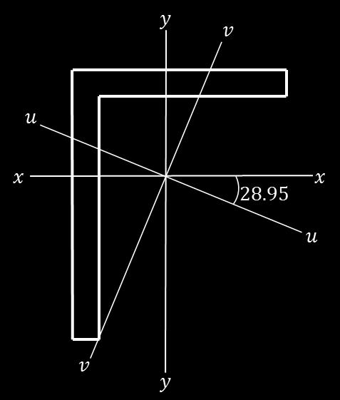
15 3.8 Principal Axis There always exists an orientation of the coordinate system such that associated coordinate axes are called the principal directions of the cross section.. The A principal axis is one where bending about one axis does not result in any deflection (and hence stress/strain) perpendicular to that axis. There is no interaction between the two axes. It follows that every axis of symmetry is a principal axis. The principal axes for an open section are not so obvious. We need to calculate: The angle,, of the principal axes relative to the and axes The second moments of area about principal axes, and It can be shown that: Where: is the second moment of area about the -axis is the second moment of area about the -axis is the product moment of area about the The angle and -axes is measured anticlockwise positive from the -axis And: Or: 15
16 Example 1 (continued) Calculate the second moments of area about principal axes, for the shape. We need to find. Recall: Finally we need to calculate and. Recall: Note and are always positive. 16
17 17
18 Example 2: A 50mm by 50mm square section steel cantilever beam is 1m long and supports an end load of 100N. Calculate the maximum bending stress and the maximum deflection in the beam. Assume a Young s modulus of 210GPa. Solution: 18

19 3.9 Unsymmetric (skew) Bending Symmetric bending occurs in beams whose cross-sections have single or double lines of symmetry, or when the applied load is skew. Our analysis so far has been limited to symmetric bending. This is when the - and -axes of the coordinate system have been assumed to coincide with the principal directions of the cross section. Every axis of symmetry of the section is a principal axis. It can be shown that for unsymmetrical bending, at a point is given by: as shown, the bending stress Where are the bending moments about the - and -axes, respectively. Where is the applied bending moment about the -axis. And where and are the coordinates of about the - and -axes: And and are the coordinates of about the - and -axes. 19

20 We have previously defined that the neutral axis in the line along which the stresses due to bending are zero: Therefore: 20
21 Example 1 (continued) Calculate the bending stress at Point if and locate the neutral axis. Recall: Then: 21

22 Therefore: And to locate the neutral axis: 22

23 3.10 Shear Centre We will not cover the shear centre in detail, but just to be aware of the meaning. Depending on the location of the applied forces in the cross-section, the section will be subjected to a certain amount of torsion/twisting. We define the shear center as that point in the cross-section through which the applied loads produce no twisting. Where a cross-section has an axis of symmetry, the shear center must lie on this axis Torsion of Circular Sections The twisting of a shaft about its longitudinal axis, due to an applied torque, is called torsion. When considering a circular shaft, the term pure torsion is used as the cross section of the shaft retains its shape. Here, we assume that circular sections remain circular and there is no change in diameter of the shaft. The relationship among various quantities is given by, where, = Applied torque (Nm or Nmm) = Polar moment of area of cross-section (m 4 or mm 4 ) τ = shear stress at r (N/m 2 or MPa) = radius (m or mm) = modulus of rigidity (N/m 2 or MPa) and is a function of the material given by θ= Twist per unit length (radians/m or/mm) L = Length of the shaft (m or mm) The shear stress is a function of, and which varies linearly with and does not depend on the material. There is a linear variation in shear stress with distance from centre: 23
24 Example 3: A 2m length of 20mm diameter steel bar is subjected to a torque of 5kNm. Calculate the maximum shear stress and the angle of twist. Assume a Young s modulus, Poisson s ratio and yield stress of 210 GPa, 0.3 and 300MPa respectively. Solution: For circular sections, we know that: Recall: Recall: So: And: Therefore: 24
PURE BENDING. If a simply supported beam carries two point loads of 10 kn as shown in the following figure, pure bending occurs at segment BC.
 BENDING STRESS The effect of a bending moment applied to a cross-section of a beam is to induce a state of stress across that section. These stresses are known as bending stresses and they act normally
[8] Bending and Shear Loading of Beams
![[8] Bending and Shear Loading of Beams](/thumbs/92/110949676.jpg "[8] Bending and Shear Loading of Beams") [8] Bending and Shear Loading of Beams Page 1 of 28 [8] Bending and Shear Loading of Beams [8.1] Bending of Beams (will not be covered in class) [8.2] Bending Strain and Stress [8.3] Shear in Straight
[8] Bending and Shear Loading of Beams Page 1 of 28 [8] Bending and Shear Loading of Beams [8.1] Bending of Beams (will not be covered in class) [8.2] Bending Strain and Stress [8.3] Shear in Straight
STRENGTH OF MATERIALS-I. Unit-1. Simple stresses and strains
 STRENGTH OF MATERIALS-I Unit-1 Simple stresses and strains 1. What is the Principle of surveying 2. Define Magnetic, True & Arbitrary Meridians. 3. Mention different types of chains 4. Differentiate between
UNIT 1 STRESS STRAIN AND DEFORMATION OF SOLIDS, STATES OF STRESS 1. Define stress. When an external force acts on a body, it undergoes deformation.
 UNIT 1 STRESS STRAIN AND DEFORMATION OF SOLIDS, STATES OF STRESS 1. Define stress. When an external force acts on a body, it undergoes deformation. At the same time the body resists deformation. The magnitude
STRESS STRAIN AND DEFORMATION OF SOLIDS, STATES OF STRESS
 1 UNIT I STRESS STRAIN AND DEFORMATION OF SOLIDS, STATES OF STRESS 1. Define: Stress When an external force acts on a body, it undergoes deformation. At the same time the body resists deformation. The
PES Institute of Technology
 PES Institute of Technology Bangalore south campus, Bangalore-5460100 Department of Mechanical Engineering Faculty name : Madhu M Date: 29/06/2012 SEM : 3 rd A SEC Subject : MECHANICS OF MATERIALS Subject
Lecture 15 Strain and stress in beams
 Spring, 2019 ME 323 Mechanics of Materials Lecture 15 Strain and stress in beams Reading assignment: 6.1 6.2 News: Instructor: Prof. Marcial Gonzalez Last modified: 1/6/19 9:42:38 PM Beam theory (@ ME
PDDC 1 st Semester Civil Engineering Department Assignments of Mechanics of Solids [ ] Introduction, Fundamentals of Statics
![PDDC 1 st Semester Civil Engineering Department Assignments of Mechanics of Solids [ ] Introduction, Fundamentals of Statics](/thumbs/92/109382806.jpg "PDDC 1 st Semester Civil Engineering Department Assignments of Mechanics of Solids [ ] Introduction, Fundamentals of Statics") Page1 PDDC 1 st Semester Civil Engineering Department Assignments of Mechanics of Solids [2910601] Introduction, Fundamentals of Statics 1. Differentiate between Scalar and Vector quantity. Write S.I.
Page1 PDDC 1 st Semester Civil Engineering Department Assignments of Mechanics of Solids [2910601] Introduction, Fundamentals of Statics 1. Differentiate between Scalar and Vector quantity. Write S.I.
Sub. Code:
 Important Instructions to examiners: ) The answers should be examined by key words and not as word-to-word as given in the model answer scheme. ) The model answer and the answer written by candidate may
MECHANICS OF MATERIALS
 STATICS AND MECHANICS OF MATERIALS Ferdinand P. Beer E. Russell Johnston, Jr, John T. DeWolf David E Mazurek \Cawect Mc / iur/» Craw SugomcT Hilt Introduction 1 1.1 What is Mechanics? 2 1.2 Fundamental
KINGS COLLEGE OF ENGINEERING DEPARTMENT OF MECHANICAL ENGINEERING QUESTION BANK. Subject code/name: ME2254/STRENGTH OF MATERIALS Year/Sem:II / IV
 KINGS COLLEGE OF ENGINEERING DEPARTMENT OF MECHANICAL ENGINEERING QUESTION BANK Subject code/name: ME2254/STRENGTH OF MATERIALS Year/Sem:II / IV UNIT I STRESS, STRAIN DEFORMATION OF SOLIDS PART A (2 MARKS)
QUESTION BANK SEMESTER: III SUBJECT NAME: MECHANICS OF SOLIDS
 QUESTION BANK SEMESTER: III SUBJECT NAME: MECHANICS OF SOLIDS UNIT 1- STRESS AND STRAIN PART A (2 Marks) 1. Define longitudinal strain and lateral strain. 2. State Hooke s law. 3. Define modular ratio,
QUESTION BANK DEPARTMENT: CIVIL SEMESTER: III SUBJECT CODE: CE2201 SUBJECT NAME: MECHANICS OF SOLIDS UNIT 1- STRESS AND STRAIN PART A
 DEPARTMENT: CIVIL SUBJECT CODE: CE2201 QUESTION BANK SEMESTER: III SUBJECT NAME: MECHANICS OF SOLIDS UNIT 1- STRESS AND STRAIN PART A (2 Marks) 1. Define longitudinal strain and lateral strain. 2. State
Stress Analysis Lecture 4 ME 276 Spring Dr./ Ahmed Mohamed Nagib Elmekawy
 Stress Analysis Lecture 4 ME 76 Spring 017-018 Dr./ Ahmed Mohamed Nagib Elmekawy Shear and Moment Diagrams Beam Sign Convention The positive directions are as follows: The internal shear force causes a
CHAPTER 4: BENDING OF BEAMS
 (74) CHAPTER 4: BENDING OF BEAMS This chapter will be devoted to the analysis of prismatic members subjected to equal and opposite couples M and M' acting in the same longitudinal plane. Such members are
Chapter 3. Load and Stress Analysis. Lecture Slides
 Lecture Slides Chapter 3 Load and Stress Analysis 2015 by McGraw Hill Education. This is proprietary material solely for authorized instructor use. Not authorized for sale or distribution in any manner.
6. Bending CHAPTER OBJECTIVES
 CHAPTER OBJECTIVES Determine stress in members caused by bending Discuss how to establish shear and moment diagrams for a beam or shaft Determine largest shear and moment in a member, and specify where
Consider an elastic spring as shown in the Fig.2.4. When the spring is slowly
 .3 Strain Energy Consider an elastic spring as shown in the Fig..4. When the spring is slowly pulled, it deflects by a small amount u 1. When the load is removed from the spring, it goes back to the original
CHAPTER -6- BENDING Part -1-
 Ishik University / Sulaimani Civil Engineering Department Mechanics of Materials CE 211 CHAPTER -6- BENDING Part -1-1 CHAPTER -6- Bending Outlines of this chapter: 6.1. Chapter Objectives 6.2. Shear and
Chapter 3. Load and Stress Analysis
 Chapter 3 Load and Stress Analysis 2 Shear Force and Bending Moments in Beams Internal shear force V & bending moment M must ensure equilibrium Fig. 3 2 Sign Conventions for Bending and Shear Fig. 3 3
Structural Analysis I Chapter 4 - Torsion TORSION
 ORSION orsional stress results from the action of torsional or twisting moments acting about the longitudinal axis of a shaft. he effect of the application of a torsional moment, combined with appropriate
Mechanical Design in Optical Engineering
 Torsion Torsion: Torsion refers to the twisting of a structural member that is loaded by couples (torque) that produce rotation about the member s longitudinal axis. In other words, the member is loaded
Chapter 6: Cross-Sectional Properties of Structural Members
 Chapter 6: Cross-Sectional Properties of Structural Members Introduction Beam design requires the knowledge of the following. Material strengths (allowable stresses) Critical shear and moment values Cross
OUTCOME 1 - TUTORIAL 3 BENDING MOMENTS. You should judge your progress by completing the self assessment exercises. CONTENTS
 Unit 2: Unit code: QCF Level: 4 Credit value: 15 Engineering Science L/601/1404 OUTCOME 1 - TUTORIAL 3 BENDING MOMENTS 1. Be able to determine the behavioural characteristics of elements of static engineering
Strength of Materials Prof. S.K.Bhattacharya Dept. of Civil Engineering, I.I.T., Kharagpur Lecture No.26 Stresses in Beams-I
 Strength of Materials Prof. S.K.Bhattacharya Dept. of Civil Engineering, I.I.T., Kharagpur Lecture No.26 Stresses in Beams-I Welcome to the first lesson of the 6th module which is on Stresses in Beams
Tuesday, February 11, Chapter 3. Load and Stress Analysis. Dr. Mohammad Suliman Abuhaiba, PE
 1 Chapter 3 Load and Stress Analysis 2 Chapter Outline Equilibrium & Free-Body Diagrams Shear Force and Bending Moments in Beams Singularity Functions Stress Cartesian Stress Components Mohr s Circle for
Mechanics of Solids notes
 Mechanics of Solids notes 1 UNIT II Pure Bending Loading restrictions: As we are aware of the fact internal reactions developed on any cross-section of a beam may consists of a resultant normal force,
BE Semester- I ( ) Question Bank (MECHANICS OF SOLIDS)
 Question Bank (MECHANICS OF SOLIDS)") BE Semester- I ( ) Question Bank (MECHANICS OF SOLIDS) All questions carry equal marks(10 marks) Q.1 (a) Write the SI units of following quantities and also mention whether it is scalar or vector: (i)
BE Semester- I ( ) Question Bank (MECHANICS OF SOLIDS) All questions carry equal marks(10 marks) Q.1 (a) Write the SI units of following quantities and also mention whether it is scalar or vector: (i)
Stresses in Curved Beam
 Stresses in Curved Beam Consider a curved beam subjected to bending moment M b as shown in the figure. The distribution of stress in curved flexural member is determined by using the following assumptions:
7.4 The Elementary Beam Theory
 7.4 The Elementary Beam Theory In this section, problems involving long and slender beams are addressed. s with pressure vessels, the geometry of the beam, and the specific type of loading which will be
MECE 3321: Mechanics of Solids Chapter 6
 MECE 3321: Mechanics of Solids Chapter 6 Samantha Ramirez Beams Beams are long straight members that carry loads perpendicular to their longitudinal axis Beams are classified by the way they are supported
FIXED BEAMS IN BENDING
 FIXED BEAMS IN BENDING INTRODUCTION Fixed or built-in beams are commonly used in building construction because they possess high rigidity in comparison to simply supported beams. When a simply supported
COURSE TITLE : APPLIED MECHANICS & STRENGTH OF MATERIALS COURSE CODE : 4017 COURSE CATEGORY : A PERIODS/WEEK : 6 PERIODS/ SEMESTER : 108 CREDITS : 5
 COURSE TITLE : APPLIED MECHANICS & STRENGTH OF MATERIALS COURSE CODE : 4017 COURSE CATEGORY : A PERIODS/WEEK : 6 PERIODS/ SEMESTER : 108 CREDITS : 5 TIME SCHEDULE MODULE TOPICS PERIODS 1 Simple stresses
UNIT- I Thin plate theory, Structural Instability:
 UNIT- I Thin plate theory, Structural Instability: Analysis of thin rectangular plates subject to bending, twisting, distributed transverse load, combined bending and in-plane loading Thin plates having
3 Hours/100 Marks Seat No.
 *17304* 17304 14115 3 Hours/100 Marks Seat No. Instructions : (1) All questions are compulsory. (2) Illustrate your answers with neat sketches wherever necessary. (3) Figures to the right indicate full
MECHANICS OF MATERIALS
 2009 The McGraw-Hill Companies, Inc. All rights reserved. Fifth SI Edition CHAPTER 3 MECHANICS OF MATERIALS Ferdinand P. Beer E. Russell Johnston, Jr. John T. DeWolf David F. Mazurek Torsion Lecture Notes:
PERIYAR CENTENARY POLYTECHNIC COLLEGE PERIYAR NAGAR - VALLAM THANJAVUR. DEPARTMENT OF MECHANICAL ENGINEERING QUESTION BANK
 PERIYAR CENTENARY POLYTECHNIC COLLEGE PERIYAR NAGAR - VALLAM - 613 403 - THANJAVUR. DEPARTMENT OF MECHANICAL ENGINEERING QUESTION BANK Sub : Strength of Materials Year / Sem: II / III Sub Code : MEB 310
Sample Question Paper
 Scheme I Sample Question Paper Program Name : Mechanical Engineering Program Group Program Code : AE/ME/PG/PT/FG Semester : Third Course Title : Strength of Materials Marks : 70 Time: 3 Hrs. Instructions:
R13. II B. Tech I Semester Regular Examinations, Jan MECHANICS OF SOLIDS (Com. to ME, AME, AE, MTE) PART-A
 PART-A") SET - 1 II B. Tech I Semester Regular Examinations, Jan - 2015 MECHANICS OF SOLIDS (Com. to ME, AME, AE, MTE) Time: 3 hours Max. Marks: 70 Note: 1. Question Paper consists of two parts (Part-A and Part-B)
SET - 1 II B. Tech I Semester Regular Examinations, Jan - 2015 MECHANICS OF SOLIDS (Com. to ME, AME, AE, MTE) Time: 3 hours Max. Marks: 70 Note: 1. Question Paper consists of two parts (Part-A and Part-B)
Properties of Sections
 ARCH 314 Structures I Test Primer Questions Dr.-Ing. Peter von Buelow Properties of Sections 1. Select all that apply to the characteristics of the Center of Gravity: A) 1. The point about which the body
COURSE TITLE : THEORY OF STRUCTURES -I COURSE CODE : 3013 COURSE CATEGORY : B PERIODS/WEEK : 6 PERIODS/SEMESTER: 90 CREDITS : 6
 COURSE TITLE : THEORY OF STRUCTURES -I COURSE CODE : 0 COURSE CATEGORY : B PERIODS/WEEK : 6 PERIODS/SEMESTER: 90 CREDITS : 6 TIME SCHEDULE Module Topics Period Moment of forces Support reactions Centre
 UNIT III DEFLECTION OF BEAMS 1. What are the methods for finding out the slope and deflection at a section? The important methods used for finding out the slope and deflection at a section in a loaded
MECHANICS OF MATERIALS. Analysis of Beams for Bending
 MECHANICS OF MATERIALS Analysis of Beams for Bending By NUR FARHAYU ARIFFIN Faculty of Civil Engineering & Earth Resources Chapter Description Expected Outcomes Define the elastic deformation of an axially
UNSYMMETRICAL BENDING
 UNSYMMETRICAL BENDING The general bending stress equation for elastic, homogeneous beams is given as (II.1) where Mx and My are the bending moments about the x and y centroidal axes, respectively. Ix and
ME Final Exam. PROBLEM NO. 4 Part A (2 points max.) M (x) y. z (neutral axis) beam cross-sec+on. 20 kip ft. 0.2 ft. 10 ft. 0.1 ft.
 M (x) y. z (neutral axis) beam cross-sec+on. 20 kip ft. 0.2 ft. 10 ft. 0.1 ft.") ME 323 - Final Exam Name December 15, 2015 Instructor (circle) PROEM NO. 4 Part A (2 points max.) Krousgrill 11:30AM-12:20PM Ghosh 2:30-3:20PM Gonzalez 12:30-1:20PM Zhao 4:30-5:20PM M (x) y 20 kip ft 0.2
ME 323 - Final Exam Name December 15, 2015 Instructor (circle) PROEM NO. 4 Part A (2 points max.) Krousgrill 11:30AM-12:20PM Ghosh 2:30-3:20PM Gonzalez 12:30-1:20PM Zhao 4:30-5:20PM M (x) y 20 kip ft 0.2
CHAPTER 6: Shearing Stresses in Beams
 (130) CHAPTER 6: Shearing Stresses in Beams When a beam is in pure bending, the only stress resultants are the bending moments and the only stresses are the normal stresses acting on the cross sections.
3. BEAMS: STRAIN, STRESS, DEFLECTIONS
 3. BEAMS: STRAIN, STRESS, DEFLECTIONS The beam, or flexural member, is frequently encountered in structures and machines, and its elementary stress analysis constitutes one of the more interesting facets
Samantha Ramirez, MSE
 Samantha Ramirez, MSE Centroids The centroid of an area refers to the point that defines the geometric center for the area. In cases where the area has an axis of symmetry, the centroid will lie along
: APPLIED MECHANICS & STRENGTH OF MATERIALS COURSE CODE : 4021 COURSE CATEGORY : A PERIODS/ WEEK : 5 PERIODS/ SEMESTER : 75 CREDIT : 5 TIME SCHEDULE
 COURSE TITLE : APPLIED MECHANICS & STRENGTH OF MATERIALS COURSE CODE : 4021 COURSE CATEGORY : A PERIODS/ WEEK : 5 PERIODS/ SEMESTER : 75 CREDIT : 5 TIME SCHEDULE MODULE TOPIC PERIODS 1 Simple stresses
CHAPTER THREE SYMMETRIC BENDING OF CIRCLE PLATES
 CHAPTER THREE SYMMETRIC BENDING OF CIRCLE PLATES * Governing equations in beam and plate bending ** Solution by superposition 1.1 From Beam Bending to Plate Bending 1.2 Governing Equations For Symmetric
Stress Analysis Lecture 3 ME 276 Spring Dr./ Ahmed Mohamed Nagib Elmekawy
 Stress Analysis Lecture 3 ME 276 Spring 2017-2018 Dr./ Ahmed Mohamed Nagib Elmekawy Axial Stress 2 Beam under the action of two tensile forces 3 Beam under the action of two tensile forces 4 Shear Stress
CIVIL DEPARTMENT MECHANICS OF STRUCTURES- ASSIGNMENT NO 1. Brach: CE YEAR:
 MECHANICS OF STRUCTURES- ASSIGNMENT NO 1 SEMESTER: V 1) Find the least moment of Inertia about the centroidal axes X-X and Y-Y of an unequal angle section 125 mm 75 mm 10 mm as shown in figure 2) Determine
Mechanics of Structure
 S.Y. Diploma : Sem. III [CE/CS/CR/CV] Mechanics of Structure Time: Hrs.] Prelim Question Paper Solution [Marks : 70 Q.1(a) Attempt any SIX of the following. [1] Q.1(a) Define moment of Inertia. State MI
Downloaded from Downloaded from / 1
 PURWANCHAL UNIVERSITY III SEMESTER FINAL EXAMINATION-2002 LEVEL : B. E. (Civil) SUBJECT: BEG256CI, Strength of Material Full Marks: 80 TIME: 03:00 hrs Pass marks: 32 Candidates are required to give their
[5] Stress and Strain
![[5] Stress and Strain](/thumbs/95/123344550.jpg "[5] Stress and Strain") [5] Stress and Strain Page 1 of 34 [5] Stress and Strain [5.1] Internal Stress of Solids [5.2] Design of Simple Connections (will not be covered in class) [5.3] Deformation and Strain [5.4] Hooke s Law
[5] Stress and Strain Page 1 of 34 [5] Stress and Strain [5.1] Internal Stress of Solids [5.2] Design of Simple Connections (will not be covered in class) [5.3] Deformation and Strain [5.4] Hooke s Law
4. SHAFTS. A shaft is an element used to transmit power and torque, and it can support
 4. SHAFTS A shaft is an element used to transmit power and torque, and it can support reverse bending (fatigue). Most shafts have circular cross sections, either solid or tubular. The difference between
(Refer Slide Time: 01:00 01:01)
") Strength of Materials Prof: S.K.Bhattacharya Department of Civil Engineering Indian institute of Technology Kharagpur Lecture no 27 Lecture Title: Stresses in Beams- II Welcome to the second lesson of
Strength of Materials Prof: S.K.Bhattacharya Department of Civil Engineering Indian institute of Technology Kharagpur Lecture no 27 Lecture Title: Stresses in Beams- II Welcome to the second lesson of
Mechanical Engineering Ph.D. Preliminary Qualifying Examination Solid Mechanics February 25, 2002
 student personal identification (ID) number on each sheet. Do not write your name on any sheet. #1. A homogeneous, isotropic, linear elastic bar has rectangular cross sectional area A, modulus of elasticity
Beam Bending Stresses and Shear Stress
 Beam Bending Stresses and Shear Stress Notation: A = name or area Aweb = area o the web o a wide lange section b = width o a rectangle = total width o material at a horizontal section c = largest distance
UNIT-I Introduction & Plane Stress and Plane Strain Analysis
 SIDDHARTH INSTITUTE OF ENGINEERING & TECHNOLOGY:: PUTTUR (AUTONOMOUS) Siddharth Nagar, Narayanavanam Road 517583 QUESTION BANK (DESCRIPTIVE) Subject with Code : Advanced Solid Mechanics (18CE1002) Year
2. Determine the deflection at C of the beam given in fig below. Use principal of virtual work. W L/2 B A L C
 CE-1259, Strength of Materials UNIT I STRESS, STRAIN DEFORMATION OF SOLIDS Part -A 1. Define strain energy density. 2. State Maxwell s reciprocal theorem. 3. Define proof resilience. 4. State Castigliano
CE6306 STRENGTH OF MATERIALS TWO MARK QUESTIONS WITH ANSWERS ACADEMIC YEAR
 CE6306 STRENGTH OF MATERIALS TWO MARK QUESTIONS WITH ANSWERS ACADEMIC YEAR 2014-2015 UNIT - 1 STRESS, STRAIN AND DEFORMATION OF SOLIDS PART- A 1. Define tensile stress and tensile strain. The stress induced
Symmetric Bending of Beams
 Symmetric Bending of Beams beam is any long structural member on which loads act perpendicular to the longitudinal axis. Learning objectives Understand the theory, its limitations and its applications
Materials: engineering, science, processing and design, 2nd edition Copyright (c)2010 Michael Ashby, Hugh Shercliff, David Cebon.
2010 Michael Ashby, Hugh Shercliff, David Cebon.") Modes of Loading (1) tension (a) (2) compression (b) (3) bending (c) (4) torsion (d) and combinations of them (e) Figure 4.2 1 Standard Solution to Elastic Problems Three common modes of loading: (a) tie
Modes of Loading (1) tension (a) (2) compression (b) (3) bending (c) (4) torsion (d) and combinations of them (e) Figure 4.2 1 Standard Solution to Elastic Problems Three common modes of loading: (a) tie
MECHANICS OF MATERIALS
 GE SI CHAPTER 3 MECHANICS OF MATERIALS Ferdinand P. Beer E. Russell Johnston, Jr. John T. DeWolf David F. Mazurek Torsion Lecture Notes: J. Walt Oler Texas Tech University Torsional Loads on Circular Shafts
ENG2000 Chapter 7 Beams. ENG2000: R.I. Hornsey Beam: 1
 ENG2000 Chapter 7 Beams ENG2000: R.I. Hornsey Beam: 1 Overview In this chapter, we consider the stresses and moments present in loaded beams shear stress and bending moment diagrams We will also look at
UNIVERSITY OF SASKATCHEWAN ME MECHANICS OF MATERIALS I FINAL EXAM DECEMBER 13, 2008 Professor A. Dolovich
 UNIVERSITY OF SASKATCHEWAN ME 313.3 MECHANICS OF MATERIALS I FINAL EXAM DECEMBER 13, 2008 Professor A. Dolovich A CLOSED BOOK EXAMINATION TIME: 3 HOURS For Marker s Use Only LAST NAME (printed): FIRST
DEPARTMENT OF CIVIL ENGINEERING
 KINGS COLLEGE OF ENGINEERING DEPARTMENT OF CIVIL ENGINEERING SUBJECT: CE 2252 STRENGTH OF MATERIALS UNIT: I ENERGY METHODS 1. Define: Strain Energy When an elastic body is under the action of external
Members Subjected to Torsional Loads
 Members Subjected to Torsional Loads Torsion of circular shafts Definition of Torsion: Consider a shaft rigidly clamped at one end and twisted at the other end by a torque T = F.d applied in a plane perpendicular
twenty one concrete construction: shear & deflection ARCHITECTURAL STRUCTURES: FORM, BEHAVIOR, AND DESIGN DR. ANNE NICHOLS SUMMER 2014 lecture
 ARCHITECTURAL STRUCTURES: FORM, BEHAVIOR, AND DESIGN DR. ANNE NICHOLS SUMMER 2014 lecture twenty one concrete construction: Copyright Kirk Martini shear & deflection Concrete Shear 1 Shear in Concrete
CHAPTER OBJECTIVES Use various methods to determine the deflection and slope at specific pts on beams and shafts: 2. Discontinuity functions
 1. Deflections of Beams and Shafts CHAPTER OBJECTIVES Use various methods to determine the deflection and slope at specific pts on beams and shafts: 1. Integration method. Discontinuity functions 3. Method
4. BEAMS: CURVED, COMPOSITE, UNSYMMETRICAL
 4. BEMS: CURVED, COMPOSITE, UNSYMMETRICL Discussions of beams in bending are usually limited to beams with at least one longitudinal plane of symmetry with the load applied in the plane of symmetry or
INTRODUCTION TO STRAIN
 SIMPLE STRAIN INTRODUCTION TO STRAIN In general terms, Strain is a geometric quantity that measures the deformation of a body. There are two types of strain: normal strain: characterizes dimensional changes,
7 TRANSVERSE SHEAR transverse shear stress longitudinal shear stresses
 7 TRANSVERSE SHEAR Before we develop a relationship that describes the shear-stress distribution over the cross section of a beam, we will make some preliminary remarks regarding the way shear acts within
Mechanics of Materials Primer
 Mechanics of Materials rimer Notation: A = area (net = with holes, bearing = in contact, etc...) b = total width of material at a horizontal section d = diameter of a hole D = symbol for diameter E = modulus
MAAE 2202 A. Come to the PASS workshop with your mock exam complete. During the workshop you can work with other students to review your work.
 It is most beneficial to you to write this mock final exam UNDER EXAM CONDITIONS. This means: Complete the exam in 3 hours. Work on your own. Keep your textbook closed. Attempt every question. After the
UNIT-I STRESS, STRAIN. 1. A Member A B C D is subjected to loading as shown in fig determine the total elongation. Take E= 2 x10 5 N/mm 2
 UNIT-I STRESS, STRAIN 1. A Member A B C D is subjected to loading as shown in fig determine the total elongation. Take E= 2 x10 5 N/mm 2 Young s modulus E= 2 x10 5 N/mm 2 Area1=900mm 2 Area2=400mm 2 Area3=625mm
SSC-JE MAINS ONLINE TEST SERIES / CIVIL ENGINEERING SOM + TOS
 SSC-JE MAINS ONLINE TEST SERIES / CIVIL ENGINEERING SOM + TOS Time Allowed:2 Hours Maximum Marks: 300 Attention: 1. Paper consists of Part A (Civil & Structural) Part B (Electrical) and Part C (Mechanical)
SN QUESTION YEAR MARK 1. State and prove the relationship between shearing stress and rate of change of bending moment at a section in a loaded beam.
 ALPHA COLLEGE OF ENGINEERING AND TECHNOLOGY DEPARTMENT OF MECHANICAL ENGINEERING MECHANICS OF SOLIDS (21000) ASSIGNMENT 1 SIMPLE STRESSES AND STRAINS SN QUESTION YEAR MARK 1 State and prove the relationship
7.6 Stress in symmetrical elastic beam transmitting both shear force and bending moment
 7.6 Stress in symmetrical elastic beam transmitting both shear force and bending moment à It is more difficult to obtain an exact solution to this problem since the presence of the shear force means that
Comb resonator design (2)
") Lecture 6: Comb resonator design () -Intro Intro. to Mechanics of Materials School of Electrical l Engineering i and Computer Science, Seoul National University Nano/Micro Systems & Controls Laboratory
Lecture 6: Comb resonator design () -Intro Intro. to Mechanics of Materials School of Electrical l Engineering i and Computer Science, Seoul National University Nano/Micro Systems & Controls Laboratory
Mechanical Design in Optical Engineering
 OPTI Buckling Buckling and Stability: As we learned in the previous lectures, structures may fail in a variety of ways, depending on the materials, load and support conditions. We had two primary concerns:
Example 3.7 Consider the undeformed configuration of a solid as shown in Figure 3.60.
 162 3. The linear 3-D elasticity mathematical model The 3-D elasticity model is of great importance, since it is our highest order hierarchical model assuming linear elastic behavior. Therefore, it provides
MARKS DISTRIBUTION AS PER CHAPTER (QUESTION ASKED IN GTU EXAM) Name Of Chapter. Applications of. Friction. Centroid & Moment.
 Name Of Chapter. Applications of. Friction. Centroid & Moment.") Introduction Fundamentals of statics Applications of fundamentals of statics Friction Centroid & Moment of inertia Simple Stresses & Strain Stresses in Beam Torsion Principle Stresses DEPARTMENT OF CIVIL
Introduction Fundamentals of statics Applications of fundamentals of statics Friction Centroid & Moment of inertia Simple Stresses & Strain Stresses in Beam Torsion Principle Stresses DEPARTMENT OF CIVIL
14. *14.8 CASTIGLIANO S THEOREM
 *14.8 CASTIGLIANO S THEOREM Consider a body of arbitrary shape subjected to a series of n forces P 1, P 2, P n. Since external work done by forces is equal to internal strain energy stored in body, by
LECTURE 13 Strength of a Bar in Pure Bending
 V. DEMENKO MECHNCS OF MTERLS 015 1 LECTURE 13 Strength of a Bar in Pure Bending Bending is a tpe of loading under which bending moments and also shear forces occur at cross sections of a rod. f the bending
Strength of Materials Prof S. K. Bhattacharya Department of Civil Engineering Indian Institute of Technology, Kharagpur Lecture - 18 Torsion - I
 Strength of Materials Prof S. K. Bhattacharya Department of Civil Engineering Indian Institute of Technology, Kharagpur Lecture - 18 Torsion - I Welcome to the first lesson of Module 4 which is on Torsion
ISHIK UNIVERSITY DEPARTMENT OF MECHATRONICS ENGINEERING
 ISHIK UNIVERSITY DEPARTMENT OF MECHATRONICS ENGINEERING QUESTION BANK FOR THE MECHANICS OF MATERIALS-I 1. A rod 150 cm long and of diameter 2.0 cm is subjected to an axial pull of 20 kn. If the modulus
High Tech High Top Hat Technicians. An Introduction to Solid Mechanics. Is that supposed to bend there?
 High Tech High Top Hat Technicians An Introduction to Solid Mechanics Or Is that supposed to bend there? Why don't we fall through the floor? The power of any Spring is in the same proportion with the
Strength of Materials II (Mechanics of Materials) (SI Units) Dr. Ashraf Alfeehan
 (SI Units) Dr. Ashraf Alfeehan") Strength of Materials II (Mechanics of Materials) (SI Units) Dr. Ashraf Alfeehan 2017-2018 Mechanics of Material II Text Books Mechanics of Materials, 10th edition (SI version), by: R. C. Hibbeler, 2017
Strength of Materials II (Mechanics of Materials) (SI Units) Dr. Ashraf Alfeehan 2017-2018 Mechanics of Material II Text Books Mechanics of Materials, 10th edition (SI version), by: R. C. Hibbeler, 2017
Mechanics in Energy Resources Engineering - Chapter 5 Stresses in Beams (Basic topics)
") Week 7, 14 March Mechanics in Energy Resources Engineering - Chapter 5 Stresses in Beams (Basic topics) Ki-Bok Min, PhD Assistant Professor Energy Resources Engineering i Seoul National University Shear
Week 7, 14 March Mechanics in Energy Resources Engineering - Chapter 5 Stresses in Beams (Basic topics) Ki-Bok Min, PhD Assistant Professor Energy Resources Engineering i Seoul National University Shear
Mechanics of Materials
 Mechanics of Materials 2. Introduction Dr. Rami Zakaria References: 1. Engineering Mechanics: Statics, R.C. Hibbeler, 12 th ed, Pearson 2. Mechanics of Materials: R.C. Hibbeler, 9 th ed, Pearson 3. Mechanics
DEPARTMENT OF MECHANICAL ENIGINEERING, UNIVERSITY OF ENGINEERING & TECHNOLOGY LAHORE (KSK CAMPUS).
.") DEPARTMENT OF MECHANICAL ENIGINEERING, UNIVERSITY OF ENGINEERING & TECHNOLOGY LAHORE (KSK CAMPUS). Lab Director: Coordinating Staff: Mr. Muhammad Farooq (Lecturer) Mr. Liaquat Qureshi (Lab Supervisor)
DEPARTMENT OF MECHANICAL ENIGINEERING, UNIVERSITY OF ENGINEERING & TECHNOLOGY LAHORE (KSK CAMPUS). Lab Director: Coordinating Staff: Mr. Muhammad Farooq (Lecturer) Mr. Liaquat Qureshi (Lab Supervisor)
Chapter Objectives. Copyright 2011 Pearson Education South Asia Pte Ltd
 Chapter Objectives To generalize the procedure by formulating equations that can be plotted so that they describe the internal shear and moment throughout a member. To use the relations between distributed
Outline. Organization. Stresses in Beams
 Stresses in Beams B the end of this lesson, ou should be able to: Calculate the maimum stress in a beam undergoing a bending moment 1 Outline Curvature Normal Strain Normal Stress Neutral is Moment of
INSTITUTE OF AERONAUTICAL ENGINEERING (Autonomous) Dundigal, Hyderabad
 Dundigal, Hyderabad") INSTITUTE OF AERONAUTICAL ENGINEERING (Autonomous) Dundigal, Hyderabad -00 04 CIVIL ENGINEERING QUESTION BANK Course Name : STRENGTH OF MATERIALS II Course Code : A404 Class : II B. Tech II Semester Section
INSTITUTE OF AERONAUTICAL ENGINEERING (Autonomous) Dundigal, Hyderabad -00 04 CIVIL ENGINEERING QUESTION BANK Course Name : STRENGTH OF MATERIALS II Course Code : A404 Class : II B. Tech II Semester Section
Chapter Two: Mechanical Properties of materials
 Chapter Two: Mechanical Properties of materials Time : 16 Hours An important consideration in the choice of a material is the way it behave when subjected to force. The mechanical properties of a material
Chapter 5 Torsion STRUCTURAL MECHANICS: CE203. Notes are based on Mechanics of Materials: by R. C. Hibbeler, 7th Edition, Pearson
 STRUCTURAL MECHANICS: CE203 Chapter 5 Torsion Notes are based on Mechanics of Materials: by R. C. Hibbeler, 7th Edition, Pearson Dr B. Achour & Dr Eng. K. El-kashif Civil Engineering Department, University
Frequently Asked Questions
 Frequently Asked Questions Why do we have to make the assumption that plane sections plane? How about bars with non-axis symmetric cross section? The formulae derived look very similar to beam and axial
MECH 401 Mechanical Design Applications
 MECH 401 Mechanical Design Applications Dr. M. O Malley Master Notes Spring 008 Dr. D. M. McStravick Rice University Updates HW 1 due Thursday (1-17-08) Last time Introduction Units Reliability engineering