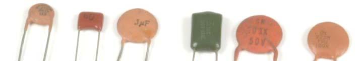
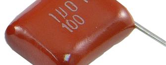
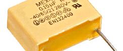
Capacitor ( 電容 ) : C. unit: Farad (F)
|
|
|
- Christal Price
- 5 years ago
- Views:
Transcription
1 Capacitor ( 電容 ) : C unit: Farad (F) 1
2 A C = ε A d ε : dielectric constant t A : area d : distance 2

3 3
4 4
5 4 104 = pf = 0.1 μf = pf = μf 202 = Ω = 2k Ω = Ω = 100k Ω 5
6 6

7 7
8 8


9 9
10 10
11 Q (charge) = C (capacitance) V (voltage) I (current) = dq dt -6 μ = 10-9 n=10 p =
12 Example 1: Direct Current (DC) V C V = 120 volts C = 25 pf Q = CV -12 Q = 120 x ( 25 x 10 ) -9 = 3 x 10 coulomb 12
13 Capacitors in series V1 V2 V3 Vn C1 C2 C3 Q Q Q Q1 Q2 Q3 Cn Q Qn Ce E E 13
14 Q Q Q Q3 Q E = = V1+ V2 + V Vn = C C C C C e n Q = Q = Q = = Q = Q n Q Q Q Q Q E = = C C C C C e n = C C C C C e n 14
15 Capacitors in parallel V1 V2 V3 Vn E C1 C2 C3 Cn Q Q Q Q Q1 Q2 Q3 Qn E Ce 15
16 V1 = V2 = V3 =... = Vn = E EC = Q = Q + Q + Q Q = V C + V C + V C V C e n n n EC = EC + EC + EC + + EC e n C = C + C + C + + C e n 16
17 Example 2: Direct Current (DC) and charging + V R _ R V C + _ V C 17
18 Example 2: Direct Current (DC) and charging ir + V R _ 0 = V VR VC V R C + _ ic V C ir = ic = i(t) i 18
19 Example 2: Direct Current (DC) and charging ir + V R _ 0 = V VR VC V R C + _ ic V C ir = ic = i(t) V VR = ir R ir Q(t) = C VC(t) 19
20 VR + VC = V Q ir R + = V C Q RQ + = V C Q Q + = RC V R 20
21 VR + VC = V Q ir R + = V C y + ay = b -at y(t) = c1e + c2 Q RQ + = V C Q Q + = RC V R 21
22 VR + VC = V Q ir R + = V C y + ay = b -at y(t) = c1e + c2 Q If Q(t=0) = 0 RQ + = V C -t/rc Then, Q(t) = VC(1- e ) Q V Q + = V RC R i(t) = Q (t) = e -t/rc R 22
23 Question: If R = 1000, C = , V = 5, What are V(t) and i(t) at t = 0, τ, and 5τ? 23
24 clf; clear; close all; v = 5; r = 1000; c = ; tau = r * c; time = ones(1000,1); voltage = time; current = time; figure(1) subplot(2,1,1); t(21 1) plot(time/tau,voltage/v,'color','r','linewidth',2); ylim([ ]) title('voltage'); subplot(2,1,2);, plot(time/tau,current/(v/r),'color','g','linewidth',2); ylim([ ]) title('current'); end for i = 1:1:1000 time(i) = i*tau/100; voltage(i) = v*(1-exp(-time(i)/tau)); ( (i)/t )) current(i) = v/r*(exp(-time(i)/tau)); end 24

 t")

25 t t V solution : VC () t = V 1 e τ, i() t = e τ, where RC R τ = V V R τ τ 25


26 26
27 Michael Faraday, FRS (September 22, 1791 August 25, 1867) was an English chemist and physicist who contributed to the fields of electromagnetism and electrochemistry. From: 27
28 Faraday studied the magnetic field around a conductor carrying a DC electric current, and established the basis for the magnetic field concept in physics. He discovered electromagnetic induction, diamagnetism and electrolysis. He established that magnetism could affect rays of light and that there was an underlying relationship between the two phenomena. His inventions of electromagnetic rotary devices formed the foundation of electric motor technology, and it was largely due to his efforts that electricity became viable for use in technology. From: 28
29 Although Faraday received little formal education and knew little of higher mathematics, such as calculus, he was one of the most influential scientists in history. Some historians of science refer to him as the best experimentalist in the history of science. The SI unit of capacitance, the farad, is named after him, as is the Faraday constant, the charge on a mole of electrons (about 96,485 coulombs). Faraday's law of induction states that a magnetic field changing in time creates a proportional electromotive force. From: 29
30 The Royal Institution Christmas Lectures have been held in London annually since They serve as a forum for presenting complex scientific issues to young people p in an informative and entertaining manner. In the mid 1820s Michael Faraday, a former Director of fthe Royal Institution, initiated the first Christmas Lecture series at a time when organised education for young people was scarce. He presented a total of 19 series, establishing an exciting new venture of teaching science to young people that was eventually copied by other institutions internationally. The Christmas Lectures have continued annually since this time, stopping only during World War II. From: 30
31 Michael Faraday, nineteenth century scientist and electrician, shown delivering the British Royal Institution's Christmas Lecture for Juveniles during the Institution's Christmas break in From: 31
32 Example 3: Alternating Current (AC) A ic E = Vm sin(ωt) ~ C V C i 32
33 Example 3: Alternating Current (AC) i A ic E = Vm sin(ωt) ~ C + _ V C i vc(t) = E = Vm sin(ωt) 33
34 VC(t) = E = Vm sin(ωt) q(t) = C VC(t) dq(t) dvc(t) d ic(t) = = C = C [ Vm sin(ω t) ] dt dt dt π = Vm ω C cos(ω t) = Vm ω C sin(ω t + ) 2 34
35 VC(t) = E = Vm sin(ωt) π π ic(t) = Vm ω C sin(ω t + ) = Im sin(ω t + ) 2 2 here Im = Vm ω C The capacitive reactance is defined as: XC Vm 1 1 XC = = = Im ω C (2πf) C 35
36 π VC(t) = E = Vm sin(ωt), ic(t) = Vm ω C sin(ω t + ) 2 Question: E = 10 sin( 200π t) C = 2000 μ F Please calculate: i(t) and Xc 36
37 π ic(t) = Vm ω C sin(ω t + ) 2 π = 10 * (200π) * (0.002) sin(ω t + ) 2 π = sin(ω t + ) Xc = = ω C (2πf) C = Ω 37
38 π VC(t) = E = Vm V sin(ωt), ic(t) = Vm ω Csin(ω t+ ) 2 ωt 38
39 vm = 10; w = 200*pi; c = 0.002; cycle = 2; dt = cycle*(2*pi)/w; time = ones(1000,1); voltage = time; current = time; end for i = 1:1:1000 time(i) = i*dt/1000; voltage(i) = (vm)*sin(w*time(i)); current(i) = (vm*w*c)*cos(w*time(i)); end figure(1) plot(time*w,voltage,'color','r','linewidth',2); hold on; plot(time*w,current,'color','g','linewidth',2); legend('v(t)', 'i(t)'); set(gca,'xtick',0:pi:4*pi), p set(gca,'xticklabel',{'0','pi','2pi','3pi','4pi'}) xlim([0 4*pi]) 39
40 VC(t) = Vm sin(ωt) π ic(t) = Vm ω C sin(ω t + ) 2 = Vm ω C sin(ω t + θ ) 在電容器上, 電流波形領先電壓波形 π/2 ( 相位 )=+θ θ = π/2 40
Gauss s Law. Johann Carl Friedrich Gauss
 Gauss s Law Johann Carl Friedrich Gauss 1777-1855 Mathematics and physics: including number theory, analysis, differential geometry, geodesy, electricity, magnetism, astronomy and optics. y = Be cx 2 First,
Introduction to AC Circuits (Capacitors and Inductors)
") Introduction to AC Circuits (Capacitors and Inductors) Amin Electronics and Electrical Communications Engineering Department (EECE) Cairo University elc.n102.eng@gmail.com http://scholar.cu.edu.eg/refky/
Introduction to AC Circuits (Capacitors and Inductors) Amin Electronics and Electrical Communications Engineering Department (EECE) Cairo University elc.n102.eng@gmail.com http://scholar.cu.edu.eg/refky/
ECE2262 Electric Circuits. Chapter 6: Capacitance and Inductance
 ECE2262 Electric Circuits Chapter 6: Capacitance and Inductance Capacitors Inductors Capacitor and Inductor Combinations Op-Amp Integrator and Op-Amp Differentiator 1 CAPACITANCE AND INDUCTANCE Introduces
Chapter 33. Alternating Current Circuits
 Chapter 33 Alternating Current Circuits 1 Capacitor Resistor + Q = C V = I R R I + + Inductance d I Vab = L dt AC power source The AC power source provides an alternative voltage, Notation - Lower case
Energy Storage Elements: Capacitors and Inductors
 CHAPTER 6 Energy Storage Elements: Capacitors and Inductors To this point in our study of electronic circuits, time has not been important. The analysis and designs we have performed so far have been static,
Inductance, Inductors, RL Circuits & RC Circuits, LC, and RLC Circuits
 Inductance, Inductors, RL Circuits & RC Circuits, LC, and RLC Circuits Self-inductance A time-varying current in a circuit produces an induced emf opposing the emf that initially set up the timevarying
EM Oscillations. David J. Starling Penn State Hazleton PHYS 212
 I ve got an oscillating fan at my house. The fan goes back and forth. It looks like the fan is saying No. So I like to ask it questions that a fan would say no to. Do you keep my hair in place? Do you
ECE2262 Electric Circuits. Chapter 6: Capacitance and Inductance
 ECE2262 Electric Circuits Chapter 6: Capacitance and Inductance Capacitors Inductors Capacitor and Inductor Combinations 1 CAPACITANCE AND INDUCTANCE Introduces two passive, energy storing devices: Capacitors
REACTANCE. By: Enzo Paterno Date: 03/2013
 REACTANCE REACTANCE By: Enzo Paterno Date: 03/2013 5/2007 Enzo Paterno 1 RESISTANCE - R i R (t R A resistor for all practical purposes is unaffected by the frequency of the applied sinusoidal voltage or
Name:... Section:... Physics 208 Quiz 8. April 11, 2008; due April 18, 2008
 Name:... Section:... Problem 1 (6 Points) Physics 8 Quiz 8 April 11, 8; due April 18, 8 Consider the AC circuit consisting of an AC voltage in series with a coil of self-inductance,, and a capacitor of
Review of DC Electric Circuit. DC Electric Circuits Examples (source:
 Review of DC Electric Circuit DC Electric Circuits Examples (source: http://hyperphysics.phyastr.gsu.edu/hbase/electric/dcex.html) 1 Review - DC Electric Circuit Multisim Circuit Simulation DC Circuit
Chapter 31: AC Circuits
 hapter 31: A ircuits A urrents and Voltages In this chapter, we discuss the behior of circuits driven by a source of A. Recall that A means, literally, alternating current. An alternating current is a
Alternating Current. Symbol for A.C. source. A.C.
 Alternating Current Kirchoff s rules for loops and junctions may be used to analyze complicated circuits such as the one below, powered by an alternating current (A.C.) source. But the analysis can quickly
EECE251. Circuit Analysis I. Set 4: Capacitors, Inductors, and First-Order Linear Circuits
 EECE25 Circuit Analysis I Set 4: Capacitors, Inductors, and First-Order Linear Circuits Shahriar Mirabbasi Department of Electrical and Computer Engineering University of British Columbia shahriar@ece.ubc.ca
Chapter 24: Capacitance and Dielectrics
 Chapter 24: Capacitance and Dielectrics When you compress/stretch a spring, we are storing potential energy This is the mechanical method to store energy It is also possible to store electric energy as
Basics of Network Theory (Part-I)
") Basics of Network Theory (Part-I) 1. One coulomb charge is equal to the charge on (a) 6.24 x 10 18 electrons (b) 6.24 x 10 24 electrons (c) 6.24 x 10 18 atoms (d) none of the above 2. The correct relation
Basics of Network Theory (Part-I) 1. One coulomb charge is equal to the charge on (a) 6.24 x 10 18 electrons (b) 6.24 x 10 24 electrons (c) 6.24 x 10 18 atoms (d) none of the above 2. The correct relation
Chapter 24: Capacitance and Dielectrics
 Chapter 24: Capacitance and Dielectrics When you compress/stretch a spring, we are storing potential energy This is the mechanical method to store energy It is also possible to store electric energy as
Physics 219 Question 1 January
 Lecture 6-16 Physics 219 Question 1 January 30. 2012. A (non-ideal) battery of emf 1.5 V and internal resistance 5 Ω is connected to a light bulb of resistance 50 Ω. How much power is delivered to the
Chapter 24 Capacitance and Dielectrics
 Chapter 24 Capacitance and Dielectrics 1 Capacitors and Capacitance A capacitor is a device that stores electric potential energy and electric charge. The simplest construction of a capacitor is two parallel
Self-Inductance. Φ i. Self-induction. = (if flux Φ 1 through 1 loop. Tm Vs A A. Lecture 11-1
 Lecture - Self-Inductance As current i through coil increases, magnetic flux through itself increases. This in turn induces back emf in the coil itself When current i is decreasing, emf is induced again
Chapter 32. Inductance
 Chapter 32 Inductance Joseph Henry 1797 1878 American physicist First director of the Smithsonian Improved design of electromagnet Constructed one of the first motors Discovered self-inductance Unit of
Self-inductance A time-varying current in a circuit produces an induced emf opposing the emf that initially set up the time-varying current.
 Inductance Self-inductance A time-varying current in a circuit produces an induced emf opposing the emf that initially set up the time-varying current. Basis of the electrical circuit element called an
Circuits. David J. Starling Penn State Hazleton PHYS 212
 Invention is the most important product of man s creative brain. The ultimate purpose is the complete mastery of mind over the material world, the harnessing of human nature to human needs. - Nikola Tesla
Louisiana State University Physics 2102, Exam 2, March 5th, 2009.
 PRINT Your Name: Instructor: Louisiana State University Physics 2102, Exam 2, March 5th, 2009. Please be sure to PRINT your name and class instructor above. The test consists of 4 questions (multiple choice),
Coulomb s constant k = 9x10 9 N m 2 /C 2
 1 Part 2: Electric Potential 2.1: Potential (Voltage) & Potential Energy q 2 Potential Energy of Point Charges Symbol U mks units [Joules = J] q 1 r Two point charges share an electric potential energy
Part 4: Electromagnetism. 4.1: Induction. A. Faraday's Law. The magnetic flux through a loop of wire is
 1 Part 4: Electromagnetism 4.1: Induction A. Faraday's Law The magnetic flux through a loop of wire is Φ = BA cos θ B A B = magnetic field penetrating loop [T] A = area of loop [m 2 ] = angle between field
ENGR 2405 Chapter 6. Capacitors And Inductors
 ENGR 2405 Chapter 6 Capacitors And Inductors Overview This chapter will introduce two new linear circuit elements: The capacitor The inductor Unlike resistors, these elements do not dissipate energy They
Driven RLC Circuits Challenge Problem Solutions
 Driven LC Circuits Challenge Problem Solutions Problem : Using the same circuit as in problem 6, only this time leaving the function generator on and driving below resonance, which in the following pairs
Louisiana State University Physics 2102, Exam 3 April 2nd, 2009.
 PRINT Your Name: Instructor: Louisiana State University Physics 2102, Exam 3 April 2nd, 2009. Please be sure to PRINT your name and class instructor above. The test consists of 4 questions (multiple choice),
AC vs. DC Circuits. Constant voltage circuits. The voltage from an outlet is alternating voltage
 Circuits AC vs. DC Circuits Constant voltage circuits Typically referred to as direct current or DC Computers, logic circuits, and battery operated devices are examples of DC circuits The voltage from
Physics 115. General Physics II. Session 24 Circuits Series and parallel R Meters Kirchoff s Rules
 Physics 115 General Physics II Session 24 Circuits Series and parallel R Meters Kirchoff s Rules R. J. Wilkes Email: phy115a@u.washington.edu Home page: http://courses.washington.edu/phy115a/ 5/15/14 Phys
Oscillations and Electromagnetic Waves. March 30, 2014 Chapter 31 1
 Oscillations and Electromagnetic Waves March 30, 2014 Chapter 31 1 Three Polarizers! Consider the case of unpolarized light with intensity I 0 incident on three polarizers! The first polarizer has a polarizing
Chapter 21: RLC Circuits. PHY2054: Chapter 21 1
 Chapter 21: RC Circuits PHY2054: Chapter 21 1 Voltage and Current in RC Circuits AC emf source: driving frequency f ε = ε sinωt ω = 2π f m If circuit contains only R + emf source, current is simple ε ε
Look over. examples 1, 2, 3, 5, 6. Look over. Chapter 25 section 1-8. Chapter 19 section 5 Example 10, 11
 PHYS Look over hapter 5 section -8 examples,, 3, 5, 6 PHYS Look over hapter 7 section 7-9 Examples 8, hapter 9 section 5 Example 0, Things to Know ) How to find the charge on a apacitor. ) How to find
Solutions to these tests are available online in some places (but not all explanations are good)...
...") The Physics GRE Sample test put out by ETS https://www.ets.org/s/gre/pdf/practice_book_physics.pdf OSU physics website has lots of tips, and 4 additional tests http://www.physics.ohiostate.edu/undergrad/ugs_gre.php
The Physics GRE Sample test put out by ETS https://www.ets.org/s/gre/pdf/practice_book_physics.pdf OSU physics website has lots of tips, and 4 additional tests http://www.physics.ohiostate.edu/undergrad/ugs_gre.php
Capacitance and Dielectrics
 Slide 1 / 39 Capacitance and Dielectrics 2011 by Bryan Pflueger Capacitors Slide 2 / 39 A capacitor is any two conductors seperated by an insulator, such as air or another material. Each conductor has
1 Phasors and Alternating Currents
 Physics 4 Chapter : Alternating Current 0/5 Phasors and Alternating Currents alternating current: current that varies sinusoidally with time ac source: any device that supplies a sinusoidally varying potential
Chapter 24 Capacitance and Dielectrics
 Chapter 24 Capacitance and Dielectrics 1 Capacitors and Capacitance A capacitor is a device that stores electric potential energy and electric charge. The simplest construction of a capacitor is two parallel
EXPERIMENT 07 TO STUDY DC RC CIRCUIT AND TRANSIENT PHENOMENA
 EXPERIMENT 07 TO STUDY DC RC CIRCUIT AND TRANSIENT PHENOMENA DISCUSSION The capacitor is a element which stores electric energy by charging the charge on it. Bear in mind that the charge on a capacitor
Chapter 21 Lecture Notes
 Chapter 21 Lecture Notes Physics 2424 - Strauss Formulas: Φ = BA cosφ E = -N Φ/ t Faraday s Law E = Bvl E = NABω sinωt M = (N 2 Φ 2 )/I 1 E 2 = -M I 1 / t L = NΦ/I E = -L I/ t L = µ 0 n 2 A l Energy =
Potential from a distribution of charges = 1
 Lecture 7 Potential from a distribution of charges V = 1 4 0 X Smooth distribution i q i r i V = 1 4 0 X i q i r i = 1 4 0 Z r dv Calculating the electric potential from a group of point charges is usually
Alternating Current Circuits. Home Work Solutions
 Chapter 21 Alternating Current Circuits. Home Work s 21.1 Problem 21.11 What is the time constant of the circuit in Figure (21.19). 10 Ω 10 Ω 5.0 Ω 2.0µF 2.0µF 2.0µF 3.0µF Figure 21.19: Given: The circuit
CIRCUIT ELEMENT: CAPACITOR
 CIRCUIT ELEMENT: CAPACITOR PROF. SIRIPONG POTISUK ELEC 308 Types of Circuit Elements Two broad types of circuit elements Ati Active elements -capable of generating electric energy from nonelectric energy
The Basic Capacitor. Water Tower / Capacitor Analogy. "Partnering With Our Clients for Combined Success"
 CAPACITOR BASICS I How s Work The Basic A capacitor is an electrical device which serves to store up electrical energy for release at a predetermined time. In its most basic form, it is comprised of three
Inductance, RL and RLC Circuits
 Inductance, RL and RLC Circuits Inductance Temporarily storage of energy by the magnetic field When the switch is closed, the current does not immediately reach its maximum value. Faraday s law of electromagnetic
Physics 4B Chapter 31: Electromagnetic Oscillations and Alternating Current
 Physics 4B Chapter 31: Electromagnetic Oscillations and Alternating Current People of mediocre ability sometimes achieve outstanding success because they don't know when to quit. Most men succeed because
Electrical Circuits (2)
") Electrical Circuits (2) Lecture 7 Transient Analysis Dr.Eng. Basem ElHalawany Extra Reference for this Lecture Chapter 16 Schaum's Outline Of Theory And Problems Of Electric Circuits https://archive.org/details/theoryandproblemsofelectriccircuits
Electrical Circuits (2) Lecture 7 Transient Analysis Dr.Eng. Basem ElHalawany Extra Reference for this Lecture Chapter 16 Schaum's Outline Of Theory And Problems Of Electric Circuits https://archive.org/details/theoryandproblemsofelectriccircuits
Capacitance and capacitors. Dr. Loai Afana
 apacitance and capacitors apacitors apacitors are devices that store energy in an electric field. apacitors are used in many every-day applications Heart defibrillators amera flash units apacitors are
Chapter 27. Circuits
 Chapter 27 Circuits 1 1. Pumping Chagres We need to establish a potential difference between the ends of a device to make charge carriers follow through the device. To generate a steady flow of charges,
A capacitor is a device that stores electric charge (memory devices). A capacitor is a device that stores energy E = Q2 2C = CV 2
. A capacitor is a device that stores energy E = Q2 2C = CV 2") Capacitance: Lecture 2: Resistors and Capacitors Capacitance (C) is defined as the ratio of charge (Q) to voltage (V) on an object: C = Q/V = Coulombs/Volt = Farad Capacitance of an object depends on geometry
Capacitance: Lecture 2: Resistors and Capacitors Capacitance (C) is defined as the ratio of charge (Q) to voltage (V) on an object: C = Q/V = Coulombs/Volt = Farad Capacitance of an object depends on geometry
EELE 3332 Electromagnetic II Chapter 9. Maxwell s Equations. Islamic University of Gaza Electrical Engineering Department Dr.
 EELE 3332 Electromagnetic II Chapter 9 Maxwell s Equations Islamic University of Gaza Electrical Engineering Department Dr. Talal Skaik 2013 1 Review Electrostatics and Magnetostatics Electrostatic Fields
BME/ISE 3511 Bioelectronics - Test Six Course Notes Fall 2016
 BME/ISE 35 Bioelectronics - Test Six ourse Notes Fall 06 Alternating urrent apacitive & Inductive Reactance and omplex Impedance R & R ircuit Analyses (D Transients, Time onstants, Steady State) Electrical
INDUCTANCE Self Inductance
 NDUTANE 3. Self nductance onsider the circuit shown in the Figure. When the switch is closed the current, and so the magnetic field, through the circuit increases from zero to a specific value. The increasing
Name: Lab Partner: Section:
 Chapter 6 Capacitors and RC Circuits Name: Lab Partner: Section: 6.1 Purpose The purpose of this experiment is to investigate the physics of capacitors in circuits. The charging and discharging of a capacitor
CHAPTER FOUR MUTUAL INDUCTANCE
 CHAPTER FOUR MUTUAL INDUCTANCE 4.1 Inductance 4.2 Capacitance 4.3 Serial-Parallel Combination 4.4 Mutual Inductance 4.1 Inductance Inductance (L in Henry is the circuit parameter used to describe an inductor.
Lecture 05 Power in AC circuit
 CA2627 Building Science Lecture 05 Power in AC circuit Instructor: Jiayu Chen Ph.D. Announcement 1. Makeup Midterm 2. Midterm grade Grade 25 20 15 10 5 0 10 15 20 25 30 35 40 Grade Jiayu Chen, Ph.D. 2
CS 436 HCI Technology Basic Electricity/Electronics Review
 CS 436 HCI Technology Basic Electricity/Electronics Review *Copyright 1997-2008, Perry R. Cook, Princeton University August 27, 2008 1 Basic Quantities and Units 1.1 Charge Number of electrons or units
The Basic Capacitor. Dielectric. Conductors
 Chapter 9 The Basic Capacitor Capacitors are one of the fundamental passive components. In its most basic form, it is composed of two conductive plates separated by an insulating dielectric. The ability
Chapter 32. Inductance
 Chapter 32 Inductance Inductance Self-inductance A time-varying current in a circuit produces an induced emf opposing the emf that initially set up the time-varying current. Basis of the electrical circuit
a + b Time Domain i(τ)dτ.
dτ.") R, C, and L Elements and their v and i relationships We deal with three essential elements in circuit analysis: Resistance R Capacitance C Inductance L Their v and i relationships are summarized below.
R, C, and L Elements and their v and i relationships We deal with three essential elements in circuit analysis: Resistance R Capacitance C Inductance L Their v and i relationships are summarized below.
Chapter 17 Lecture Notes
 Chapter 17 Lecture Notes Physics 2424 - Strauss Formulas: qv = U E W = Fd(cosθ) W = - U E V = Ed V = kq/r. Q = CV C = κε 0 A/d κ = E 0 /E E = (1/2)CV 2 Definition of electric potential Definition of Work
Assessment Schedule 2015 Physics: Demonstrate understanding of electrical systems (91526)
") NCEA Level 3 Physics (91526) 2015 page 1 of 6 Assessment Schedule 2015 Physics: Demonstrate understanding of electrical systems (91526) Evidence Q Evidence Achievement Achievement with Merit Achievement
NCEA Level 3 Physics (91526) 2015 page 1 of 6 Assessment Schedule 2015 Physics: Demonstrate understanding of electrical systems (91526) Evidence Q Evidence Achievement Achievement with Merit Achievement
K.K. Gan L3: R-L-C AC Circuits. amplitude. Volts. period. -Vo
 Lecture 3: R-L-C AC Circuits AC (Alternative Current): Most of the time, we are interested in the voltage at a point in the circuit will concentrate on voltages here rather than currents. We encounter
Module 4. Single-phase AC Circuits
 Module 4 Single-phase AC Circuits Lesson 14 Solution of Current in R-L-C Series Circuits In the last lesson, two points were described: 1. How to represent a sinusoidal (ac) quantity, i.e. voltage/current
Lecture 11 - AC Power
 - AC Power 11/17/2015 Reading: Chapter 11 1 Outline Instantaneous power Complex power Average (real) power Reactive power Apparent power Maximum power transfer Power factor correction 2 Power in AC Circuits
3 The non-linear elements
 3.1 Introduction The inductor and the capacitor are the two important passive circuit elements which have the ability to store and deliver finite amount of energy [49]. In an inductor, the energy is stored
Electricity & Optics
 Physics 241 Electricity & Optics Lecture 12 Chapter 25 sec. 6, 26 sec. 1 Fall 217 Semester Professor Koltick Circuits With Capacitors C Q = C V V = Q C + V R C, Q Kirchhoff s Loop Rule: V I R V = V I R
iclicker Quiz a) True b) False
 True b) False") iclicker Quiz (1) I have completed at least 50% of the reading and studyguide assignments associated with the lecture, as indicated on the course schedule. a) True b) False Note on Monday is fee late day
iclicker Quiz (1) I have completed at least 50% of the reading and studyguide assignments associated with the lecture, as indicated on the course schedule. a) True b) False Note on Monday is fee late day
Exam 3 Solutions. The induced EMF (magnitude) is given by Faraday s Law d dt dt The current is given by
 is given by Faraday s Law d dt dt The current is given by") PHY049 Spring 008 Prof. Darin Acosta Prof. Selman Hershfield April 9, 008. A metal rod is forced to move with constant velocity of 60 cm/s [or 90 cm/s] along two parallel metal rails, which are connected
PHY049 Spring 008 Prof. Darin Acosta Prof. Selman Hershfield April 9, 008. A metal rod is forced to move with constant velocity of 60 cm/s [or 90 cm/s] along two parallel metal rails, which are connected
BIOGRAPHY OF MICHAEL FARADAY PART - 1. By SIDDHANT AGNIHOTRI B.Sc (Silver Medalist) M.Sc (Applied Physics) Facebook: sid_educationconnect
 M.Sc (Applied Physics) Facebook: sid_educationconnect") BIOGRAPHY OF MICHAEL FARADAY PART - 1 By SIDDHANT AGNIHOTRI B.Sc (Silver Medalist) M.Sc (Applied Physics) Facebook: sid_educationconnect WHAT WE WILL STUDY? CHILDHOOD STRUGGLE MAKING OF A GREAT SCIENTIST
BIOGRAPHY OF MICHAEL FARADAY PART - 1 By SIDDHANT AGNIHOTRI B.Sc (Silver Medalist) M.Sc (Applied Physics) Facebook: sid_educationconnect WHAT WE WILL STUDY? CHILDHOOD STRUGGLE MAKING OF A GREAT SCIENTIST
Chapter 28. Direct Current Circuits
 Chapter 28 Direct Current Circuits Circuit Analysis Simple electric circuits may contain batteries, resistors, and capacitors in various combinations. For some circuits, analysis may consist of combining
Chapter 6 Objectives
 hapter 6 Engr8 ircuit Analysis Dr urtis Nelson hapter 6 Objectives Understand relationships between voltage, current, power, and energy in inductors and capacitors; Know that current must be continuous
Physics 115. AC: RL vs RC circuits Phase relationships RLC circuits. General Physics II. Session 33
 Session 33 Physics 115 General Physics II AC: RL vs RC circuits Phase relationships RLC circuits R. J. Wilkes Email: phy115a@u.washington.edu Home page: http://courses.washington.edu/phy115a/ 6/2/14 1
EELE 3332 Electromagnetic II Chapter 9. Maxwell s Equations. Islamic University of Gaza Electrical Engineering Department Dr.
 EELE 3332 Electromagnetic II Chapter 9 Maxwell s Equations Islamic University of Gaza Electrical Engineering Department Dr. Talal Skaik 2012 1 Review Electrostatics and Magnetostatics Electrostatic Fields
RC Circuits (32.9) Neil Alberding (SFU Physics) Physics 121: Optics, Electricity & Magnetism Spring / 1
 Neil Alberding (SFU Physics) Physics 121: Optics, Electricity & Magnetism Spring / 1") (32.9) We have only been discussing DC circuits so far. However, using a capacitor we can create an RC circuit. In this example, a capacitor is charged but the switch is open, meaning no current flows.
(32.9) We have only been discussing DC circuits so far. However, using a capacitor we can create an RC circuit. In this example, a capacitor is charged but the switch is open, meaning no current flows.
PESIT Bangalore South Campus Hosur road, 1km before Electronic City, Bengaluru -100 Department of Electronics & Communication Engineering
 QUESTION PAPER INTERNAL ASSESSMENT TEST 2 Date : /10/2016 Marks: 0 Subject & Code: BASIC ELECTRICAL ENGINEERING -15ELE15 Sec : F,G,H,I,J,K Name of faculty : Dhanashree Bhate, Hema B, Prashanth V Time :
20. Alternating Currents
 University of hode sland DigitalCommons@U PHY 204: Elementary Physics Physics Course Materials 2015 20. lternating Currents Gerhard Müller University of hode sland, gmuller@uri.edu Creative Commons License
Prof. Anyes Taffard. Physics 120/220. Voltage Divider Capacitor RC circuits
 Prof. Anyes Taffard Physics 120/220 Voltage Divider Capacitor RC circuits Voltage Divider The figure is called a voltage divider. It s one of the most useful and important circuit elements we will encounter.
Experiment Guide for RC Circuits
 Guide-P1 Experiment Guide for RC Circuits I. Introduction 1. Capacitors A capacitor is a passive electronic component that stores energy in the form of an electrostatic field. The unit of capacitance is
SUMMARY Phys 2523 (University Physics II) Compiled by Prof. Erickson. F e (r )=q E(r ) dq r 2 ˆr = k e E = V. V (r )=k e r = k q i. r i r.
 Compiled by Prof. Erickson. F e (r )=q E(r ) dq r 2 ˆr = k e E = V. V (r )=k e r = k q i. r i r.") SUMMARY Phys 53 (University Physics II) Compiled by Prof. Erickson q 1 q Coulomb s Law: F 1 = k e r ˆr where k e = 1 4π =8.9875 10 9 N m /C, and =8.85 10 1 C /(N m )isthepermittivity of free space. Generally,
SUMMARY Phys 53 (University Physics II) Compiled by Prof. Erickson q 1 q Coulomb s Law: F 1 = k e r ˆr where k e = 1 4π =8.9875 10 9 N m /C, and =8.85 10 1 C /(N m )isthepermittivity of free space. Generally,
Principles of Physics II
 Principles of Physics II J. M. Veal, Ph. D. version 18.05.4 Contents 1 Fluid Mechanics 3 1.1 Fluid pressure............................ 3 1. Buoyancy.............................. 3 1.3 Fluid flow..............................
Capacitor. Capacitor (Cont d)
") 1 2 1 Capacitor Capacitor is a passive two-terminal component storing the energy in an electric field charged by the voltage across the dielectric. Fixed Polarized Variable Capacitance is the ratio of
1 2 1 Capacitor Capacitor is a passive two-terminal component storing the energy in an electric field charged by the voltage across the dielectric. Fixed Polarized Variable Capacitance is the ratio of
Lecture 35: FRI 17 APR Electrical Oscillations, LC Circuits, Alternating Current I
 Physics 3 Jonathan Dowling Lecture 35: FRI 7 APR Electrical Oscillations, LC Circuits, Alternating Current I Nikolai Tesla What are we going to learn? A road map Electric charge è Electric force on other
ECE 241L Fundamentals of Electrical Engineering. Experiment 6 AC Circuits
 ECE 241L Fundamentals of Electrical Engineering Experiment 6 AC Circuits A. Objectives: Objectives: I. Calculate amplitude and phase angles of a-c voltages and impedances II. Calculate the reactance and
University of TN Chattanooga Physics 1040L 8/18/2012 PHYSICS 1040L LAB LAB 4: R.C. TIME CONSTANT LAB
 PHYSICS 1040L LAB LAB 4: R.C. TIME CONSTANT LAB OBJECT: To study the discharging of a capacitor and determine the time constant for a simple circuit. APPARATUS: Capacitor (about 24 μf), two resistors (about
Physics 2B Winter 2012 Final Exam Practice
 Physics 2B Winter 2012 Final Exam Practice 1) When the distance between two charges is increased, the force between the charges A) increases directly with the square of the distance. B) increases directly
Source-Free RC Circuit
 First Order Circuits Source-Free RC Circuit Initial charge on capacitor q = Cv(0) so that voltage at time 0 is v(0). What is v(t)? Prof Carruthers (ECE @ BU) EK307 Notes Summer 2018 150 / 264 First Order
This work is licensed under a Creative Commons Attribution-Noncommercial-Share Alike 4.0 License.
 University of Rhode Island DigitalCommons@URI PHY 204: Elementary Physics II Physics Course Materials 2015 11. RC Circuits Gerhard Müller University of Rhode Island, gmuller@uri.edu Creative Commons License
Lecture 27: FRI 20 MAR
 Physics 2102 Jonathan Dowling Lecture 27: FRI 20 MAR Ch.30.7 9 Inductors & Inductance Nikolai Tesla Inductors: Solenoids Inductors are with respect to the magnetic field what capacitors are with respect
Learnabout Electronics - AC Theory
 Learnabout Electronics - AC Theory Facts & Formulae for AC Theory www.learnabout-electronics.org Contents AC Wave Values... 2 Capacitance... 2 Charge on a Capacitor... 2 Total Capacitance... 2 Inductance...
Note 11: Alternating Current (AC) Circuits
 Circuits") Note 11: Alternating Current (AC) Circuits V R No phase difference between the voltage difference and the current and max For alternating voltage Vmax sin t, the resistor current is ir sin t. the instantaneous
Note 11: Alternating Current (AC) Circuits V R No phase difference between the voltage difference and the current and max For alternating voltage Vmax sin t, the resistor current is ir sin t. the instantaneous
Capacitance, Resistance, DC Circuits
 This test covers capacitance, electrical current, resistance, emf, electrical power, Ohm s Law, Kirchhoff s Rules, and RC Circuits, with some problems requiring a knowledge of basic calculus. Part I. Multiple
Induction_P1. 1. [1 mark]
![Induction_P1. 1. [1 mark]](/thumbs/88/115570773.jpg "Induction_P1. 1. [1 mark]") Induction_P1 1. [1 mark] Two identical circular coils are placed one below the other so that their planes are both horizontal. The top coil is connected to a cell and a switch. The switch is closed and
Induction_P1 1. [1 mark] Two identical circular coils are placed one below the other so that their planes are both horizontal. The top coil is connected to a cell and a switch. The switch is closed and
Chapter 31: RLC Circuits. PHY2049: Chapter 31 1
 Chapter 31: RLC Circuits PHY049: Chapter 31 1 LC Oscillations Conservation of energy Topics Dampe oscillations in RLC circuits Energy loss AC current RMS quantities Force oscillations Resistance, reactance,
Physics for Scientists & Engineers 2
 Electromagnetic Oscillations Physics for Scientists & Engineers Spring Semester 005 Lecture 8! We have been working with circuits that have a constant current a current that increases to a constant current
Module 25: Outline Resonance & Resonance Driven & LRC Circuits Circuits 2
 Module 25: Driven RLC Circuits 1 Module 25: Outline Resonance & Driven LRC Circuits 2 Driven Oscillations: Resonance 3 Mass on a Spring: Simple Harmonic Motion A Second Look 4 Mass on a Spring (1) (2)
Chapter 21 Magnetic Induction Lecture 12
 Chapter 21 Magnetic Induction Lecture 12 21.1 Why is it called Electromagnetism? 21.2 Magnetic Flux and Faraday s Law 21.3 Lenz s Law and Work-Energy Principles 21.4 Inductance 21.5 RL Circuits 21.6 Energy
Calculus Relationships in AP Physics C: Electricity and Magnetism
 C: Electricity This chapter focuses on some of the quantitative skills that are important in your C: Mechanics course. These are not all of the skills that you will learn, practice, and apply during the
FINAL EXAM - Physics Patel SPRING 1998 FORM CODE - A
 FINAL EXAM - Physics 202 - Patel SPRING 1998 FORM CODE - A Be sure to fill in your student number and FORM letter (A, B, C, D, E) on your answer sheet. If you forget to include this information, your Exam
Electromagnetic Induction! March 11, 2014 Chapter 29 1
 Electromagnetic Induction! March 11, 2014 Chapter 29 1 Notes! Exam 4 next Tuesday Covers Chapters 27, 28, 29 in the book Magnetism, Magnetic Fields, Electromagnetic Induction Material from the week before