Electrical Circuits (2)
|
|
|
- Wesley Lloyd
- 5 years ago
- Views:
Transcription
")


1 Electrical Circuits (2) Lecture 7 Transient Analysis Dr.Eng. Basem ElHalawany
2 Extra Reference for this Lecture Chapter 16 Schaum's Outline Of Theory And Problems Of Electric Circuits Electrical Circuits (2) - Basem ElHalawany 2
3 Circuits Transient Response When a circuit is switched from one condition to another either by a change in the applied voltage or a change in one of the circuit elements, there is a transitional period during which the branch currents and voltage drops change from their former values to new ones After this transition interval called the transient, the circuit is said to be in the steady state. So far all the calculations we have performed have led to a Steady State solution to a problem i.e. the final value after everything has settled down. Transient analysis: study of circuit behavior in transition phase. Electric Circuits (2) - Basem ElHalawany 3
4 The steady state values can be determined using circuit laws and complex number theory. The transient is more difficult as it involves differential equations. a n n d x( t) n dt General solution to the differential equation: x( t) x p ( t) xc ( t) x p (t) x c (t) Complementary solution (or natural Particular integral solution (or forced response particular to a given source/excitation) Represent the steady-state solution which is the solution to the above nonhomogeneous equation a a n n n1 d x( t) 1... a0x( t) f ( t) n1 dt n d x( t) n dt response) Represent the transient part of the solution, which is the solution of the next homogeneous equation: a n n1 d x( t) 1... a0x( t) n1 dt Electrical Circuits (2) - Basem ElHalawany 4 0
5 First-Order and Second-Order Circuits First-order circuits contain only a single capacitor or inductor Second-order circuits contain both a capacitor and an inductor Differential equations Solutions Two techniques for transient analysis that we will learn: Differential equation approach. Laplace Transform approach. Laplace transform method is a much simpler method for transient analysis but we will see both :P Electrical Circuits (2) - Basem ElHalawany 5
6 First-Order RC Transient Step-Response o Assume the switch S is closed at t = 0 o Apply KVL to the series RC circuit shown: o Differentiating both sides which gives: o The solution to this homogeneous equation consists of only the complementary function since the particular solution is zero. o To find the complementary Solution, solve the auxiliary equation: 1 0 m RC The complementary Solution is : 1 1 m RC RC Time constant mt i Ae i A t e Electrical Circuits (2) - Basem ElHalawany 6
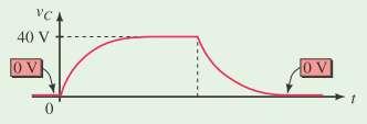
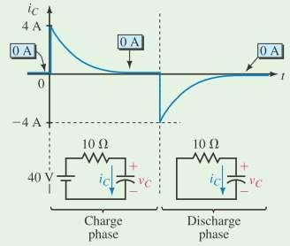
7 First-Order RC Transient Step-Response 7 o To determine the constant A we note that : Where Vc (0) = 0 o Now substituting the value of io into current equation o We obtain A = V/R at t = 0. has the form of an exponential decay starting from the transient value to the final steady-state value of 0 ampere in 5 time-constants
8 First-Order RC Transient Step-Response The voltage across the resistor is: The voltage across the capacitor is: 8
9 Time-Constant Transient-response is almost finished after 5τ 1. Exponential-Decay t τ 2τ 3τ 4τ 5τ i(t) 2. Exponential-Rise V V 0.05 V V V R R R R R t τ 2τ 3τ 4τ 5τ VC(t) V V 0.95 V 0.98 V 0.99 V 9
10 First-Order RC Transient (Discharge) 10 The series RC circuit shown in Figure has the switch in position 1 for sufficient time to establish the steady state At t = 0, the switch is moved to position 2 o Differentiating both sides which gives: The Solution also is : i Ae mt Ae o Substitute by the initial condition of the current to get the constant A: o Since the capacitor is charged to a voltage V with the polarity shown in the diagram, the initial current is opposite to i; t RC Then A V / R i Then ( V / R) e t RC
11 First-Order RC Transient (Discharge) 11 The decay transient of the current is shown in figure The corresponding transient voltages

12 Examples 12


13 Capacitor with an Initial Voltage 13 Suppose a previously charged capacitor has not been discharged and thus still has voltage on it. Ex: Suppose the capacitor of Figure has 25 volts on it with polarity shown at the time the switch is closed.
14 The switch S is closed at t = 0 Apply KVL to the circuit in figure: First-Order RL Transient Step-Response 14 Rearranging and using D operator notation : This Equation is a first order, linear differential equation 1. Complementary (Transient) Solution R The auxiliary equation is : m 0 L mt 2. Particular (Steady-State) Solution i Ae Ae R t L The steady-state value of the current for DC source is : R L Time constant I ss V R
15 First-Order RL Transient Step-Response 15 The total solution is: Since The initial current is zero: i Ae 0 R t L A V R V R The voltage across the resistor is: The voltage across the inductor is:
16 First-Order RL Transient (Discharge) The RL circuit shown in Figure contains an initial current of (V/R) The Switch S is moved to position 2 at t=0 16 The solution is the transient (Complementary) part only. Using the initial condition of the current, we get: The corresponding voltages across the resistance and inductance are
17 Examples Electrical Circuits (2) - Basem ElHalawany 17
18 Examples (b) For the two voltage to be equal: each must be 50 volts since the applied voltage is 100, Electrical Circuits (2) - Basem ElHalawany 18
EE292: Fundamentals of ECE
 EE292: Fundamentals of ECE Fall 2012 TTh 10:00-11:15 SEB 1242 Lecture 14 121011 http://www.ee.unlv.edu/~b1morris/ee292/ 2 Outline Review Steady-State Analysis RC Circuits RL Circuits 3 DC Steady-State
Electric Circuits. Overview. Hani Mehrpouyan,
 Electric Circuits Hani Mehrpouyan, Department of Electrical and Computer Engineering, Lecture 15 (First Order Circuits) Nov 16 th, 2015 Hani Mehrpouyan (hani.mehr@ieee.org) Boise State c 2015 1 1 Overview
To find the step response of an RC circuit
 To find the step response of an RC circuit v( t) v( ) [ v( t) v( )] e tt The time constant = RC The final capacitor voltage v() The initial capacitor voltage v(t ) To find the step response of an RL circuit
Basic RL and RC Circuits R-L TRANSIENTS: STORAGE CYCLE. Engineering Collage Electrical Engineering Dep. Dr. Ibrahim Aljubouri
 st Class Basic RL and RC Circuits The RL circuit with D.C (steady state) The inductor is short time at Calculate the inductor current for circuits shown below. I L E R A I L E R R 3 R R 3 I L I L R 3 R
Chapter 4 Transients. Chapter 4 Transients
 Chapter 4 Transients Chapter 4 Transients 1. Solve first-order RC or RL circuits. 2. Understand the concepts of transient response and steady-state response. 1 3. Relate the transient response of first-order
ECE2262 Electric Circuit
 ECE2262 Electric Circuit Chapter 7: FIRST AND SECOND-ORDER RL AND RC CIRCUITS Response to First-Order RL and RC Circuits Response to Second-Order RL and RC Circuits 1 2 7.1. Introduction 3 4 In dc steady
MODULE I. Transient Response:
 Transient Response: MODULE I The Transient Response (also known as the Natural Response) is the way the circuit responds to energies stored in storage elements, such as capacitors and inductors. If a capacitor
RC Circuits (32.9) Neil Alberding (SFU Physics) Physics 121: Optics, Electricity & Magnetism Spring / 1
 Neil Alberding (SFU Physics) Physics 121: Optics, Electricity & Magnetism Spring / 1") (32.9) We have only been discussing DC circuits so far. However, using a capacitor we can create an RC circuit. In this example, a capacitor is charged but the switch is open, meaning no current flows.
(32.9) We have only been discussing DC circuits so far. However, using a capacitor we can create an RC circuit. In this example, a capacitor is charged but the switch is open, meaning no current flows.
Lecture 39. PHYC 161 Fall 2016
 Lecture 39 PHYC 161 Fall 016 Announcements DO THE ONLINE COURSE EVALUATIONS - response so far is < 8 % Magnetic field energy A resistor is a device in which energy is irrecoverably dissipated. By contrast,
Alternating Current Circuits. Home Work Solutions
 Chapter 21 Alternating Current Circuits. Home Work s 21.1 Problem 21.11 What is the time constant of the circuit in Figure (21.19). 10 Ω 10 Ω 5.0 Ω 2.0µF 2.0µF 2.0µF 3.0µF Figure 21.19: Given: The circuit
Physics 116A Notes Fall 2004
 Physics 116A Notes Fall 2004 David E. Pellett Draft v.0.9 Notes Copyright 2004 David E. Pellett unless stated otherwise. References: Text for course: Fundamentals of Electrical Engineering, second edition,
2005 AP PHYSICS C: ELECTRICITY AND MAGNETISM FREE-RESPONSE QUESTIONS
 2005 AP PHYSICS C: ELECTRICITY AND MAGNETISM In the circuit shown above, resistors 1 and 2 of resistance R 1 and R 2, respectively, and an inductor of inductance L are connected to a battery of emf e and
First-order transient
 EIE209 Basic Electronics First-order transient Contents Inductor and capacitor Simple RC and RL circuits Transient solutions Constitutive relation An electrical element is defined by its relationship between
LAPLACE TRANSFORMATION AND APPLICATIONS. Laplace transformation It s a transformation method used for solving differential equation.
 LAPLACE TRANSFORMATION AND APPLICATIONS Laplace transformation It s a transformation method used for solving differential equation. Advantages The solution of differential equation using LT, progresses
Introduction to AC Circuits (Capacitors and Inductors)
") Introduction to AC Circuits (Capacitors and Inductors) Amin Electronics and Electrical Communications Engineering Department (EECE) Cairo University elc.n102.eng@gmail.com http://scholar.cu.edu.eg/refky/
Introduction to AC Circuits (Capacitors and Inductors) Amin Electronics and Electrical Communications Engineering Department (EECE) Cairo University elc.n102.eng@gmail.com http://scholar.cu.edu.eg/refky/
Chapter 28. Direct Current Circuits
 Chapter 28 Direct Current Circuits Circuit Analysis Simple electric circuits may contain batteries, resistors, and capacitors in various combinations. For some circuits, analysis may consist of combining
LECTURE 8 RC AND RL FIRST-ORDER CIRCUITS (PART 1)
") CIRCUITS by Ulaby & Maharbiz LECTURE 8 RC AND RL FIRST-ORDER CIRCUITS (PART 1) 07/18/2013 ECE225 CIRCUIT ANALYSIS All rights reserved. Do not copy or distribute. 2013 National Technology and Science Press
CIRCUITS by Ulaby & Maharbiz LECTURE 8 RC AND RL FIRST-ORDER CIRCUITS (PART 1) 07/18/2013 ECE225 CIRCUIT ANALYSIS All rights reserved. Do not copy or distribute. 2013 National Technology and Science Press
RC, RL, and LCR Circuits
 RC, RL, and LCR Circuits EK307 Lab Note: This is a two week lab. Most students complete part A in week one and part B in week two. Introduction: Inductors and capacitors are energy storage devices. They
EE292: Fundamentals of ECE
 EE292: Fundamentals of ECE Fall 2012 TTh 10:00-11:15 SEB 1242 Lecture 20 121101 http://www.ee.unlv.edu/~b1morris/ee292/ 2 Outline Chapters 1-3 Circuit Analysis Techniques Chapter 10 Diodes Ideal Model
Circuits with Capacitor and Inductor
 Circuits with Capacitor and Inductor We have discussed so far circuits only with resistors. While analyzing it, we came across with the set of algebraic equations. Hereafter we will analyze circuits with
Figure Circuit for Question 1. Figure Circuit for Question 2
 Exercises 10.7 Exercises Multiple Choice 1. For the circuit of Figure 10.44 the time constant is A. 0.5 ms 71.43 µs 2, 000 s D. 0.2 ms 4 Ω 2 Ω 12 Ω 1 mh 12u 0 () t V Figure 10.44. Circuit for Question
Exercise 1: RC Time Constants
 Exercise 1: RC EXERCISE OBJECTIVE When you have completed this exercise, you will be able to determine the time constant of an RC circuit by using calculated and measured values. You will verify your results
EECE251. Circuit Analysis I. Set 4: Capacitors, Inductors, and First-Order Linear Circuits
 EECE25 Circuit Analysis I Set 4: Capacitors, Inductors, and First-Order Linear Circuits Shahriar Mirabbasi Department of Electrical and Computer Engineering University of British Columbia shahriar@ece.ubc.ca
EEE105 Teori Litar I Chapter 7 Lecture #3. Dr. Shahrel Azmin Suandi Emel:
 EEE105 Teori Litar I Chapter 7 Lecture #3 Dr. Shahrel Azmin Suandi Emel: shahrel@eng.usm.my What we have learnt so far? Chapter 7 introduced us to first-order circuit From the last lecture, we have learnt
PHYSICS 171 UNIVERSITY PHYSICS LAB II. Experiment 6. Transient Response of An RC Circuit
 PHYSICS 171 UNIVERSITY PHYSICS LAB II Experiment 6 Transient Response of An RC Circuit Equipment: Supplies: Function Generator, Dual Trace Oscilloscope.002 Microfarad, 0.1 Microfarad capacitors; 1 Kilohm,
What happens when things change. Transient current and voltage relationships in a simple resistive circuit.
 Module 4 AC Theory What happens when things change. What you'll learn in Module 4. 4.1 Resistors in DC Circuits Transient events in DC circuits. The difference between Ideal and Practical circuits Transient
Chapter 19 Lecture Notes
 Chapter 19 Lecture Notes Physics 2424 - Strauss Formulas: R S = R 1 + R 2 +... C P = C 1 + C 2 +... 1/R P = 1/R 1 + 1/R 2 +... 1/C S = 1/C 1 + 1/C 2 +... q = q 0 [1-e -t/(rc) ] q = q 0 e -t/(rc τ = RC
AC analysis. EE 201 AC analysis 1
 AC analysis Now we turn to circuits with sinusoidal sources. Earlier, we had a brief look at sinusoids, but now we will add in capacitors and inductors, making the story much more interesting. What are
Inductors. Hydraulic analogy Duality with capacitor Charging and discharging. Lecture 12: Inductors
 Lecture 12: nductors nductors Hydraulic analogy Duality with capacitor Charging and discharging Robert R. McLeod, University of Colorado http://hilaroad.com/camp/projects/magnet.html 99 Lecture 12: nductors
Handout 10: Inductance. Self-Inductance and inductors
 1 Handout 10: Inductance Self-Inductance and inductors In Fig. 1, electric current is present in an isolate circuit, setting up magnetic field that causes a magnetic flux through the circuit itself. This
Electric Circuits Fall 2015 Solution #5
 RULES: Please try to work on your own. Discussion is permissible, but identical submissions are unacceptable! Please show all intermeate steps: a correct solution without an explanation will get zero cret.
ENGR 2405 Chapter 8. Second Order Circuits
 ENGR 2405 Chapter 8 Second Order Circuits Overview The previous chapter introduced the concept of first order circuits. This chapter will expand on that with second order circuits: those that need a second
Electromagnetic Induction & Inductors
 Electromagnetic Induction & Inductors 1 Revision of Electromagnetic Induction and Inductors (Much of this material has come from Electrical & Electronic Principles & Technology by John Bird) Magnetic Field
Source-Free RC Circuit
 First Order Circuits Source-Free RC Circuit Initial charge on capacitor q = Cv(0) so that voltage at time 0 is v(0). What is v(t)? Prof Carruthers (ECE @ BU) EK307 Notes Summer 2018 150 / 264 First Order
First Order RC and RL Transient Circuits
 First Order R and RL Transient ircuits Objectives To introduce the transients phenomena. To analyze step and natural responses of first order R circuits. To analyze step and natural responses of first
Electrical Engineering Fundamentals for Non-Electrical Engineers
 Electrical Engineering Fundamentals for Non-Electrical Engineers by Brad Meyer, PE Contents Introduction... 3 Definitions... 3 Power Sources... 4 Series vs. Parallel... 9 Current Behavior at a Node...
Transient response of RC and RL circuits ENGR 40M lecture notes July 26, 2017 Chuan-Zheng Lee, Stanford University
 Transient response of C and L circuits ENG 40M lecture notes July 26, 2017 Chuan-Zheng Lee, Stanford University esistor capacitor (C) and resistor inductor (L) circuits are the two types of first-order
Lecture 27: FRI 20 MAR
 Physics 2102 Jonathan Dowling Lecture 27: FRI 20 MAR Ch.30.7 9 Inductors & Inductance Nikolai Tesla Inductors: Solenoids Inductors are with respect to the magnetic field what capacitors are with respect
Initial conditions. Necessity and advantages: Initial conditions assist
 Initial conditions Necessity and advantages: Initial conditions assist To evaluate the arbitrary constants of differential equations Knowledge of the behavior of the elements at the time of switching Knowledge
Networks and Systems Prof. V. G. K. Murti Department of Electrical Engineering Indian Institute of Technology, Madras
 Networks and Systems Prof. V. G. K. Murti Department of Electrical Engineering Indian Institute of Technology, Madras Lecture - 34 Network Theorems (1) Superposition Theorem Substitution Theorem The next
Lecture 12 Chapter 28 RC Circuits Course website:
 Lecture 12 Chapter 28 RC Circuits Course website: http://faculty.uml.edu/andriy_danylov/teaching/physicsii Today we are going to discuss: Chapter 28: Section 28.9 RC circuits Steady current Time-varying
Direct-Current Circuits. Physics 231 Lecture 6-1
 Direct-Current Circuits Physics 231 Lecture 6-1 esistors in Series and Parallel As with capacitors, resistors are often in series and parallel configurations in circuits Series Parallel The question then
ECE 241L Fundamentals of Electrical Engineering. Experiment 5 Transient Response
 ECE 241L Fundamentals of Electrical Engineering Experiment 5 Transient Response NAME PARTNER A. Objectives: I. Learn how to use the function generator and oscilloscope II. Measure step response of RC and
Basics of Network Theory (Part-I)
") Basics of Network Theory (PartI). A square waveform as shown in figure is applied across mh ideal inductor. The current through the inductor is a. wave of peak amplitude. V 0 0.5 t (m sec) [Gate 987: Marks]
Basics of Network Theory (PartI). A square waveform as shown in figure is applied across mh ideal inductor. The current through the inductor is a. wave of peak amplitude. V 0 0.5 t (m sec) [Gate 987: Marks]
EXPERIMENT 07 TO STUDY DC RC CIRCUIT AND TRANSIENT PHENOMENA
 EXPERIMENT 07 TO STUDY DC RC CIRCUIT AND TRANSIENT PHENOMENA DISCUSSION The capacitor is a element which stores electric energy by charging the charge on it. Bear in mind that the charge on a capacitor
MATLAB SIMULINK Based Transient Exploration of RL Circuit
 MATLAB SIMULINK Based Transient Exploration of RL Circuit Shaifali Jain Assistant Professor, Department of EECE, ITM University, Gurgaon (HR) Ragi Jain M.Tech, MMEC, Maharishi Markandeshwar University,
Lecture #3. Review: Power
 Lecture #3 OUTLINE Power calculations Circuit elements Voltage and current sources Electrical resistance (Ohm s law) Kirchhoff s laws Reading Chapter 2 Lecture 3, Slide 1 Review: Power If an element is
Mixing Problems. Solution of concentration c 1 grams/liter flows in at a rate of r 1 liters/minute. Figure 1.7.1: A mixing problem.
 page 57 1.7 Modeling Problems Using First-Order Linear Differential Equations 57 For Problems 33 38, use a differential equation solver to determine the solution to each of the initial-value problems and
RC Circuits. Lecture 13. Chapter 31. Physics II. Course website:
 Lecture 13 Chapter 31 Physics II RC Circuits Course website: http://faculty.uml.edu/andriy_danylov/teaching/physicsii Lecture Capture: http://echo360.uml.edu/danylov201415/physics2spring.html Steady current
Direct-Current Circuits
 Direct-Current Circuits A'.3/.". 39 '- )232.-/ 32,+/" 7+3(5-.)232.-/ 7 3244)'03,.5B )*+,"- &'&./( 0-1*234 35-2567+- *7 2829*4-& )"< 35- )*+,"-= 9-4-- 3563 A0.5.C2/'-231).D')232.')2-1 < /633-">&@5-:836+-0"1464-625"-4*43"
Inductance, Inductors, RL Circuits & RC Circuits, LC, and RLC Circuits
 Inductance, Inductors, RL Circuits & RC Circuits, LC, and RLC Circuits Self-inductance A time-varying current in a circuit produces an induced emf opposing the emf that initially set up the timevarying
Assessment Schedule 2015 Physics: Demonstrate understanding of electrical systems (91526)
") NCEA Level 3 Physics (91526) 2015 page 1 of 6 Assessment Schedule 2015 Physics: Demonstrate understanding of electrical systems (91526) Evidence Q Evidence Achievement Achievement with Merit Achievement
NCEA Level 3 Physics (91526) 2015 page 1 of 6 Assessment Schedule 2015 Physics: Demonstrate understanding of electrical systems (91526) Evidence Q Evidence Achievement Achievement with Merit Achievement
Sinusoidal Response of RLC Circuits
 Sinusoidal Response of RLC Circuits Series RL circuit Series RC circuit Series RLC circuit Parallel RL circuit Parallel RC circuit R-L Series Circuit R-L Series Circuit R-L Series Circuit Instantaneous
ECE2262 Electric Circuits. Chapter 6: Capacitance and Inductance
 ECE2262 Electric Circuits Chapter 6: Capacitance and Inductance Capacitors Inductors Capacitor and Inductor Combinations Op-Amp Integrator and Op-Amp Differentiator 1 CAPACITANCE AND INDUCTANCE Introduces
Capacitor Action. 3. Capacitor Action Theory Support. Electronics - AC Circuits
 Capacitor Action Topics covered in this presentation: Capacitors on DC Capacitors on AC Capacitor Charging Capacitor Discharging 1 of 18 Charging a Capacitor (DC) Before looking at how capacitors charge
0 t < 0 1 t 1. u(t) =
 =") A. M. Niknejad University of California, Berkeley EE 100 / 42 Lecture 13 p. 22/33 Step Response A unit step function is described by u(t) = ( 0 t < 0 1 t 1 While the waveform has an artificial jump (difficult
A. M. Niknejad University of California, Berkeley EE 100 / 42 Lecture 13 p. 22/33 Step Response A unit step function is described by u(t) = ( 0 t < 0 1 t 1 While the waveform has an artificial jump (difficult
Lecture 7: September 19th, The following slides were derived from those prepared by Professor Oldham for EE40 in Fall 01. Version Date 9/19/01
 EES Intro. electronics for S Fall Lecture 7: September 9th, Lecture 7: 9/9/ A.. Neureuther Version Date 9/9/ harging and Discharging of ircuits (Transients) A) Mathematical Method B) EE Easy Method ) Logic
Response of Second-Order Systems
 Unit 3 Response of SecondOrder Systems In this unit, we consider the natural and step responses of simple series and parallel circuits containing inductors, capacitors and resistors. The equations which
ELECTRONICS E # 1 FUNDAMENTALS 2/2/2011
 FE Review 1 ELECTRONICS E # 1 FUNDAMENTALS Electric Charge 2 In an electric circuit it there is a conservation of charge. The net electric charge is constant. There are positive and negative charges. Like
Transient Analysis of First-Order Circuits: Approaches and Recommendations
 Transient Analysis of First-Order Circuits: Approaches and Recommendations Khalid Al-Olimat Heath LeBlanc ECCS Department ECCS Department Ohio Northern University Ohio Northern University Ada, OH 45810
The RLC circuits have a wide range of applications, including oscillators and frequency filters
 9. The RL ircuit The RL circuits have a wide range of applications, including oscillators and frequency filters This chapter considers the responses of RL circuits The result is a second-order differential
QUESTION BANK SUBJECT: NETWORK ANALYSIS (10ES34)
") QUESTION BANK SUBJECT: NETWORK ANALYSIS (10ES34) NOTE: FOR NUMERICAL PROBLEMS FOR ALL UNITS EXCEPT UNIT 5 REFER THE E-BOOK ENGINEERING CIRCUIT ANALYSIS, 7 th EDITION HAYT AND KIMMERLY. PAGE NUMBERS OF
QUESTION BANK SUBJECT: NETWORK ANALYSIS (10ES34) NOTE: FOR NUMERICAL PROBLEMS FOR ALL UNITS EXCEPT UNIT 5 REFER THE E-BOOK ENGINEERING CIRCUIT ANALYSIS, 7 th EDITION HAYT AND KIMMERLY. PAGE NUMBERS OF
ELECTROMAGNETIC OSCILLATIONS AND ALTERNATING CURRENT
 Chapter 31: ELECTROMAGNETIC OSCILLATIONS AND ALTERNATING CURRENT 1 A charged capacitor and an inductor are connected in series At time t = 0 the current is zero, but the capacitor is charged If T is the
SECTION 5: CAPACITANCE & INDUCTANCE. ENGR 201 Electrical Fundamentals I
 SECTION 5: CAPACITANCE & INDUCTANCE ENGR 201 Electrical Fundamentals I 2 Fluid Capacitor Fluid Capacitor 3 Consider the following device: Two rigid hemispherical shells Separated by an impermeable elastic
ENERGY AND TIME CONSTANTS IN RC CIRCUITS By: Iwana Loveu Student No Lab Section: 0003 Date: February 8, 2004
 ENERGY AND TIME CONSTANTS IN RC CIRCUITS By: Iwana Loveu Student No. 416 614 5543 Lab Section: 0003 Date: February 8, 2004 Abstract: Two charged conductors consisting of equal and opposite charges forms
Chapter 30. Inductance. PowerPoint Lectures for University Physics, 14th Edition Hugh D. Young and Roger A. Freedman Lectures by Jason Harlow
 Chapter 30 Inductance PowerPoint Lectures for University Physics, 14th Edition Hugh D. Young and Roger A. Freedman Lectures by Jason Harlow Learning Goals for Chapter 30 Looking forward at how a time-varying
ECE2262 Electric Circuits. Chapter 6: Capacitance and Inductance
 ECE2262 Electric Circuits Chapter 6: Capacitance and Inductance Capacitors Inductors Capacitor and Inductor Combinations 1 CAPACITANCE AND INDUCTANCE Introduces two passive, energy storing devices: Capacitors
Problem Set 5 Solutions
 University of California, Berkeley Spring 01 EE /0 Prof. A. Niknejad Problem Set 5 Solutions Please note that these are merely suggested solutions. Many of these problems can be approached in different
Besides resistors, capacitors are one of the most common electronic components that you will encounter. Sometimes capacitors are components that one
 1 Besides resistors, capacitors are one of the most common electronic components that you will encounter. Sometimes capacitors are components that one would deliberately add to a circuit. Other times,
Inductance, RL and RLC Circuits
 Inductance, RL and RLC Circuits Inductance Temporarily storage of energy by the magnetic field When the switch is closed, the current does not immediately reach its maximum value. Faraday s law of electromagnetic
Control Systems Engineering (Chapter 2. Modeling in the Frequency Domain) Prof. Kwang-Chun Ho Tel: Fax:
 Prof. Kwang-Chun Ho Tel: Fax:") Control Systems Engineering (Chapter 2. Modeling in the Frequency Domain) Prof. Kwang-Chun Ho kwangho@hansung.ac.kr Tel: 02-760-4253 Fax:02-760-4435 Overview Review on Laplace transform Learn about transfer
Control Systems Engineering (Chapter 2. Modeling in the Frequency Domain) Prof. Kwang-Chun Ho kwangho@hansung.ac.kr Tel: 02-760-4253 Fax:02-760-4435 Overview Review on Laplace transform Learn about transfer
AP Physics C. Electric Circuits III.C
 AP Physics C Electric Circuits III.C III.C.1 Current, Resistance and Power The direction of conventional current Suppose the cross-sectional area of the conductor changes. If a conductor has no current,
Lab 4 RC Circuits. Name. Partner s Name. I. Introduction/Theory
 Lab 4 RC Circuits Name Partner s Name I. Introduction/Theory Consider a circuit such as that in Figure 1, in which a potential difference is applied to the series combination of a resistor and a capacitor.
Electromagnetic Oscillations and Alternating Current. 1. Electromagnetic oscillations and LC circuit 2. Alternating Current 3.
 Electromagnetic Oscillations and Alternating Current 1. Electromagnetic oscillations and LC circuit 2. Alternating Current 3. RLC circuit in AC 1 RL and RC circuits RL RC Charging Discharging I = emf R
Problem Solving 8: Circuits
 MASSACHUSETTS INSTITUTE OF TECHNOLOGY Department of Physics OBJECTIVES Problem Solving 8: Circuits 1. To gain intuition for the behavior of DC circuits with both resistors and capacitors or inductors.
fiziks Institute for NET/JRF, GATE, IIT-JAM, JEST, TIFR and GRE in PHYSICAL SCIENCES
 Content-ELECTRICITY AND MAGNETISM 1. Electrostatics (1-58) 1.1 Coulomb s Law and Superposition Principle 1.1.1 Electric field 1.2 Gauss s law 1.2.1 Field lines and Electric flux 1.2.2 Applications 1.3
Chapter 2. Engr228 Circuit Analysis. Dr Curtis Nelson
 Chapter 2 Engr228 Circuit Analysis Dr Curtis Nelson Chapter 2 Objectives Understand symbols and behavior of the following circuit elements: Independent voltage and current sources; Dependent voltage and
Inductance, RL Circuits, LC Circuits, RLC Circuits
 Inductance, R Circuits, C Circuits, RC Circuits Inductance What happens when we close the switch? The current flows What does the current look like as a function of time? Does it look like this? I t Inductance
 Alternating Currents. The power is transmitted from a power house on high voltage ac because (a) Electric current travels faster at higher volts (b) It is more economical due to less power wastage (c)
Physics 248, Spring 2009 Lab 7: Capacitors and RC-Decay
 Name Section Physics 248, Spring 2009 Lab 7: Capacitors and RC-Decay Your TA will use this sheet to score your lab. It is to be turned in at the end of lab. To receive full credit you must use complete
8. Introduction and Chapter Objectives
 Real Analog - Circuits Chapter 8: Second Order Circuits 8. Introduction and Chapter Objectives Second order systems are, by definition, systems whose input-output relationship is a second order differential
sections June 11, 2009
 sections 3.2-3.5 June 11, 2009 Population growth/decay When we model population growth, the simplest model is the exponential (or Malthusian) model. Basic ideas: P = P(t) = population size as a function
Chapter 33. Alternating Current Circuits
 Chapter 33 Alternating Current Circuits 1 Capacitor Resistor + Q = C V = I R R I + + Inductance d I Vab = L dt AC power source The AC power source provides an alternative voltage, Notation - Lower case
Physics 115. AC: RL vs RC circuits Phase relationships RLC circuits. General Physics II. Session 33
 Session 33 Physics 115 General Physics II AC: RL vs RC circuits Phase relationships RLC circuits R. J. Wilkes Email: phy115a@u.washington.edu Home page: http://courses.washington.edu/phy115a/ 6/2/14 1
Circuit Analysis-II. Circuit Analysis-II Lecture # 5 Monday 23 rd April, 18
 Circuit Analysis-II Capacitors in AC Circuits Introduction ü The instantaneous capacitor current is equal to the capacitance times the instantaneous rate of change of the voltage across the capacitor.
Delhi Noida Bhopal Hyderabad Jaipur Lucknow Indore Pune Bhubaneswar Kolkata Patna Web: Ph:
 Serial : CH_EE_B_Network Theory_098 Delhi Noida Bhopal Hyderabad Jaipur Lucknow ndore Pune Bhubaneswar Kolkata Patna Web: E-mail: info@madeeasy.in Ph: 0-56 CLASS TEST 08-9 ELECTCAL ENGNEENG Subject : Network
Chapter 30 INDUCTANCE. Copyright 2012 Pearson Education Inc.
 Chapter 30 INDUCTANCE Goals for Chapter 30 To learn how current in one coil can induce an emf in another unconnected coil To relate the induced emf to the rate of change of the current To calculate the
EXPERIMENT 5A RC Circuits
 EXPERIMENT 5A Circuits Objectives 1) Observe and qualitatively describe the charging and discharging (decay) of the voltage on a capacitor. 2) Graphically determine the time constant for the decay, τ =.
Physics 4 Spring 1989 Lab 5 - AC Circuits
 Physics 4 Spring 1989 Lab 5 - AC Circuits Theory Consider the series inductor-resistor-capacitor circuit shown in figure 1. When an alternating voltage is applied to this circuit, the current and voltage
Basic Electrical Circuits Analysis ECE 221
 Basic Electrical Circuits Analysis ECE 221 PhD. Khodr Saaifan http://trsys.faculty.jacobs-university.de k.saaifan@jacobs-university.de 1 2 Reference: Electric Circuits, 8th Edition James W. Nilsson, and
Chapter 10: Sinusoids and Phasors
 Chapter 10: Sinusoids and Phasors 1. Motivation 2. Sinusoid Features 3. Phasors 4. Phasor Relationships for Circuit Elements 5. Impedance and Admittance 6. Kirchhoff s Laws in the Frequency Domain 7. Impedance
Applications of Second-Order Differential Equations
 Applications of Second-Order Differential Equations ymy/013 Building Intuition Even though there are an infinite number of differential equations, they all share common characteristics that allow intuition
Lecture Outline Chapter 21. Physics, 4 th Edition James S. Walker. Copyright 2010 Pearson Education, Inc.
 Lecture Outline Chapter 21 Physics, 4 th Edition James S. Walker Chapter 21 Electric Current and Direct- Current Circuits Units of Chapter 21 Electric Current Resistance and Ohm s Law Energy and Power
AP Physics C. Inductance. Free Response Problems
 AP Physics C Inductance Free Response Problems 1. Two toroidal solenoids are wounded around the same frame. Solenoid 1 has 800 turns and solenoid 2 has 500 turns. When the current 7.23 A flows through
Introduction to Electric Circuit Analysis
 EE110300 Practice of Electrical and Computer Engineering Lecture 2 and Lecture 4.1 Introduction to Electric Circuit Analysis Prof. Klaus Yung-Jane Hsu 2003/2/20 What Is An Electric Circuit? Electrical
PH 222-2C Fall Circuits. Lectures Chapter 27 (Halliday/Resnick/Walker, Fundamentals of Physics 8 th edition)
") PH 222-2C Fall 2012 Circuits Lectures 11-12 Chapter 27 (Halliday/Resnick/Walker, Fundamentals of Physics 8 th edition) 1 Chapter 27 Circuits In this chapter we will cover the following topics: -Electromotive
PH 222-2C Fall 2012 Circuits Lectures 11-12 Chapter 27 (Halliday/Resnick/Walker, Fundamentals of Physics 8 th edition) 1 Chapter 27 Circuits In this chapter we will cover the following topics: -Electromotive
ENGR 2405 Chapter 6. Capacitors And Inductors
 ENGR 2405 Chapter 6 Capacitors And Inductors Overview This chapter will introduce two new linear circuit elements: The capacitor The inductor Unlike resistors, these elements do not dissipate energy They
Chapter 6 DIRECT CURRENT CIRCUITS. Recommended Problems: 6,9,11,13,14,15,16,19,20,21,24,25,26,28,29,30,31,33,37,68,71.
 Chapter 6 DRECT CURRENT CRCUTS Recommended Problems: 6,9,,3,4,5,6,9,0,,4,5,6,8,9,30,3,33,37,68,7. RESSTORS N SERES AND N PARALLEL - N SERES When two resistors are connected together as shown we said that
Exercise 1: Capacitors
 Capacitance AC 1 Fundamentals Exercise 1: Capacitors EXERCISE OBJECTIVE When you have completed this exercise, you will be able to describe the effect a capacitor has on dc and ac circuits by using measured
Some Important Electrical Units
 Some Important Electrical Units Quantity Unit Symbol Current Charge Voltage Resistance Power Ampere Coulomb Volt Ohm Watt A C V W W These derived units are based on fundamental units from the meterkilogram-second