Pulses in transmission lines
|
|
|
- Bethanie Mills
- 5 years ago
- Views:
Transcription

1 Pulses in transmission lines Physics 401, Fall 013 Eugene V. Colla


2 Definition Distributed parameters networ Pulses in transmission line Wave equation and wave propagation eflections. esistive load Thévenin's theorem eflection. Non resistive load Appendix. Error propagation

3 Transmission line is a specialized cable designed to carry alternating current of radio frequency, that is, currents with a frequency high enough that its wave nature must be taen into account. Courtesy Wiipedia 3


4 Simplified equalent circuit i-1 i i+1 Ideal case C i-1 C i C i+1 i i eal situation C i G i+1 4

5 Specification: Impedance: 53 Ω Capacitance: 83 pf/m Conductor: Bare Copper Wire (1/1.0mm) 5
6 reflected r out i(x,t) V(t) V(x,t) Z x V 0 forward 6


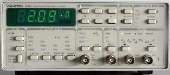
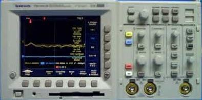
7 Wavete 81 Tetronix 301B Sync output Triggering input Signal output G8U oad 7
8 V(t) r out i(x,t) V(x,t) x dx C = capacitance per unit length = inductance per unit length CdxV dq; V q C t t i V = -C x t i; dv V x di ( dx) ; dt i dt 8
9 i x = -C V t V x i dt t x i tx C V t V x i xt (1) () Combining (1) and () i x C i t V x V t C 9
 V0 sin t i( x, t) i0 sin t v 1 C Speed of wave propagation Z - characteristic Impedance Equivalent to Ohm s law equation x v x v")
10 i x V x i C t i dt V x V C t Now substituting V(x,t) and i(x,t) in We can find V i 0 0 i x C V = -C t or V ( x, t) i( x, t) Z i( x, t) C ooing for solution V ( x, t) V0 sin t i( x, t) i0 sin t v 1 C Speed of wave propagation Z - characteristic Impedance Equivalent to Ohm s law equation x v x v 10

11 C = capacitance per unit length Z = C Cross-section of the coaxial cable = inductance per unitlength πε0εr C= (F/m) D ln d d D e r dielectric permittivity m r -magnetic permeability 1 ε = m mm 0 r D ln d -1 (F/m) -7 0 =4 10 (H/m) (H/m) Finally for coaxial cable: Z 138 D log ( Ohms ) e d r 11
12 1 = C Speed of wave propagation = 1 c c m m e e m e e 0 r 0 r r r r 1 Delay time G-8/U, G58U: 1 (s/m) 9 For polyethylene e r ~.5(up to 1GHz) e ( s / m) e ( ns / m) Inner Insulation Materials: Polyethylene Nominal Impedance: 5 ohm Delay time ~5ns/m r r 1

13 x reflected esistive load Z = Z forward V i V x solution for the traveling in opposite direction V C t For reflected wave V r =-Z i r At any point of the transmission line: V V V V Z i r i r or V r V ( x, t) V0 sin t i( x, t) i0 sin t Z V V V Z r i i i i r i Z V i i V x v x v V Z r 13
14 V V V V Z i r esistive load Z = i r or V r Z Z V i Open line = V r = V i Incident pulse eflected pulse End of the line 14
15 Attenuation (db per 100 feet) Theory: = V r = V i MHz G-58U Experiment G 58U incident reflected V i V r V i ATTN ( db) 0log Vr Important parameter for cable is attenuation per length 15
16 In our case: 4.18 Attn(00 ft) 0 log 1.46dB 3.54 Where it is coming from? i i C i G i+1 16
 0 log 0.335dB 3.78 Dielectric ø=7.")
17 G-58U 4.18 Attn(00 ft ) 0 log 1.46dB 3.54 G-8U > Core ø=0.81 mm Core ø=.17 mm Dielectric ø=.9 mm 9/16/ Attn(00 ft ) 0 log 0.335dB 3.78 Dielectric ø=7. mm Fall


18 eflected pulse does not follow the shape of the incident pulse G-58U Frequency dependence of the attenuation G-58U cable 18
19 FFT Spectrum correction Incident pulse spectrum reflected pulse spectrum IFFT 19
20 V V V V Z i r esistive load Z = i r or V r Z Z V i Shorted line =0 V r = - V i Incident pulse V(V) eflected pulse time (ns) 0
21 esistive load Z = Vi Vr V V Z i r or V r Z Z V i V (V) Matching the load impedance Z ; V r 0 Incident pulse V(V) Incident pulse time (ns) -0. V(V) time (ns) eflected pulse time (ns) 1 End of the line

 3 éon Charles Thévenin (1857 196) r 1 4")
22 Any combination of batteries and resistances with two terminals can be replaced by a single voltage source e and a single series resistor r Hermann udwig Ferdinand von Helmholtz ( ) 3 éon Charles Thévenin ( ) r E 1 E e + -

")
23 V V V i i i i r i V i r i Z V Z r i V i Z Z Vi From this equivalent equation we can find the maximum possible power delivered to V i P i Z P=P max if =Z (no reflection) 3
24 G 8U Pulse at the end of the line Vi Z incident reflected This experiment better to perform on G 8U cable because of lower attenuation =, amplitude of the pulse at the end of line is expected to be Vi, where Vi is the amplitude of the incident pulse 4
25 i V 0 V i Z Z Z di V i iz ; dt t i i0 1exp ; Z V i V V r = V - V i time 5
26 i V i Z Z di V i iz ; dt t i i0 1exp ; V 0 Z Z 50ns, =Z~. 5mH 6

27 i V i Z Z Z V 0 C Z C C 3. nf Z 7

28 8
29 1. The reports should be uploaded to the proper folder and only to the proper folder For example folder C ab eport_1 should used by students from 1 section only I would recommend the file name style as: 1_lab_student1 ab section ab number Your name. Origin template for this wee ab: \\engr-file-03\phyinst\ap Courses\PHYCS401\Common\Origin templates\transmission line\time trace.otp 9
30 limit s a serious to C circuit resistor Fitting parameters: (1) limit, () ω 0 = 1 C, (3) Q = 1 C Initial values can be estimated from circuit parameters. H 1 j limit j Q 0 limit 1 j Q j C 1 1 j Q1 0 Q 0 limit Q For fitting results and actual fitting function equation go to: \\engr-file-03\phyinst\ap Courses\PHYCS401\Common\Simple Examples\ ab 3 Frequency Domain Analysis_example.opj 30
31 Now to simplify the equation we can introduce the reduced frequency γ = ω ω 0 and transfer function components can be presented as: Q j 1 Q 1 H( ) Q ; 0 Q 1 H E Q Q 0 Q 1 ; H IM Q j 1 Q 1 0 Q 1 31
32 Two other components the modulus and the phase shift: H Q Q 0 Q 1 Q 1 1 ; arctan H H IM E arctan 1 Q 1 Q 3
33 X Y Data courtesy Tsung-in Hsieh, Physics 401, Fall
34 y = f(x1, x... xn) n f i i i i1 xi f ( x, x ) x 1.15 f(x i ) f±fx 1.10 x i ± x i x i 34
35 Derive resonance frequency f from measured inductance ± and capacitance C± C f (, C) C 10 1mH, C 10 μf 1 1 f f f (, C,, C) C C f f C 1 C C ; esults: f( 1,C 1 )= Hz f= hz f( 1,C 1 )=503±56Hz 35


36 10 1mH, C 10 1μF Where these numbers are coming from? Using commercial resistors, capacitors, inductances C=500pF±5% =35mH±10%. Measuring the parameters using standard equipment SENCOE Z meter model C53 Capacitance measuring accuracy ±5% Inductance measuring accuracy ±% Agilent E4980A Precision C Meter Basic accuracy ±0.05% 36
Pulses in transmission lines
 Pulses in transmission lines Physics 401, Fall 2018 Eugene V. Colla Definition Distributed parameters network Pulses in transmission line Wave equation and wave propagation Reflections. Resistive load
ELECTROMANETIC PULSE PROPAGATION IN A COAXIAL CABLE
 ELECTROMANETIC PULSE PROPAGATION IN A COAXIAL CABLE The mechanical waves on a stretched string are easily generated and observed but not easily studied in quantitative detail. The propagating waves in
Determining Characteristic Impedance and Velocity of Propagation by Measuring the Distributed Capacitance and Inductance of a Line
 Exercise 2-1 Determining Characteristic Impedance and Velocity EXERCISE OBJECTIVES Upon completion of this exercise, you will know how to measure the distributed capacitance and distributed inductance
Name. Section. Short Answer Questions. 1. (20 Pts) 2. (10 Pts) 3. (5 Pts) 4. (10 Pts) 5. (10 Pts) Regular Questions. 6. (25 Pts) 7.
 2. (10 Pts) 3. (5 Pts) 4. (10 Pts) 5. (10 Pts) Regular Questions. 6. (25 Pts) 7.") Name Section Short Answer Questions 1. (20 Pts) 2. (10 Pts) 3. (5 Pts). (10 Pts) 5. (10 Pts) Regular Questions 6. (25 Pts) 7. (20 Pts) Notes: 1. Please read over all questions before you begin your work.
Name Section Short Answer Questions 1. (20 Pts) 2. (10 Pts) 3. (5 Pts). (10 Pts) 5. (10 Pts) Regular Questions 6. (25 Pts) 7. (20 Pts) Notes: 1. Please read over all questions before you begin your work.
EELE 3332 Electromagnetic II Chapter 11. Transmission Lines. Islamic University of Gaza Electrical Engineering Department Dr.
 EEE 333 Electromagnetic II Chapter 11 Transmission ines Islamic University of Gaza Electrical Engineering Department Dr. Talal Skaik 1 1 11.1 Introduction Wave propagation in unbounded media is used in
ANTENNAS and MICROWAVES ENGINEERING (650427)
") Philadelphia University Faculty of Engineering Communication and Electronics Engineering ANTENNAS and MICROWAVES ENGINEERING (65427) Part 2 Dr. Omar R Daoud 1 General Considerations It is a two-port network
Philadelphia University Faculty of Engineering Communication and Electronics Engineering ANTENNAS and MICROWAVES ENGINEERING (65427) Part 2 Dr. Omar R Daoud 1 General Considerations It is a two-port network
Kimmo Silvonen, Transmission lines, ver
 Kimmo Silvonen, Transmission lines, ver. 13.10.2008 1 1 Basic Theory The increasing operating and clock frequencies require transmission line theory to be considered more and more often! 1.1 Some practical
ELECTRO MAGNETIC INDUCTION
 ELECTRO MAGNETIC INDUCTION 1) A Circular coil is placed near a current carrying conductor. The induced current is anti clock wise when the coil is, 1. Stationary 2. Moved away from the conductor 3. Moved
AC Circuits. The Capacitor
 The Capacitor Two conductors in close proximity (and electrically isolated from one another) form a capacitor. An electric field is produced by charge differences between the conductors. The capacitance
Basics of Network Theory (Part-I)
") Basics of Network Theory (Part-I) 1. One coulomb charge is equal to the charge on (a) 6.24 x 10 18 electrons (b) 6.24 x 10 24 electrons (c) 6.24 x 10 18 atoms (d) none of the above 2. The correct relation
Basics of Network Theory (Part-I) 1. One coulomb charge is equal to the charge on (a) 6.24 x 10 18 electrons (b) 6.24 x 10 24 electrons (c) 6.24 x 10 18 atoms (d) none of the above 2. The correct relation
INTRODUCTION TO TRANSMISSION LINES DR. FARID FARAHMAND FALL 2012
 INTRODUCTION TO TRANSMISSION LINES DR. FARID FARAHMAND FALL 2012 http://www.empowermentresources.com/stop_cointelpro/electromagnetic_warfare.htm RF Design In RF circuits RF energy has to be transported
Topic 5: Transmission Lines
 Topic 5: Transmission Lines Profs. Javier Ramos & Eduardo Morgado Academic year.13-.14 Concepts in this Chapter Mathematical Propagation Model for a guided transmission line Primary Parameters Secondary
PHYS 241 EXAM #2 November 9, 2006
 1. ( 5 points) A resistance R and a 3.9 H inductance are in series across a 60 Hz AC voltage. The voltage across the resistor is 23 V and the voltage across the inductor is 35 V. Assume that all voltages
Your RF Cable, the unknown Entity
 HAM RADIO 2018 Your RF Cable, the unknown Entity PROF. DR. THOMAS BAIER E-mail: baier@hs-ulm.de DG8SAQ Hochschule Ulm University of Applied Sciences Prittwitzstrasse 10 89075 Ulm Thanks to: Dan Maguire
PHY3128 / PHYM203 (Electronics / Instrumentation) Transmission Lines
 Transmission Lines") Transmission Lines Introduction A transmission line guides energy from one place to another. Optical fibres, waveguides, telephone lines and power cables are all electromagnetic transmission lines. are
Transmission Lines Introduction A transmission line guides energy from one place to another. Optical fibres, waveguides, telephone lines and power cables are all electromagnetic transmission lines. are
Chapter 6 Objectives
 hapter 6 Engr8 ircuit Analysis Dr urtis Nelson hapter 6 Objectives Understand relationships between voltage, current, power, and energy in inductors and capacitors; Know that current must be continuous
Wave Phenomena Physics 15c. Lecture 8 LC Transmission Line Wave Reflection
 Wave Phenomena Physics 15c Lecture 8 LC Transmission Line Wave Reflection Midterm Exam #1 Midterm #1 has been graded Class average = 80.4 Standard deviation = 14.6 Your exam will be returned in the section
and Ee = E ; 0 they are separated by a dielectric material having u = io-s S/m, µ, = µ, 0
 602 CHAPTER 11 TRANSMISSION LINES 11.10 Two identical pulses each of magnitude 12 V and width 2 µs are incident at t = 0 on a lossless transmission line of length 400 m terminated with a load. If the two
 Alternating Currents. The power is transmitted from a power house on high voltage ac because (a) Electric current travels faster at higher volts (b) It is more economical due to less power wastage (c)
Transmission Line Basics II - Class 6
 Transmission Line Basics II - Class 6 Prerequisite Reading assignment: CH2 Acknowledgements: Intel Bus Boot Camp: Michael Leddige Agenda 2 The Transmission Line Concept Transmission line equivalent circuits
Physics 405/505 Digital Electronics Techniques. University of Arizona Spring 2006 Prof. Erich W. Varnes
 Physics 405/505 Digital Electronics Techniques University of Arizona Spring 2006 Prof. Erich W. Varnes Administrative Matters Contacting me I will hold office hours on Tuesday from 1-3 pm Room 420K in
PHYS 1441 Section 001 Lecture #23 Monday, Dec. 4, 2017
 PHYS 1441 Section 1 Lecture #3 Monday, Dec. 4, 17 Chapter 3: Inductance Mutual and Self Inductance Energy Stored in Magnetic Field Alternating Current and AC Circuits AC Circuit W/ LRC Chapter 31: Maxwell
EE Branch GATE Paper 2010
 Q.1 Q.25 carry one mark each 1. The value of the quantity P, where, is equal to 0 1 e 1/e 2. Divergence of the three-dimensional radial vector field is 3 1/r 3. The period of the signal x(t) = 8 is 0.4
Driven RLC Circuits Challenge Problem Solutions
 Driven LC Circuits Challenge Problem Solutions Problem : Using the same circuit as in problem 6, only this time leaving the function generator on and driving below resonance, which in the following pairs
2. Waves with higher frequencies travel faster than waves with lower frequencies (True/False)
") PHY 2049C Final Exam. Summer 2015. Name: Remember, you know this stuff Answer each questions to the best of your ability. Show ALL of your work (even for multiple choice questions), you may receive partial
PHY 2049C Final Exam. Summer 2015. Name: Remember, you know this stuff Answer each questions to the best of your ability. Show ALL of your work (even for multiple choice questions), you may receive partial
Prof. Anyes Taffard. Physics 120/220. Voltage Divider Capacitor RC circuits
 Prof. Anyes Taffard Physics 120/220 Voltage Divider Capacitor RC circuits Voltage Divider The figure is called a voltage divider. It s one of the most useful and important circuit elements we will encounter.
ELECTROMAGNETIC OSCILLATIONS AND ALTERNATING CURRENT
 Chapter 31: ELECTROMAGNETIC OSCILLATIONS AND ALTERNATING CURRENT 1 A charged capacitor and an inductor are connected in series At time t = 0 the current is zero, but the capacitor is charged If T is the
ECE 3318 Applied Electricity and Magnetism. Spring Prof. David R. Jackson Dept. of ECE. Notes 25 Capacitance
 EE 3318 pplied Electricity and Magnetism Spring 218 Prof. David R. Jackson Dept. of EE Notes 25 apacitance 1 apacitance apacitor [F] + V - +Q ++++++++++++++++++ - - - - - - - - - - - - - - - - - Q ε r
ECE 241L Fundamentals of Electrical Engineering. Experiment 6 AC Circuits
 ECE 241L Fundamentals of Electrical Engineering Experiment 6 AC Circuits A. Objectives: Objectives: I. Calculate amplitude and phase angles of a-c voltages and impedances II. Calculate the reactance and
Direct Current (DC) Circuits
 Circuits") Direct Current (DC) Circuits NOTE: There are short answer analysis questions in the Participation section the informal lab report. emember to include these answers in your lab notebook as they will be
Direct Current (DC) Circuits NOTE: There are short answer analysis questions in the Participation section the informal lab report. emember to include these answers in your lab notebook as they will be
Phys 2025, First Test. September 20, minutes Name:
 Phys 05, First Test. September 0, 011 50 minutes Name: Show all work for maximum credit. Each problem is worth 10 points. Work 10 of the 11 problems. k = 9.0 x 10 9 N m / C ε 0 = 8.85 x 10⁻¹ C / N m e
ENGR 2405 Chapter 6. Capacitors And Inductors
 ENGR 2405 Chapter 6 Capacitors And Inductors Overview This chapter will introduce two new linear circuit elements: The capacitor The inductor Unlike resistors, these elements do not dissipate energy They
AP Physics C. Electric Circuits III.C
 AP Physics C Electric Circuits III.C III.C.1 Current, Resistance and Power The direction of conventional current Suppose the cross-sectional area of the conductor changes. If a conductor has no current,
Agenda for Today. Elements of Physics II. Capacitors Parallel-plate. Charging of capacitors
 Capacitors Parallel-plate Physics 132: Lecture e 7 Elements of Physics II Charging of capacitors Agenda for Today Combinations of capacitors Energy stored in a capacitor Dielectrics in capacitors Physics
18 - ELECTROMAGNETIC INDUCTION AND ALTERNATING CURRENTS ( Answers at the end of all questions ) Page 1
 Page 1") ( Answers at the end of all questions ) Page ) The self inductance of the motor of an electric fan is 0 H. In order to impart maximum power at 50 Hz, it should be connected to a capacitance of 8 µ F (
( Answers at the end of all questions ) Page ) The self inductance of the motor of an electric fan is 0 H. In order to impart maximum power at 50 Hz, it should be connected to a capacitance of 8 µ F (
Physics 2B Spring 2010: Final Version A 1 COMMENTS AND REMINDERS:
 Physics 2B Spring 2010: Final Version A 1 COMMENTS AND REMINDERS: Closed book. No work needs to be shown for multiple-choice questions. 1. A charge of +4.0 C is placed at the origin. A charge of 3.0 C
A) I B) II C) III D) IV E) V
 I B) II C) III D) IV E) V") 1. A square loop of wire moves with a constant speed v from a field-free region into a region of uniform B field, as shown. Which of the five graphs correctly shows the induced current i in the loop as
1. A square loop of wire moves with a constant speed v from a field-free region into a region of uniform B field, as shown. Which of the five graphs correctly shows the induced current i in the loop as
Sinusoidal Response of RLC Circuits
 Sinusoidal Response of RLC Circuits Series RL circuit Series RC circuit Series RLC circuit Parallel RL circuit Parallel RC circuit R-L Series Circuit R-L Series Circuit R-L Series Circuit Instantaneous
Electric Currents & Resistance
 Electric Currents & Resistance Electric Battery A battery produces electricity by transforming chemical energy into electrical energy. The simplest battery contains two plates or rods made of dissimilar
Chapter 21: RLC Circuits. PHY2054: Chapter 21 1
 Chapter 21: RC Circuits PHY2054: Chapter 21 1 Voltage and Current in RC Circuits AC emf source: driving frequency f ε = ε sinωt ω = 2π f m If circuit contains only R + emf source, current is simple ε ε
ECE 241L Fundamentals of Electrical Engineering. Experiment 5 Transient Response
 ECE 241L Fundamentals of Electrical Engineering Experiment 5 Transient Response NAME PARTNER A. Objectives: I. Learn how to use the function generator and oscilloscope II. Measure step response of RC and
TECHNO INDIA BATANAGAR
 TECHNO INDIA BATANAGAR ( DEPARTMENT OF ELECTRONICS & COMMUNICATION ENGINEERING) QUESTION BANK- 2018 1.Vector Calculus Assistant Professor 9432183958.mukherjee@tib.edu.in 1. When the operator operates on
UNIVERSITY OF BOLTON. SCHOOL OF ENGINEERING, SPORTS and SCIENCES BENG (HONS) ELECTRICAL & ELECTRONICS ENGINEERING EXAMINATION SEMESTER /2018
 ELECTRICAL & ELECTRONICS ENGINEERING EXAMINATION SEMESTER /2018") ENG018 SCHOOL OF ENGINEERING, SPORTS and SCIENCES BENG (HONS) ELECTRICAL & ELECTRONICS ENGINEERING MODULE NO: EEE6002 Date: 17 January 2018 Time: 2.00 4.00 INSTRUCTIONS TO CANDIDATES: There are six questions.
ENG018 SCHOOL OF ENGINEERING, SPORTS and SCIENCES BENG (HONS) ELECTRICAL & ELECTRONICS ENGINEERING MODULE NO: EEE6002 Date: 17 January 2018 Time: 2.00 4.00 INSTRUCTIONS TO CANDIDATES: There are six questions.
Introduction to AC Circuits (Capacitors and Inductors)
") Introduction to AC Circuits (Capacitors and Inductors) Amin Electronics and Electrical Communications Engineering Department (EECE) Cairo University elc.n102.eng@gmail.com http://scholar.cu.edu.eg/refky/
Introduction to AC Circuits (Capacitors and Inductors) Amin Electronics and Electrical Communications Engineering Department (EECE) Cairo University elc.n102.eng@gmail.com http://scholar.cu.edu.eg/refky/
Transmission lines. Shouri Chatterjee. October 22, 2014
 Transmission lines Shouri Chatterjee October 22, 2014 The transmission line is a very commonly used distributed circuit: a pair of wires. Unfortunately, a pair of wires used to apply a time-varying voltage,
Chapter 33. Alternating Current Circuits
 Chapter 33 Alternating Current Circuits 1 Capacitor Resistor + Q = C V = I R R I + + Inductance d I Vab = L dt AC power source The AC power source provides an alternative voltage, Notation - Lower case
Physics 240 Fall 2005: Exam #3 Solutions. Please print your name: Please list your discussion section number: Please list your discussion instructor:
 Physics 4 Fall 5: Exam #3 Solutions Please print your name: Please list your discussion section number: Please list your discussion instructor: Form #1 Instructions 1. Fill in your name above. This will
AC Circuits Homework Set
 Problem 1. In an oscillating LC circuit in which C=4.0 μf, the maximum potential difference across the capacitor during the oscillations is 1.50 V and the maximum current through the inductor is 50.0 ma.
ESE 570: Digital Integrated Circuits and VLSI Fundamentals
 ESE 570: Digital Integrated Circuits and VLSI Fundamentals Lec 24: April 19, 2018 Crosstalk and Wiring, Transmission Lines Lecture Outline! Crosstalk! Repeaters in Wiring! Transmission Lines " Where transmission
PHYSICS 2B FINAL EXAM ANSWERS WINTER QUARTER 2010 PROF. HIRSCH MARCH 18, 2010 Problems 1, 2 P 1 P 2
 Problems 1, 2 P 1 P 1 P 2 The figure shows a non-conducting spherical shell of inner radius and outer radius 2 (i.e. radial thickness ) with charge uniformly distributed throughout its volume. Prob 1:
ECE 107: Electromagnetism
 ECE 107: Electromagnetism Set 2: Transmission lines Instructor: Prof. Vitaliy Lomakin Department of Electrical and Computer Engineering University of California, San Diego, CA 92093 1 Outline Transmission
A) n 1 > n 2 > n 3 B) n 1 > n 3 > n 2 C) n 2 > n 1 > n 3 D) n 2 > n 3 > n 1 E) n 3 > n 1 > n 2
 n 1 > n 2 > n 3 B) n 1 > n 3 > n 2 C) n 2 > n 1 > n 3 D) n 2 > n 3 > n 1 E) n 3 > n 1 > n 2") 55) The diagram shows the path of a light ray in three different materials. The index of refraction for each material is shown in the upper right portion of the material. What is the correct order for
55) The diagram shows the path of a light ray in three different materials. The index of refraction for each material is shown in the upper right portion of the material. What is the correct order for
PHYSICS : CLASS XII ALL SUBJECTIVE ASSESSMENT TEST ASAT
 PHYSICS 202 203: CLASS XII ALL SUBJECTIVE ASSESSMENT TEST ASAT MM MARKS: 70] [TIME: 3 HOUR General Instructions: All the questions are compulsory Question no. to 8 consist of one marks questions, which
Electrodynamics Qualifier Examination
 Electrodynamics Qualifier Examination August 15, 2007 General Instructions: In all cases, be sure to state your system of units. Show all your work, write only on one side of the designated paper, and
Agenda for Today. Elements of Physics II. Capacitors Parallel-plate. Charging of capacitors
 Capacitors Parallel-plate Physics 132: Lecture e 7 Elements of Physics II Charging of capacitors Agenda for Today Combinations of capacitors Energy stored in a capacitor Dielectrics in capacitors Physics
Physics 420 Fall 2004 Quiz 1 Wednesday This quiz is worth 6 points. Be sure to show your work and label your final answers.
 Quiz 1 Wednesday This quiz is worth 6 points. Be sure to show your work and label your final answers. 1. A charge q 1 = +5.0 nc is located on the y-axis, 15 µm above the origin, while another charge q
! Crosstalk. ! Repeaters in Wiring. ! Transmission Lines. " Where transmission lines arise? " Lossless Transmission Line.
 ESE 570: Digital Integrated Circuits and VLSI Fundamentals Lec 24: April 19, 2018 Crosstalk and Wiring, Transmission Lines Lecture Outline! Crosstalk! Repeaters in Wiring! Transmission Lines " Where transmission
GATE 2010 Electrical Engineering
 GATE 2010 Electrical Engineering Q.1 Q.25 carry one mark each 1. The value of the quantity P, where P = xe dx, is equal to (A) 0 (B) 1 (C) e (D) 1/e 2. Divergence of the three-dimensional radial vector
ECE357H1S ELECTROMAGNETIC FIELDS TERM TEST March 2016, 18:00 19:00. Examiner: Prof. Sean V. Hum
 UNIVERSITY OF TORONTO FACULTY OF APPLIED SCIENCE AND ENGINEERING The Edward S. Rogers Sr. Department of Electrical and Computer Engineering ECE357H1S ELECTROMAGNETIC FIELDS TERM TEST 2 21 March 2016, 18:00
2 Signal Frequency and Impedances First Order Filter Circuits Resonant and Second Order Filter Circuits... 13
 Lecture Notes: 3454 Physics and Electronics Lecture ( nd Half), Year: 7 Physics Department, Faculty of Science, Chulalongkorn University //7 Contents Power in Ac Circuits Signal Frequency and Impedances
12 Chapter Driven RLC Circuits
 hapter Driven ircuits. A Sources... -. A ircuits with a Source and One ircuit Element... -3.. Purely esistive oad... -3.. Purely Inductive oad... -6..3 Purely apacitive oad... -8.3 The Series ircuit...
Version 001 CIRCUITS holland (1290) 1
 1") Version CIRCUITS holland (9) This print-out should have questions Multiple-choice questions may continue on the next column or page find all choices before answering AP M 99 MC points The power dissipated
Version CIRCUITS holland (9) This print-out should have questions Multiple-choice questions may continue on the next column or page find all choices before answering AP M 99 MC points The power dissipated
Final on December Physics 106 R. Schad. 3e 4e 5c 6d 7c 8d 9b 10e 11d 12e 13d 14d 15b 16d 17b 18b 19c 20a
 Final on December11. 2007 - Physics 106 R. Schad YOUR NAME STUDENT NUMBER 3e 4e 5c 6d 7c 8d 9b 10e 11d 12e 13d 14d 15b 16d 17b 18b 19c 20a 1. 2. 3. 4. This is to identify the exam version you have IMPORTANT
Physics 240 Fall 2005: Exam #3. Please print your name: Please list your discussion section number: Please list your discussion instructor:
 Physics 240 Fall 2005: Exam #3 Please print your name: Please list your discussion section number: Please list your discussion instructor: Form #1 Instructions 1. Fill in your name above 2. This will be
Lecture 35: FRI 17 APR Electrical Oscillations, LC Circuits, Alternating Current I
 Physics 3 Jonathan Dowling Lecture 35: FRI 7 APR Electrical Oscillations, LC Circuits, Alternating Current I Nikolai Tesla What are we going to learn? A road map Electric charge è Electric force on other
Electronics. Basics & Applications. group talk Daniel Biesinger
 Electronics Basics & Applications group talk 23.7.2010 by Daniel Biesinger 1 2 Contents Contents Basics Simple applications Equivalent circuit Impedance & Reactance More advanced applications - RC circuits
Capacitance and Dielectrics. Chapter 26 HW: P: 10,18,21,29,33,48, 51,53,54,68
 Capacitance and Dielectrics Chapter 26 HW: P: 10,18,21,29,33,48, 51,53,54,68 Capacitors Capacitors are devices that store electric charge and energy Examples of where capacitors are used include: radio
Chapter 24 Capacitance and Dielectrics
 Chapter 24 Capacitance and Dielectrics 1 Capacitors and Capacitance A capacitor is a device that stores electric potential energy and electric charge. The simplest construction of a capacitor is two parallel
Schedule. ECEN 301 Discussion #20 Exam 2 Review 1. Lab Due date. Title Chapters HW Due date. Date Day Class No. 10 Nov Mon 20 Exam Review.
 Schedule Date Day lass No. 0 Nov Mon 0 Exam Review Nov Tue Title hapters HW Due date Nov Wed Boolean Algebra 3. 3.3 ab Due date AB 7 Exam EXAM 3 Nov Thu 4 Nov Fri Recitation 5 Nov Sat 6 Nov Sun 7 Nov Mon
Module M2-1 Electrical Engineering
 Module M-1 Electrical Engineering TUTOIL 4 Topics Conductors (ต วนำไฟฟ า) Dielectrics or insulators (ฉนวนไฟฟ า) Capacitance CONDUCTOS ND DIELECTICS CPCITNCE SEPTEME 1, 016 fter this tutorial, you will
RADIO AMATEUR EXAM GENERAL CLASS
 RAE-Lessons by 4S7VJ 1 CHAPTER- 2 RADIO AMATEUR EXAM GENERAL CLASS By 4S7VJ 2.1 Sine-wave If a magnet rotates near a coil, an alternating e.m.f. (a.c.) generates in the coil. This e.m.f. gradually increase
CHAPTER 22 ELECTROMAGNETIC INDUCTION
 CHAPTER 22 ELECTROMAGNETIC INDUCTION PROBLEMS 47. REASONING AND Using Equation 22.7, we find emf 2 M I or M ( emf 2 ) t ( 0.2 V) ( 0.4 s) t I (.6 A) ( 3.4 A) 9.3 0 3 H 49. SSM REASONING AND From the results
Electromagnetic Oscillations and Alternating Current. 1. Electromagnetic oscillations and LC circuit 2. Alternating Current 3.
 Electromagnetic Oscillations and Alternating Current 1. Electromagnetic oscillations and LC circuit 2. Alternating Current 3. RLC circuit in AC 1 RL and RC circuits RL RC Charging Discharging I = emf R
Capacitance, Resistance, DC Circuits
 This test covers capacitance, electrical current, resistance, emf, electrical power, Ohm s Law, Kirchhoff s Rules, and RC Circuits, with some problems requiring a knowledge of basic calculus. Part I. Multiple
Graduate Diploma in Engineering Circuits and waves
 9210-112 Graduate Diploma in Engineering Circuits and waves You should have the following for this examination one answer book non-programmable calculator pen, pencil, ruler No additional data is attached
Laboratory I: Impedance
 Physics 33, Fall 2008 ab I - Exercises aboratory I: Impedance eading: ab handout Simpson hapter if necessary) & hapter 2 particularly 2.9-2.3) ab Exercises. Part I What is the input impedance of the oscilloscope
CHAPTER FOUR MUTUAL INDUCTANCE
 CHAPTER FOUR MUTUAL INDUCTANCE 4.1 Inductance 4.2 Capacitance 4.3 Serial-Parallel Combination 4.4 Mutual Inductance 4.1 Inductance Inductance (L in Henry is the circuit parameter used to describe an inductor.
Conventional Paper I-2010
 Conventional Paper I-010 1. (a) Sketch the covalent bonding of Si atoms in a intrinsic Si crystal Illustrate with sketches the formation of bonding in presence of donor and acceptor atoms. Sketch the energy
Lecture 11 - AC Power
 - AC Power 11/17/2015 Reading: Chapter 11 1 Outline Instantaneous power Complex power Average (real) power Reactive power Apparent power Maximum power transfer Power factor correction 2 Power in AC Circuits
ECE2262 Electric Circuits. Chapter 6: Capacitance and Inductance
 ECE2262 Electric Circuits Chapter 6: Capacitance and Inductance Capacitors Inductors Capacitor and Inductor Combinations Op-Amp Integrator and Op-Amp Differentiator 1 CAPACITANCE AND INDUCTANCE Introduces
DEPARTMENT OF COMPUTER ENGINEERING UNIVERSITY OF LAHORE
 DEPARTMENT OF COMPUTER ENGINEERING UNIVERSITY OF LAHORE NAME. Section 1 2 3 UNIVERSITY OF LAHORE Department of Computer engineering Linear Circuit Analysis Laboratory Manual 2 Compiled by Engr. Ahmad Bilal
Figure Circuit for Question 1. Figure Circuit for Question 2
 Exercises 10.7 Exercises Multiple Choice 1. For the circuit of Figure 10.44 the time constant is A. 0.5 ms 71.43 µs 2, 000 s D. 0.2 ms 4 Ω 2 Ω 12 Ω 1 mh 12u 0 () t V Figure 10.44. Circuit for Question
Basics of Network Theory (Part-I)
") Basics of Network Theory (PartI). A square waveform as shown in figure is applied across mh ideal inductor. The current through the inductor is a. wave of peak amplitude. V 0 0.5 t (m sec) [Gate 987: Marks]
Basics of Network Theory (PartI). A square waveform as shown in figure is applied across mh ideal inductor. The current through the inductor is a. wave of peak amplitude. V 0 0.5 t (m sec) [Gate 987: Marks]
Introduction to RF Design. RF Electronics Spring, 2016 Robert R. Krchnavek Rowan University
 Introduction to RF Design RF Electronics Spring, 2016 Robert R. Krchnavek Rowan University Objectives Understand why RF design is different from lowfrequency design. Develop RF models of passive components.
MCE603: Interfacing and Control of Mechatronic Systems. Chapter 1: Impedance Analysis for Electromechanical Interfacing
 MCE63: Interfacing and Control of Mechatronic Systems Chapter 1: Impedance Analysis for Electromechanical Interfacing Part B: Input and Output Impedance Cleveland State University Mechanical Engineering
IMPORTANT Read these directions carefully:
 Physics 208: Electricity and Magnetism Common Exam 2, October 17 th 2016 Print your name neatly: First name: Last name: Sign your name: Please fill in your Student ID number (UIN): _ - - Your classroom
Impedance/Reactance Problems
 Impedance/Reactance Problems. Consider the circuit below. An AC sinusoidal voltage of amplitude V and frequency ω is applied to the three capacitors, each of the same capacitance C. What is the total reactance
TRANSMISSION LINES. All aluminum alloy conductor (AAAC) Aluminum conductor alloy reinforced (ACAR)
 Aluminum conductor alloy reinforced (ACAR)") TRANSMISSION LINES. Transmission Structures An overhead transmission line consists of conductor, insulators, support structures and in most cases shield wires. Overhead power transmission lines are classified
TRANSMISSION LINES. Transmission Structures An overhead transmission line consists of conductor, insulators, support structures and in most cases shield wires. Overhead power transmission lines are classified
Experiment FT1: Measurement of Dielectric Constant
 Experiment FT1: Measurement of Dielectric Constant Name: ID: 1. Objective: (i) To measure the dielectric constant of paper and plastic film. (ii) To examine the energy storage capacity of a practical capacitor.
University of California, Berkeley Physics H7B Spring 1999 (Strovink) SOLUTION TO PROBLEM SET 11 Solutions by P. Pebler
 SOLUTION TO PROBLEM SET 11 Solutions by P. Pebler") University of California Berkeley Physics H7B Spring 999 (Strovink) SOLUTION TO PROBLEM SET Solutions by P. Pebler Purcell 7.2 A solenoid of radius a and length b is located inside a longer solenoid of
University of California Berkeley Physics H7B Spring 999 (Strovink) SOLUTION TO PROBLEM SET Solutions by P. Pebler Purcell 7.2 A solenoid of radius a and length b is located inside a longer solenoid of
PHYSICS ASSIGNMENT ES/CE/MAG. Class XII
 PHYSICS ASSIGNMENT ES/CE/MAG Class XII MM : 70 1. What is dielectric strength of a medium? Give its value for vacuum. 1 2. What is the physical importance of the line integral of an electrostatic field?
1.3 Sinusoidal Steady State
 1.3 Sinusoidal Steady State Electromagnetics applications can be divided into two broad classes: Time-domain: Excitation is not sinusoidal (pulsed, broadband, etc.) Ultrawideband communications Pulsed
Physics 4B Chapter 31: Electromagnetic Oscillations and Alternating Current
 Physics 4B Chapter 31: Electromagnetic Oscillations and Alternating Current People of mediocre ability sometimes achieve outstanding success because they don't know when to quit. Most men succeed because
AP Physics Electricity and Magnetism #3 Capacitors, Resistors, Ohm s Law, Electric Power
 Name Period AP Physics Electricity and Magnetism #3 Capacitors, Resistors, Ohm s Law, Electric Power Dr. Campbell 1. The two plates of a capacitor hold +2500 µc and -2500 µc of charge, respectively, when
University of TN Chattanooga Physics 1040L 8/18/2012 PHYSICS 1040L LAB LAB 4: R.C. TIME CONSTANT LAB
 PHYSICS 1040L LAB LAB 4: R.C. TIME CONSTANT LAB OBJECT: To study the discharging of a capacitor and determine the time constant for a simple circuit. APPARATUS: Capacitor (about 24 μf), two resistors (about
DOING PHYSICS WITH MATLAB
 DOING PHYSIS WITH MATAB THE FINITE DIFFERENE METHOD FOR THE NUMERIA ANAYSIS OF IRUITS ONTAINING RESISTORS, APAITORS AND INDUTORS MATAB DOWNOAD DIRETORY N01.m Voltage and current for a resistor, capacitor
PHY102 Electricity Course Summary
 TOPIC 1 ELECTOSTTICS PHY1 Electricity Course Summary Coulomb s Law The magnitude of the force between two point charges is directly proportional to the product of the charges and inversely proportional
Chapter 31 Electromagnetic Oscillations and Alternating Current LC Oscillations, Qualitatively
 Chapter 3 Electromagnetic Oscillations and Alternating Current LC Oscillations, Qualitatively In the LC circuit the charge, current, and potential difference vary sinusoidally (with period T and angular
General Physics II (PHYS 104) Exam 2: March 21, 2002
 Exam 2: March 21, 2002") General Physics II (PHYS 104) Exam 2: March 21, 2002 Name: Multiple Choice (3 points each): Answer the following multiple choice questions. Clearly circle the response (or responses) that provides the
General Physics II (PHYS 104) Exam 2: March 21, 2002 Name: Multiple Choice (3 points each): Answer the following multiple choice questions. Clearly circle the response (or responses) that provides the
EE-0001 PEEE Refresher Course. Week 1: Engineering Fundamentals
 EE-000 PEEE efresher Course Week : Engineering Fundamentals Engineering Fundamentals Bentley Chapters & Camara Chapters,, & 3 Electrical Quantities Energy (work), power, charge, current Electrostatic pressure,