Digital Logic Design ENEE x. Lecture 14
|
|
|
- Paul Austin
- 5 years ago
- Views:
Transcription
1 Digital Logic Design ENEE x Lecture 14
2 Announcements Homework 6 due today
3 Agenda Last time: Binary Adders and Subtracters (5.1, 5.1.1) Carry Lookahead Adders (5.1.2, 5.1.3) This time: Decimal Adders (5.2) Comparators (5.3) Decoders (5.4) Encoders (5.5) Multiplexers (5.6) After introducing all the MSI components, we will go back and talk about how to use Decoders and Multiplexers for Logic Design.
4 Decimal Adders 8421 weighted coding scheme or BCD Code Decimal Digit BCD Forbidden codes: 1010, 1011, 1100, 1101, 1110, 1111
5 Decimal Adder Inputs: A 3 A 2 A 1 A 0, B 3 B 2 B 1 B 0, C in from previous decade. Output: C out (carry to next decade), Z 3 Z 2 Z 1 Z 0. Idea: Perform regular binary addition and then apply a corrective procedure.
6 Comparing Binary and BCD Sums Decimal Sum K P 3 P 2 P 1 P 0 C out Z 3 Z 2 Z 1 Z Same C out is set to 0
7 Decimal Adder No correction needed when the decimal sum is between 0-9. Must apply a correction when the sum is between Case 1: 16-19: K is set to 1. Add binary quantity 0110 to P 3 P 2 P 1 P : KP 3 P 2 P 1 P 0 are set to 01010, 01011,.., Need to add 6. Use a K-map to obtain a Boolean expression to detect these six binary combinations.
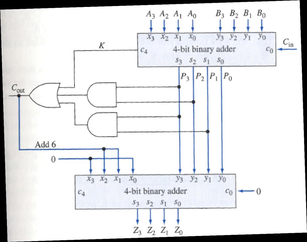
8 A single-decade BCD Adder
9 Comparators Compare the magnitude of two binary numbers for the purpose of establishing whether one is greater than, equal to, or less than the other. A comparator makes use of a cascade connection of identical subnetworks similar to the case of the parallel adder.
10 Comparators Consider two n-bit binary numbers: A = A n 1 A i A i 1 A 1 A 0 B = B n 1 B i B i 1 B 1 B 0 Assume A i, B i are entering the subnetwork and that the binary numbers are analyzed from right to left. Subnetwork is called a 1-bit comparator.
11 Comparators 3 conditions describing the relative magnitudes of A i 1 A 1 A 0, B i 1 B 1 B 0 G i = 1 denotes A i 1 A 1 A 0 > B i 1 B 1 B 0 E i = 1 denotes A i 1 A 1 A 0 = B i 1 B 1 B 0 L i = 1 denotes A i 1 A 1 A 0 < B i 1 B 1 B 0 1-bit comparator is a 5-input 3-output network
12 Comparators Rules: If A i = 0, B i = 1 then L i = 1 If A i = 1, B i = 0 then G i = 1 If A i = B i and L i 1 = 1 then L i = 1 If A i = B i and G i 1 = 1 then G i = 1 If A i = B i and E i 1 = 1 then E i = 1 Can use this to construct a truth table.
13 Comparators Minimal Sum Boolean Expressions: G i+1 = A i B i + A i G i + B i G i E i+1 = A i B i E i + A i B i E i L i+1 = A i B i + B i L i + A i L i
14 Comparators

15 Comparators
16 Decoder Digital information represented in some binary form must be converted into some alternate binary form. n to 2 n -line decoder. Only one of the 2 n output lines responds, with a logic-1, to a given input combination of values on its n-input lines.

17 Realization Symbol Logic Diagram Truth Table
18 Decoder Input combinations can be regarded as binary numbers with the consequences that the j-th output line is at logic-1 for j = 0, 1,.., 7 only when input combination j is applied.
19 Decoders with an Enable Input Logic Diagram Symbol Truth Table
20 Decoders with enable inputs When disabled, all outputs of the decoder can either be at logic-0 or logic-1. Enable input provides the decoder with additional flexibility. Idea: data is applied to the enable input. Process is known as demultiplexing. x 0 x 1 E Data If x 0 = 0, x 1 = 0 then data appears on line z 0. Enable inputs are useful when constructing larger decoders from smaller decoders.
21 Constructing Larger Decoders
22 Encoders Encoders provide for the conversion of binary information from one form to another. Encoders are essentially the inverse of decoders. 2 n -to-n-line encoder in which an assertive logic value on one of its 2 n -input lines causes the corresponding binary code to appear at the output lines. x 0 x 1 x 2 x 3 x 4 x 5 x 6 x 7 z 0 z 1 z
23 Encoders Equations for 8-to-3-line encoder: z 0 = x 1 + x 3 + x 5 + x 7 z 1 = x 2 + x 3 + x 6 + x 7 z 2 = x 4 + x 5 + x 6 + x 7 In general, the Boolean expression for the output z i is the sum of each input x j in which the binary representation of j has a 1 in the 2 i -bit position.
24 Priority Encoder The assumption that at most a single input to the encoder is asserted at any time is significant in its operation. Example: Both x 3 (11) and x 5 (101) are asserted. What is the output? 111 x 7 Priority Encoder: A priority scheme is assigned to the input lines so that whenever more than one input line is asserted at any time, the output is determined by the input line having the highest priority.

25 Priority Encoder The output is determined by the asserted input having the highest index. x i has higher priority than x j if i > j. Valid indicates that at least one input line is asserted. This distinguishes the situation that no input line is asserted from when the x 0 input line is asserted, since in both cases z 2 z 1 z 0 = 000.
26 Multiplexer Also called data selectors. Basic function: select one of its 2 n data input lines and place the corresponding information onto a single output line. n input bits needed to specify which input line is to be selected. Place binary code for a desired data input line onto its n select input lines.
27 Realization of 4-to-1 line multiplexer Symbol Logic Diagram Truth Table

28 Realization of 4-to-1 line multiplexer Alternate description: Algebraic description of multiplexer: f = I 0 S 1 S 0 + I 1 S 1 S 0 + I 2 S 1 S 0 + I 3 S 1 S 2 E
29 Building a Large Multiplexer
30 Multiplexers One of the primary applications of multiplexers is to provide for the transmission of information from several sources over a single path. This process is known as multiplexing. Demultiplexer = decoder with an enable input.
31 Multiplexer/Demultiplexer for information transmission
32
Chapter 4. Combinational: Circuits with logic gates whose outputs depend on the present combination of the inputs. elements. Dr.
 Chapter 4 Dr. Panos Nasiopoulos Combinational: Circuits with logic gates whose outputs depend on the present combination of the inputs. Sequential: In addition, they include storage elements Combinational
Systems I: Computer Organization and Architecture
 Systems I: Computer Organization and Architecture Lecture 6 - Combinational Logic Introduction A combinational circuit consists of input variables, logic gates, and output variables. The logic gates accept
Function of Combinational Logic ENT263
 Function of Combinational Logic ENT263 Chapter Objectives Distinguish between half-adder and full-adder Use BCD-to-7-segment decoders in display systems Apply multiplexer in data selection Use decoders
Unit 3 Session - 9 Data-Processing Circuits
 Objectives Unit 3 Session - 9 Data-Processing Design of multiplexer circuits Discuss multiplexer applications Realization of higher order multiplexers using lower orders (multiplexer trees) Introduction
Combinational Logic. By : Ali Mustafa
 Combinational Logic By : Ali Mustafa Contents Adder Subtractor Multiplier Comparator Decoder Encoder Multiplexer How to Analyze any combinational circuit like this? Analysis Procedure To obtain the output
ECE 545 Digital System Design with VHDL Lecture 1. Digital Logic Refresher Part A Combinational Logic Building Blocks
 ECE 545 Digital System Design with VHDL Lecture Digital Logic Refresher Part A Combinational Logic Building Blocks Lecture Roadmap Combinational Logic Basic Logic Review Basic Gates De Morgan s Law Combinational
Combinational Logic. Mantıksal Tasarım BBM231. section instructor: Ufuk Çelikcan
 Combinational Logic Mantıksal Tasarım BBM23 section instructor: Ufuk Çelikcan Classification. Combinational no memory outputs depends on only the present inputs expressed by Boolean functions 2. Sequential
Number System. Decimal to binary Binary to Decimal Binary to octal Binary to hexadecimal Hexadecimal to binary Octal to binary
 Number System Decimal to binary Binary to Decimal Binary to octal Binary to hexadecimal Hexadecimal to binary Octal to binary BOOLEAN ALGEBRA BOOLEAN LOGIC OPERATIONS Logical AND Logical OR Logical COMPLEMENTATION
Logic. Combinational. inputs. outputs. the result. system can
 Digital Electronics Combinational Logic Functions Digital logic circuits can be classified as either combinational or sequential circuits. A combinational circuit is one where the output at any time depends
MODULAR CIRCUITS CHAPTER 7
 CHAPTER 7 MODULAR CIRCUITS A modular circuit is a digital circuit that performs a specific function or has certain usage. The modular circuits to be introduced in this chapter are decoders, encoders, multiplexers,
Chapter 3 Combinational Logic Design
 Logic and Computer Design Fundamentals Chapter 3 Combinational Logic Design Part 2 Combinational Logic Charles Kime & Thomas Kaminski 28 Pearson Education, Inc. (Hyperlinks are active in View Show mode)
COMBINATIONAL LOGIC CIRCUITS. Dr. Mudathir A. Fagiri
 COMBINATIONAL LOGIC CIRCUITS Dr. Mudathir A. Fagiri Standard Combinational Modules Decoder: Decode address Encoder: Encode address Multiplexer (Mux): Select data by address Demultiplexier (DeMux): Direct
ECE 545 Digital System Design with VHDL Lecture 1A. Digital Logic Refresher Part A Combinational Logic Building Blocks
 ECE 545 Digital System Design with VHDL Lecture A Digital Logic Refresher Part A Combinational Logic Building Blocks Lecture Roadmap Combinational Logic Basic Logic Review Basic Gates De Morgan s Laws
Chapter 4: Combinational Logic Solutions to Problems: [1, 5, 9, 12, 19, 23, 30, 33]
![Chapter 4: Combinational Logic Solutions to Problems: [1, 5, 9, 12, 19, 23, 30, 33]](/thumbs/81/84077758.jpg "Chapter 4: Combinational Logic Solutions to Problems: [1, 5, 9, 12, 19, 23, 30, 33]") Chapter 4: Combinational Logic Solutions to Problems: [, 5, 9, 2, 9, 23, 3, 33] Problem: 4- Consider the combinational circuit shown in Fig. P4-. (a) Derive the Boolean expressions for T through T 4. Evaluate
Chapter 4: Combinational Logic Solutions to Problems: [, 5, 9, 2, 9, 23, 3, 33] Problem: 4- Consider the combinational circuit shown in Fig. P4-. (a) Derive the Boolean expressions for T through T 4. Evaluate
COMBINATIONAL LOGIC FUNCTIONS
 COMBINATIONAL LOGIC FUNCTIONS Digital logic circuits can be classified as either combinational or sequential circuits. A combinational circuit is one where the output at any time depends only on the present
ECE 341. Lecture # 3
 ECE 341 Lecture # 3 Instructor: Zeshan Chishti zeshan@ece.pdx.edu October 7, 2013 Portland State University Lecture Topics Counters Finite State Machines Decoders Multiplexers Reference: Appendix A of
CSE 140 Lecture 11 Standard Combinational Modules. CK Cheng and Diba Mirza CSE Dept. UC San Diego
 CSE 4 Lecture Standard Combinational Modules CK Cheng and Diba Mirza CSE Dept. UC San Diego Part III - Standard Combinational Modules (Harris: 2.8, 5) Signal Transport Decoder: Decode address Encoder:
ว ตถ ประสงค ของบทเร ยน
 Logic Design with MSI Circuits ว ตถ ประสงค ของบทเร ยน ร จ กวงจรประเภท MSI เข าใจการทำงานของวงจร MSI ท ม ใช อย ท วไป สามารถประย กต ใช วงจร MSI ในการออกแบบวงจรลอจ กแบบต างๆ ได A. Yaicharoen 1 Type of Circuits
COSC 243. Introduction to Logic And Combinatorial Logic. Lecture 4 - Introduction to Logic and Combinatorial Logic. COSC 243 (Computer Architecture)
") COSC 243 Introduction to Logic And Combinatorial Logic 1 Overview This Lecture Introduction to Digital Logic Gates Boolean algebra Combinatorial Logic Source: Chapter 11 (10 th edition) Source: J.R. Gregg,
COSC 243 Introduction to Logic And Combinatorial Logic 1 Overview This Lecture Introduction to Digital Logic Gates Boolean algebra Combinatorial Logic Source: Chapter 11 (10 th edition) Source: J.R. Gregg,
CMSC 313 Lecture 18 Midterm Exam returned Assign Homework 3 Circuits for Addition Digital Logic Components Programmable Logic Arrays
 CMSC 33 Lecture 8 Midterm Exam returned ssign Homework 3 Circuits for ddition Digital Logic Components Programmable Logic rrays UMC, CMSC33, Richard Chang Half dder Inputs: and Outputs:
CprE 281: Digital Logic
 CprE 28: Digital Logic Instructor: Alexander Stoytchev http://www.ece.iastate.edu/~alexs/classes/ Decoders and Encoders CprE 28: Digital Logic Iowa State University, Ames, IA Copyright Alexander Stoytchev
Combinational Logic. Lan-Da Van ( 范倫達 ), Ph. D. Department of Computer Science National Chiao Tung University Taiwan, R.O.C.
, Ph. D. Department of Computer Science National Chiao Tung University Taiwan, R.O.C.") Combinational Logic ( 范倫達 ), Ph. D. Department of Computer Science National Chiao Tung University Taiwan, R.O.C. Fall, 2010 ldvan@cs.nctu.edu.tw http://www.cs.nctu.edu.tw/~ldvan/ Combinational Circuits
Combinational Logic ( 范倫達 ), Ph. D. Department of Computer Science National Chiao Tung University Taiwan, R.O.C. Fall, 2010 ldvan@cs.nctu.edu.tw http://www.cs.nctu.edu.tw/~ldvan/ Combinational Circuits
ENGIN 112 Intro to Electrical and Computer Engineering
 ENGIN 112 Intro to Electrical and Computer Engineering Lecture 17 Encoders and Decoders Overview Binary decoders Converts an n-bit code to a single active output Can be developed using AND/OR gates Can
ECE 2300 Digital Logic & Computer Organization
 ECE 23 Digital Logic & Computer Organization Spring 28 Combinational Building Blocks Lecture 5: Announcements Lab 2 prelab due tomorrow HW due Friday HW 2 to be posted on Thursday Lecture 4 to be replayed
CprE 281: Digital Logic
 CprE 28: Digital Logic Instructor: Alexander Stoytchev http://www.ece.iastate.edu/~alexs/classes/ Code Converters CprE 28: Digital Logic Iowa State University, Ames, IA Copyright Alexander Stoytchev HW
Digital System Design Combinational Logic. Assoc. Prof. Pradondet Nilagupta
 Digital System Design Combinational Logic Assoc. Prof. Pradondet Nilagupta pom@ku.ac.th Acknowledgement This lecture note is modified from Engin112: Digital Design by Prof. Maciej Ciesielski, Prof. Tilman
Sample Test Paper - I
 Scheme G Sample Test Paper - I Course Name : Computer Engineering Group Marks : 25 Hours: 1 Hrs. Q.1) Attempt any THREE: 09 Marks a) Define i) Propagation delay ii) Fan-in iii) Fan-out b) Convert the following:
ELCT201: DIGITAL LOGIC DESIGN
 ELCT201: DIGITAL LOGIC DESIGN Dr. Eng. Haitham Omran, haitham.omran@guc.edu.eg Dr. Eng. Wassim Alexan, wassim.joseph@guc.edu.eg Lecture 5 Following the slides of Dr. Ahmed H. Madian ذو الحجة 1438 ه Winter
Combinational Logic. Lan-Da Van ( 范倫達 ), Ph. D. Department of Computer Science National Chiao Tung University Taiwan, R.O.C.
, Ph. D. Department of Computer Science National Chiao Tung University Taiwan, R.O.C.") Combinational Logic ( 范倫達 ), Ph. D. Department of Computer Science National Chiao Tung University Taiwan, R.O.C. Fall, 2017 ldvan@cs.nctu.edu.tw http://www.cs.nctu.edu.tw/~ldvan/ Combinational Circuits
Combinational Logic ( 范倫達 ), Ph. D. Department of Computer Science National Chiao Tung University Taiwan, R.O.C. Fall, 2017 ldvan@cs.nctu.edu.tw http://www.cs.nctu.edu.tw/~ldvan/ Combinational Circuits
CMSC 313 Lecture 17. Focus Groups. Announcement: in-class lab Thu 10/30 Homework 3 Questions Circuits for Addition Midterm Exam returned
 Focus Groups CMSC 33 Lecture 7 Need good sample of all types of CS students Mon /7 & Thu /2, 2:3p-2:p & 6:p-7:3p Announcement: in-class lab Thu /3 Homework 3 Questions Circuits for Addition Midterm Exam
CSEE 3827: Fundamentals of Computer Systems. Combinational Circuits
 CSEE 3827: Fundamentals of Computer Systems Combinational Circuits Outline (M&K 3., 3.3, 3.6-3.9, 4.-4.2, 4.5, 9.4) Combinational Circuit Design Standard combinational circuits enabler decoder encoder
CMSC 313 Lecture 18 Midterm Exam returned Assign Homework 3 Circuits for Addition Digital Logic Components Programmable Logic Arrays
 MS 33 Lecture 8 Midterm Exam returned Assign Homework 3 ircuits for Addition Digital Logic omponents Programmable Logic Arrays UMB, MS33, Richard hang MS 33, omputer Organization & Assembly
MODEL ANSWER SUMMER 17 EXAMINATION Subject Title: Principles of Digital Techniques
 MODEL ANSWER SUMMER 17 EXAMINATION Subject Title: Principles of Digital Techniques Subject Code: Important Instructions to examiners: 1) The answers should be examined by key words and not as word-to-word
IT T35 Digital system desigm y - ii /s - iii
 UNIT - II Combinational Logic Adders subtractors code converters binary parallel adder decimal adder magnitude comparator encoders decoders multiplexers demultiplexers-binarymultiplier Parity generator
CHAPTER VI COMBINATIONAL LOGIC BUILDING BLOCKS
 CHAPTR VI- CHAPTR VI CHAPTR VI BUILDING BLOCKS R.M. Dansereau; v.. CHAPTR VI- COMBINAT. LOGIC INTRODUCTION -INTRODUCTION Combinational logic Output at any time is determined completely by the current input.
Philadelphia University Student Name: Student Number:
 Philadelphia University Student Name: Student Number: Faculty of Engineering Serial Number: Final Exam, Second Semester: 2015/2016 Dept. of Computer Engineering Course Title: Logic Circuits Date: 08/06/2016
Chapter 3 Ctd: Combinational Functions and Circuits
 Chapter 3 Ctd: Combinational Functions and Circuits 1 Value Fixing, Transferring, and Inverting Four different functions are possible as a function of single Boolean variable Transferring Inverting Value
Chapter 4: Designing Combinational Systems Uchechukwu Ofoegbu
 Chapter 4: Designing Combinational Systems Uchechukwu Ofoegbu Temple University Gate Delay ((1.1).1) ((1.0).0) ((0.1).1) ((0.1).0) ((1.1) = 1 0 s = sum c out carry-out a, b = added bits C = carry in a
Z = F(X) Combinational circuit. A combinational circuit can be specified either by a truth table. Truth Table
 Combinational circuit. A combinational circuit can be specified either by a truth table. Truth Table") Lesson Objectives In this lesson, you will learn about What are combinational circuits Design procedure of combinational circuits Examples of combinational circuit design Combinational Circuits Logic circuit
Lesson Objectives In this lesson, you will learn about What are combinational circuits Design procedure of combinational circuits Examples of combinational circuit design Combinational Circuits Logic circuit
MAHARASHTRA STATE BOARD OF TECHNICAL EDUCATION (Autonomous) (ISO/IEC Certified) State any two Boolean laws. (Any 2 laws 1 mark each)
 (ISO/IEC Certified) State any two Boolean laws. (Any 2 laws 1 mark each)") Subject Code: 17333 Model Answer Page 1/ 27 Important Instructions to examiners: 1) The answers should be examined by key words and not as word-to-word as given in the model answer scheme. 2) The model
Subject Code: 17333 Model Answer Page 1/ 27 Important Instructions to examiners: 1) The answers should be examined by key words and not as word-to-word as given in the model answer scheme. 2) The model
Class Website:
 ECE 20B, Winter 2003 Introduction to Electrical Engineering, II LECTURE NOTES #5 Instructor: Andrew B. Kahng (lecture) Email: abk@ece.ucsd.edu Telephone: 858-822-4884 office, 858-353-0550 cell Office:
3. Combinational Circuit Design
 CSEE 3827: Fundamentals of Computer Systems, Spring 2 3. Combinational Circuit Design Prof. Martha Kim (martha@cs.columbia.edu) Web: http://www.cs.columbia.edu/~martha/courses/3827/sp/ Outline (H&H 2.8,
Combina-onal Logic Chapter 4. Topics. Combina-on Circuit 10/13/10. EECE 256 Dr. Sidney Fels Steven Oldridge
 Combina-onal Logic Chapter 4 EECE 256 Dr. Sidney Fels Steven Oldridge Topics Combina-onal circuits Combina-onal analysis Design procedure simple combined to make complex adders, subtractors, converters
Part 1: Digital Logic and Gates. Analog vs. Digital waveforms. The digital advantage. In real life...
 Part 1: Digital Logic and Gates Analog vs Digital waveforms An analog signal assumes a continuous range of values: v(t) ANALOG A digital signal assumes discrete (isolated, separate) values Usually there
DESIGN AND IMPLEMENTATION OF ENCODERS AND DECODERS. To design and implement encoders and decoders using logic gates.
 DESIGN AND IMPLEMENTATION OF ENCODERS AND DECODERS AIM To design and implement encoders and decoders using logic gates. COMPONENTS REQUIRED S.No Components Specification Quantity 1. Digital IC Trainer
Lecture 2 Review on Digital Logic (Part 1)
") Lecture 2 Review on Digital Logic (Part 1) Xuan Silvia Zhang Washington University in St. Louis http://classes.engineering.wustl.edu/ese461/ Grading Engagement 5% Review Quiz 10% Homework 10% Labs 40%
Lecture 2 Review on Digital Logic (Part 1) Xuan Silvia Zhang Washington University in St. Louis http://classes.engineering.wustl.edu/ese461/ Grading Engagement 5% Review Quiz 10% Homework 10% Labs 40%
CMSC 313 Lecture 19 Homework 4 Questions Combinational Logic Components Programmable Logic Arrays Introduction to Circuit Simplification
 CMSC 33 Lecture 9 Homework 4 Questions Combinational Logic Components Programmable Logic rrays Introduction to Circuit Simplification UMC, CMSC33, Richard Chang CMSC 33, Computer Organization
A B OUT_0 OUT_1 OUT_2 OUT_
 A B OUT_0 OUT_1 OUT_2 OUT_3 0 0 1 0 0 0 0 1 0 1 0 0 1 0 0 0 1 0 1 1 0 0 0 1 A Decoder is something that does the opposite of encoding; it converts the data back into its original form. This decoder converts
Combinational Logic Design Combinational Functions and Circuits
 Combinational Logic Design Combinational Functions and Circuits Overview Combinational Circuits Design Procedure Generic Example Example with don t cares: BCD-to-SevenSegment converter Binary Decoders
Digital Logic Design ENEE x. Lecture 12
 Digital Logic Design ENEE 244-010x Lecture 12 Announcements HW5 due today HW6 up on course webpage, due at the beginning of class on Wednesday, 10/28. Agenda Last time: Quine-McClusky (4.8) Petrick s Method
Hardware Design I Chap. 4 Representative combinational logic
 Hardware Design I Chap. 4 Representative combinational logic E-mail: shimada@is.naist.jp Already optimized circuits There are many optimized circuits which are well used You can reduce your design workload
SIR C.R.REDDY COLLEGE OF ENGINEERING ELURU DIGITAL INTEGRATED CIRCUITS (DIC) LABORATORY MANUAL III / IV B.E. (ECE) : I - SEMESTER
 LABORATORY MANUAL III / IV B.E. (ECE) : I - SEMESTER") SIR C.R.REDDY COLLEGE OF ENGINEERING ELURU 534 007 DIGITAL INTEGRATED CIRCUITS (DIC) LABORATORY MANUAL III / IV B.E. (ECE) : I - SEMESTER DEPARTMENT OF ELECTRONICS AND COMMUNICATION ENGINEERING DIGITAL
SIR C.R.REDDY COLLEGE OF ENGINEERING ELURU 534 007 DIGITAL INTEGRATED CIRCUITS (DIC) LABORATORY MANUAL III / IV B.E. (ECE) : I - SEMESTER DEPARTMENT OF ELECTRONICS AND COMMUNICATION ENGINEERING DIGITAL
Design of Sequential Circuits
 Design of Sequential Circuits Seven Steps: Construct a state diagram (showing contents of flip flop and inputs with next state) Assign letter variables to each flip flop and each input and output variable
Floating Point Representation and Digital Logic. Lecture 11 CS301
 Floating Point Representation and Digital Logic Lecture 11 CS301 Administrative Daily Review of today s lecture w Due tomorrow (10/4) at 8am Lab #3 due Friday (9/7) 1:29pm HW #5 assigned w Due Monday 10/8
ELECTRONICS & COMMUNICATION ENGINEERING PROFESSIONAL ETHICS AND HUMAN VALUES
 EC 216(R-15) Total No. of Questions :09] [Total No. of Pages : 02 II/IV B.Tech. DEGREE EXAMINATIONS, DECEMBER- 2016 First Semester ELECTRONICS & COMMUNICATION ENGINEERING PROFESSIONAL ETHICS AND HUMAN
Design of Combinational Logic
 Pune Vidyarthi Griha s COLLEGE OF ENGINEERING, NASHIK 3. Design of Combinational Logic By Prof. Anand N. Gharu (Assistant Professor) PVGCOE Computer Dept.. 30 th June 2017 CONTENTS :- 1. Code Converter
211: Computer Architecture Summer 2016
 211: Computer Architecture Summer 2016 Liu Liu Topic: Storage Project3 Digital Logic - Storage: Recap - Review: cache hit rate - Project3 - Digital Logic: - truth table => SOP - simplification: Boolean
Section 3: Combinational Logic Design. Department of Electrical Engineering, University of Waterloo. Combinational Logic
 Section 3: Combinational Logic Design Major Topics Design Procedure Multilevel circuits Design with XOR gates Adders and Subtractors Binary parallel adder Decoders Encoders Multiplexers Programmed Logic
CHAPTER VI COMBINATIONAL LOGIC BUILDING BLOCKS
 CHAPTR VI- CHAPTR VI CHAPTR VI BUILDING BLOCKS R.M. Dansereau; v.. CHAPTR VI- COMBINAT. LOGIC INTRODUCTION -INTRODUCTION Combinational logic Output at any time is determined completely by the current input.
Fundamentals of Digital Design
 Fundamentals of Digital Design Digital Radiation Measurement and Spectroscopy NE/RHP 537 1 Binary Number System The binary numeral system, or base-2 number system, is a numeral system that represents numeric
CHAPTER1: Digital Logic Circuits Combination Circuits
 CS224: Computer Organization S.KHABET CHAPTER1: Digital Logic Circuits Combination Circuits 1 PRIMITIVE LOGIC GATES Each of our basic operations can be implemented in hardware using a primitive logic gate.
A B D 1 Y D 2 D 3. Truth table for 4 to 1 MUX: A B Y 0 0 D D D D 3
 . What is a multiplexer? esign a 4 to multiplexer using logic gates. Write the truth table and explain its working principle. Answer: is a circuit with many inputs but only one output. esigning of 4 to
Combinational Logic. Jee-Hwan Ryu. School of Mechanical Engineering Korea University of Technology and Education
 MEC5 디지털공학 Combinational Logic Jee-Hwan Ryu School of Mechanical Engineering Combinational circuits Outputs are determined from the present inputs Consist of input/output variables and logic gates inary
Lecture A: Logic Design and Gates
 Lecture A: Logic Design and Gates Syllabus My office hours 9.15-10.35am T,Th or gchoi@ece.tamu.edu 333G WERC Text: Brown and Vranesic Fundamentals of Digital Logic,» Buy it.. Or borrow it» Other book:
 vidyarthiplus.com vidyarthiplus.com vidyarthiplus.com ANNA UNIVERSITY- COMBATORE B.E./ B.TECH. DEGREE EXAMINATION - JUNE 2009. ELECTRICAL & ELECTONICS ENGG. - FOURTH SEMESTER DIGITAL LOGIC CIRCUITS PART-A
CMSC 313 Lecture 19 Combinational Logic Components Programmable Logic Arrays Karnaugh Maps
 CMSC 33 Lecture 9 Combinational Logic Components Programmable Logic rrays Karnaugh Maps UMC, CMSC33, Richard Chang Last Time & efore Returned midterm exam Half adders & full adders Ripple
Digital Electronics Circuits 2017
 JSS SCIENCE AND TECHNOLOGY UNIVERSITY Digital Electronics Circuits (EC37L) Lab in-charge: Dr. Shankraiah Course outcomes: After the completion of laboratory the student will be able to, 1. Simplify, design
We are here. Assembly Language. Processors Arithmetic Logic Units. Finite State Machines. Circuits Gates. Transistors
 CSC258 Week 3 1 Logistics If you cannot login to MarkUs, email me your UTORID and name. Check lab marks on MarkUs, if it s recorded wrong, contact Larry within a week after the lab. Quiz 1 average: 86%
Slides for Lecture 19
 Slides for Lecture 19 ENEL 353: Digital Circuits Fall 2013 Term Steve Norman, PhD, PEng Electrical & Computer Engineering Schulich School of Engineering University of Calgary 23 October, 2013 ENEL 353
Review: Additional Boolean operations
 Review: Additional Boolean operations Operation: NAND (NOT-AND) NOR (NOT-OR) XOR (exclusive OR) Expressions: (xy) = x + y (x + y) = x y x y = x y + xy Truth table: x y (xy) x y (x+y) x y x y 0 0 1 0 1
Save from: cs. Logic design 1 st Class أستاذ المادة: د. عماد
 Save from: www.uotiq.org/dep cs Logic design 1 st Class أستاذ المادة: د. عماد استاذة المادة: م.م ميساء Contents Lectured One: Number system operation 1- Decimal numbers. 2- Binary numbers. 3- Octal numbers.
Carry Look Ahead Adders
 Carry Look Ahead Adders Lesson Objectives: The objectives of this lesson are to learn about: 1. Carry Look Ahead Adder circuit. 2. Binary Parallel Adder/Subtractor circuit. 3. BCD adder circuit. 4. Binary
CSE 20 DISCRETE MATH. Fall
 CSE 20 DISCRETE MATH Fall 2017 http://cseweb.ucsd.edu/classes/fa17/cse20-ab/ Today's learning goals Describe and use algorithms for integer operations based on their expansions Relate algorithms for integer
PG - TRB UNIT-X- DIGITAL ELECTRONICS. POLYTECHNIC-TRB MATERIALS
 SRIMAAN COACHING CENTRE-PG-TRB-PHYSICS- DIGITAL ELECTRONICS-STUDY MATERIAL-CONTACT: 8072230063 SRIMAAN PG - TRB PHYSICS UNIT-X- DIGITAL ELECTRONICS POLYTECHNIC-TRB MATERIALS MATHS/COMPUTER SCIENCE/IT/ECE/EEE
UNIT II COMBINATIONAL CIRCUITS:
 UNIT II COMBINATIONAL CIRCUITS: INTRODUCTION: The digital system consists of two types of circuits, namely (i) (ii) Combinational circuits Sequential circuits Combinational circuit consists of logic gates
ELCT201: DIGITAL LOGIC DESIGN
 ELCT2: DIGITAL LOGIC DESIGN Dr. Eng. Haitham Omran, haitham.omran@guc.edu.eg Dr. Eng. Wassim Alexan, wassim.joseph@guc.edu.eg Lecture 4 Following the slides of Dr. Ahmed H. Madian محرم 439 ه Winter 28
Binary addition by hand. Adding two bits
 Chapter 3 Arithmetic is the most basic thing you can do with a computer We focus on addition, subtraction, multiplication and arithmetic-logic units, or ALUs, which are the heart of CPUs. ALU design Bit
Reg. No. Question Paper Code : B.E./B.Tech. DEGREE EXAMINATION, NOVEMBER/DECEMBER Second Semester. Computer Science and Engineering
 Sp 6 Reg. No. Question Paper Code : 27156 B.E./B.Tech. DEGREE EXAMINATION, NOVEMBER/DECEMBER 2015. Second Semester Computer Science and Engineering CS 6201 DIGITAL PRINCIPLES AND SYSTEM DESIGN (Common
BOOLEAN ALGEBRA. Introduction. 1854: Logical algebra was published by George Boole known today as Boolean Algebra
 BOOLEAN ALGEBRA Introduction 1854: Logical algebra was published by George Boole known today as Boolean Algebra It s a convenient way and systematic way of expressing and analyzing the operation of logic
COMBINATIONAL CIRCUITS
 OMINTIONL IRUITS pplications Parity Generation and heking Even Parity P e P e P P P P P P5 P P6 ( ) = m(,, ) =, Odd Parity P o P e Three-bit Parity Generator ( ) = m(,,5, ) P P P P P P5 P P6 = 6 Three-bit
Appendix B. Review of Digital Logic. Baback Izadi Division of Engineering Programs
 Appendix B Review of Digital Logic Baback Izadi Division of Engineering Programs bai@engr.newpaltz.edu Elect. & Comp. Eng. 2 DeMorgan Symbols NAND (A.B) = A +B NOR (A+B) = A.B AND A.B = A.B = (A +B ) OR
LOGIC CIRCUITS. Basic Experiment and Design of Electronics
 Basic Experiment and Design of Electronics LOGIC CIRCUITS Ho Kyung Kim, Ph.D. hokyung@pusan.ac.kr School of Mechanical Engineering Pusan National University Outline Combinational logic circuits Output
ECEN 248: INTRODUCTION TO DIGITAL SYSTEMS DESIGN. Week 2 Dr. Srinivas Shakkottai Dept. of Electrical and Computer Engineering
 ECEN 248: INTRODUCTION TO DIGITAL SYSTEMS DESIGN Week 2 Dr. Srinivas Shakkottai Dept. of Electrical and Computer Engineering Boolean Algebra Boolean Algebra A Boolean algebra is defined with: A set of
Unit 3. 2 Combinational circuits
 Unit 3. 2 Combinational circuits Contents Bibliography Combinational circuits: concept, analysis and synthesis. Methods to simplify logical functions. Basic combinational circuits; Multiplexers Demultiplexers
Digital Logic: Boolean Algebra and Gates. Textbook Chapter 3
 Digital Logic: Boolean Algebra and Gates Textbook Chapter 3 Basic Logic Gates XOR CMPE12 Summer 2009 02-2 Truth Table The most basic representation of a logic function Lists the output for all possible
Schedule. ECEN 301 Discussion #25 Final Review 1. Date Day Class No. 1 Dec Mon 25 Final Review. Title Chapters HW Due date. Lab Due date.
 Schedule Date Day Class No. Dec Mon 25 Final Review 2 Dec Tue 3 Dec Wed 26 Final Review Title Chapters HW Due date Lab Due date LAB 8 Exam 4 Dec Thu 5 Dec Fri Recitation HW 6 Dec Sat 7 Dec Sun 8 Dec Mon
Experiment 4 Decoder Encoder Design using VHDL
 Objective: Experiment 4 Decoder Encoder Design using VHDL To learn how to write VHDL code To Learn how to do functional simulation To do study of the synthesis done by VHDL and the theoretical desin obtained
INF2270 Spring Philipp Häfliger. Lecture 8: Superscalar CPUs, Course Summary/Repetition (1/2)
") INF2270 Spring 2010 Philipp Häfliger Summary/Repetition (1/2) content From Scalar to Superscalar Lecture Summary and Brief Repetition Binary numbers Boolean Algebra Combinational Logic Circuits Encoder/Decoder
INF2270 Spring 2010 Philipp Häfliger Summary/Repetition (1/2) content From Scalar to Superscalar Lecture Summary and Brief Repetition Binary numbers Boolean Algebra Combinational Logic Circuits Encoder/Decoder
DIGITAL LOGIC CIRCUITS
 DIGITAL LOGIC CIRCUITS Introduction Logic Gates Boolean Algebra Map Specification Combinational Circuits Flip-Flops Sequential Circuits Memory Components Integrated Circuits Digital Computers 2 LOGIC GATES
Lecture 6: Gate Level Minimization Syed M. Mahmud, Ph.D ECE Department Wayne State University
 Lecture 6: Gate Level Minimization Syed M. Mahmud, Ph.D ECE Department Wayne State University Original Source: Aby K George, ECE Department, Wayne State University Contents The Map method Two variable
Binary addition example worked out
 Binary addition example worked out Some terms are given here Exercise: what are these numbers equivalent to in decimal? The initial carry in is implicitly 0 1 1 1 0 (Carries) 1 0 1 1 (Augend) + 1 1 1 0
COE 202: Digital Logic Design Combinational Circuits Part 4. Dr. Ahmad Almulhem ahmadsm AT kfupm Phone: Office:
 COE 202: Digital Logic Design Combinational Circuits Part 4 Dr. Ahmad Almulhem Email: ahmadsm AT kfupm Phone: 860-7554 Office: 22-324 Objectives Magnitude comparator Design of 4-bit magnitude comparator
Department of Electrical & Electronics EE-333 DIGITAL SYSTEMS
 Department of Electrical & Electronics EE-333 DIGITAL SYSTEMS 1) Given the two binary numbers X = 1010100 and Y = 1000011, perform the subtraction (a) X -Y and (b) Y - X using 2's complements. a) X = 1010100
KUMARAGURU COLLEGE OF TECHNOLOGY COIMBATORE
 Estd-1984 KUMARAGURU COLLEGE OF TECHNOLOGY COIMBATORE 641 006 QUESTION BANK UNIT I PART A ISO 9001:2000 Certified 1. Convert (100001110.010) 2 to a decimal number. 2. Find the canonical SOP for the function
Combinational Logic. Course Instructor Mohammed Abdul kader
 Combinational Logic Contents: Combinational and Sequential digital circuits. Design Procedure of combinational circuit. Adders: Half adder and Full adder. Subtractors: Half Subtractor and Full Subtractor.
Chapter 5 Arithmetic Circuits
 Chapter 5 Arithmetic Circuits SKEE2263 Digital Systems Mun im/ismahani/izam {munim@utm.my,e-izam@utm.my,ismahani@fke.utm.my} February 11, 2016 Table of Contents 1 Iterative Designs 2 Adders 3 High-Speed
XOR - XNOR Gates. The graphic symbol and truth table of XOR gate is shown in the figure.
 XOR - XNOR Gates Lesson Objectives: In addition to AND, OR, NOT, NAND and NOR gates, exclusive-or (XOR) and exclusive-nor (XNOR) gates are also used in the design of digital circuits. These have special
Philadelphia University Faculty of Engineering
 Philadelphia University Faculty of Engineering Marking Scheme Exam Paper BSc CE Logic Circuits (630211) Final Exam First semester ate: 03/02/2019 Section 1 Weighting 40% of the module total Lecturer: Coordinator:
MATH Dr. Halimah Alshehri Dr. Halimah Alshehri
 MATH 1101 haalshehri@ksu.edu.sa 1 Introduction To Number Systems First Section: Binary System Second Section: Octal Number System Third Section: Hexadecimal System 2 Binary System 3 Binary System The binary
Lab 1 starts this week: go to your session
 Lecture 3: Boolean Algebra Logistics Class email sign up Homework 1 due on Wednesday Lab 1 starts this week: go to your session Last lecture --- Numbers Binary numbers Base conversion Number systems for