ECE 545 Digital System Design with VHDL Lecture 1A. Digital Logic Refresher Part A Combinational Logic Building Blocks
|
|
|
- Teresa Turner
- 5 years ago
- Views:
Transcription
1 ECE 545 Digital System Design with VHDL Lecture A Digital Logic Refresher Part A Combinational Logic Building Blocks
2 Lecture Roadmap Combinational Logic Basic Logic Review Basic Gates De Morgan s Laws Combinational Logic Building Blocks Multiplexers Decoders, Demultiplexers Encoders, Priority Encoders Multipliers Shifters, Rotators 2
3 Textbook References Combinational Logic Review Stephen Brown and Zvonko Vranesic, Fundamentals of Digital Logic with VHDL Design, 3 rd or 2 nd Edition Chapter 2 Introduction to Logic Circuits ( only) Chapter 6 Combinational-Circuit Building Blocks ( only) OR your undergraduate digital logic textbook (chapters on combinational logic) 3
4 Basic Logic Review some slides modified from: S. Dandamudi, Fundamentals of Computer Organization and Design 4
5 Rules If you believe that you know a correct answer, please raise your hand I will select one or more students (independently whether an answer given by the first student is correct or incorrect) Please, identify yourself by first name and give an answer Correct answer = bonus point 5
6 Problem List all 2-input logic gates that you can recall
7 Basic Logic Gates (2-input versions) 7
8 Problem 2 How would you generalize the definitions of 2-input logic gates to N-input logic gates?
9 Basic Logic Gates Generalized Simple logic gates AND à if one or more inputs is, otherwise AND à if all inputs are, otherwise OR à if one or more inputs is, otherwise OR à if all inputs are, otherwise NAND = AND + NOT if one or more inputs is, otherwise if all inputs are, otherwise NOR = OR + NOT if one or more input is, otherwise if all inputs are, otherwise XOR à if an odd number of inputs is, otherwise XNOR à if an even number of inputs is, otherwise NAND and NOR gates require fewer transistors than AND and OR in standard CMOS 9
10 Problem 3 How many 2-input logic functions can be theoretically defined (whether they make sense or not)? How many N-input logic functions can be theoretically defined (whether they make sense or not)?
11 Number of Functions Number of functions With N logical variables, we can define 2 2N functions Some of them are useful AND, NAND, NOR, XOR, Some are not useful: Output is always Output is always Number of functions definition is useful in proving completeness property
12 Problem 4 List all -input logic gates.
13 Problem 5 What is a minimum set of gates that can be used to implement any logic function?
14 Complete Set of Gates Complete sets A set of gates is complete if we can implement any logic function using only the type of gates in the set Some example complete sets {AND, OR, NOT} {AND, NOT} {OR, NOT} {NAND} {NOR} Minimal complete set A complete set with no redundant elements. Not a minimal complete set 4
15 NAND as a Complete Set Proving NAND gate is universal 5
16 Problem 6 List four ways of expressing logic functions.
17 Logic Functions Logic functions can be expressed in several ways: Truth table Logical expressions Graphical schematic form HDL code Example: Majority function Output is one whenever majority of inputs is We use 3-input majority function 7
18 Alternative Representations of Logic Function Truth table A B C F Logical expression form F = A B + B C + A C Graphical schematic form HDL code: F <= (A AND B) OR (B AND C) OR (A AND C) ; 8
19 Boolean Algebra Boolean identities Name AND version OR version Identity x. = x x + = x Complement x. x = x + x = Commutative x. y = y. x x + y = y + x Distribution x. (y+z) = xy+xz x + (y. z) = (x+y) (x+z) Idempotent x. x = x x + x = x Null x. = x + = 9
20 Problem 7 Prove the OR version of the Boolean Distribution identity: x + (y z) = (x+y) (x+z)

21
22 Boolean Algebra (cont d) Boolean identities (cont d) Name AND version OR version Involution x = (x ) --- Absorption x. (x+y) = x x + (x. y) = x Associative x. (y. z) = (x. y). z x + (y + z) = (x + y) + z 22
23 Problem 8 What are the De Morgan s Laws? Write their equations and draw their schematic representation.
24 De Morgan s Laws Name AND version OR version de Morgan (x. y) = x + y (x + y) = x. y 24
25 Alternative symbols for NAND and NOR 25
26 Deriving Equivalent Expressions Using NAND gates Get an equivalent expression A B + C D = (A B + C D) Using de Morgan s law A B + C D = ( (A B). (C D) ) Can be generalized Example: Majority function A B + B C + AC = ((A B). (B C). (AC) ) 26
27 Majority Function Using AND, OR, NOT 27
28 Majority Function Using NAND 28
29 Majority Function Using NAND 29
30 Combinational Logic Building Blocks Some slides modified from: S. Dandamudi, Fundamentals of Computer Organization and Design S. Brown and Z. Vranesic, "Fundamentals of Digital Logic" 3
31 Problem 9 How many select inputs does an 8-to- MUX have? How many select inputs does an n-to- MUX have?
32 Multiplexers log 2 n selection inputs n inputs output multiplexer n binary inputs (binary input = -bit input) log 2 n binary selection inputs binary output Function: one of n inputs is placed onto output Called n-to- multiplexer 32
33 2-to- Multiplexer s s f w w f w w (a) Graphical symbol (b) Truth table w w s f s w w f (c) Sum-of-products circuit (d) Circuit with transmission gates Source: Brown and Vranesic 33
34 4-to- Multiplexer s s s s f w w w 2 w 3 f w w w 2 w 3 (a) Graphic symbol (b) Truth table s s w w f w 2 w 3 Source: Brown and Vranesic (c) Circuit 34
35 Multi-bit 4-to- Multiplexer s s s s f w w w 2 w f w w w 2 w 3 (a) Graphic symbol (b) Truth table When drawing schematics, can draw multi-bit multiplexers Example: 8-bit 4-to- multiplexer 4 inputs (each 8 bits) output (8 bits) 2 selection bits Can also have multi-bit 2-to- muxes, 6-to- muxes, etc. 35
36 8-bit 4-to- Multiplexer s s w (7) w (7) w 2 (7) w 3 (7) f(7) s s w w w 2 w 3 8 f = 8 s s w (6) w (6) w 2 (6) w 3 (6) f(6) An 8-bit 4-to- multiplexer is composed of eight [-bit] 4-to- multiplexers s s w () w () w 2 () w 3 () f() 36
37 Problem How many outputs does a decoder with two data inputs have? How many outputs does a decoder with n data inputs have?
38 Decoders n inputs w y 2 n w n- 2 n outputs Enable En y Decoder n binary inputs 2 n binary outputs Function: decode encoded information If enable=, one output is asserted high, the other outputs are asserted low If enable=, all outputs asserted low Often, enable pin is not needed (i.e. the decoder is always enabled) Called n-to-2 n decoder Can consider n binary inputs as a single n-bit input Can consider 2 n binary outputs as a single 2 n -bit output Decoders are often used for RAM/ROM addressing 38
39 2-to-4 Decoder En w w y 3 y 2 y y - - w En y 3 w y 2 y y (a) Truth table (b) Graphical symbol w y w y y 2 y 3 En Source: Brown and Vranesic (c) Logic circuit 39
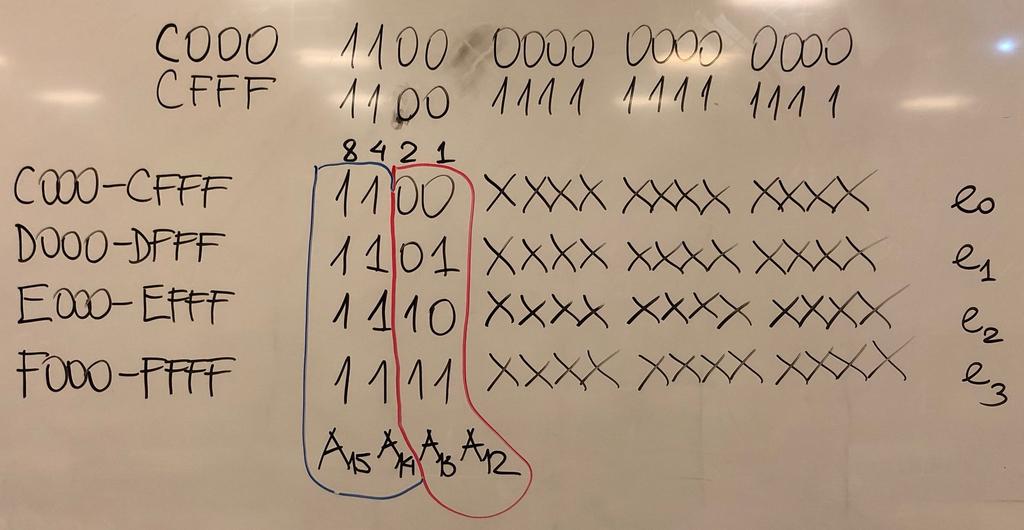
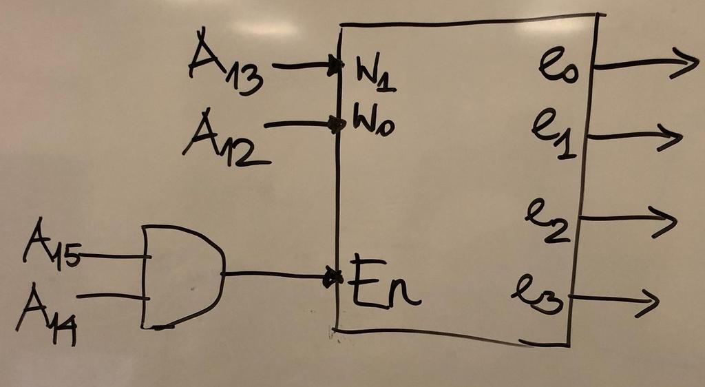
40 Problem Show how to implement a decoder that recognizes the following 4 ranges of a 6-bit address A, and generates the corresponding enable signals e,e,e2,e3: For A in: C-CFFF: D-DFFF: E-EFFF: F-FFFF: Assert e e e2 e3
41
42
43 Demultiplexers log 2 n selection inputs input n outputs Demultiplexer binary input n binary outputs log 2 n binary selection inputs Function: places input onto one of n outputs, with the remaining outputs asserted low Called -to-n demultiplexer Closely related to decoder Can build -to-n demultiplexer from log 2 n-to-n decoder by using the decoder's enable signal as the demultiplexer's input signal, and using decoder's input signals as the demultiplexer's selection input signals. 43
44 -to-4 Demultiplexer 44
45 Problem 2 How many inputs does an encoder with two data outputs have? How many inputs does an encoder with n data outputs have?
46 Encoders 2 n inputs w 2 n w y y n n outputs Encoder 2 n binary inputs n binary outputs Function: encodes information into an n-bit code Called 2 n -to-n encoder Can consider 2 n binary inputs as a single 2 n -bit input Can consider n binary output as a single n-bit output Encoders only work when exactly one binary input is equal to 46
47 4-to-2 Encoder w 3 w 2 w w y y (a) Truth table w w y w 2 w 3 y (b) Circuit 47
48 Problem 3 What is a difference between encoder and priority encoder?
49 Priority Encoders 2 n inputs w 2 n w y n n outputs y z "valid" output Priority Encoder 2 n binary inputs n binary outputs binary "valid" output Function: encodes information into an n-bit code based on priority of inputs Called 2 n -to-n priority encoder Priority encoder allows for multiple inputs to have a value of '', as it encodes the input with the highest priority (e.g., MSB = highest priority, LSB = lowest priority) "valid" output indicates when priority encoder output is valid Priority encoder is more common than an encoder 49
50 5 4-to-2 MSB Priority Encoder - w y - y z w - - w 2 - w 3
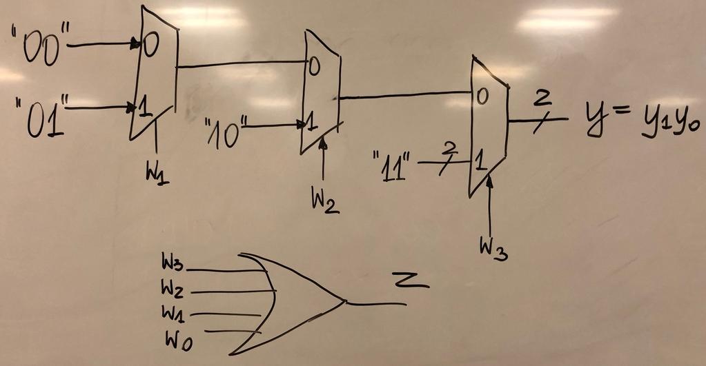
51 Problem 4 Show how to implement a 4-to-2 MSB Priority Encoder using multiplexers and a minimum number of logic gates
52
53 Problem 5 What is the width of an output of a 4x4 unsigned multiplier? What is the width of an output of a 4x4 signed multiplier? What is the width of an output of a NxN unsigned multiplier?
54 4x4-bit Unsigned Multiplier 4 4 a * c b U 8 54
55 4x4-bit Signed Multiplier 4 4 a * c b S 8 55
56 Problem 6 What is the width of an output of a 4x8 unsigned multiplier? What is the width of an output of a 4x8 signed multiplier? What is the width of an output of a NxM unsigned multiplier?
57 Problem 7 Give an example of binary inputs to an unsigned 4x4 multiplier and a signed 4x4 multiplier that produce different results.
58 Unsigned vs. Signed Multiplication Unsigned Signed 5 - x x 5 x x
59 Problem 8 Explain the difference between logic shift right and arithmetic shift right What arithmetic operations these shifts correspond to?
60 Logical Shift Right A >> C 4 4 L A(3) A(2) A() A() A(3) A(2) A() A C 6
61 Arithmetic Shift Right A >> C 4 4 A A(3) A(2) A() A() A C A(3) A(3) A(2) A() 6
62 Fixed Rotation A 4 <<< A(3) A(2) A() A() A C 4 C A(2) A() A() A(3) 62
63 8-bit Variable Rotator Left A 8 3 B A <<< B C 8 63
64 Problem 9 Explain using simple diagrams (based on medium-scale logic components) how to efficiently perform the following operations in hardware using combinational logic only A. C = A <<< 3 B. C = A <<< B, where A and C are 6-bit variables and B is a 4-bit variable
65 Fixed rotation C = A <<< 3 a(5) a(4) a(3) a(2) a() a() a(9) a(8) a(7) a(6) a(5) a(4) a(3) a(2) a() a() <<< 3 a(2) a() a() a(9) a(8) a(7) a(6) a(5) a(4) a(3) a(2) a() a() a(5) a(4) a(3) 65
66 Variable rotation C = A <<< B
ECE 545 Digital System Design with VHDL Lecture 1. Digital Logic Refresher Part A Combinational Logic Building Blocks
 ECE 545 Digital System Design with VHDL Lecture Digital Logic Refresher Part A Combinational Logic Building Blocks Lecture Roadmap Combinational Logic Basic Logic Review Basic Gates De Morgan s Law Combinational
XOR - XNOR Gates. The graphic symbol and truth table of XOR gate is shown in the figure.
 XOR - XNOR Gates Lesson Objectives: In addition to AND, OR, NOT, NAND and NOR gates, exclusive-or (XOR) and exclusive-nor (XNOR) gates are also used in the design of digital circuits. These have special
Lecture 2 Review on Digital Logic (Part 1)
") Lecture 2 Review on Digital Logic (Part 1) Xuan Silvia Zhang Washington University in St. Louis http://classes.engineering.wustl.edu/ese461/ Grading Engagement 5% Review Quiz 10% Homework 10% Labs 40%
Lecture 2 Review on Digital Logic (Part 1) Xuan Silvia Zhang Washington University in St. Louis http://classes.engineering.wustl.edu/ese461/ Grading Engagement 5% Review Quiz 10% Homework 10% Labs 40%
Combinational Logic. By : Ali Mustafa
 Combinational Logic By : Ali Mustafa Contents Adder Subtractor Multiplier Comparator Decoder Encoder Multiplexer How to Analyze any combinational circuit like this? Analysis Procedure To obtain the output
CprE 281: Digital Logic
 CprE 28: Digital Logic Instructor: Alexander Stoytchev http://www.ece.iastate.edu/~alexs/classes/ Decoders and Encoders CprE 28: Digital Logic Iowa State University, Ames, IA Copyright Alexander Stoytchev
BOOLEAN ALGEBRA. Introduction. 1854: Logical algebra was published by George Boole known today as Boolean Algebra
 BOOLEAN ALGEBRA Introduction 1854: Logical algebra was published by George Boole known today as Boolean Algebra It s a convenient way and systematic way of expressing and analyzing the operation of logic
Fundamentals of Digital Design
 Fundamentals of Digital Design Digital Radiation Measurement and Spectroscopy NE/RHP 537 1 Binary Number System The binary numeral system, or base-2 number system, is a numeral system that represents numeric
Combinational Logic. Lan-Da Van ( 范倫達 ), Ph. D. Department of Computer Science National Chiao Tung University Taiwan, R.O.C.
, Ph. D. Department of Computer Science National Chiao Tung University Taiwan, R.O.C.") Combinational Logic ( 范倫達 ), Ph. D. Department of Computer Science National Chiao Tung University Taiwan, R.O.C. Fall, 2017 ldvan@cs.nctu.edu.tw http://www.cs.nctu.edu.tw/~ldvan/ Combinational Circuits
Combinational Logic ( 范倫達 ), Ph. D. Department of Computer Science National Chiao Tung University Taiwan, R.O.C. Fall, 2017 ldvan@cs.nctu.edu.tw http://www.cs.nctu.edu.tw/~ldvan/ Combinational Circuits
Number System. Decimal to binary Binary to Decimal Binary to octal Binary to hexadecimal Hexadecimal to binary Octal to binary
 Number System Decimal to binary Binary to Decimal Binary to octal Binary to hexadecimal Hexadecimal to binary Octal to binary BOOLEAN ALGEBRA BOOLEAN LOGIC OPERATIONS Logical AND Logical OR Logical COMPLEMENTATION
Boolean Algebra, Gates and Circuits
 Boolean Algebra, Gates and Circuits Kasper Brink November 21, 2017 (Images taken from Tanenbaum, Structured Computer Organization, Fifth Edition, (c) 2006 Pearson Education, Inc.) Outline Last week: Von
Logic Design. Chapter 2: Introduction to Logic Circuits
 Logic Design Chapter 2: Introduction to Logic Circuits Introduction Logic circuits perform operation on digital signal Digital signal: signal values are restricted to a few discrete values Binary logic
COSC 243. Introduction to Logic And Combinatorial Logic. Lecture 4 - Introduction to Logic and Combinatorial Logic. COSC 243 (Computer Architecture)
") COSC 243 Introduction to Logic And Combinatorial Logic 1 Overview This Lecture Introduction to Digital Logic Gates Boolean algebra Combinatorial Logic Source: Chapter 11 (10 th edition) Source: J.R. Gregg,
COSC 243 Introduction to Logic And Combinatorial Logic 1 Overview This Lecture Introduction to Digital Logic Gates Boolean algebra Combinatorial Logic Source: Chapter 11 (10 th edition) Source: J.R. Gregg,
Digital Logic Design ENEE x. Lecture 14
 Digital Logic Design ENEE 244-010x Lecture 14 Announcements Homework 6 due today Agenda Last time: Binary Adders and Subtracters (5.1, 5.1.1) Carry Lookahead Adders (5.1.2, 5.1.3) This time: Decimal Adders
Chapter 4. Combinational: Circuits with logic gates whose outputs depend on the present combination of the inputs. elements. Dr.
 Chapter 4 Dr. Panos Nasiopoulos Combinational: Circuits with logic gates whose outputs depend on the present combination of the inputs. Sequential: In addition, they include storage elements Combinational
CHAPTER1: Digital Logic Circuits Combination Circuits
 CS224: Computer Organization S.KHABET CHAPTER1: Digital Logic Circuits Combination Circuits 1 PRIMITIVE LOGIC GATES Each of our basic operations can be implemented in hardware using a primitive logic gate.
Chapter 2 Combinational Logic Circuits
 Logic and Computer Design Fundamentals Chapter 2 Combinational Logic Circuits Part 1 Gate Circuits and Boolean Equations Chapter 2 - Part 1 2 Chapter 2 - Part 1 3 Chapter 2 - Part 1 4 Chapter 2 - Part
Discrete Mathematics. CS204: Spring, Jong C. Park Computer Science Department KAIST
 Discrete Mathematics CS204: Spring, 2008 Jong C. Park Computer Science Department KAIST Today s Topics Combinatorial Circuits Properties of Combinatorial Circuits Boolean Algebras Boolean Functions and
UNIVERSITI TENAGA NASIONAL. College of Information Technology
 UNIVERSITI TENAGA NASIONAL College of Information Technology BACHELOR OF COMPUTER SCIENCE (HONS.) FINAL EXAMINATION SEMESTER 2 2012/2013 DIGITAL SYSTEMS DESIGN (CSNB163) January 2013 Time allowed: 3 hours
Introduction to Digital Logic Missouri S&T University CPE 2210 Boolean Algebra
 Introduction to Digital Logic Missouri S&T University CPE 2210 Boolean Algebra Egemen K. Çetinkaya Egemen K. Çetinkaya Department of Electrical & Computer Engineering Missouri University of Science and
Slide Set 3. for ENEL 353 Fall Steve Norman, PhD, PEng. Electrical & Computer Engineering Schulich School of Engineering University of Calgary
 Slide Set 3 for ENEL 353 Fall 2016 Steve Norman, PhD, PEng Electrical & Computer Engineering Schulich School of Engineering University of Calgary Fall Term, 2016 SN s ENEL 353 Fall 2016 Slide Set 3 slide
CprE 281: Digital Logic
 CprE 28: Digital Logic Instructor: Alexander Stoytchev http://www.ece.iastate.edu/~alexs/classes/ Code Converters CprE 28: Digital Logic Iowa State University, Ames, IA Copyright Alexander Stoytchev HW
Digital System Design Combinational Logic. Assoc. Prof. Pradondet Nilagupta
 Digital System Design Combinational Logic Assoc. Prof. Pradondet Nilagupta pom@ku.ac.th Acknowledgement This lecture note is modified from Engin112: Digital Design by Prof. Maciej Ciesielski, Prof. Tilman
CSC9R6 Computer Design. Practical Digital Logic
 CSC9R6 Computer Design Practical Digital Logic 1 References (for this part of CSC9R6) Hamacher et al: Computer Organization App A. In library Floyd: Digital Fundamentals Ch 1, 3-6, 8-10 web page: www.prenhall.com/floyd/
Class Website:
 ECE 20B, Winter 2003 Introduction to Electrical Engineering, II LECTURE NOTES #5 Instructor: Andrew B. Kahng (lecture) Email: abk@ece.ucsd.edu Telephone: 858-822-4884 office, 858-353-0550 cell Office:
Circuits & Boolean algebra.
 Circuits & Boolean algebra http://xkcd.com/730/ CSCI 255: Introduction to Embedded Systems Keith Vertanen Copyright 2011 Digital circuits Overview How a switch works Building basic gates from switches
ELCT201: DIGITAL LOGIC DESIGN
 ELCT201: DIGITAL LOGIC DESIGN Dr. Eng. Haitham Omran, haitham.omran@guc.edu.eg Dr. Eng. Wassim Alexan, wassim.joseph@guc.edu.eg Lecture 5 Following the slides of Dr. Ahmed H. Madian ذو الحجة 1438 ه Winter
Boolean algebra. Examples of these individual laws of Boolean, rules and theorems for Boolean algebra are given in the following table.
 The Laws of Boolean Boolean algebra As well as the logic symbols 0 and 1 being used to represent a digital input or output, we can also use them as constants for a permanently Open or Closed circuit or
Switches: basic element of physical implementations
 Combinational logic Switches Basic logic and truth tables Logic functions Boolean algebra Proofs by re-writing and by perfect induction Winter 200 CSE370 - II - Boolean Algebra Switches: basic element
Combinational Logic. Lan-Da Van ( 范倫達 ), Ph. D. Department of Computer Science National Chiao Tung University Taiwan, R.O.C.
, Ph. D. Department of Computer Science National Chiao Tung University Taiwan, R.O.C.") Combinational Logic ( 范倫達 ), Ph. D. Department of Computer Science National Chiao Tung University Taiwan, R.O.C. Fall, 2010 ldvan@cs.nctu.edu.tw http://www.cs.nctu.edu.tw/~ldvan/ Combinational Circuits
Combinational Logic ( 范倫達 ), Ph. D. Department of Computer Science National Chiao Tung University Taiwan, R.O.C. Fall, 2010 ldvan@cs.nctu.edu.tw http://www.cs.nctu.edu.tw/~ldvan/ Combinational Circuits
CS 226: Digital Logic Design
 CS 226: Digital Logic Design 0 1 1 I S 0 1 0 S Department of Computer Science and Engineering, Indian Institute of Technology Bombay. 1 of 29 Objectives In this lecture we will introduce: 1. Logic functions
ELCT201: DIGITAL LOGIC DESIGN
 ELCT2: DIGITAL LOGIC DESIGN Dr. Eng. Haitham Omran, haitham.omran@guc.edu.eg Dr. Eng. Wassim Alexan, wassim.joseph@guc.edu.eg Lecture 4 Following the slides of Dr. Ahmed H. Madian محرم 439 ه Winter 28
Combinational Logic. Review of Combinational Logic 1
 Combinational Logic! Switches -> Boolean algebra! Representation of Boolean functions! Logic circuit elements - logic gates! Regular logic structures! Timing behavior of combinational logic! HDLs and combinational
COMBINATIONAL LOGIC CIRCUITS. Dr. Mudathir A. Fagiri
 COMBINATIONAL LOGIC CIRCUITS Dr. Mudathir A. Fagiri Standard Combinational Modules Decoder: Decode address Encoder: Encode address Multiplexer (Mux): Select data by address Demultiplexier (DeMux): Direct
EECS150 - Digital Design Lecture 4 - Boolean Algebra I (Representations of Combinational Logic Circuits)
") EECS150 - Digital Design Lecture 4 - Boolean Algebra I (Representations of Combinational Logic Circuits) September 5, 2002 John Wawrzynek Fall 2002 EECS150 Lec4-bool1 Page 1, 9/5 9am Outline Review of
EECS150 - Digital Design Lecture 4 - Boolean Algebra I (Representations of Combinational Logic Circuits) September 5, 2002 John Wawrzynek Fall 2002 EECS150 Lec4-bool1 Page 1, 9/5 9am Outline Review of
Outline. EECS150 - Digital Design Lecture 4 - Boolean Algebra I (Representations of Combinational Logic Circuits) Combinational Logic (CL) Defined
 Combinational Logic (CL) Defined") EECS150 - Digital Design Lecture 4 - Boolean Algebra I (Representations of Combinational Logic Circuits) January 30, 2003 John Wawrzynek Outline Review of three representations for combinational logic:
EECS150 - Digital Design Lecture 4 - Boolean Algebra I (Representations of Combinational Logic Circuits) January 30, 2003 John Wawrzynek Outline Review of three representations for combinational logic:
Week-I. Combinational Logic & Circuits
 Week-I Combinational Logic & Circuits Overview Binary logic operations and gates Switching algebra Algebraic Minimization Standard forms Karnaugh Map Minimization Other logic operators IC families and
Design of Sequential Circuits
 Design of Sequential Circuits Seven Steps: Construct a state diagram (showing contents of flip flop and inputs with next state) Assign letter variables to each flip flop and each input and output variable
 vidyarthiplus.com vidyarthiplus.com vidyarthiplus.com ANNA UNIVERSITY- COMBATORE B.E./ B.TECH. DEGREE EXAMINATION - JUNE 2009. ELECTRICAL & ELECTONICS ENGG. - FOURTH SEMESTER DIGITAL LOGIC CIRCUITS PART-A
Chap 2. Combinational Logic Circuits
 Overview 2 Chap 2. Combinational Logic Circuits Spring 24 Part Gate Circuits and Boolean Equations Binary Logic and Gates Boolean Algebra Standard Forms Part 2 Circuit Optimization Two-Level Optimization
Number System conversions
 Number System conversions Number Systems The system used to count discrete units is called number system. There are four systems of arithmetic which are often used in digital electronics. Decimal Number
Chapter 2 Boolean Algebra and Logic Gates
 Chapter 2 Boolean Algebra and Logic Gates Huntington Postulates 1. (a) Closure w.r.t. +. (b) Closure w.r.t.. 2. (a) Identity element 0 w.r.t. +. x + 0 = 0 + x = x. (b) Identity element 1 w.r.t.. x 1 =
Introduction to Digital Logic Missouri S&T University CPE 2210 Combinatorial Circuit Analysis and Synthesis
 Introduction to Digital Logic Missouri S&T University CPE 2210 Combinatorial Circuit Analysis and Synthesis Egemen K. Çetinkaya Department of Electrical & Computer Engineering Missouri University of Science
Lecture A: Logic Design and Gates
 Lecture A: Logic Design and Gates Syllabus My office hours 9.15-10.35am T,Th or gchoi@ece.tamu.edu 333G WERC Text: Brown and Vranesic Fundamentals of Digital Logic,» Buy it.. Or borrow it» Other book:
KP/Worksheets: Propositional Logic, Boolean Algebra and Computer Hardware Page 1 of 8
 KP/Worksheets: Propositional Logic, Boolean Algebra and Computer Hardware Page 1 of 8 Q1. What is a Proposition? Q2. What are Simple and Compound Propositions? Q3. What is a Connective? Q4. What are Sentential
CSE 140 Lecture 11 Standard Combinational Modules. CK Cheng and Diba Mirza CSE Dept. UC San Diego
 CSE 4 Lecture Standard Combinational Modules CK Cheng and Diba Mirza CSE Dept. UC San Diego Part III - Standard Combinational Modules (Harris: 2.8, 5) Signal Transport Decoder: Decode address Encoder:
Digital Logic: Boolean Algebra and Gates. Textbook Chapter 3
 Digital Logic: Boolean Algebra and Gates Textbook Chapter 3 Basic Logic Gates XOR CMPE12 Summer 2009 02-2 Truth Table The most basic representation of a logic function Lists the output for all possible
MC9211 Computer Organization
 MC92 Computer Organization Unit : Digital Fundamentals Lesson2 : Boolean Algebra and Simplification (KSB) (MCA) (29-2/ODD) (29 - / A&B) Coverage Lesson2 Introduces the basic postulates of Boolean Algebra
2009 Spring CS211 Digital Systems & Lab CHAPTER 2: INTRODUCTION TO LOGIC CIRCUITS
 CHAPTER 2: INTRODUCTION TO LOGIC CIRCUITS What will we learn? 2 Logic functions and circuits Boolean Algebra Logic gates and Synthesis CAD tools and VHDL Read Section 2.9 and 2.0 Terminology 3 Digital
Logic. Combinational. inputs. outputs. the result. system can
 Digital Electronics Combinational Logic Functions Digital logic circuits can be classified as either combinational or sequential circuits. A combinational circuit is one where the output at any time depends
Chapter 2: Switching Algebra and Logic Circuits
 Chapter 2: Switching Algebra and Logic Circuits Formal Foundation of Digital Design In 1854 George Boole published An investigation into the Laws of Thoughts Algebraic system with two values 0 and 1 Used
DIGITAL CIRCUIT LOGIC BOOLEAN ALGEBRA (CONT.)
") DIGITAL CIRCUIT LOGIC BOOLEAN ALGEBRA (CONT.) 1 Learning Objectives 1. Apply the laws and theorems of Boolean algebra to to the manipulation of algebraic expressions to simplifying an expression, finding
DIGITAL CIRCUIT LOGIC BOOLEAN ALGEBRA (CONT.) 1 Learning Objectives 1. Apply the laws and theorems of Boolean algebra to to the manipulation of algebraic expressions to simplifying an expression, finding
EEE130 Digital Electronics I Lecture #4
 EEE130 Digital Electronics I Lecture #4 - Boolean Algebra and Logic Simplification - By Dr. Shahrel A. Suandi Topics to be discussed 4-1 Boolean Operations and Expressions 4-2 Laws and Rules of Boolean
Systems I: Computer Organization and Architecture
 Systems I: Computer Organization and Architecture Lecture 6 - Combinational Logic Introduction A combinational circuit consists of input variables, logic gates, and output variables. The logic gates accept
Logic and Boolean algebra
 Computer Mathematics Week 7 Logic and Boolean algebra College of Information Science and Engineering Ritsumeikan University last week coding theory channel coding information theory concept Hamming distance
XI STANDARD [ COMPUTER SCIENCE ] 5 MARKS STUDY MATERIAL.
![XI STANDARD [ COMPUTER SCIENCE ] 5 MARKS STUDY MATERIAL.](/thumbs/81/84726747.jpg "XI STANDARD [ COMPUTER SCIENCE ] 5 MARKS STUDY MATERIAL.") 2017-18 XI STANDARD [ COMPUTER SCIENCE ] 5 MARKS STUDY MATERIAL HALF ADDER 1. The circuit that performs addition within the Arithmetic and Logic Unit of the CPU are called adders. 2. A unit that adds two
2017-18 XI STANDARD [ COMPUTER SCIENCE ] 5 MARKS STUDY MATERIAL HALF ADDER 1. The circuit that performs addition within the Arithmetic and Logic Unit of the CPU are called adders. 2. A unit that adds two
Digital Logic (2) Boolean Algebra
 Boolean Algebra") Digital Logic (2) Boolean Algebra Boolean algebra is the mathematics of digital systems. It was developed in 1850 s by George Boole. We will use Boolean algebra to minimize logic expressions. Karnaugh
Digital Logic (2) Boolean Algebra Boolean algebra is the mathematics of digital systems. It was developed in 1850 s by George Boole. We will use Boolean algebra to minimize logic expressions. Karnaugh
Additional Gates COE 202. Digital Logic Design. Dr. Muhamed Mudawar King Fahd University of Petroleum and Minerals
 Additional Gates COE 202 Digital Logic Design Dr. Muhamed Mudawar King Fahd University of Petroleum and Minerals Presentation Outline Additional Gates and Symbols Universality of NAND and NOR gates NAND-NAND
Review: Additional Boolean operations
 Review: Additional Boolean operations Operation: NAND (NOT-AND) NOR (NOT-OR) XOR (exclusive OR) Expressions: (xy) = x + y (x + y) = x y x y = x y + xy Truth table: x y (xy) x y (x+y) x y x y 0 0 1 0 1
MODULAR CIRCUITS CHAPTER 7
 CHAPTER 7 MODULAR CIRCUITS A modular circuit is a digital circuit that performs a specific function or has certain usage. The modular circuits to be introduced in this chapter are decoders, encoders, multiplexers,
CS61c: Representations of Combinational Logic Circuits
 CS61c: Representations of Combinational Logic Circuits J. Wawrzynek March 5, 2003 1 Introduction Recall that synchronous systems are composed of two basic types of circuits, combination logic circuits,
CMSC 313 Lecture 17. Focus Groups. Announcement: in-class lab Thu 10/30 Homework 3 Questions Circuits for Addition Midterm Exam returned
 Focus Groups CMSC 33 Lecture 7 Need good sample of all types of CS students Mon /7 & Thu /2, 2:3p-2:p & 6:p-7:3p Announcement: in-class lab Thu /3 Homework 3 Questions Circuits for Addition Midterm Exam
Logic Gates and Boolean Algebra
 Logic Gates and oolean lgebra The ridge etween Symbolic Logic nd Electronic Digital Computing Compiled y: Muzammil hmad Khan mukhan@ssuet.edu.pk asic Logic Functions and or nand nor xor xnor not 2 Logic
ELCT201: DIGITAL LOGIC DESIGN
 ELCT2: DIGITAL LOGIC DESIGN Dr. Eng. Haitham Omran, haitham.omran@guc.edu.eg Dr. Eng. Wassim Alexan, wassim.joseph@guc.edu.eg Lecture 2 Following the slides of Dr. Ahmed H. Madian ذو الحجة 438 ه Winter
Chapter 2 (Lect 2) Canonical and Standard Forms. Standard Form. Other Logic Operators Logic Gates. Sum of Minterms Product of Maxterms
 Canonical and Standard Forms. Standard Form. Other Logic Operators Logic Gates. Sum of Minterms Product of Maxterms") Chapter 2 (Lect 2) Canonical and Standard Forms Sum of Minterms Product of Maxterms Standard Form Sum of products Product of sums Other Logic Operators Logic Gates Basic and Multiple Inputs Positive and
Chapter 2 (Lect 2) Canonical and Standard Forms Sum of Minterms Product of Maxterms Standard Form Sum of products Product of sums Other Logic Operators Logic Gates Basic and Multiple Inputs Positive and
Hardware Design I Chap. 4 Representative combinational logic
 Hardware Design I Chap. 4 Representative combinational logic E-mail: shimada@is.naist.jp Already optimized circuits There are many optimized circuits which are well used You can reduce your design workload
University of Toronto Faculty of Applied Science and Engineering Final Examination
 University of Toronto Faculty of Applied Science and Engineering Final Examination ECE 24S - Digital Systems Examiner: Belinda Wang, Jianwen Zhu 2: - 4:3pm, April 26th, 24 Duration: 5 minutes (2.5 hours)
CS 121 Digital Logic Design. Chapter 2. Teacher Assistant. Hanin Abdulrahman
 CS 121 Digital Logic Design Chapter 2 Teacher Assistant Hanin Abdulrahman 1 2 Outline 2.2 Basic Definitions 2.3 Axiomatic Definition of Boolean Algebra. 2.4 Basic Theorems and Properties 2.5 Boolean Functions
Combinational Logic Design Combinational Functions and Circuits
 Combinational Logic Design Combinational Functions and Circuits Overview Combinational Circuits Design Procedure Generic Example Example with don t cares: BCD-to-SevenSegment converter Binary Decoders
LOGIC GATES. Basic Experiment and Design of Electronics. Ho Kyung Kim, Ph.D.
 Basic Eperiment and Design of Electronics LOGIC GATES Ho Kyung Kim, Ph.D. hokyung@pusan.ac.kr School of Mechanical Engineering Pusan National University Outline Boolean algebra Logic gates Karnaugh maps
Sample Test Paper - I
 Scheme G Sample Test Paper - I Course Name : Computer Engineering Group Marks : 25 Hours: 1 Hrs. Q.1) Attempt any THREE: 09 Marks a) Define i) Propagation delay ii) Fan-in iii) Fan-out b) Convert the following:
Boolean Algebra & Logic Gates. By : Ali Mustafa
 Boolean Algebra & Logic Gates By : Ali Mustafa Digital Logic Gates There are three fundamental logical operations, from which all other functions, no matter how complex, can be derived. These Basic functions
Boolean Algebra. Philipp Koehn. 9 September 2016
 Boolean Algebra Philipp Koehn 9 September 2016 Core Boolean Operators 1 AND OR NOT A B A and B 0 0 0 0 1 0 1 0 0 1 1 1 A B A or B 0 0 0 0 1 1 1 0 1 1 1 1 A not A 0 1 1 0 AND OR NOT 2 Boolean algebra Boolean
E&CE 223 Digital Circuits & Systems. Lecture Transparencies (Boolean Algebra & Logic Gates) M. Sachdev
 M. Sachdev") E&CE 223 Digital Circuits & Systems Lecture Transparencies (Boolean Algebra & Logic Gates) M. Sachdev 4 of 92 Section 2: Boolean Algebra & Logic Gates Major topics Boolean algebra NAND & NOR gates Boolean
E&CE 223 Digital Circuits & Systems Lecture Transparencies (Boolean Algebra & Logic Gates) M. Sachdev 4 of 92 Section 2: Boolean Algebra & Logic Gates Major topics Boolean algebra NAND & NOR gates Boolean
Boolean Algebra and Digital Logic 2009, University of Colombo School of Computing
 IT 204 Section 3.0 Boolean Algebra and Digital Logic Boolean Algebra 2 Logic Equations to Truth Tables X = A. B + A. B + AB A B X 0 0 0 0 3 Sum of Products The OR operation performed on the products of
UC Berkeley College of Engineering, EECS Department CS61C: Representations of Combinational Logic Circuits
 2 Wawrzynek, Garcia 2004 c UCB UC Berkeley College of Engineering, EECS Department CS61C: Representations of Combinational Logic Circuits 1 Introduction Original document by J. Wawrzynek (2003-11-15) Revised
Experiment 7: Magnitude comparators
 Module: Logic Design Lab Name:... University no:.. Group no: Lab Partner Name: Experiment 7: Magnitude comparators Mr. Mohamed El-Saied Objective: Realization of -bit comparator using logic gates. Realization
EC-121 Digital Logic Design
 EC-121 Digital Logic Design Lecture 2 [Updated on 02-04-18] Boolean Algebra and Logic Gates Dr Hashim Ali Spring 2018 Department of Computer Science and Engineering HITEC University Taxila!1 Overview What
Combinational Logic. Mantıksal Tasarım BBM231. section instructor: Ufuk Çelikcan
 Combinational Logic Mantıksal Tasarım BBM23 section instructor: Ufuk Çelikcan Classification. Combinational no memory outputs depends on only the present inputs expressed by Boolean functions 2. Sequential
Total Time = 90 Minutes, Total Marks = 50. Total /50 /10 /18
 University of Waterloo Department of Electrical & Computer Engineering E&CE 223 Digital Circuits and Systems Midterm Examination Instructor: M. Sachdev October 23rd, 2007 Total Time = 90 Minutes, Total
UNIVERSITY OF CALIFORNIA, RIVERSIDE
 Final Page of UNIVERITY OF CLIFORNI, RIVERIDE Computer cience Department and Electrical Engineering Department C/EE20 Logic Design Final December, 2000 50 Name: olution Key tudent ID#: Please print legibly
Introduction to Digital Logic Missouri S&T University CPE 2210 Boolean Representations
 Introduction to Digital Logic Missouri S&T University CPE 2210 Egemen K. Çetinkaya Egemen K. Çetinkaya Department of Electrical & Computer Engineering Missouri University of Science and Technology cetinkayae@mst.edu
Slides for Lecture 19
 Slides for Lecture 19 ENEL 353: Digital Circuits Fall 2013 Term Steve Norman, PhD, PEng Electrical & Computer Engineering Schulich School of Engineering University of Calgary 23 October, 2013 ENEL 353
DIGITAL CIRCUIT LOGIC BOOLEAN ALGEBRA
 DIGITAL CIRCUIT LOGIC BOOLEAN ALGEBRA 1 Learning Objectives Understand the basic operations and laws of Boolean algebra. Relate these operations and laws to circuits composed of AND gates, OR gates, INVERTERS
ENGIN 112 Intro to Electrical and Computer Engineering
 ENGIN 112 Intro to Electrical and Computer Engineering Lecture 17 Encoders and Decoders Overview Binary decoders Converts an n-bit code to a single active output Can be developed using AND/OR gates Can
Chapter 5. Digital systems. 5.1 Boolean algebra Negation, conjunction and disjunction
 Chapter 5 igital systems digital system is any machine that processes information encoded in the form of digits. Modern digital systems use binary digits, encoded as voltage levels. Two voltage levels,
Introduction to Digital Logic Missouri S&T University CPE 2210 Subtractors
 Introduction to Digital Logic Missouri S&T University CPE 2210 Egemen K. Çetinkaya Egemen K. Çetinkaya Department of Electrical & Computer Engineering Missouri University of Science and Technology cetinkayae@mst.edu
COSC3330 Computer Architecture Lecture 2. Combinational Logic
 COSC333 Computer rchitecture Lecture 2. Combinational Logic Instructor: Weidong Shi (Larry), PhD Computer Science Department University of Houston Today Combinational Logic oolean lgebra Mux, DeMux, Decoder
Digital Logic. Lecture 5 - Chapter 2. Outline. Other Logic Gates and their uses. Other Logic Operations. CS 2420 Husain Gholoom - lecturer Page 1
 Lecture 5 - Chapter 2 Outline Other Logic Gates and their uses Other Logic Operations CS 2420 Husain Gholoom - lecturer Page 1 Digital logic gates CS 2420 Husain Gholoom - lecturer Page 2 Buffer A buffer
Total Time = 90 Minutes, Total Marks = 100. Total /10 /25 /20 /10 /15 /20
 University of Waterloo Department of Electrical & Computer Engineering E&CE 223 Digital Circuits and Systems Midterm Examination Instructor: M. Sachdev October 30th, 2006 Total Time = 90 Minutes, Total
Unit 8A Computer Organization. Boolean Logic and Gates
 Unit 8A Computer Organization Boolean Logic and Gates Announcements Bring ear buds or headphones to lab! 15110 Principles of Computing, Carnegie Mellon University - CORTINA 2 Representing and Manipulating
Digital Circuit And Logic Design I. Lecture 3
 Digital Circuit And Logic Design I Lecture 3 Outline Combinational Logic Design Principles (). Introduction 2. Switching algebra 3. Combinational-circuit analysis 4. Combinational-circuit synthesis Panupong
1.10 (a) Function of AND, OR, NOT, NAND & NOR Logic gates and their input/output.
 Function of AND, OR, NOT, NAND & NOR Logic gates and their input/output.") Chapter 1.10 Logic Gates 1.10 (a) Function of AND, OR, NOT, NAND & NOR Logic gates and their input/output. Microprocessors are the central hardware that runs computers. There are several components that
Chapter 1.10 Logic Gates 1.10 (a) Function of AND, OR, NOT, NAND & NOR Logic gates and their input/output. Microprocessors are the central hardware that runs computers. There are several components that
4 Switching Algebra 4.1 Axioms; Signals and Switching Algebra
 4 Switching Algebra 4.1 Axioms; Signals and Switching Algebra To design a digital circuit that will perform a required function, it is necessary to manipulate and combine the various input signals in certain
COMBINATIONAL LOGIC FUNCTIONS
 COMBINATIONAL LOGIC FUNCTIONS Digital logic circuits can be classified as either combinational or sequential circuits. A combinational circuit is one where the output at any time depends only on the present
Logic and Computer Design Fundamentals. Chapter 5 Arithmetic Functions and Circuits
 Logic and Computer Design Fundamentals Chapter 5 Arithmetic Functions and Circuits Arithmetic functions Operate on binary vectors Use the same subfunction in each bit position Can design functional block
Chapter 2 Combinational Logic Circuits
 Logic and Computer Design Fundamentals Chapter 2 Combinational Logic Circuits Part 3 Additional Gates and Circuits Charles Kime & Thomas Kaminski 2008 Pearson Education, Inc. (Hyperlinks are active in
211: Computer Architecture Summer 2016
 211: Computer Architecture Summer 2016 Liu Liu Topic: Storage Project3 Digital Logic - Storage: Recap - Review: cache hit rate - Project3 - Digital Logic: - truth table => SOP - simplification: Boolean
ECE 250 / CPS 250 Computer Architecture. Basics of Logic Design Boolean Algebra, Logic Gates
 ECE 250 / CPS 250 Computer Architecture Basics of Logic Design Boolean Algebra, Logic Gates Benjamin Lee Slides based on those from Andrew Hilton (Duke), Alvy Lebeck (Duke) Benjamin Lee (Duke), and Amir
CMPE12 - Notes chapter 1. Digital Logic. (Textbook Chapter 3)
") CMPE12 - Notes chapter 1 Digital Logic (Textbook Chapter 3) Transistor: Building Block of Computers Microprocessors contain TONS of transistors Intel Montecito (2005): 1.72 billion Intel Pentium 4 (2000):
CMPE12 - Notes chapter 1 Digital Logic (Textbook Chapter 3) Transistor: Building Block of Computers Microprocessors contain TONS of transistors Intel Montecito (2005): 1.72 billion Intel Pentium 4 (2000):
SAMPLE ANSWERS MARKER COPY
 Page 1 of 12 School of Computer Science 60-265-01 Computer Architecture and Digital Design Fall 2012 Midterm Examination # 1 Tuesday, October 23, 2012 SAMPLE ANSWERS MARKER COPY Duration of examination: