3D Force Couple System and Resultant. Q.No.1: Replace the force system by an equivalent force and couple moment at point A.
|
|
|
- Catherine Moody
- 6 years ago
- Views:
Transcription

1 3D Force Couple System and Resultant Q.No.1: Replace the force system by an equivalent force and couple moment at point A. Q.No.2: Handle forces F1 and F2 are applied to the electric drill. Replace this force system by an equivalent resultant force and couple moment acting at point O. Express the results in Cartesian vector from.

2 Q.No.3 Replace the loading system by an equivalent resultant force and couple moment acting at point O. Q.No.4: The horizontal top of a concrete column is subjected to the system of forces shown. Represent the resultant of all forces as a force R at point O and a couple M. Also specify the magnitudes of R and M.

3 Q.No.5: The structure supports vertical forces F = 200 lb and P = 50 lb. Pipe segments BC and CD are parallel to the y and x axes, respectively. Determine the resultant moment of both forces about point O. Q.No.6: The turnbuckle is tightened until the tension in cable AB is 2.4 kn. Determine the moment about point O of the cable force acting on point A and the magnitude of this moment.
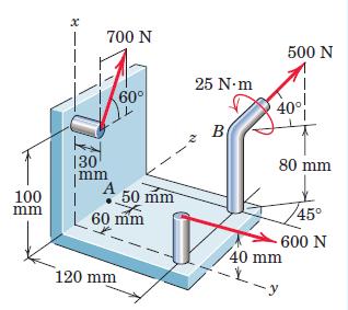
4 Q.No.7: Replace the loading system by an equivalent resultant force and couple moment acting at point O. Q.No.8: Replace the two wrenches and the force, acting on the pipe assembly, by an equivalent resultant force and couple moment at point O.

5 Q.No.9: Replace the two forces acting on the post by a resultant force and couple moment at point O. Express the results in Cartesian vector form. Q.No.10: The structural member is subjected to a couple moment M and forces F1 and F2 in Fig. Replace this system by an equivalent resultant force and couple moment acting at its base, point O.

6 Q.No.11: Calculate the combined moment of the couple C and the force P about the axis AB. Use C =80 N m and P =400 N. Q.No.12: Replace the force and the couple shown with an equivalent force-couple system where the force acts at A. Q.No.13: Two cable tensions and a couple act on the rod OAB. Determine the equivalent force-couple system with the force acting at O.
7 Q.No.14: Replace the two forces and one couple acting on the rigid pipe frame by their equivalent resultant force R acting at point O and a couple Mo Q.No.15: Replace the two forces and a couple acting on the bent rod ABC with an 100 N equivalent forcecouple system with the force acting at C. Q.No.16: Suppose that the tension in cable AB is 4 kn, and you want to adjust the tensions in cables AC and AD so that the sum of the moments about the origin O due to the forces exerted by the cables at point A is zero. Determine the tensions

8 Q.No.17: The force system consists of the force P= 300i + 200j + 150k N and the couple C. Determine the magnitude of C if the moment of this force system about the axis DE is 800 N m. Q.No.18: The combined action of the three forces on the base at O may be obtained by establishing their resultant through O. Determine the magnitudes of R and the accompanying couple M.


9 Q.No.19: A section of a piping system is acted on by the three couples shown in Fig. Determine the magnitude of the resultant couple-vector C R and its direction cosines, given that the magnitudes of the applied couples are C1 =50 N m, C2 =90 N m, and C3 =140 N m. Q.No.20: The right-angle pipe OAB of Prob. 2/111 is shown again here. Replace the 750-N tensile force which the cable exerts on point B by a force couple system at point O.

10 Q.No.21: Replace the two forces and the negative wrench by a single force R applied at A and the corresponding couple M. Q.No.22:The concrete slab supports the six vertical loads shown. Determine the x- and y-coordinates of the point on the slab through which the resultant of the loading system passes.


11 Q.No.22:The thin rectangular plate is subjected to the four forces shown. Determine the equivalent force couple system at O. Q.No.23:Determine the force couple system at O which is equivalent to the two forces applied to the shaft AOB. Is R perpendicular to Mo?


12 Q.No.24: Replace the two forces and single couple by an equivalent force couple system at point A. Q.No.25: Replace the two forces and single couple by an equivalent force couple system at point O.
13
14
Force Couple Systems = Reduction of a Force to an Equivalent Force and Moment (Moving a Force to Another Point) acting on a body has two effects:
 acting on a body has two effects:") ESULTANTS orce Couple Systems = eduction of a orce to an Equivalent orce and Moment (Moving a orce to Another Point) The force acting on a body has two effects: the first one is the tendency to push or
ESULTANTS orce Couple Systems = eduction of a orce to an Equivalent orce and Moment (Moving a orce to Another Point) The force acting on a body has two effects: the first one is the tendency to push or
TUTORIAL SHEET 1. magnitude of P and the values of ø and θ. Ans: ø =74 0 and θ= 53 0
 TUTORIAL SHEET 1 1. The rectangular platform is hinged at A and B and supported by a cable which passes over a frictionless hook at E. Knowing that the tension in the cable is 1349N, determine the moment
(counterclockwise - ccw)
") Problems (on oment) 1. The rod on the power control mechanism for a business jet is subjected to a force of 80 N. Determine the moment of this force about the bearing at. + 0.15sin 6080sin 00.15cos60 80
Problems (on oment) 1. The rod on the power control mechanism for a business jet is subjected to a force of 80 N. Determine the moment of this force about the bearing at. + 0.15sin 6080sin 00.15cos60 80
Eng Sample Test 4
 1. An adjustable tow bar connecting the tractor unit H with the landing gear J of a large aircraft is shown in the figure. Adjusting the height of the hook F at the end of the tow bar is accomplished by
Statics Chapter II Fall 2018 Exercises Corresponding to Sections 2.1, 2.2, and 2.3
 Statics Chapter II Fall 2018 Exercises Corresponding to Sections 2.1, 2.2, and 2.3 2 3 Determine the magnitude of the resultant force FR = F1 + F2 and its direction, measured counterclockwise from the
ARC241 Structural Analysis I Lecture 5, Sections ST4.5 ST4.10
 Lecture 5, Sections ST4.5 ST4.10 ST4.5) Moment of a Force about a Specified Axis ST4.6) Moment of a Couple ST4.7) Equivalent System ST4.8) Resultant of a Force and a Couple System ST4.9) Further Reduction
Unit 1. (a) tan α = (b) tan α = (c) tan α = (d) tan α =
 tan α = (b) tan α = (c) tan α = (d) tan α =") Unit 1 1. The subjects Engineering Mechanics deals with (a) Static (b) kinematics (c) Kinetics (d) All of the above 2. If the resultant of two forces P and Q is acting at an angle α with P, then (a) tan
Unit 1 1. The subjects Engineering Mechanics deals with (a) Static (b) kinematics (c) Kinetics (d) All of the above 2. If the resultant of two forces P and Q is acting at an angle α with P, then (a) tan
IDE 110 Mechanics of Materials Spring 2006 Final Examination FOR GRADING ONLY
 Spring 2006 Final Examination STUDENT S NAME (please print) STUDENT S SIGNATURE STUDENT NUMBER IDE 110 CLASS SECTION INSTRUCTOR S NAME Do not turn this page until instructed to start. Write your name on
EQUILIBRIUM OF RIGID BODIES
 EQUILIBRIUM OF RIGID BODIES Equilibrium A body in equilibrium is at rest or can translate with constant velocity F = 0 M = 0 EQUILIBRIUM IN TWO DIMENSIONS Case where the force system acting on a rigid
acting on a body has two effects:
 The force acting on a body has two effects: the first one is the tendency to push or pull the body in the direction of the force, and the second one is to rotate the body about any fixed axis which does
CHAPTER 2: EQUILIBRIUM OF RIGID BODIES
 For a rigid body to be in equilibrium, the net force as well as the net moment about any arbitrary point O must be zero Summation of all external forces. Equilibrium: Sum of moments of all external forces.
Chapter -4- Force System Resultant
 Ishik University / Sulaimani Civil Engineering Department Chapter -4- Force System Resultant 1 2 1 CHAPTER OBJECTIVES To discuss the concept of the moment of a force and show how to calculate it in two
MECE 3321 MECHANICS OF SOLIDS CHAPTER 1
 MECE 3321 MECHANICS O SOLIDS CHAPTER 1 Samantha Ramirez, MSE WHAT IS MECHANICS O MATERIALS? Rigid Bodies Statics Dynamics Mechanics Deformable Bodies Solids/Mech. Of Materials luids 1 WHAT IS MECHANICS
Purpose of this Guide: To thoroughly prepare students for the exact types of problems that will be on Exam 3.
 ES230 STRENGTH OF MTERILS Exam 3 Study Guide Exam 3: Wednesday, March 8 th in-class Updated 3/3/17 Purpose of this Guide: To thoroughly prepare students for the exact types of problems that will be on
PROBLEMS on FORCE SYSTEMS
 on FORCE SYSTEMS 1. The guy cables AB and AC are attached to the top of the transmission tower. The tension in cable AB is 8 kn. Determine the required tension T in cable AC such that the net effect of
1. The horizontal beam represented in Examination Figure 6 carries three loads P 1. and R 2
 Student ID: 52573847 Exam: 286037RR - Engineering Mechanics, Part 2 When you have completed your exam and reviewed your answers, click Submit Exam. Answers will not be recorded until you hit Submit Exam.
SOLUTION 8 7. To hold lever: a+ M O = 0; F B (0.15) - 5 = 0; F B = N. Require = N N B = N 0.3. Lever,
 - 5 = 0; F B = N. Require = N N B = N 0.3. Lever,") 8 3. If the coefficient of static friction at is m s = 0.4 and the collar at is smooth so it only exerts a horizontal force on the pipe, determine the minimum distance x so that the bracket can support
8 3. If the coefficient of static friction at is m s = 0.4 and the collar at is smooth so it only exerts a horizontal force on the pipe, determine the minimum distance x so that the bracket can support
Sample 5. Determine the tension in the cable and the horizontal and vertical components of reaction at the pin A. Neglect the size of the pulley.
 Sample 1 The tongs are designed to handle hot steel tubes which are being heat-treated in an oil bath. For a 20 jaw opening, what is the minimum coefficient of static friction between the jaws and the
Chapter Objectives. Copyright 2011 Pearson Education South Asia Pte Ltd
 Chapter Objectives To develop the equations of equilibrium for a rigid body. To introduce the concept of the free-body diagram for a rigid body. To show how to solve rigid-body equilibrium problems using
Name. ME 270 Fall 2005 Final Exam PROBLEM NO. 1. Given: A distributed load is applied to the top link which is, in turn, supported by link AC.
 Name ME 270 Fall 2005 Final Exam PROBLEM NO. 1 Given: A distributed load is applied to the top link which is, in turn, supported by link AC. Find: a) Draw a free body diagram of link BCDE and one of link
6.5 Cables: Concentrated Loads
 6.5 ables: oncentrated Loads 6.5 ables: oncentrated Loads Procedures and Strategies, page 1 of 3 Procedures and Strategies for Solving Problems Involving ables With oncentrated Loads 1. Pass sections through
Ishik University / Sulaimani Architecture Department Structure ARCH 214 Chapter -4- Force System Resultant
 Ishik University / Sulaimani Architecture Department 1 Structure ARCH 214 Chapter -4- Force System Resultant 2 1 CHAPTER OBJECTIVES To discuss the concept of the moment of a force and show how to calculate
Course Overview. Statics (Freshman Fall) Dynamics: x(t)= f(f(t)) displacement as a function of time and applied force
 Dynamics: x(t)= f(f(t)) displacement as a function of time and applied force") Course Overview Statics (Freshman Fall) Engineering Mechanics Dynamics (Freshman Spring) Strength of Materials (Sophomore Fall) Mechanism Kinematics and Dynamics (Sophomore Spring ) Aircraft structures
Course Overview Statics (Freshman Fall) Engineering Mechanics Dynamics (Freshman Spring) Strength of Materials (Sophomore Fall) Mechanism Kinematics and Dynamics (Sophomore Spring ) Aircraft structures
Stress Transformation Equations: u = +135 (Fig. a) s x = 80 MPa s y = 0 t xy = 45 MPa. we obtain, cos u + t xy sin 2u. s x = s x + s y.
 s x = 80 MPa s y = 0 t xy = 45 MPa. we obtain, cos u + t xy sin 2u. s x = s x + s y.") 014 Pearson Education, Inc., Upper Saddle River, NJ. All rights reserved. This material is protected under all copyright laws as they currently 9 7. Determine the normal stress and shear stress acting
014 Pearson Education, Inc., Upper Saddle River, NJ. All rights reserved. This material is protected under all copyright laws as they currently 9 7. Determine the normal stress and shear stress acting
SOLUTION 4 1. If A, B, and D are given vectors, prove the distributive law for the vector cross product, i.e., A : (B + D) = (A : B) + (A : D).
 = (A : B) + (A : D).") 4 1. If A, B, and D are given vectors, prove the distributive law for the vector cross product, i.e., A : (B + D) = (A : B) + (A : D). Consider the three vectors; with A vertical. Note obd is perpendicular
4 1. If A, B, and D are given vectors, prove the distributive law for the vector cross product, i.e., A : (B + D) = (A : B) + (A : D). Consider the three vectors; with A vertical. Note obd is perpendicular
MOMENT OF A COUPLE. Today s Objectives: Students will be able to a) define a couple, and, b) determine the moment of a couple.
 define a couple, and, b) determine the moment of a couple.") MOMENT OF A COUPLE Today s Objectives: Students will be able to a) define a couple, and, b) determine the moment of a couple. In Class activities: Check Homework Reading Quiz Applications Moment of a Couple
MOMENT OF A COUPLE Today s Objectives: Students will be able to a) define a couple, and, b) determine the moment of a couple. In Class activities: Check Homework Reading Quiz Applications Moment of a Couple
ENGR-1100 Introduction to Engineering Analysis. Lecture 13
 ENGR-1100 Introduction to Engineering Analysis Lecture 13 EQUILIBRIUM OF A RIGID BODY & FREE-BODY DIAGRAMS Today s Objectives: Students will be able to: a) Identify support reactions, and, b) Draw a free-body
MAHALAKSHMI ENGINEERING COLLEGE. M.P.KEDARNATH / Asst Prof - Mechanical Page 1 TIRUCHIRAPALLI
 MAHALAKSHMI ENGINEERING COLLEGE TIRUCHIRAPALLI 621213 Sub Code: GE 6253 Subject: ENGINEERING MECHANICS Semester: II Unit II:EQUILIBRIUM OF RIGID BODIES PART A 1. Explain free body diagram.au Dec 09,Jun
The centroid of an area is defined as the point at which (12-2) The distance from the centroid of a given area to a specified axis may be found by
 The distance from the centroid of a given area to a specified axis may be found by") Unit 12 Centroids Page 12-1 The centroid of an area is defined as the point at which (12-2) The distance from the centroid of a given area to a specified axis may be found by (12-5) For the area shown
Unit 12 Centroids Page 12-1 The centroid of an area is defined as the point at which (12-2) The distance from the centroid of a given area to a specified axis may be found by (12-5) For the area shown
Mechanics of Solids. Mechanics Of Solids. Suraj kr. Ray Department of Civil Engineering
 Mechanics Of Solids Suraj kr. Ray (surajjj2445@gmail.com) Department of Civil Engineering 1 Mechanics of Solids is a branch of applied mechanics that deals with the behaviour of solid bodies subjected
PDDC 1 st Semester Civil Engineering Department Assignments of Mechanics of Solids [ ] Introduction, Fundamentals of Statics
![PDDC 1 st Semester Civil Engineering Department Assignments of Mechanics of Solids [ ] Introduction, Fundamentals of Statics](/thumbs/92/109382806.jpg "PDDC 1 st Semester Civil Engineering Department Assignments of Mechanics of Solids [ ] Introduction, Fundamentals of Statics") Page1 PDDC 1 st Semester Civil Engineering Department Assignments of Mechanics of Solids [2910601] Introduction, Fundamentals of Statics 1. Differentiate between Scalar and Vector quantity. Write S.I.
Page1 PDDC 1 st Semester Civil Engineering Department Assignments of Mechanics of Solids [2910601] Introduction, Fundamentals of Statics 1. Differentiate between Scalar and Vector quantity. Write S.I.
[5] Stress and Strain
![[5] Stress and Strain](/thumbs/95/123344550.jpg "[5] Stress and Strain") [5] Stress and Strain Page 1 of 34 [5] Stress and Strain [5.1] Internal Stress of Solids [5.2] Design of Simple Connections (will not be covered in class) [5.3] Deformation and Strain [5.4] Hooke s Law
[5] Stress and Strain Page 1 of 34 [5] Stress and Strain [5.1] Internal Stress of Solids [5.2] Design of Simple Connections (will not be covered in class) [5.3] Deformation and Strain [5.4] Hooke s Law
Engineering Mechanics. Equivalent force systems: problems
 Engineering Mechanics Equivalent force systems: problems A 36-N force is applied to a wrench to tighten a showerhead. Knowing that the centerline of the wrench is parallel to the x axis. Determine the
EGN 3310 Practice Final Spring 2017
 EGN 3310 Practice Final Spring 2017 *Try finishing each problem in 15 minutes or less to practice test-like time contraints. The topics on the practice exam are what I feel have been stressed in class,
MOMENT OF A COUPLE. Today s Objectives: Students will be able to. a) define a couple, and, b) determine the moment of a couple.
 define a couple, and, b) determine the moment of a couple.") Today s Objectives: Students will be able to MOMENT OF A COUPLE a) define a couple, and, b) determine the moment of a couple. In-Class activities: Check Homework Reading Quiz Applications Moment of a Couple
Today s Objectives: Students will be able to MOMENT OF A COUPLE a) define a couple, and, b) determine the moment of a couple. In-Class activities: Check Homework Reading Quiz Applications Moment of a Couple
and F NAME: ME rd Sample Final Exam PROBLEM 1 (25 points) Prob. 1 questions are all or nothing. PROBLEM 1A. (5 points)
 Prob. 1 questions are all or nothing. PROBLEM 1A. (5 points)") ME 270 3 rd Sample inal Exam PROBLEM 1 (25 points) Prob. 1 questions are all or nothing. PROBLEM 1A. (5 points) IND: In your own words, please state Newton s Laws: 1 st Law = 2 nd Law = 3 rd Law = PROBLEM
ME 270 3 rd Sample inal Exam PROBLEM 1 (25 points) Prob. 1 questions are all or nothing. PROBLEM 1A. (5 points) IND: In your own words, please state Newton s Laws: 1 st Law = 2 nd Law = 3 rd Law = PROBLEM
CHAPTER 4: BENDING OF BEAMS
 (74) CHAPTER 4: BENDING OF BEAMS This chapter will be devoted to the analysis of prismatic members subjected to equal and opposite couples M and M' acting in the same longitudinal plane. Such members are
Samantha Ramirez, MSE. Stress. The intensity of the internal force acting on a specific plane (area) passing through a point. F 2
 passing through a point. F 2") Samantha Ramirez, MSE Stress The intensity of the internal force acting on a specific plane (area) passing through a point. Δ ΔA Δ z Δ 1 2 ΔA Δ x Δ y ΔA is an infinitesimal size area with a uniform force
Samantha Ramirez, MSE Stress The intensity of the internal force acting on a specific plane (area) passing through a point. Δ ΔA Δ z Δ 1 2 ΔA Δ x Δ y ΔA is an infinitesimal size area with a uniform force
The case where there is no net effect of the forces acting on a rigid body
 The case where there is no net effect of the forces acting on a rigid body Outline: Introduction and Definition of Equilibrium Equilibrium in Two-Dimensions Special cases Equilibrium in Three-Dimensions
Engineering Mechanics: Statics in SI Units, 12e
 Engineering Mechanics: Statics in SI Units, 12e 5 Equilibrium of a Rigid Body Chapter Objectives Develop the equations of equilibrium for a rigid body Concept of the free-body diagram for a rigid body
F = 140 N. 1. A mechanic pulls on the 13-mm combination wrench with the 140 N force shown. Determine the moment of this force about the bolt center O.
 95sin15 1. mechanic pulls on the 1-mm combination wrench with the 140 N force shown. Determine the moment of this force about the bolt center. //y = 140 N y = 140cos5 N 15 o 5 o + o 15 o 95cos15 //x x
EQUATIONS OF EQUILIBRIUM & TWO- AND THREE-FORCE MEMEBERS
 EQUATIONS OF EQUILIBRIUM & TWO- AND THREE-FORCE MEMEBERS Today s Objectives: Students will be able to: a) Apply equations of equilibrium to solve for unknowns, and, b) Recognize two-force members. In-Class
Engineering Mechanics: Statics
 Engineering Mechanics: Statics Chapter 2: Force Systems Part A: Two Dimensional Force Systems Force Force = an action of one body on another Vector quantity External and Internal forces Mechanics of Rigid
2-9. The plate is subjected to the forces acting on members A and B as shown. If θ = 60 o, determine the magnitude of the resultant of these forces
 2-9. The plate is subjected to the forces acting on members A and B as shown. If θ 60 o, determine the magnitude of the resultant of these forces and its direction measured clockwise from the positie x
Name. MECH 223 Engineering Statics. Midterm 1, February 24 th 2015
 1 Name MECH 223 Engineering Statics Midterm 1, February 24 th 2015 Question 1 (20 + 5 points) (a) (5 points) Form the vector products B C and B C (where B = B ) and use the result to prove the identity
MEE224: Engineering Mechanics Lecture 4
 Lecture 4: Structural Analysis Part 1: Trusses So far we have only analysed forces and moments on a single rigid body, i.e. bars. Remember that a structure is a formed by and this lecture will investigate
Engineering Mechanics Statics
 Mechanical Systems Engineering_2016 Engineering Mechanics Statics 6. Moment of a Couple Dr. Rami Zakaria Moment of a Couple We need a moment (or torque) of (12 N m) to rotate the wheel. Notice that one
SOLUTION 8 1. a+ M B = 0; N A = 0. N A = kn = 16.5 kn. Ans. + c F y = 0; N B = 0
 8 1. The mine car and its contents have a total mass of 6 Mg and a center of gravity at G. If the coefficient of static friction between the wheels and the tracks is m s = 0.4 when the wheels are locked,
EQUILIBRIUM OF A RIGID BODY & FREE-BODY DIAGRAMS
 Today s Objectives: Students will be able to: EQUILIBRIUM OF A RIGID BODY & FREE-BODY DIAGRAMS a) Identify support reactions, and, b) Draw a free-body diagram. In-Class Activities: Check Homework Reading
Vector is a quantity which has both magnitude and direction. We will use the arrow to designate vectors.
 In this section, we will study the fundamental operations (addition, resolving vectors into components) of force vectors. Vector is a quantity which has both magnitude and direction. We will use the arrow
When a rigid body is in equilibrium, both the resultant force and the resultant couple must be zero.
 When a rigid body is in equilibrium, both the resultant force and the resultant couple must be zero. 0 0 0 0 k M j M i M M k R j R i R F R z y x z y x Forces and moments acting on a rigid body could be
VELAMMAL COLLEGE OF ENGINEERING AND TECHNOLOGY MADURAI DEPARTMRNT OF MECHANICAL ENGINEERING. Subject Code. Mechanics
 VELAMMAL COLLEGE OF ENGINEERING AND TECHNOLOGY MADURAI 625 009 DEPARTMRNT OF MECHANICAL ENGINEERING Year / Sem / Branch I Year / II Sem / CSE Subject Code GE 204 Subject Name Engineering Mechanics Faculty
UNIVERSITY OF SASKATCHEWAN ME MECHANICS OF MATERIALS I FINAL EXAM DECEMBER 13, 2008 Professor A. Dolovich
 UNIVERSITY OF SASKATCHEWAN ME 313.3 MECHANICS OF MATERIALS I FINAL EXAM DECEMBER 13, 2008 Professor A. Dolovich A CLOSED BOOK EXAMINATION TIME: 3 HOURS For Marker s Use Only LAST NAME (printed): FIRST
Three torques act on the shaft. Determine the internal torque at points A, B, C, and D.
 ... 7. Three torques act on the shaft. Determine the internal torque at points,, C, and D. Given: M 1 M M 3 300 Nm 400 Nm 00 Nm Solution: Section : x = 0; T M 1 M M 3 0 T M 1 M M 3 T 100.00 Nm Section
5.2 Rigid Bodies and Two-Dimensional Force Systems
 5.2 Rigid odies and Two-Dimensional Force Systems 5.2 Rigid odies and Two-Dimensional Force Systems Procedures and Strategies, page 1 of 1 Procedures and Strategies for Solving Problems Involving Equilibrium
Equilibrium in Three Dimensions
 C h a p t e r 7 Equilibrium in Three Dimensions In this chapter, you will learn the following to World Class standards: Forces in Three Different Axis Wind Load on the Antennae Pole Practice Problem -
Determine the resultant internal loadings acting on the cross section at C of the beam shown in Fig. 1 4a.
 E X M P L E 1.1 Determine the resultant internal loadings acting on the cross section at of the beam shown in Fig. 1 a. 70 N/m m 6 m Fig. 1 Support Reactions. This problem can be solved in the most direct
STATICS. Bodies VECTOR MECHANICS FOR ENGINEERS: Ninth Edition CHAPTER. Ferdinand P. Beer E. Russell Johnston, Jr.
 N E 4 Equilibrium CHAPTER VECTOR MECHANICS FOR ENGINEERS: STATICS Ferdinand P. Beer E. Russell Johnston, Jr. Lecture Notes: J. Walt Oler Texas Tech University of Rigid Bodies 2010 The McGraw-Hill Companies,
Equilibrium. Rigid Bodies VECTOR MECHANICS FOR ENGINEERS: STATICS. Eighth Edition CHAPTER. Ferdinand P. Beer E. Russell Johnston, Jr.
 Eighth E 4 Equilibrium CHAPTER VECTOR MECHANICS FOR ENGINEERS: STATICS Ferdinand P. Beer E. Russell Johnston, Jr. Lecture Notes: J. Walt Oler Texas Tech University of Rigid Bodies Contents Introduction
MOMENT OF A FORCE ABOUT A POINT
 MOMENT OF A FORCE ABOUT A POINT The tendency of a body to rotate about an axis passing through a specific point O when acted upon by a force (sometimes called a torque). 1 APPLICATIONS A torque or moment
R13. II B. Tech I Semester Regular Examinations, Jan MECHANICS OF SOLIDS (Com. to ME, AME, AE, MTE) PART-A
 PART-A") SET - 1 II B. Tech I Semester Regular Examinations, Jan - 2015 MECHANICS OF SOLIDS (Com. to ME, AME, AE, MTE) Time: 3 hours Max. Marks: 70 Note: 1. Question Paper consists of two parts (Part-A and Part-B)
SET - 1 II B. Tech I Semester Regular Examinations, Jan - 2015 MECHANICS OF SOLIDS (Com. to ME, AME, AE, MTE) Time: 3 hours Max. Marks: 70 Note: 1. Question Paper consists of two parts (Part-A and Part-B)
CIVIL DEPARTMENT MECHANICS OF STRUCTURES- ASSIGNMENT NO 1. Brach: CE YEAR:
 MECHANICS OF STRUCTURES- ASSIGNMENT NO 1 SEMESTER: V 1) Find the least moment of Inertia about the centroidal axes X-X and Y-Y of an unequal angle section 125 mm 75 mm 10 mm as shown in figure 2) Determine
Question Bank Chapter -4- Part -2-
 Ishik University / Sulaimani Civil Engineering Department Question Bank Chapter -4- Part -2-1 Problem -1- Determine the magnitude of F so that the resultant couple moment acting on the beam is 1.5 kn m
Mechanics: Scalars and Vectors
 Mechanics: Scalars and Vectors Scalar Onl magnitude is associated with it Vector e.g., time, volume, densit, speed, energ, mass etc. Possess direction as well as magnitude Parallelogram law of addition
Stress Analysis Lecture 3 ME 276 Spring Dr./ Ahmed Mohamed Nagib Elmekawy
 Stress Analysis Lecture 3 ME 276 Spring 2017-2018 Dr./ Ahmed Mohamed Nagib Elmekawy Axial Stress 2 Beam under the action of two tensile forces 3 Beam under the action of two tensile forces 4 Shear Stress
Equilibrium of a Rigid Body. Engineering Mechanics: Statics
 Equilibrium of a Rigid Body Engineering Mechanics: Statics Chapter Objectives Revising equations of equilibrium of a rigid body in 2D and 3D for the general case. To introduce the concept of the free-body
3.1 CONDITIONS FOR RIGID-BODY EQUILIBRIUM
 3.1 CONDITIONS FOR RIGID-BODY EQUILIBRIUM Consider rigid body fixed in the x, y and z reference and is either at rest or moves with reference at constant velocity Two types of forces that act on it, the
[8] Bending and Shear Loading of Beams
![[8] Bending and Shear Loading of Beams](/thumbs/92/110949676.jpg "[8] Bending and Shear Loading of Beams") [8] Bending and Shear Loading of Beams Page 1 of 28 [8] Bending and Shear Loading of Beams [8.1] Bending of Beams (will not be covered in class) [8.2] Bending Strain and Stress [8.3] Shear in Straight
[8] Bending and Shear Loading of Beams Page 1 of 28 [8] Bending and Shear Loading of Beams [8.1] Bending of Beams (will not be covered in class) [8.2] Bending Strain and Stress [8.3] Shear in Straight
6.6 FRAMES AND MACHINES APPLICATIONS. Frames are commonly used to support various external loads.
 6.6 FRAMES AND MACHINES APPLICATIONS Frames are commonly used to support various external loads. How is a frame different than a truss? How can you determine the forces at the joints and supports of a
The University of Melbourne Engineering Mechanics
 The University of Melbourne 436-291 Engineering Mechanics Tutorial Four Poisson s Ratio and Axial Loading Part A (Introductory) 1. (Problem 9-22 from Hibbeler - Statics and Mechanics of Materials) A short
STATICS. Bodies. Vector Mechanics for Engineers: Statics VECTOR MECHANICS FOR ENGINEERS: Design of a support
 4 Equilibrium CHAPTER VECTOR MECHANICS FOR ENGINEERS: STATICS Ferdinand P. Beer E. Russell Johnston, Jr. Lecture Notes: J. Walt Oler Texas Tech University of Rigid Bodies 2010 The McGraw-Hill Companies,
Determine the angle θ between the two position vectors.
 -100. Determine the angle θ between the two position vectors. -105. A force of 80 N is applied to the handle of the wrench. Determine the magnitudes of the components of the force acting along the axis
EQUIVALENT SYSTEMS, RESULTANTS OF FORCE AND COUPLE SYSTEM, & FURTHER REDUCTION OF A FORCE AND COUPLE SYSTEM
 EQUIVALENT SYSTEMS, RESULTANTS OF FORCE AND COUPLE SYSTEM, & FURTHER REDUCTION OF A FORCE AND COUPLE SYSTEM Today s Objectives: Students will be able to: a) Determine the effect of moving a force. b) Find
INTRODUCTION TO STRAIN
 SIMPLE STRAIN INTRODUCTION TO STRAIN In general terms, Strain is a geometric quantity that measures the deformation of a body. There are two types of strain: normal strain: characterizes dimensional changes,
Equilibrium of a Particle
 ME 108 - Statics Equilibrium of a Particle Chapter 3 Applications For a spool of given weight, what are the forces in cables AB and AC? Applications For a given weight of the lights, what are the forces
STRAIN. Normal Strain: The elongation or contractions of a line segment per unit length is referred to as normal strain denoted by Greek symbol.
 STRAIN In engineering the deformation of a body is specified using the concept of normal strain and shear strain whenever a force is applied to a body, it will tend to change the body s shape and size.
LOVELY PROFESSIONAL UNIVERSITY BASIC ENGINEERING MECHANICS MCQ TUTORIAL SHEET OF MEC Concurrent forces are those forces whose lines of action
 LOVELY PROFESSIONAL UNIVERSITY BASIC ENGINEERING MECHANICS MCQ TUTORIAL SHEET OF MEC 107 1. Concurrent forces are those forces whose lines of action 1. Meet on the same plane 2. Meet at one point 3. Lie
Similar to trusses, frames are generally fixed, load carrying structures.
 Similar to trusses, frames are generally fixed, load carrying structures. The main difference between a frame and a truss is that in a frame at least one member is a multi force member (çoklu kuvvet elemanı).
KINGS COLLEGE OF ENGINEERING ENGINEERING MECHANICS QUESTION BANK UNIT I - PART-A
 KINGS COLLEGE OF ENGINEERING ENGINEERING MECHANICS QUESTION BANK Sub. Code: CE1151 Sub. Name: Engg. Mechanics UNIT I - PART-A Sem / Year II / I 1.Distinguish the following system of forces with a suitable
ME Statics. Structures. Chapter 4
 ME 108 - Statics Structures Chapter 4 Outline Applications Simple truss Method of joints Method of section Germany Tacoma Narrows Bridge http://video.google.com/videoplay?docid=-323172185412005564&q=bruce+lee&pl=true
Introduction /Basic concept
 GCHAPTER 1 Introduction /Basic concept MECHANICS: Mechanics can be defined as the branch of physics concerned with the state of rest or motion of bodies that subjected to the action of forces. OR It may
5. Plane Kinetics of Rigid Bodies
 5. Plane Kinetics of Rigid Bodies 5.1 Mass moments of inertia 5.2 General equations of motion 5.3 Translation 5.4 Fixed axis rotation 5.5 General plane motion 5.6 Work and energy relations 5.7 Impulse
Equilibrium of Rigid Bodies
 Equilibrium of Rigid Bodies 1 2 Contents Introduction Free-Bod Diagram Reactions at Supports and Connections for a wo-dimensional Structure Equilibrium of a Rigid Bod in wo Dimensions Staticall Indeterminate
b between the angle bracket and the bolts and the average shear stress aver in the bolts. (Disregard friction between the bracket and the column.
 1.1. A solid circular post ABC (see figure) supports a load P 1 = 11.000 N acting at the top. A second load P 2 is uniformly distributed around the shelf at B. The diameters of the upper and lower parts
BE Semester- I ( ) Question Bank (MECHANICS OF SOLIDS)
 Question Bank (MECHANICS OF SOLIDS)") BE Semester- I ( ) Question Bank (MECHANICS OF SOLIDS) All questions carry equal marks(10 marks) Q.1 (a) Write the SI units of following quantities and also mention whether it is scalar or vector: (i)
BE Semester- I ( ) Question Bank (MECHANICS OF SOLIDS) All questions carry equal marks(10 marks) Q.1 (a) Write the SI units of following quantities and also mention whether it is scalar or vector: (i)
Chap. 3 Rigid Bodies: Equivalent Systems of Forces. External/Internal Forces; Equivalent Forces
 Chap. 3 Rigid Bodies: Equivalent Systems of Forces Treatment of a body as a single particle is not always possible. In general, the size of the body and the specific points of application of the forces
Final Exam - Spring
 EM121 Final Exam - Spring 2011-2012 Name : Section Number : Record all your answers to the multiple choice problems (1-15) by filling in the appropriate circle. All multiple choice answers will be graded
Tuesday, February 11, Chapter 3. Load and Stress Analysis. Dr. Mohammad Suliman Abuhaiba, PE
 1 Chapter 3 Load and Stress Analysis 2 Chapter Outline Equilibrium & Free-Body Diagrams Shear Force and Bending Moments in Beams Singularity Functions Stress Cartesian Stress Components Mohr s Circle for
Chapter - 1. Equilibrium of a Rigid Body
 Chapter - 1 Equilibrium of a Rigid Body Dr. Rajesh Sathiyamoorthy Department of Civil Engineering, IIT Kanpur hsrajesh@iitk.ac.in; http://home.iitk.ac.in/~hsrajesh/ Condition for Rigid-Body Equilibrium
Announcements. Equilibrium of a Rigid Body
 Announcements Equilibrium of a Rigid Body Today s Objectives Identify support reactions Draw a free body diagram Class Activities Applications Support reactions Free body diagrams Examples Engr221 Chapter
D : SOLID MECHANICS. Q. 1 Q. 9 carry one mark each. Q.1 Find the force (in kn) in the member BH of the truss shown.
 in the member BH of the truss shown.") D : SOLID MECHANICS Q. 1 Q. 9 carry one mark each. Q.1 Find the force (in kn) in the member BH of the truss shown. Q.2 Consider the forces of magnitude F acting on the sides of the regular hexagon having
D : SOLID MECHANICS Q. 1 Q. 9 carry one mark each. Q.1 Find the force (in kn) in the member BH of the truss shown. Q.2 Consider the forces of magnitude F acting on the sides of the regular hexagon having
EQUATIONS OF EQUILIBRIUM & TWO- AND THREE-FORCE MEMBERS
 EQUATIONS OF EQUILIBRIUM & TWO- AND THREE-FORCE MEMBERS Today s Objectives: Students will be able to: a) Apply equations of equilibrium to solve for unknowns, and, b) Recognize two-force members. APPLICATIONS
Ishik University / Sulaimani Architecture Department. Structure. ARCH 214 Chapter -5- Equilibrium of a Rigid Body
 Ishik University / Sulaimani Architecture Department 1 Structure ARCH 214 Chapter -5- Equilibrium of a Rigid Body CHAPTER OBJECTIVES To develop the equations of equilibrium for a rigid body. To introduce
ME101 (Division III) webpage
 webpage") ME101 (Division III) webpage Lecture Slides available on http://www.iitg.ernet.in/kd/me101.htm Also available on: http://shilloi.iitg.ernet.in/~kd/me101.htm Equivalent Systems: Resultants Equilibrium Equilibrium
ME101 (Division III) webpage Lecture Slides available on http://www.iitg.ernet.in/kd/me101.htm Also available on: http://shilloi.iitg.ernet.in/~kd/me101.htm Equivalent Systems: Resultants Equilibrium Equilibrium
Check Homework. Reading Quiz Applications Equations of Equilibrium Example Problems Concept Questions Group Problem Solving Attention Quiz
 THREE-DIMENSIONAL FORCE SYSTEMS Today s Objectives: Students will be able to solve 3-D particle equilibrium problems by a) Drawing a 3-D free body diagram, and, b) Applying the three scalar equations (based
Engineering Mechanics Department of Mechanical Engineering Dr. G. Saravana Kumar Indian Institute of Technology, Guwahati
 Engineering Mechanics Department of Mechanical Engineering Dr. G. Saravana Kumar Indian Institute of Technology, Guwahati Module 3 Lecture 6 Internal Forces Today, we will see analysis of structures part
1. An experimental device imparts a force of magnitude F = 225 N to the front edge of the rim at A to simulate the effect of a slam dunk.
 1. An experimental device imparts a force of magnitude F = 225 N to the front edge of the rim at A to simulate the effect of a slam dunk. Determine the moments of the force F about point and about point
1. Please complete the following short problems.
 Name 1. Please complete the following short problems. For parts 1A and 1B, we will consider three M88 recovery vehicles pulling an M1 tank back onto the road as shown below. F2 F1 50 M88 #1 50 M88 #2 y
NAME: Given Formulae: Law of Cosines: Law of Sines:
 NME: Given Formulae: Law of Cosines: EXM 3 PST PROBLEMS (LESSONS 21 TO 28) 100 points Thursday, November 16, 2017, 7pm to 9:30, Room 200 You are allowed to use a calculator and drawing equipment, only.
I certify that I have not given unauthorized aid nor have I received aid in the completion of this exam.
 NAME: ME 270 Fall 2012 Examination No. 3 - Makeup Please review the following statement: Group No.: I certify that I have not given unauthorized aid nor have I received aid in the completion of this exam.