PROBLEMS on FORCE SYSTEMS
|
|
|
- Easter Waters
- 6 years ago
- Views:
Transcription

1 on FORCE SYSTEMS
2 1. The guy cables AB and AC are attached to the top of the transmission tower. The tension in cable AB is 8 kn. Determine the required tension T in cable AC such that the net effect of the two cable tensions is a downward force at point A. Determine the magnitude R of this downward force. (2/13)
3 A T AB =8 kn, T AC =? Net effect of two cable tensions is a downward force at point A. R =? R y R T AC x T AB T AC A (0,0) B( 40, 50) m C(50, 30) m rb / A 40i 50 j TAB TABnAB 8 8 r 2 2 B/ A T 5i 6.25 j kn AB T AC T AC n AC T AC r r C C T AB i j / A TAC, TAC TAC0.857i j 2 2 / A
4 A T AB =8 kn, T AC =? Net effect of two cable tensions is a downward force at point A. R =? R R T AC T AB T AC T AB TAB 5i 6.25 j T AC TAC 0.857i j R TAB TAC Rj Rj 5i 6.25 j T i j AC i TAC 0, TAC 5.83 kn j T R, R9.25 kn AC
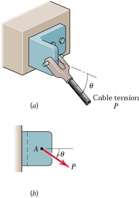
 parallel and perpendicular to the arm AB, and (b) parallel and perpendicular to the arm BC.")
5 2. In the design of the robot to insert the small cylindrical part into a close-fitting circular hole, the robot arm must exert a 90 N force P on the part parallel to the axis of the hole as shown. Determine the components of the force which the part exerts on the robot along axes (a) parallel and perpendicular to the arm AB, and (b) parallel and perpendicular to the arm BC. (2/28)
 parallel and perpendicular to")
6 Determine the components of P along axes (a) parallel and perpendicular to the arm AB, and (b) parallel and perpendicular to the arm BC.

7 3. The unstretched length of the spring is r. When pin P is in an arbitrary position q, determine the x- and y- components of the force which the spring exerts on the pin. F spring =kd Evaluate your answer for r = 400 mm, k = 1.4 kn/m and q = 40. Also when pin P is in the position q = 20, determine the n- and t-components of the force which the spring of modulus k = 1.4 kn/m exerts on the pin. Take r = 400 mm. (2/29)
8 2r O A q F spring r F F spring x spring y P F F l 0 =r. For q, determine x- and y-components of the force spring exerts on the pin. Find force for r = 400 mm, k = 1.4 kn/m and q = 40. For q = 20, determine the n- and t- components of the F. spring spring Sine theorem 2r AP sin sin q sin 2rsin q AP cos sin F spring F springx F springy sin 1 2rsin q AP 1 sin sin 90q 1 q 2rsin q 1 90 sin q 90sin 2rsin q AP AP
9 F F spring spring x y F F spring spring Cosine theorem 2 cosq 90sin sin q 90sin l 0 =r. For q, determine x- and y-components of the force spring exerts on the pin. Find force for r = 400 mm, k = 1.4 kn/m and q = 40. For q = 20, determine the n- and t- components of the F rsin q AP 2rsin q AP AP r (2r) 2( r)(2r)cosq 5r 4r cosq APr 54cosq For the givenvalues AP0.4 54cos m 1 2(0.4)sin sin Fspring kd k( l l0) 1400( ) 219 N Fspring 219cos N x F 219sin N spring y F spring 2r F springx 2r q O A F springy F spring r P

10 4. The circular cam has an offset e = 50 mm and a radius r = 100 mm. For the position where q = 30, the smooth undersurface of the plunger exerts a downward force of 1600 N on the cam normal to the contacting surfaces. In designing the cam bearing it is necessary to calculate the rectangular component F' of this force along the line joining the contact point and the center of the shaft which turns the cam. Find F'.

11 e = 50 mm, r = 100 mm. For q = 30, smooth plunger exerts a downward force of 1600 N on the cam normal to the contacting surfaces. Calculate the rectangular component F' of this force along the line joining the contact point and the center of the shaft which turns the cam.


12 5. The rigid pole and cross arm assembly is supported by the three cables shown. A turnbuckle at D is tightened until it produces a tension T in CD of 1.2 kn. Express T as a vector in terms of its unit vectors i, j and k. Determine the direction angles q x, q y and q z which T makes with the positive x-, y-, and z-axes. Does it make any difference in the result which coordinate system is used? (2/107)
13 T Tn C( 1.5, 0, 4.5) n n CD CD CD r r D/ C D/ C 0.267i j 0.802k T i j 0.802k m T 0.321i j 0.962k T T =1.2 kn. =? Determine the direction angles q x, q y and q z which T makes with the positive x-, y-, and z-axes. Does it make any difference in the result which coordinate system is used? D(0, 3, 0) 1.5i 3 j 4.5k m kn i k r D / C n CD j
14 T T T x x i T T cosq y T T z cosq z T j T T cosq y y x z It does not matter which coordinate system is used. x-y-z or x'-y'-z' systems can be used. Both systems have the same unit vectors. T T =1.2 kn. =? Determine the direction angles q x, q y and q z which T makes with the positive x-, y-, and z-axes. Does it make any difference in the result which coordinate system is used? k T cosq xi cosq y j cosq zk,,, n Tx cosq x T q x y q z CD q i j 0.802k qx q y q z
15 6. Three forces are acting on the eye bolt. If the resultant force shown, determine the magnitude and direction angles of F 3. F R has a magnitude and direction as

16 Given F R determine the magnitude and direction angles of F 3.

17 z A 7. At a certain instant, the locations 5 km of a plane at A and a train at B are monitored by a radar O antenna at O. Determine the distance d between A and B for this instant. x 25 2 km 40 B y
18 A( 5cos 60 cos35, 5cos 60sin 35,5sin 60) A( 2.05, 1.43, 4.33) km B (2cos 25sin 40, 2cos 25cos40, 2sin 25) B (1.17,1.39, 0.85) km r r A/ B A/ B d i j 4.33( 0.85) 3.22i 2.82 j 5.18k r A/ B Determine the distance d between A and B 6.72 km O k z A 5 km x km B r A / B y
19 8. Two cables exert forces on the pipe. Determine the magnitude of the projected component of along the line of action of F F 1. Also determine the angle q between the two cables. 2 q
20 Determine the magnitude of the projected component of F 1 along the line of action of F 2 and the angle q between the two cables. q

21 9. The access door is held in the 30 open position by the chain AB. If the tension in the chain is 100 N, determine the projection of the tension force onto the diagonal axis CD of the door. (2/116)
 ( 52)(0.52) (30)(0.3) 46 N T T n i j k CD CD DC 46 0.8 0.52 0.3 T 36.8i 23.92 j 13.8k N CD T AB =100 N, determine the projection of T AB onto the diagonal axis CD of the door 80i 52 j 30k 0.8i 0.")
22 A(1.2, 0.9 cos30, 0.9sin 30) A(1.2, 0.78, 0.45) m B (0, 0,0.9) m TAB TABnAB 100nAB 1.2i 0.78 j 0.45k nab 0.8i 0.52 j 0.3k 1.50 TAB 80i 52 j 30k N rd / C 1.2i 0.78 j 0.45k ndc rd C 1.50 x / ndc 0.8i 0.52 j 0.3k TCD TABnDC TCD ( 80)( 0.8) ( 52)(0.52) (30)(0.3) 46 N T T n i j k CD CD DC T 36.8i j 13.8k N CD T AB =100 N, determine the projection of T AB onto the diagonal axis CD of the door 80i 52 j 30k 0.8i 0.52 j 0.3k T A / B z r D / C y

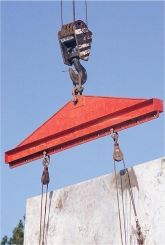
23 10. An overhead crane is used to reposition the boxcar within a railroad car-repair shop. If the boxcar begins to move along the rails when the x-component of the cable tension reaches 3 kn, calculate the necessary tension T in the cable. Determine the angle q xy between the cable and the vertical x-y plane. (2/115)

24 boxcar begins to move when the x-component of the cable tension reaches 3 kn, calculate tension T in the cable. Determine the angle q xy between the cable and the vertical x-y plane.
25 11. The spring of constant k = 2.6 kn/m is attached to the disk at point A and to the end fitting at point B as shown. The spring is unstretched when q A and q B are both zero. If the disk is rotated 15 clockwise and the end fitting is rotated 30 counterclockwise, determine a vector expression for the force which the spring exerts at point A.
26 k = 2.6 kn/m, spring is unstretched when q A and q B are both zero. Determine a vector expression for the force the spring exerts at point A.
Problems (Force Systems)
") 1. Problems (orce Sstems) Problems (orce Sstems). Determine the - components of the tension T which is applied to point A of the bar OA. Neglect the effects of the small pulle at B. Assume that r and are
1. Problems (orce Sstems) Problems (orce Sstems). Determine the - components of the tension T which is applied to point A of the bar OA. Neglect the effects of the small pulle at B. Assume that r and are
(counterclockwise - ccw)
") Problems (on oment) 1. The rod on the power control mechanism for a business jet is subjected to a force of 80 N. Determine the moment of this force about the bearing at. + 0.15sin 6080sin 00.15cos60 80
Problems (on oment) 1. The rod on the power control mechanism for a business jet is subjected to a force of 80 N. Determine the moment of this force about the bearing at. + 0.15sin 6080sin 00.15cos60 80
F = 140 N. 1. A mechanic pulls on the 13-mm combination wrench with the 140 N force shown. Determine the moment of this force about the bolt center O.
 95sin15 1. mechanic pulls on the 1-mm combination wrench with the 140 N force shown. Determine the moment of this force about the bolt center. //y = 140 N y = 140cos5 N 15 o 5 o + o 15 o 95cos15 //x x
1. An experimental device imparts a force of magnitude F = 225 N to the front edge of the rim at A to simulate the effect of a slam dunk.
 1. An experimental device imparts a force of magnitude F = 225 N to the front edge of the rim at A to simulate the effect of a slam dunk. Determine the moments of the force F about point and about point
3D Force Couple System and Resultant. Q.No.1: Replace the force system by an equivalent force and couple moment at point A.
 3D Force Couple System and Resultant Q.No.1: Replace the force system by an equivalent force and couple moment at point A. Q.No.2: Handle forces F1 and F2 are applied to the electric drill. Replace this
Problem " Â F y = 0. ) R A + 2R B + R C = 200 kn ) 2R A + 2R B = 200 kn [using symmetry R A = R C ] ) R A + R B = 100 kn
![Problem  F y = 0. ) R A + 2R B + R C = 200 kn ) 2R A + 2R B = 200 kn [using symmetry R A = R C ] ) R A + R B = 100 kn](/thumbs/88/116790835.jpg "Problem  F y = 0. ) R A + 2R B + R C = 200 kn ) 2R A + 2R B = 200 kn [using symmetry R A = R C ] ) R A + R B = 100 kn") Problem 0. Three cables are attached as shown. Determine the reactions in the supports. Assume R B as redundant. Also, L AD L CD cos 60 m m. uation of uilibrium: + "  F y 0 ) R A cos 60 + R B + R C cos
Problem 0. Three cables are attached as shown. Determine the reactions in the supports. Assume R B as redundant. Also, L AD L CD cos 60 m m. uation of uilibrium: + " Â F y 0 ) R A cos 60 + R B + R C cos
DYNAMICS ME HOMEWORK PROBLEM SETS
 DYNAMICS ME 34010 HOMEWORK PROBLEM SETS Mahmoud M. Safadi 1, M.B. Rubin 2 1 safadi@technion.ac.il, 2 mbrubin@technion.ac.il Faculty of Mechanical Engineering Technion Israel Institute of Technology Spring
Force Couple Systems = Reduction of a Force to an Equivalent Force and Moment (Moving a Force to Another Point) acting on a body has two effects:
 acting on a body has two effects:") ESULTANTS orce Couple Systems = eduction of a orce to an Equivalent orce and Moment (Moving a orce to Another Point) The force acting on a body has two effects: the first one is the tendency to push or
ESULTANTS orce Couple Systems = eduction of a orce to an Equivalent orce and Moment (Moving a orce to Another Point) The force acting on a body has two effects: the first one is the tendency to push or
Equilibrium of a Rigid Body. Engineering Mechanics: Statics
 Equilibrium of a Rigid Body Engineering Mechanics: Statics Chapter Objectives Revising equations of equilibrium of a rigid body in 2D and 3D for the general case. To introduce the concept of the free-body
When a rigid body is in equilibrium, both the resultant force and the resultant couple must be zero.
 When a rigid body is in equilibrium, both the resultant force and the resultant couple must be zero. 0 0 0 0 k M j M i M M k R j R i R F R z y x z y x Forces and moments acting on a rigid body could be
Chap. 3 Rigid Bodies: Equivalent Systems of Forces. External/Internal Forces; Equivalent Forces
 Chap. 3 Rigid Bodies: Equivalent Systems of Forces Treatment of a body as a single particle is not always possible. In general, the size of the body and the specific points of application of the forces
ENGR-1100 Introduction to Engineering Analysis. Lecture 13
 ENGR-1100 Introduction to Engineering Analysis Lecture 13 EQUILIBRIUM OF A RIGID BODY & FREE-BODY DIAGRAMS Today s Objectives: Students will be able to: a) Identify support reactions, and, b) Draw a free-body
Stress Analysis Lecture 3 ME 276 Spring Dr./ Ahmed Mohamed Nagib Elmekawy
 Stress Analysis Lecture 3 ME 276 Spring 2017-2018 Dr./ Ahmed Mohamed Nagib Elmekawy Axial Stress 2 Beam under the action of two tensile forces 3 Beam under the action of two tensile forces 4 Shear Stress
The University of Melbourne Engineering Mechanics
 The University of Melbourne 436-291 Engineering Mechanics Tutorial Eleven Instantaneous Centre and General Motion Part A (Introductory) 1. (Problem 5/93 from Meriam and Kraige - Dynamics) For the instant
(48) CHAPTER 3: TORSION
 CHAPTER 3: TORSION") (48) CHAPTER 3: TORSION Introduction: In this chapter structural members and machine parts that are in torsion will be considered. More specifically, you will analyze the stresses and strains in members
(48) CHAPTER 3: TORSION Introduction: In this chapter structural members and machine parts that are in torsion will be considered. More specifically, you will analyze the stresses and strains in members
acting on a body has two effects:
 The force acting on a body has two effects: the first one is the tendency to push or pull the body in the direction of the force, and the second one is to rotate the body about any fixed axis which does
VALLIAMMAI ENGINEERING COLLEGE SRM NAGAR, KATTANKULATHUR DEPARTMENT OF MECHANICAL ENGINEERING
 VALLIAMMAI ENGINEERING COLLEGE SRM NAGAR, KATTANKULATHUR 603203 DEPARTMENT OF MECHANICAL ENGINEERING BRANCH: MECHANICAL YEAR / SEMESTER: I / II UNIT 1 PART- A 1. State Newton's three laws of motion? 2.
SOLUTION 8 1. a+ M B = 0; N A = 0. N A = kn = 16.5 kn. Ans. + c F y = 0; N B = 0
 8 1. The mine car and its contents have a total mass of 6 Mg and a center of gravity at G. If the coefficient of static friction between the wheels and the tracks is m s = 0.4 when the wheels are locked,
EQUATIONS OF EQUILIBRIUM & TWO- AND THREE-FORCE MEMEBERS
 EQUATIONS OF EQUILIBRIUM & TWO- AND THREE-FORCE MEMEBERS Today s Objectives: Students will be able to: a) Apply equations of equilibrium to solve for unknowns, and b) Recognize two-force members. In-Class
STATICS. Bodies. Vector Mechanics for Engineers: Statics VECTOR MECHANICS FOR ENGINEERS: Design of a support
 4 Equilibrium CHAPTER VECTOR MECHANICS FOR ENGINEERS: STATICS Ferdinand P. Beer E. Russell Johnston, Jr. Lecture Notes: J. Walt Oler Texas Tech University of Rigid Bodies 2010 The McGraw-Hill Companies,
The case where there is no net effect of the forces acting on a rigid body
 The case where there is no net effect of the forces acting on a rigid body Outline: Introduction and Definition of Equilibrium Equilibrium in Two-Dimensions Special cases Equilibrium in Three-Dimensions
When a rigid body is in equilibrium, both the resultant force and the resultant couple must be zero.
 When a rigid body is in equilibrium, both the resultant force and the resultant couple must be zero. 0 0 0 0 k M j M i M M k R j R i R F R z y x z y x Forces and moments acting on a rigid body could be
Mechanics: Scalars and Vectors
 Mechanics: Scalars and Vectors Scalar Onl magnitude is associated with it Vector e.g., time, volume, densit, speed, energ, mass etc. Possess direction as well as magnitude Parallelogram law of addition
Chapter 2 Statics of Particles. Resultant of Two Forces 8/28/2014. The effects of forces on particles:
 Chapter 2 Statics of Particles The effects of forces on particles: - replacing multiple forces acting on a particle with a single equivalent or resultant force, - relations between forces acting on a particle
Statics Chapter II Fall 2018 Exercises Corresponding to Sections 2.1, 2.2, and 2.3
 Statics Chapter II Fall 2018 Exercises Corresponding to Sections 2.1, 2.2, and 2.3 2 3 Determine the magnitude of the resultant force FR = F1 + F2 and its direction, measured counterclockwise from the
EQUILIBRIUM OF A RIGID BODY & FREE-BODY DIAGRAMS
 Today s Objectives: Students will be able to: EQUILIBRIUM OF A RIGID BODY & FREE-BODY DIAGRAMS a) Identify support reactions, and, b) Draw a free-body diagram. In-Class Activities: Check Homework Reading
Announcements. Equilibrium of a Particle in 2-D
 nnouncements Equilibrium of a Particle in 2-D Today s Objectives Draw a free body diagram (FBD) pply equations of equilibrium to solve a 2-D problem Class ctivities pplications What, why, and how of a
PROBLEMS. m s TAC. m = 60 kg/m, determine the tension in the two supporting cables and the reaction at D.
 1. he uniform I-beam has a mass of 60 kg per meter of its length. Determine the tension in the two supporting cables and the reaction at D. (3/62) A( 500) m (5 23) m m = 60 kg/m determine the tension in
TUTORIAL SHEET 1. magnitude of P and the values of ø and θ. Ans: ø =74 0 and θ= 53 0
 TUTORIAL SHEET 1 1. The rectangular platform is hinged at A and B and supported by a cable which passes over a frictionless hook at E. Knowing that the tension in the cable is 1349N, determine the moment
Name: Fall 2014 CLOSED BOOK
 Name: Fall 2014 1. Rod AB with weight W = 40 lb is pinned at A to a vertical axle which rotates with constant angular velocity ω =15 rad/s. The rod position is maintained by a horizontal wire BC. Determine
Engineering Mechanics: Statics
 Engineering Mechanics: Statics Chapter 2: Force Systems Part A: Two Dimensional Force Systems Force Force = an action of one body on another Vector quantity External and Internal forces Mechanics of Rigid
SOLUTION 4 1. If A, B, and D are given vectors, prove the distributive law for the vector cross product, i.e., A : (B + D) = (A : B) + (A : D).
 = (A : B) + (A : D).") 4 1. If A, B, and D are given vectors, prove the distributive law for the vector cross product, i.e., A : (B + D) = (A : B) + (A : D). Consider the three vectors; with A vertical. Note obd is perpendicular
4 1. If A, B, and D are given vectors, prove the distributive law for the vector cross product, i.e., A : (B + D) = (A : B) + (A : D). Consider the three vectors; with A vertical. Note obd is perpendicular
Final Exam April 30, 2013
 Final Exam Instructions: You have 120 minutes to complete this exam. This is a closed-book, closed-notes exam. You are allowed to use a calculator during the exam. Usage of mobile phones and other electronic
SIMPLE TRUSSES, THE METHOD OF JOINTS, & ZERO-FORCE MEMBERS
 SIMPLE TRUSSES, THE METHOD OF JOINTS, & ZERO-FORCE MEMBERS Today s Objectives: Students will be able to: a) Define a simple truss. b) Determine the forces in members of a simple truss. c) Identify zero-force
Unit 1. (a) tan α = (b) tan α = (c) tan α = (d) tan α =
 tan α = (b) tan α = (c) tan α = (d) tan α =") Unit 1 1. The subjects Engineering Mechanics deals with (a) Static (b) kinematics (c) Kinetics (d) All of the above 2. If the resultant of two forces P and Q is acting at an angle α with P, then (a) tan
Unit 1 1. The subjects Engineering Mechanics deals with (a) Static (b) kinematics (c) Kinetics (d) All of the above 2. If the resultant of two forces P and Q is acting at an angle α with P, then (a) tan
Practice Test 3. Name: Date: ID: A. Multiple Choice Identify the choice that best completes the statement or answers the question.
 Name: Date: _ Practice Test 3 Multiple Choice Identify the choice that best completes the statement or answers the question. 1. A wheel rotates about a fixed axis with an initial angular velocity of 20
Engineering Mechanics I. Phongsaen PITAKWATCHARA
 2103-213 Engineering Mechanics I phongsaen@gmail.com December 6, 2007 Contents Preface iii 1 Introduction to Statics 1 1.0 Outline................................. 2 1.1 Basic Concepts............................
Free Body Diagram: Solution: The maximum load which can be safely supported by EACH of the support members is: ANS: A =0.217 in 2
 Problem 10.9 The angle β of the system in Problem 10.8 is 60. The bars are made of a material that will safely support a tensile normal stress of 8 ksi. Based on this criterion, if you want to design the
King Fahd University of Petroleum and Minerals Department of Physics. Final Exam 041. Answer key - First choice is the correct answer
 King Fahd University of Petroleum and Minerals Department of Physics MSK Final Exam 041 Answer key - First choice is the correct answer Q1 A 20 kg uniform ladder is leaning against a frictionless wall
UNIVERSITY OF SASKATCHEWAN GE MECHANICS III FINAL EXAM APRIL 18, 2011 Professor A. Dolovich A CLOSED BOOK EXAMINATION TIME: 3 HOURS
 UNIVERSITY OF SASKATCHEWAN GE 226.3 MECHANICS III FINAL EXAM APRIL 18, 2011 Professor A. Dolovich A CLOSED BOOK EXAMINATION TIME: 3 HOURS LAST NAME (printed): FIRST NAME (printed): STUDENT NUMBER: EXAMINATION
Torque rotational force which causes a change in rotational motion. This force is defined by linear force multiplied by a radius.
 Warm up A remote-controlled car's wheel accelerates at 22.4 rad/s 2. If the wheel begins with an angular speed of 10.8 rad/s, what is the wheel's angular speed after exactly three full turns? AP Physics
Chapter Objectives. Copyright 2011 Pearson Education South Asia Pte Ltd
 Chapter Objectives To develop the equations of equilibrium for a rigid body. To introduce the concept of the free-body diagram for a rigid body. To show how to solve rigid-body equilibrium problems using
Chapter 9. Rotational Dynamics
 Chapter 9 Rotational Dynamics In pure translational motion, all points on an object travel on parallel paths. The most general motion is a combination of translation and rotation. 1) Torque Produces angular
Samantha Ramirez, MSE. Stress. The intensity of the internal force acting on a specific plane (area) passing through a point. F 2
 passing through a point. F 2") Samantha Ramirez, MSE Stress The intensity of the internal force acting on a specific plane (area) passing through a point. Δ ΔA Δ z Δ 1 2 ΔA Δ x Δ y ΔA is an infinitesimal size area with a uniform force
Samantha Ramirez, MSE Stress The intensity of the internal force acting on a specific plane (area) passing through a point. Δ ΔA Δ z Δ 1 2 ΔA Δ x Δ y ΔA is an infinitesimal size area with a uniform force
Equilibrium. Rigid Bodies VECTOR MECHANICS FOR ENGINEERS: STATICS. Eighth Edition CHAPTER. Ferdinand P. Beer E. Russell Johnston, Jr.
 Eighth E 4 Equilibrium CHAPTER VECTOR MECHANICS FOR ENGINEERS: STATICS Ferdinand P. Beer E. Russell Johnston, Jr. Lecture Notes: J. Walt Oler Texas Tech University of Rigid Bodies Contents Introduction
KINGS COLLEGE OF ENGINEERING ENGINEERING MECHANICS QUESTION BANK UNIT I - PART-A
 KINGS COLLEGE OF ENGINEERING ENGINEERING MECHANICS QUESTION BANK Sub. Code: CE1151 Sub. Name: Engg. Mechanics UNIT I - PART-A Sem / Year II / I 1.Distinguish the following system of forces with a suitable
6. Find the net torque on the wheel in Figure about the axle through O if a = 10.0 cm and b = 25.0 cm.
 1. During a certain period of time, the angular position of a swinging door is described by θ = 5.00 + 10.0t + 2.00t 2, where θ is in radians and t is in seconds. Determine the angular position, angular
SRSD 2093: Engineering Mechanics 2SRRI SECTION 19 ROOM 7, LEVEL 14, MENARA RAZAK
 SRSD 2093: Engineering Mechanics 2SRRI SECTION 19 ROOM 7, LEVEL 14, MENARA RAZAK SIMPLE TRUSSES, THE METHOD OF JOINTS, & ZERO-FORCE MEMBERS Today s Objectives: Students will be able to: a) Define a simple
STATICS. Rigid Bodies: Equivalent Systems of Forces VECTOR MECHANICS FOR ENGINEERS: Eighth Edition CHAPTER. Ferdinand P. Beer E. Russell Johnston, Jr.
 Eighth E CHAPTER VECTOR MECHANICS FOR ENGINEERS: STATICS Ferdinand P. Beer E. Russell Johnston, Jr. Lecture Notes: J. Walt Oler Texas Tech University Rigid Bodies: Equivalent Systems of Forces Contents
ME 230 Kinematics and Dynamics
 ME 230 Kinematics and Dynamics Wei-Chih Wang Department of Mechanical Engineering University of Washington Lecture 6: Particle Kinetics Kinetics of a particle (Chapter 13) - 13.4-13.6 Chapter 13: Objectives
Force and Moment. Figure 1 Figure 2
 Force and Moment 1 Determine the magnitude and direction of the resultant of the two forces shown, using (a) the parallelogram law (b) the sine law. [1391 N, 47.8 ] Figure 1 Figure 2 2 The force F of magnitude
SECTION A. 8 kn/m. C 3 m 3m
 SECTION Question 1 150 m 40 kn 5 kn 8 kn/m C 3 m 3m D 50 ll dimensions in mm 15 15 Figure Q1(a) Figure Q1(b) The horizontal beam CD shown in Figure Q1(a) has a uniform cross-section as shown in Figure
PLANAR RIGID BODY MOTION: TRANSLATION &
 PLANAR RIGID BODY MOTION: TRANSLATION & Today s Objectives : ROTATION Students will be able to: 1. Analyze the kinematics of a rigid body undergoing planar translation or rotation about a fixed axis. In-Class
BTECH MECHANICAL PRINCIPLES AND APPLICATIONS. Level 3 Unit 5
 BTECH MECHANICAL PRINCIPLES AND APPLICATIONS Level 3 Unit 5 FORCES AS VECTORS Vectors have a magnitude (amount) and a direction. Forces are vectors FORCES AS VECTORS (2 FORCES) Forces F1 and F2 are in
Final Exam December 15, 2014
 Final Exam Instructions: You have 120 minutes to complete this exam. This is a closed-book, closed-notes exam. You are allowed to use the ME approved calculator only during the exam. Usage of mobile phones
RELATIVE MOTION ANALYSIS: VELOCITY (Section 16.5)
") RELATIVE MOTION ANALYSIS: VELOCITY (Section 16.5) Today s Objectives: Students will be able to: a) Describe the velocity of a rigid body in terms of translation and rotation components. b) Perform a relative-motion
RELATIVE MOTION ANALYSIS: VELOCITY (Section 16.5) Today s Objectives: Students will be able to: a) Describe the velocity of a rigid body in terms of translation and rotation components. b) Perform a relative-motion
Determine the resultant internal loadings acting on the cross section at C of the beam shown in Fig. 1 4a.
 E X M P L E 1.1 Determine the resultant internal loadings acting on the cross section at of the beam shown in Fig. 1 a. 70 N/m m 6 m Fig. 1 Support Reactions. This problem can be solved in the most direct
CHAPTER 2: EQUILIBRIUM OF RIGID BODIES
 For a rigid body to be in equilibrium, the net force as well as the net moment about any arbitrary point O must be zero Summation of all external forces. Equilibrium: Sum of moments of all external forces.
Chapter 12 Static Equilibrium
 Chapter Static Equilibrium. Analysis Model: Rigid Body in Equilibrium. More on the Center of Gravity. Examples of Rigid Objects in Static Equilibrium CHAPTER : STATIC EQUILIBRIUM AND ELASTICITY.) The Conditions
Exam 3 April 16, 2014
 Exam 3 Instructions: You have 60 minutes to complete this exam. This is a closed-book, closed-notes exam. You are allowed to use a calculator during the exam. Usage of mobile phones and other electronic
Addis Ababa University Addis Ababa Institute of Technology School Of Mechanical and Industrial Engineering Extension Division Assignment 2
 Addis Ababa University Addis Ababa Institute of Technology School Of Mechanical and Industrial Engineering Extension Division Assignment 2 1. The 50-kg crate is projected along the floor with an initial
EQUATIONS OF EQUILIBRIUM & TWO- AND THREE-FORCE MEMEBERS
 EQUATIONS OF EQUILIBRIUM & TWO- AND THREE-FORCE MEMEBERS Today s Objectives: Students will be able to: a) Apply equations of equilibrium to solve for unknowns, and, b) Recognize two-force members. In-Class
Equilibrium of a Particle
 ME 108 - Statics Equilibrium of a Particle Chapter 3 Applications For a spool of given weight, what are the forces in cables AB and AC? Applications For a given weight of the lights, what are the forces
[5] Stress and Strain
![[5] Stress and Strain](/thumbs/95/123344550.jpg "[5] Stress and Strain") [5] Stress and Strain Page 1 of 34 [5] Stress and Strain [5.1] Internal Stress of Solids [5.2] Design of Simple Connections (will not be covered in class) [5.3] Deformation and Strain [5.4] Hooke s Law
[5] Stress and Strain Page 1 of 34 [5] Stress and Strain [5.1] Internal Stress of Solids [5.2] Design of Simple Connections (will not be covered in class) [5.3] Deformation and Strain [5.4] Hooke s Law
Stress Transformation Equations: u = +135 (Fig. a) s x = 80 MPa s y = 0 t xy = 45 MPa. we obtain, cos u + t xy sin 2u. s x = s x + s y.
 s x = 80 MPa s y = 0 t xy = 45 MPa. we obtain, cos u + t xy sin 2u. s x = s x + s y.") 014 Pearson Education, Inc., Upper Saddle River, NJ. All rights reserved. This material is protected under all copyright laws as they currently 9 7. Determine the normal stress and shear stress acting
014 Pearson Education, Inc., Upper Saddle River, NJ. All rights reserved. This material is protected under all copyright laws as they currently 9 7. Determine the normal stress and shear stress acting
P-2: The screw eye is subjected to two forces, ԦF 1 and ԦF 2. Determine the magnitude and direction of the resultant force.
 P-1: ԦA=Ԧi +Ԧj -5k and B =Ԧi - 7Ԧj -6k. Detemine;?????? - A B B A A B B A B A B A 7 P-: The scew ee is subjected to two foces, Ԧ 1 and Ԧ. Detemine the magnitude and diection of the esultant foce. P-: The
SOLUTION 8 7. To hold lever: a+ M O = 0; F B (0.15) - 5 = 0; F B = N. Require = N N B = N 0.3. Lever,
 - 5 = 0; F B = N. Require = N N B = N 0.3. Lever,") 8 3. If the coefficient of static friction at is m s = 0.4 and the collar at is smooth so it only exerts a horizontal force on the pipe, determine the minimum distance x so that the bracket can support
8 3. If the coefficient of static friction at is m s = 0.4 and the collar at is smooth so it only exerts a horizontal force on the pipe, determine the minimum distance x so that the bracket can support
Problems (Equilibrium of Particles)
") 1. he 4kg block rests on the rough surface. Length of the spring is 18 mm in the position shown. Unstretched length of the spring is 2 mm. Determine the coefficient of friction required for the equilibrium.
1. he 4kg block rests on the rough surface. Length of the spring is 18 mm in the position shown. Unstretched length of the spring is 2 mm. Determine the coefficient of friction required for the equilibrium.
Dynamics Plane kinematics of rigid bodies Section 4: TJW Rotation: Example 1
 Section 4: TJW Rotation: Example 1 The pinion A of the hoist motor drives gear B, which is attached to the hoisting drum. The load L is lifted from its rest position and acquires an upward velocity of
GCE214 Applied Mechanics-Statics. Lecture 04: 27/09/2017
 GCE214 Applied Mechanics-Statics Lecture 04: 27/09/2017 Dr. Ayokunle O. Balogun balogun.ayokunle@lmu.edu.ng Class: Wednesday (3 5 pm) Venue: LT1 Etiquettes and MOP Attendance is a requirement. There may
.VALLIAMMAI ENGINEERING COLLEGE
 .VALLIAMMAI ENGINEERING COLLEGE SRM Nagar, Kattankulathur 603 203 DEPARTMENT OF GENERAL ENGINEERING QUESTION BANK II SEMESTER GE 8292- Engineering Mechanics Regulation 2017 Academic Year 2017 18 VALLIAMMAI
Statics deal with the condition of equilibrium of bodies acted upon by forces.
 Mechanics It is defined as that branch of science, which describes and predicts the conditions of rest or motion of bodies under the action of forces. Engineering mechanics applies the principle of mechanics
Phys101 Third Major-161 Zero Version Coordinator: Dr. Ayman S. El-Said Monday, December 19, 2016 Page: 1
 Coordinator: Dr. Ayman S. El-Said Monday, December 19, 2016 Page: 1 Q1. A water molecule (H 2 O) consists of an oxygen (O) atom of mass 16m and two hydrogen (H) atoms, each of mass m, bound to it (see
STRESS. Bar. ! Stress. ! Average Normal Stress in an Axially Loaded. ! Average Shear Stress. ! Allowable Stress. ! Design of Simple Connections
 STRESS! Stress Evisdom! verage Normal Stress in an xially Loaded ar! verage Shear Stress! llowable Stress! Design of Simple onnections 1 Equilibrium of a Deformable ody ody Force w F R x w(s). D s y Support
Name. MECH 223 Engineering Statics. Midterm 1, February 24 th 2015
 1 Name MECH 223 Engineering Statics Midterm 1, February 24 th 2015 Question 1 (20 + 5 points) (a) (5 points) Form the vector products B C and B C (where B = B ) and use the result to prove the identity
APPLIED MECHANICS I Resultant of Concurrent Forces Consider a body acted upon by co-planar forces as shown in Fig 1.1(a).
.") PPLIED MECHNICS I 1. Introduction to Mechanics Mechanics is a science that describes and predicts the conditions of rest or motion of bodies under the action of forces. It is divided into three parts 1.
PPLIED MECHNICS I 1. Introduction to Mechanics Mechanics is a science that describes and predicts the conditions of rest or motion of bodies under the action of forces. It is divided into three parts 1.
Magnetic Force Acting on a Current- Carrying Conductor IL B
 Magnetic Force Acting on a Current- Carrying Conductor A segment of a current-carrying wire in a magnetic field. The magnetic force exerted on each charge making up the current is qvd and the net force
EMA 3702 Mechanics & Materials Science (Mechanics of Materials) Chapter 3 Torsion
 Chapter 3 Torsion") EMA 3702 Mechanics & Materials Science (Mechanics of Materials) Chapter 3 Torsion Introduction Stress and strain in components subjected to torque T Circular Cross-section shape Material Shaft design Non-circular
EMA 3702 Mechanics & Materials Science (Mechanics of Materials) Chapter 3 Torsion Introduction Stress and strain in components subjected to torque T Circular Cross-section shape Material Shaft design Non-circular
 第 1 頁, 共 7 頁 Chap10 1. Test Bank, Question 3 One revolution per minute is about: 0.0524 rad/s 0.105 rad/s 0.95 rad/s 1.57 rad/s 6.28 rad/s 2. *Chapter 10, Problem 8 The angular acceleration of a wheel
Tuesday, February 11, Chapter 3. Load and Stress Analysis. Dr. Mohammad Suliman Abuhaiba, PE
 1 Chapter 3 Load and Stress Analysis 2 Chapter Outline Equilibrium & Free-Body Diagrams Shear Force and Bending Moments in Beams Singularity Functions Stress Cartesian Stress Components Mohr s Circle for
20 Torque & Circular Motion
 Chapter 0 Torque & Circular Motion 0 Torque & Circular Motion The mistake that crops up in the application of Newton s nd Law for Rotational Motion involves the replacement of the sum of the torques about
Chapter 9. Rotational Dynamics
 Chapter 9 Rotational Dynamics In pure translational motion, all points on an object travel on parallel paths. The most general motion is a combination of translation and rotation. 1) Torque Produces angular
Chapter -4- Force System Resultant
 Ishik University / Sulaimani Civil Engineering Department Chapter -4- Force System Resultant 1 2 1 CHAPTER OBJECTIVES To discuss the concept of the moment of a force and show how to calculate it in two
Ishik University / Sulaimani Architecture Department. Structure. ARCH 214 Chapter -5- Equilibrium of a Rigid Body
 Ishik University / Sulaimani Architecture Department 1 Structure ARCH 214 Chapter -5- Equilibrium of a Rigid Body CHAPTER OBJECTIVES To develop the equations of equilibrium for a rigid body. To introduce
IDE 110 Mechanics of Materials Spring 2006 Final Examination FOR GRADING ONLY
 Spring 2006 Final Examination STUDENT S NAME (please print) STUDENT S SIGNATURE STUDENT NUMBER IDE 110 CLASS SECTION INSTRUCTOR S NAME Do not turn this page until instructed to start. Write your name on
1 MR SAMPLE EXAM 3 FALL 2013
 SAMPLE EXAM 3 FALL 013 1. A merry-go-round rotates from rest with an angular acceleration of 1.56 rad/s. How long does it take to rotate through the first rev? A) s B) 4 s C) 6 s D) 8 s E) 10 s. A wheel,
5. Plane Kinetics of Rigid Bodies
 5. Plane Kinetics of Rigid Bodies 5.1 Mass moments of inertia 5.2 General equations of motion 5.3 Translation 5.4 Fixed axis rotation 5.5 General plane motion 5.6 Work and energy relations 5.7 Impulse
h p://edugen.wileyplus.com/edugen/courses/crs1404/pc/c05/c2hlch... CHAPTER 5 MOMENTS 1 of 3 10-Sep-12 16:35
 Peter Christopher/Masterfile... 1 of 3 10-Sep-12 16:35 CHAPTER 5 MOMENTS Peter Christopher/Masterfile... 2 of 3 10-Sep-12 16:35 Peter Christopher/Masterfile In Chapter 4 we considered the forces that push
PROBLEMS ON EQUILIBRIUM OF PARTICLES
 O EQUILIBRIUM O PRICLES 1. ind the angle of tilt q with the horiontal so that the contact force at B will be one-half that at for the smooth clinder. (3/15) q?, contact force at B will be one-half that
'- '- p = 800(i cos j sin 270 ) = Oi - -'-,--,--J~36. T = ITI(icos 22 + j sin 22 ) = ITI(0.927i
 = Oi - -'-,--,--J~36. T = ITI(icos 22 + j sin 22 ) = ITI(0.927i") Problem 3.6 A zoologist estimates that the jaw of a predator, Martes, is subjected to a force P as large as 800 N. What forces T and M must be exerted by the temporalis and masseter muscles to support
Problem 3.6 A zoologist estimates that the jaw of a predator, Martes, is subjected to a force P as large as 800 N. What forces T and M must be exerted by the temporalis and masseter muscles to support
Moving Reference Frame Kinematics Homework
 Chapter 3 Moving Reference Frame Kinematics Homework Freeform c 2016 3-1 3-2 Freeform c 2016 Homework 3. Given: n L-shaped telescoping arm is pinned to ground at point. The arm is rotating counterclockwise
Chapter 8. Rotational Equilibrium and Rotational Dynamics. 1. Torque. 2. Torque and Equilibrium. 3. Center of Mass and Center of Gravity
 Chapter 8 Rotational Equilibrium and Rotational Dynamics 1. Torque 2. Torque and Equilibrium 3. Center of Mass and Center of Gravity 4. Torque and angular acceleration 5. Rotational Kinetic energy 6. Angular
Ch. 3: Equilibrium. 3.0 Outline Mechanical System Isolation (FBD) 2-D Systems Equilibrium Conditions 3-D Systems Equilibrium Conditions. 3.
 2-D Systems Equilibrium Conditions 3-D Systems Equilibrium Conditions. 3.") 3.0 Outline Mechanical System Isolation (FBD) 2-D Systems Equilibrium Conditions 3-D Systems Equilibrium Conditions 3.0 Outline 3.0 Outline When a body is in equilibrium, the resultant on the body is zero.
3.0 Outline Mechanical System Isolation (FBD) 2-D Systems Equilibrium Conditions 3-D Systems Equilibrium Conditions 3.0 Outline 3.0 Outline When a body is in equilibrium, the resultant on the body is zero.
Equilibrium & Elasticity
 PHYS 101 Previous Exam Problems CHAPTER 12 Equilibrium & Elasticity Static equilibrium Elasticity 1. A uniform steel bar of length 3.0 m and weight 20 N rests on two supports (A and B) at its ends. A block
Eng Sample Test 4
 1. An adjustable tow bar connecting the tractor unit H with the landing gear J of a large aircraft is shown in the figure. Adjusting the height of the hook F at the end of the tow bar is accomplished by
PHY 1150 Doug Davis Chapter 8; Static Equilibrium 8.3, 10, 22, 29, 52, 55, 56, 74
 PHY 1150 Doug Davis Chapter 8; Static Equilibrium 8.3, 10, 22, 29, 52, 55, 56, 74 8.3 A 2-kg ball is held in position by a horizontal string and a string that makes an angle of 30 with the vertical, as
4.0 m s 2. 2 A submarine descends vertically at constant velocity. The three forces acting on the submarine are viscous drag, upthrust and weight.
 1 1 wooden block of mass 0.60 kg is on a rough horizontal surface. force of 12 N is applied to the block and it accelerates at 4.0 m s 2. wooden block 4.0 m s 2 12 N hat is the magnitude of the frictional
STATICS. Bodies VECTOR MECHANICS FOR ENGINEERS: Ninth Edition CHAPTER. Ferdinand P. Beer E. Russell Johnston, Jr.
 N E 4 Equilibrium CHAPTER VECTOR MECHANICS FOR ENGINEERS: STATICS Ferdinand P. Beer E. Russell Johnston, Jr. Lecture Notes: J. Walt Oler Texas Tech University of Rigid Bodies 2010 The McGraw-Hill Companies,
MEE224: Engineering Mechanics Lecture 4
 Lecture 4: Structural Analysis Part 1: Trusses So far we have only analysed forces and moments on a single rigid body, i.e. bars. Remember that a structure is a formed by and this lecture will investigate
Addis Ababa University Addis Ababa Institute of Technology School Of Mechanical and Industrial Engineering Extension Division` Assignment 1
 Assignment 1 1. Vehicle B is stopped at a traffic light, as shown in the figure. At the instant that the light turns green, vehicle B starts to accelerate at 0.9144m/s 2. At this time vehicle A is 91.44m