Ch. 3: Equilibrium. 3.0 Outline Mechanical System Isolation (FBD) 2-D Systems Equilibrium Conditions 3-D Systems Equilibrium Conditions. 3.
|
|
|
- Dustin Cannon
- 5 years ago
- Views:
Transcription
1 3.0 Outline Mechanical System Isolation (FBD) 2-D Systems Equilibrium Conditions 3-D Systems Equilibrium Conditions 3.0 Outline
2 3.0 Outline When a body is in equilibrium, the resultant on the body is zero. And if the resultant on a body is zero, the body is in equilibrium. So, F = 0 M = 0 is the necessary and sufficient conditions for equilibrium. 3.0 Outline
3 3.1 Mechanical System Isolation (FBD) Free-Body Diagram (FBD) is the most important first step in the mechanics problems. It defines clearly the interested system to be analyzed. It represents all forces which act on the system. The system may be rigid, nonrigid, or their combinations. The system may be in fluid, gaseous, solid, or their combinations. FBD represents the isolated / combination of bodies as a single body. Corresponding indicated forces may be 1. Contact force with other bodies that are removed virtually. 2. Body force such as gravitational or magnetic attraction forces. 3.1 FBD

4 3.1 FBD
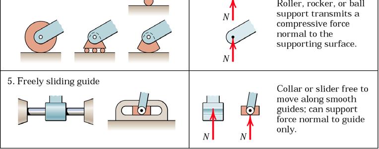
5 Remarks 1. Force by flexible cable is always a tension. Weight of the cable may be significant. 2. Smooth surface ideally cannot support the tangential or frictional force. Contact force of the rough surface may not necessarily be normal to the tangential surface. 3. Roller, rocker, smooth guide, or slider ideally eliminate the frictional force. That is the supports cannot provide the resistance to motion in the tangential direction. 4. Pin connection provides support force in any direction normal to the pin axis. If the joint is not free to turn, a resisting couple may also be supported. 3.1 FBD
6 3.1 FBD
7 Remarks 5. The built-in / fixed support of the beam is capable of supporting the axial force, the shear force, and the bending moment. 6. Gravitational force is a kind of distributed non-contact force. The resultant single force is the weight acted through C.M. towards the center of the earth. 7. Remote action force has the same overall effects on a rigid body as direct contact force of equal magnitude and direction. 8. On the FBD, the force exerted on the body to be isolated by the body to be removed is indicated. 9. Sense of the force exerted on the FBD by the removed bodies opposes the movement which would occur if those bodies were removed. 3.1 FBD
8 Remarks 10. If the correct sense cannot be known at first place, the sense of the scalar component is arbitrarily assigned. Upon computation, a negative algebraic sign indicates that the correct sense is opposite to that assigned. 3.1 FBD
9 Construction of FBD 1. Make decision which body or system is to be isolated. That system will usually involve the unknown quantities. 2. Draw complete external boundary of the system to completely isolate it from all other contacting or attracting bodies. 3. All forces that act on the isolated body by the removed contacting and attracting bodies are represented on the isolated body diagram. Forces should be indicated by vector arrows, each with its magnitude, direction, and sense. Consistency of the unknowns must be carried throughout the calculation. 4. Assign the convenient coordinate axes. Only after the FBD is completed should the governing equations be applied. 3.1 FBD
10 3.1 FBD
11 Note 1. Include as much as possible the system in FBD while the unknowns are still being revealed. 2. Internal forces to a rigid assembly of members do not influence the values of the external reactions. And so the external response of the mechanism as a whole would be unchanged. 3. Include the weights of the members on FBD. 4. Try to get the correct sense of unknown vectors by visualizing the motion of the whole system when the supports are pretended to disappear. The correct sense will oppose the motion s direction. 5. Follow the action of force prototypes in determining the forces acted by the removed bodies. 3.1 FBD
12 3.1 FBD
13 A x Ay M O O x O y B x A x A y 3.1 FBD
14 3.1 FBD
15 F F B y A x M A A x 3.1 FBD


16 3.1 FBD
17 3.1 FBD
18 1. T y x mg F N 2. P mg On verge of being rolled over means the normal force N = 0 R N = 0 y x T 3.1 FBD
19 3. T y R x x R y 4. L N y A X mg m O g x A y 3.1 FBD

20 5. O mg T y x F N MO = 0 6. R y A X B X x A y B y 3.1 FBD


21 7. T Ch. 3: Equilibrium y A X x 8. T A y B X mg y A X B y x A y L 3.1 FBD
22 3.2 2-D Equilibrium Conditions A body is in equilibrium if all forces and moments applied to it are in balance. In scalar form, F = 0 F = 0 M = 0 x y O The x-y coordinate system and the moment point O can be chosen arbitrarily. Complete equilibrium in 2-D motion must satisfy all three equations. However, they are independent to each other. That is, equilibrium may only be satisfied in some generalized coordinates. System in equilibrium may stay still or move with constant velocity. In both cases, the acceleration is zero D Eqilibrium Conditions
23 Categories of equilibrium Ch. 3: Equilibrium Some equations are automatically satisfied and so contribute nothing in solving the problems D Eqilibrium Conditions
24 Weights of the members negligible Equilibrium of a body under the action of two force only: The forces must be equal, opposite, and collinear D Eqilibrium Conditions
25 Equilibrium of a body under the action of three force only: The lines of action of the three forces must be concurrent. The only exception is when the three forces are parallel. The system may be reduced to the three-force member by successive addition of the known forces. If all forces are concurrent, then the equilibrium statement calls for the closure of the polygon of forces D Eqilibrium Conditions
 3.")
26 Alternative Equilibrium Equations Three independent equilibrium conditions: F = 0 M = 0 M = 0 x A B ( AB x-direction) D Eqilibrium Conditions

27 Alternative Equilibrium Equations Three independent equilibrium conditions: M = 0 M = 0 M = 0 A B C A, B, and C are not on the same straight line D Eqilibrium Conditions
28 Constraints and Statical Determinacy The equilibrium equations may not always solve all unknowns in the problem. Simply put, if #unknowns (including geometrical variables) > #equations, then we cannot solve it. This is because the system has more constraints than necessary to maintain the equilibruim. This is call statically indeterminate system. Extra equations, from force-deformation material properties, must also be applied to solve the redundant constraints D Eqilibrium Conditions
29 Constraints and Statical Determinacy P mg Q #unknowns = 2 #equilibrium eqs. = 2 statically determinate A y A x A x Ay B y B x P #unknowns = 4 #equilibrium eqs. = 3 statically indeterminate B y C y B x C x F #unknowns = 6 #equilibrium eqs. = 3 statically indeterminate D Eqilibrium Conditions


30 Adequacy of Constraints Ch. 3: Equilibrium D Eqilibrium Conditions
31 Problem Solution 1. List known unknown quantities, and check the number of unknowns and the number of available independent equations. 2. Determine the isolated system and draw FBD. 3. Assign a convenient set of coordinate systems. Choose suitable moment centers for calculation. 4. Write down the governing equation, e.g. M O = 0, before the calculation. 5. Choose the suitable method in solving the problem: scalar, vector, or geometric approach D Eqilibrium Conditions
32 P. 3/27 In a procedure to evaluate the strength of the triceps muscle, a person pushes down on a load cell with the palm of his hand as indicated in the figure. If the load-cell reading is 160 N, determine the vertical tensile force F generated by the triceps muscle. The mass of the lower arm is 1.5 kg with mass center at G. State any assumptions D Eqilibrium Conditions

33 P. 3/27 Assumption: contraction force from biceps muscle acts at point O 1. Known: weight of lower hand, pushing force Unknown: triceps force, biceps force 2. FBD: lower hand T C y x MO = 0 -T g = 0 T=1832 N Fy = 0 T-C-1.5g +160=0 C=1977 N 1.5g 160 N D Eqilibrium Conditions

34 P. 3/31 1. Unknown: l,r Known: m, b, T 2. FBD: tensioning system with cut-cable R T equivalent tension forces at the middle pulley F = 2Tcos30 y x F T mg Three-force member with m g, F, and O For equilibrium, three lines of action must be concurrent. MO = 0 F b-mg l = 0 l = ( ) F=0 R= F + mg = 3T + m g 2Tbcos30 mg D Eqilibrium Conditions
35 P. 3/33 The exercise machine consists of a lightweight cart which is mounted on small rollers so that it is free to move along the inclined ramp. Two cables are attached to the cart one for each hand. If the hands are together so that the cables are parallel and if each cable lies essentially in a vertical plane, determine the force P which each hand must exert on its cable in order to maintain an equilibrium position. The mass of the person is 70 kg, the ramp angle is 15, and the angleβis 18. In addition, calculate the force R which the ramp exerts on the cart D Eqilibrium Conditions

36 T P. 3/33 Assumption: negligible rail friction 70g 1. Unknown: P, T, R 2. FBD: exercise machine, pulley T T x 2P R F F x y ' ' = 0 70gsin15-Tcos9 = 0 T = N = 0 R-70gcos15-Tsin9 = 0 R = 691 N x T - 4Pcos9 = 0 P = 45.5 N 2P D Eqilibrium Conditions
37 P. 3/35 A uniform ring of mass m and radius r carries an eccentric mass m o at a radius b and is in an equilibrium position on the incline, which makes an angleαwith the horizontal. If the contacting surfaces are rough enough to prevent slipping, write the expression for the angleθwhich defines the equilibrium position D Eqilibrium Conditions
38 P. 3/35 1. Unknown: F, N, θ 2. FBD: ring+eccentric mass mg m o g F x mogbsinθ MO = 0 Fr - mogbsin θ = 0 F = r r m = ( + ) α θ + α -1 F ' 0 x F - mo m gsin = 0 = sin 1 sin b mo N D Eqilibrium Conditions

39 P. 3/39 The hook wrench or pin spanner is used to turn shafts and collars. If a moment of 80 Nm is required to turn the 200 mm diameter collar about its center O under the action of the applied force P, determine the contact force R on the smooth surface at A. Engagement of the pin at B may be considered to occur at the periphery of the collar D Eqilibrium Conditions
 MB = 0 NA 0.1sin 60 P 0.375 + 0.1cos60 = 0 N = 1047 N 3.")
40 P. 3/39 R B 80 Nm y x Three - force member shaft & hook as one system MO = 0 80-P = 0 P = N A N A ( ) MB = 0 NA 0.1sin 60 P cos60 = 0 N = 1047 N D Eqilibrium Conditions
41 P. 3/48 The small crane is mounted on one side of the bed of a pickup truck. For the positionθ=40, determine the magnitude of the force supported by the pin at O and the oil pressure p against the 50 mm-diameter piston of the hydraulic cylinder BC D Eqilibrium Conditions

42 P. 3/48 D C O d α 360 α B geometry at BCDO sin cos 40 α = = 340 cos sin 40 d = 360cosα = 200 mm 1 tan D Eqilibrium Conditions
43 P. 3/48 y x 120g C O O x Three - force member 2 2 x y ( ) MO = 0 120g cos 40 C d = 0 C = 5063 N F p = = 2.58 MPa 2 π r Fx = 0 Ox Ccos α = 0 Ox = 2820 N Fy = 0 - Oy 120g + Csin α = 0 Oy = 3030 N O = O + O = 4140 N O y O D Eqilibrium Conditions
44 P. 3/52 The rubber-tired tractor shown has a mass of 13.5 Mg with the C.M. at G and is used for pushing or pulling heavy loads. Determine the load P which the tractor can pull at a constant speed of 5 km/h up the 15-percent grade if the driving force exerted by the ground on each of its four wheels is 80 percent of the normal force under that wheel. Also find the total normal reaction N B under the rear pair of wheels at B D Eqilibrium Conditions


45 P. 3/52 Ch. 3: Equilibrium y x 13500g 0.8N A 0.8NB N A NB 15 ' F = 0 x P - 0.8NA 0.8NB g = F ' = 0 N y A + NB 13500g = MA = 0 NB 1.8 P g g = N = 6.3 kn, N = kn, P = 85.1 kn A B alternative equations: M = 0 M = 0 F = 0 A B x ' D Eqilibrium Conditions
46 P. 3/53 Pulley A delivers a steady torque (moment) of 100 Nm to a pump through its shaft at C. The tension in the lower side of the belt is 600 N. The driving motor B has a mass of 100 kg and rotates clockwise. Determine the magnitude R of the force on the supporting pin at O D Eqilibrium Conditions
 MD = 0 Oy 0.")


47 P. 3/53 mg T 100 Nm by load y 600 N ( ) MC = T = 0 T = N D P x T 100g 600 N O x O y y ( ) MD = 0 Oy g T Tcos Tsin = 0 O = 906 N Fx = 0 Tcos Ox = 0 Ox = N O= O M = 0 F = 0 M = 0 D x O + O = 1.17 kn 2 2 x y Fy = 0 Tsin30-100g - P + Oy = 0 P = 2.8 N spring compressed to resist rotation of the body D Eqilibrium Conditions
48 P. 3/56 When setting the anchor so that it will dig into the sandy bottom, the engine of the 40 Mg cruiser with C.G. at G is run in reverse to produce a horizontal thrust T of 2 kn. If the anchor chain makes an angle of 60 with the horizontal, determine the forward shift b of the center of buoyancy from its position when the boat is floating free. The center of buoyancy is the point through which the resultant of the buoyant force passes D Eqilibrium Conditions


49 P. 3/56 y 40000g x b B x A free floating (no thrust, tension): buoyancy force = weight, acting at C.G. backward motion: new buoyancy force acting at new position to maintain equilibrium Fx = 0 Acos = 0 A = 4 kn Fy = 0 B g - Asin60 = 0 B = N MA = g Bx = 0 x = m b = 8- x = 85.2 mm D Eqilibrium Conditions
50 P. 3/59 A special jig for turning large concrete pipe sections (shown dotted) consists of an 80 Mg sector mounted on a line of rollers at A and a line of rollers at B. One of the rollers at B is a gear which meshes with a ring of gear teeth on the sector so as to turn the sector about its geometric center O. When α= 0, a counterclockwise torque of 2460 Nm must be applied to the gear at B to keep the assembly from rotating. When α = 30, a clockwise torque of 4680 Nm is required to prevent rotation. Locate the mass center G of the jig by calculating r and θ D Eqilibrium Conditions

51 P. 3/59 F Nm 4680 Nm F 2 MB = 0 α = 0 : F = 0, F1 = N α = 30 : F 0.24 = 0, F = N g y N A F N B MO = 0 α = 0 : 80000g rcosθ = 0 α = 30 : g rcos = 0 r = 367 mm, θ = 79.8 ( θ) x D Eqilibrium Conditions
52 3.3 3-D Equilibrium Conditions A body is in equilibrium if all forces and moments applied to it are in balance. In scalar form, F = 0 F = 0 F = 0 x y z M = 0 M = 0 M = 0 O O O x y z The x-y-z coordinate system and the moment point O can be chosen arbitrarily. Complete equilibrium in 3-D motion must satisfy all six equations. However, they are independent to each other. That is, equilibrium may only be satisfied in some generalized coordinates. System in equilibrium may stay still or move with constant velocity. In both cases, the acceleration is zero D Eqilibrium Conditions
53 3.3 3-D Eqilibrium Conditions
54 Categories of equilibrium Ch. 3: Equilibrium Some equations are automatically satisfied and so contribute nothing in solving the problems D Eqilibrium Conditions
55 Constraints and Statical Determinacy The equilibrium equations may not always solve all unknowns in the problem. Simply put, if #unknowns (including geometrical variables) > #equations, then we cannot solve it. This is because the system has more constraints than necessary to maintain the equilibrium. This is call statically indeterminate system. Extra equations, from force-deformation material properties, must also be applied to solve the redundant constraints D Eqilibrium Conditions


56 Adequacy of Constraints Ch. 3: Equilibrium D Eqilibrium Conditions
57 P. 3/67 The light right angle boom which supports the 400 kg cylinder is supported by three cables and a ball-and-socket joint at O attached to the vertical x-y surface. Determine the reactions at O and the cable tensions D Eqilibrium Conditions
 ( ) ( ) M OD BE ( ) ( ) ( ) ( ) M OE = 0 to find T 0.75i 400gj + 2k TACnAC i nob = 0 TAC = 4808.8 N = 0 to find T 2k TACnAC + 0.75i+ 2k 400gj + 1.")
58 P. 3/67 Ch. 3: Equilibrium T AC O T BD T BE 400g n = 0.408i j 0.816k AC n = 0.707j 0.707k BD n = k, n = i BE OB OD OE n = 0.6i+ 0.8k n = 0.6i+ 0.8j M OB AC ( ) ( ) ( ) M OD BE ( ) ( ) ( ) ( ) M OE = 0 to find T 0.75i 400gj + 2k TACnAC i nob = 0 TAC = N = 0 to find T 2k TACnAC i+ 2k 400gj + 1.5i TBEnBE i nod = 0 TBE = 654 N = 0 to find T BD ( j) n ( i+ k) F=0 Ox = 1962 N, Oy = 0 N, Oz = 6540 N ( ) ( ) AC AC OE BD 2 TBD BD gj + 2k T n i n = 0 T = N D Eqilibrium Conditions
59 P. 3/68 The 600 kg industrial door is a uniform rectangular panel which rolls along the fixed rail D on its hanger-mounted wheels A and B. The door is maintained in a vertical plane by the floor-mounted guide roller C, which bears against the bottom edge. For the position shown compute the horizontal side thrust on each of the wheels A and B, which must be accounted for in the design of the brackets D Eqilibrium Conditions


60 P. 3/68 Ch. 3: Equilibrium A x B x B z A z 600g N C MAB = 0 600g 0.15 NC 3 = 0 NC = N MA = 0 z NC 0.6 Bx 3 = 0 Bx = N Fx = 0 Ax + Bx NC = 0 Ax = N D Eqilibrium Conditions
61 P. 3/73 The smooth homogeneous sphere rests in the 120 groove and bears against the end plate which is normal to the direction of the groove. Determine the angle θ, measured from the horizontal, for which the reaction on each side of the groove equals the force supported by the end plate D Eqilibrium Conditions
62 P. 3/73 Projection onto two orthogonal planes z mgcosθ y z θ mg x N 1 30 N 2 N r N 1 cos30+n 2 cos30 Fy = 0 N1 = N2 = N Fz = 0 mgcosθ = 2Ncos30 Fx = 0 Nr = mgsinθ if N = N, tanθ = 1/ 2cos30 θ = 30, N = mg/2 r D Eqilibrium Conditions

63 P. 3/74 The mass center of the 30 kg door is in the center of the panel. If the weight of the door is supported entirely by the lower hinge A, calculate the magnitude of the total force supported by the hinge at B D Eqilibrium Conditions
64 P. 3/74 z B x B y A x 30g y A y F = 0 M = 0 30g 0.36 B 1.5 = 0, B = A = 70.6 N y x A x x x F = 0 M = 0 B g 0.9 = 0, B = A = N x y A y y y B= B + B = N 2 2 x y 30g x D Eqilibrium Conditions
65 P. 3/79 One of the three landing pads for the Mars Viking lander is shown in the figure with its approximate dimensions. The mass of the lander is 600 kg. Compute the force in each leg when the lander is resting on a horizontal surface on Mars. Assume equal support by the pads and consult Table D/2 in Appendix D as needed D Eqilibrium Conditions

66 P. 3/79 F DC T CB g=3.73 m/s 2 T CA 200g n = 0.35i k, n = i j k DC M BA ( ) = 0 to find F DC DC CA CA CB DC CA 0.85k+ 0.1i FDC ndc 200g 0.55j i j= 0 FDC = N Fx = 0 and symmetry about x-z plane F n i i 2T = 0 T = T = N D Eqilibrium Conditions

67 P. 3/82 The uniform 15 kg plate is welded to the vertical shaft, which is supported by bearings A and B. Calculate the magnitude of the force supported by bearing B during application of the 120 Nm couple to the shaft. The cable from C to D prevents the plate and shaft from turning, and the weight of the assembly is carried entirely by bearing A D Eqilibrium Conditions

68 P. 3/82 A y 15g A B x y z B x y 15g n = 0.95i 0.316j DC MO = T z + i ndcik = 0, T = N MA = 0 y Bx g Tx 0.68 = 0, Bx = 2265 N MA = 0 x By 0.2 Ty 0.68 = 0, By = 680 N B= B + B = 2635 N 2 2 x y T x D Eqilibrium Conditions
69 P. 3/88 The uniform 900x1200 mm trap door has a mass of 200 kg and is propped open by the light strut AB at the angle θ= atan(4/3). Calculate the compression F B in the strut and the force supported by the hinge D normal to the hinge axis. Assume that the hinges act at the extreme ends of the lower edge D Eqilibrium Conditions

 MC = 0 z Dy 1.2 + TAB AB 0.9 = 0, Dy = 147.")
70 P. 3/88 z D z C x T AB D x 200g D y y n = i j k AB 2 2 n y z [ ] MC = 0 x 0.9j TABnAB ii 200g 0.45cos53.13 = 0, TAB = 688 N MC = 0 200g D y z 1.2 = 0, Dz = 981 N ( n ii) MC = 0 z Dy TAB AB 0.9 = 0, Dy = N D = D + D = 992 N D Eqilibrium Conditions
71 P. 3/92 The uniform rectangular panel ABCD has a mass of 40 kg and is hinged at its corners A and B to the fixed vertical surface. A wire from E to D keeps edges BC and AD horizontal. Hinge A can support thrust along the hinge axis AB, whereas hinge B supports force normal to the hinge axis only. Find the tension T in the wire and the magnitude B of the force supported by hinge B D Eqilibrium Conditions
 [ ] i MA = 0 0.6 40g cos30 sin 30 x j k i i i + 1.")

72 P. 3/92 x B y B z 40g T DE z A y n = 0.35i 0.707j+ 0.61k DE ( ) [ ] i MA = g cos30 sin 30 x j k i i i + 1.2j T n i = 0 T = N DE DE DE ( ) MA = g cos 30 sin B y i k i i j z = 0, Bz = N MAE = 0 By = 0 N B = N n y A z A x D Eqilibrium Conditions
73 P. 3/93 Under the action of the 40 Nm torque (couple) applied to the vertical shaft, the restraining cable AC limits the rotation of the arm OA and attached shaft to an angle of 60 measured from the y-axis. The collar D fastened to the shaft prevents downward motion of the shaft in its bearing. Calculate the bending moment M, the compression P, and the shear force V in the shaft at section B. (note: Bending moment, expressed as a vector, is normal to the shaft axis, and shear force is also normal to the shaft axis.) D Eqilibrium Conditions
![P. 3/93 x y M Bx V x 40 Nm P V y M By T AC section the shaft at B revealing the reaction force and moment n = 0.53i+ 0.38j 0.758k AC B x 2 2 2 2 x y AC [ ] Mz = 0 40 + 0.18j TACnAC ik = 0 TAC = 419.](/docs-images/85/92560752/images/74-1.jpg "3 N Fz = 0 P + TACnACik = 0 P = 317.8 N V = V + V = T P = 273.5 N B y ( ) MB = 0 MB i+ M x B j+ 40 + 0.09k+ 0.18j T y ACnAC = 0 2 2 M = 42.87 Nm, M = 20.0 Nm M = M + M = 47.3 Nm b B B x y 3.")
74 P. 3/93 x y M Bx V x 40 Nm P V y M By T AC section the shaft at B revealing the reaction force and moment n = 0.53i+ 0.38j 0.758k AC B x x y AC [ ] Mz = j TACnAC ik = 0 TAC = N Fz = 0 P + TACnACik = 0 P = N V = V + V = T P = N B y ( ) MB = 0 MB i+ M x B j k+ 0.18j T y ACnAC = M = Nm, M = 20.0 Nm M = M + M = 47.3 Nm b B B x y D Eqilibrium Conditions

75 P. 3/ D Eqilibrium Conditions

76 P. 3/94 z x y FBD of reel only N C N B MO y = P 0.3 = 0, P = 50 N MB = sin x Psin N 0.5 = 0, N = N M B = 0 N y A NC cos sin C Pcos Psin = 0, N = N Fz = 0 NA + NB + 100sin15 + NC Psin = 0, NB = N C A N A D Eqilibrium Conditions
77 P. 3/109 The drum and shaft are welded together and have a mass of 50 kg with mass center at G. The shaft is subjected to a torque (couple) of 120 Nm, and the drum is prevented from rotating by the cord wrapped securely around it and attached to point C. Calculate the magnitudes of the forces supported by bearings A and B D Eqilibrium Conditions


78 P. 3/109 50g z A x A z y T x B x Bz MB = 0 T = 0, T = 800 N y MB = 0 Tcos A z x 0.7 = 0, Ax = N MB = 0 50g 0.3 Tsin A x + z 0.7 = 0, Az = N F = 0 A + B Tcos66.87 = 0, B = N x x x x Fz = 0 z z z A + B 50g Tsin66.87 = 0, B = N T A = A + A = N, B = B + B = N x z x z D Eqilibrium Conditions

79 P. 3/ D Eqilibrium Conditions
80 P. 3/110 double U-joint z TBC O y M O x T AD x O z n = 0.13i 0.91j k, n = 0.48i 0.84j k BC BC MAB = 0 Oz = 0 N AD ( ) i ( ) Mz = 0 1.8i TBCnBC k+ 2.1j TADnAD ik = 0 ( ) i ( ) Mx = 0 2.1j TBCnBC i+ 2.1j TADnAD ii 50g 2.1 = 0 T = 625 N, T = 1024 N AD x y z ( ) My = 0 M + 50gx + 1.5i TBCnBC ij= 0 M = x Fy = 0 Oy + TBCnBCij+ TADnADij= 0, Oy = 1429 N Fx = 0 Ox + TBCnBCii+ TADnAD ii = 0, Ox = 410 N O = O + O + O = 1487 N 50g D Eqilibrium Conditions
3.1 CONDITIONS FOR RIGID-BODY EQUILIBRIUM
 3.1 CONDITIONS FOR RIGID-BODY EQUILIBRIUM Consider rigid body fixed in the x, y and z reference and is either at rest or moves with reference at constant velocity Two types of forces that act on it, the
When a rigid body is in equilibrium, both the resultant force and the resultant couple must be zero.
 When a rigid body is in equilibrium, both the resultant force and the resultant couple must be zero. 0 0 0 0 k M j M i M M k R j R i R F R z y x z y x Forces and moments acting on a rigid body could be
Equilibrium of a Particle
 ME 108 - Statics Equilibrium of a Particle Chapter 3 Applications For a spool of given weight, what are the forces in cables AB and AC? Applications For a given weight of the lights, what are the forces
Chapter Objectives. Copyright 2011 Pearson Education South Asia Pte Ltd
 Chapter Objectives To develop the equations of equilibrium for a rigid body. To introduce the concept of the free-body diagram for a rigid body. To show how to solve rigid-body equilibrium problems using
STATICS. Bodies. Vector Mechanics for Engineers: Statics VECTOR MECHANICS FOR ENGINEERS: Design of a support
 4 Equilibrium CHAPTER VECTOR MECHANICS FOR ENGINEERS: STATICS Ferdinand P. Beer E. Russell Johnston, Jr. Lecture Notes: J. Walt Oler Texas Tech University of Rigid Bodies 2010 The McGraw-Hill Companies,
Engineering Mechanics: Statics in SI Units, 12e
 Engineering Mechanics: Statics in SI Units, 12e 5 Equilibrium of a Rigid Body Chapter Objectives Develop the equations of equilibrium for a rigid body Concept of the free-body diagram for a rigid body
Sample 5. Determine the tension in the cable and the horizontal and vertical components of reaction at the pin A. Neglect the size of the pulley.
 Sample 1 The tongs are designed to handle hot steel tubes which are being heat-treated in an oil bath. For a 20 jaw opening, what is the minimum coefficient of static friction between the jaws and the
Chapter - 1. Equilibrium of a Rigid Body
 Chapter - 1 Equilibrium of a Rigid Body Dr. Rajesh Sathiyamoorthy Department of Civil Engineering, IIT Kanpur hsrajesh@iitk.ac.in; http://home.iitk.ac.in/~hsrajesh/ Condition for Rigid-Body Equilibrium
When a rigid body is in equilibrium, both the resultant force and the resultant couple must be zero.
 When a rigid body is in equilibrium, both the resultant force and the resultant couple must be zero. 0 0 0 0 k M j M i M M k R j R i R F R z y x z y x Forces and moments acting on a rigid body could be
Announcements. Equilibrium of a Rigid Body
 Announcements Equilibrium of a Rigid Body Today s Objectives Identify support reactions Draw a free body diagram Class Activities Applications Support reactions Free body diagrams Examples Engr221 Chapter
Statics Chapter II Fall 2018 Exercises Corresponding to Sections 2.1, 2.2, and 2.3
 Statics Chapter II Fall 2018 Exercises Corresponding to Sections 2.1, 2.2, and 2.3 2 3 Determine the magnitude of the resultant force FR = F1 + F2 and its direction, measured counterclockwise from the
TUTORIAL SHEET 1. magnitude of P and the values of ø and θ. Ans: ø =74 0 and θ= 53 0
 TUTORIAL SHEET 1 1. The rectangular platform is hinged at A and B and supported by a cable which passes over a frictionless hook at E. Knowing that the tension in the cable is 1349N, determine the moment
The University of Melbourne Engineering Mechanics
 The University of Melbourne 436-291 Engineering Mechanics Tutorial Eleven Instantaneous Centre and General Motion Part A (Introductory) 1. (Problem 5/93 from Meriam and Kraige - Dynamics) For the instant
5. Plane Kinetics of Rigid Bodies
 5. Plane Kinetics of Rigid Bodies 5.1 Mass moments of inertia 5.2 General equations of motion 5.3 Translation 5.4 Fixed axis rotation 5.5 General plane motion 5.6 Work and energy relations 5.7 Impulse
Equilibrium of a Rigid Body. Engineering Mechanics: Statics
 Equilibrium of a Rigid Body Engineering Mechanics: Statics Chapter Objectives Revising equations of equilibrium of a rigid body in 2D and 3D for the general case. To introduce the concept of the free-body
Chapter 6: Structural Analysis
 Chapter 6: Structural Analysis Chapter Objectives To show how to determine the forces in the members of a truss using the method of joints and the method of sections. To analyze the forces acting on the
Chapter 5: Equilibrium of a Rigid Body
 Chapter 5: Equilibrium of a Rigid Body Chapter Objectives To develop the equations of equilibrium for a rigid body. To introduce the concept of a free-body diagram for a rigid body. To show how to solve
DYNAMICS ME HOMEWORK PROBLEM SETS
 DYNAMICS ME 34010 HOMEWORK PROBLEM SETS Mahmoud M. Safadi 1, M.B. Rubin 2 1 safadi@technion.ac.il, 2 mbrubin@technion.ac.il Faculty of Mechanical Engineering Technion Israel Institute of Technology Spring
Eng Sample Test 4
 1. An adjustable tow bar connecting the tractor unit H with the landing gear J of a large aircraft is shown in the figure. Adjusting the height of the hook F at the end of the tow bar is accomplished by
The case where there is no net effect of the forces acting on a rigid body
 The case where there is no net effect of the forces acting on a rigid body Outline: Introduction and Definition of Equilibrium Equilibrium in Two-Dimensions Special cases Equilibrium in Three-Dimensions
SOLUTION 8 1. a+ M B = 0; N A = 0. N A = kn = 16.5 kn. Ans. + c F y = 0; N B = 0
 8 1. The mine car and its contents have a total mass of 6 Mg and a center of gravity at G. If the coefficient of static friction between the wheels and the tracks is m s = 0.4 when the wheels are locked,
ENGINEERING MECHANICS SOLUTIONS UNIT-I
 LONG QUESTIONS ENGINEERING MECHANICS SOLUTIONS UNIT-I 1. A roller shown in Figure 1 is mass 150 Kg. What force P is necessary to start the roller over the block A? =90+25 =115 = 90+25.377 = 115.377 = 360-(115+115.377)
STATICS. Friction VECTOR MECHANICS FOR ENGINEERS: Eighth Edition CHAPTER. Ferdinand P. Beer E. Russell Johnston, Jr.
 Eighth E 8 Friction CHAPTER VECTOR MECHANICS FOR ENGINEERS: STATICS Ferdinand P. Beer E. Russell Johnston, Jr. Lecture Notes: J. Walt Oler Texas Tech University Contents Introduction Laws of Dry Friction.
Ishik University / Sulaimani Architecture Department. Structure. ARCH 214 Chapter -5- Equilibrium of a Rigid Body
 Ishik University / Sulaimani Architecture Department 1 Structure ARCH 214 Chapter -5- Equilibrium of a Rigid Body CHAPTER OBJECTIVES To develop the equations of equilibrium for a rigid body. To introduce
Vector Mechanics: Statics
 PDHOnline Course G492 (4 PDH) Vector Mechanics: Statics Mark A. Strain, P.E. 2014 PDH Online PDH Center 5272 Meadow Estates Drive Fairfax, VA 22030-6658 Phone & Fax: 703-988-0088 www.pdhonline.org www.pdhcenter.com
ENGR-1100 Introduction to Engineering Analysis. Lecture 13
 ENGR-1100 Introduction to Engineering Analysis Lecture 13 EQUILIBRIUM OF A RIGID BODY & FREE-BODY DIAGRAMS Today s Objectives: Students will be able to: a) Identify support reactions, and, b) Draw a free-body
EQUILIBRIUM OF RIGID BODIES
 EQUILIBRIUM OF RIGID BODIES Equilibrium A body in equilibrium is at rest or can translate with constant velocity F = 0 M = 0 EQUILIBRIUM IN TWO DIMENSIONS Case where the force system acting on a rigid
Engineering Mechanics. Friction in Action
 Engineering Mechanics Friction in Action What is friction? Friction is a retarding force that opposes motion. Friction types: Static friction Kinetic friction Fluid friction Sources of dry friction Dry
7.6 Journal Bearings
 7.6 Journal Bearings 7.6 Journal Bearings Procedures and Strategies, page 1 of 2 Procedures and Strategies for Solving Problems Involving Frictional Forces on Journal Bearings For problems involving a
PROBLEMS. m s TAC. m = 60 kg/m, determine the tension in the two supporting cables and the reaction at D.
 1. he uniform I-beam has a mass of 60 kg per meter of its length. Determine the tension in the two supporting cables and the reaction at D. (3/62) A( 500) m (5 23) m m = 60 kg/m determine the tension in
SOLUTION 8 7. To hold lever: a+ M O = 0; F B (0.15) - 5 = 0; F B = N. Require = N N B = N 0.3. Lever,
 - 5 = 0; F B = N. Require = N N B = N 0.3. Lever,") 8 3. If the coefficient of static friction at is m s = 0.4 and the collar at is smooth so it only exerts a horizontal force on the pipe, determine the minimum distance x so that the bracket can support
8 3. If the coefficient of static friction at is m s = 0.4 and the collar at is smooth so it only exerts a horizontal force on the pipe, determine the minimum distance x so that the bracket can support
Equilibrium. Rigid Bodies VECTOR MECHANICS FOR ENGINEERS: STATICS. Eighth Edition CHAPTER. Ferdinand P. Beer E. Russell Johnston, Jr.
 Eighth E 4 Equilibrium CHAPTER VECTOR MECHANICS FOR ENGINEERS: STATICS Ferdinand P. Beer E. Russell Johnston, Jr. Lecture Notes: J. Walt Oler Texas Tech University of Rigid Bodies Contents Introduction
SOLUTION 4 1. If A, B, and D are given vectors, prove the distributive law for the vector cross product, i.e., A : (B + D) = (A : B) + (A : D).
 = (A : B) + (A : D).") 4 1. If A, B, and D are given vectors, prove the distributive law for the vector cross product, i.e., A : (B + D) = (A : B) + (A : D). Consider the three vectors; with A vertical. Note obd is perpendicular
4 1. If A, B, and D are given vectors, prove the distributive law for the vector cross product, i.e., A : (B + D) = (A : B) + (A : D). Consider the three vectors; with A vertical. Note obd is perpendicular
CEE 271: Applied Mechanics II, Dynamics Lecture 25: Ch.17, Sec.4-5
 1 / 36 CEE 271: Applied Mechanics II, Dynamics Lecture 25: Ch.17, Sec.4-5 Prof. Albert S. Kim Civil and Environmental Engineering, University of Hawaii at Manoa Date: 2 / 36 EQUATIONS OF MOTION: ROTATION
3. Kinetics of Particles
 3. Kinetics of Particles 3.1 Force, Mass and Acceleration 3.3 Impulse and Momentum 3.4 Impact 1 3.1 Force, Mass and Acceleration We draw two important conclusions from the results of the experiments. First,
Plane Motion of Rigid Bodies: Forces and Accelerations
 Plane Motion of Rigid Bodies: Forces and Accelerations Reference: Beer, Ferdinand P. et al, Vector Mechanics for Engineers : Dynamics, 8 th Edition, Mc GrawHill Hibbeler R.C., Engineering Mechanics: Dynamics,
ME 230 Kinematics and Dynamics
 ME 230 Kinematics and Dynamics Wei-Chih Wang Department of Mechanical Engineering University of Washington Lecture 6: Particle Kinetics Kinetics of a particle (Chapter 13) - 13.4-13.6 Chapter 13: Objectives
The centroid of an area is defined as the point at which (12-2) The distance from the centroid of a given area to a specified axis may be found by
 The distance from the centroid of a given area to a specified axis may be found by") Unit 12 Centroids Page 12-1 The centroid of an area is defined as the point at which (12-2) The distance from the centroid of a given area to a specified axis may be found by (12-5) For the area shown
Unit 12 Centroids Page 12-1 The centroid of an area is defined as the point at which (12-2) The distance from the centroid of a given area to a specified axis may be found by (12-5) For the area shown
EQUILIBRIUM OF A RIGID BODY & FREE-BODY DIAGRAMS
 Today s Objectives: Students will be able to: EQUILIBRIUM OF A RIGID BODY & FREE-BODY DIAGRAMS a) Identify support reactions, and, b) Draw a free-body diagram. In-Class Activities: Check Homework Reading
HSC PHYSICS ONLINE B F BA. repulsion between two negatively charged objects. attraction between a negative charge and a positive charge
 HSC PHYSICS ONLINE DYNAMICS TYPES O ORCES Electrostatic force (force mediated by a field - long range: action at a distance) the attractive or repulsion between two stationary charged objects. AB A B BA
Overview. Dry Friction Wedges Flatbelts Screws Bearings Rolling Resistance
 Friction Chapter 8 Overview Dry Friction Wedges Flatbelts Screws Bearings Rolling Resistance Dry Friction Friction is defined as a force of resistance acting on a body which prevents slipping of the body
Statics deal with the condition of equilibrium of bodies acted upon by forces.
 Mechanics It is defined as that branch of science, which describes and predicts the conditions of rest or motion of bodies under the action of forces. Engineering mechanics applies the principle of mechanics
MEE224: Engineering Mechanics Lecture 4
 Lecture 4: Structural Analysis Part 1: Trusses So far we have only analysed forces and moments on a single rigid body, i.e. bars. Remember that a structure is a formed by and this lecture will investigate
SPH 4C Unit 2 Mechanical Systems
 SPH 4C Unit 2 Mechanical Systems Forces and Free Body Diagrams Learning Goal: I can consistently identify and draw Free Body Diagrams for given real world situations. There are 4 fundamental forces Gravity
FRICTIONAL FORCES. Direction of frictional forces... (not always obvious)... CHAPTER 5 APPLICATIONS OF NEWTON S LAWS
... CHAPTER 5 APPLICATIONS OF NEWTON S LAWS") RICTIONAL ORCES CHAPTER 5 APPLICATIONS O NEWTON S LAWS rictional forces Static friction Kinetic friction Centripetal force Centripetal acceleration Loop-the-loop Drag force Terminal velocity Direction
RICTIONAL ORCES CHAPTER 5 APPLICATIONS O NEWTON S LAWS rictional forces Static friction Kinetic friction Centripetal force Centripetal acceleration Loop-the-loop Drag force Terminal velocity Direction
VALLIAMMAI ENGINEERING COLLEGE SRM NAGAR, KATTANKULATHUR DEPARTMENT OF MECHANICAL ENGINEERING
 VALLIAMMAI ENGINEERING COLLEGE SRM NAGAR, KATTANKULATHUR 603203 DEPARTMENT OF MECHANICAL ENGINEERING BRANCH: MECHANICAL YEAR / SEMESTER: I / II UNIT 1 PART- A 1. State Newton's three laws of motion? 2.
KINGS COLLEGE OF ENGINEERING ENGINEERING MECHANICS QUESTION BANK UNIT I - PART-A
 KINGS COLLEGE OF ENGINEERING ENGINEERING MECHANICS QUESTION BANK Sub. Code: CE1151 Sub. Name: Engg. Mechanics UNIT I - PART-A Sem / Year II / I 1.Distinguish the following system of forces with a suitable
EQUILIBRIUM OF RIGID BODIES IN TWO DIMENSIONS
 EQUILIBRIUM OF RIGID BODIES IN TWO DIMENSIONS If the resultant of all external forces acting on a rigid body is zero, then the body is said to be in equilibrium. Therefore, in order for the rigid body
Outline: Types of Friction Dry Friction Static vs. Kinetic Angles Applications of Friction. ENGR 1205 Appendix B
 Outline: Types of Friction Dry Friction Static vs. Kinetic Angles Applications of Friction ENGR 1205 Appendix B 1 Contacting surfaces typically support normal and tangential forces Friction is a tangential
Name Date Period PROBLEM SET: ROTATIONAL DYNAMICS
 Accelerated Physics Rotational Dynamics Problem Set Page 1 of 5 Name Date Period PROBLEM SET: ROTATIONAL DYNAMICS Directions: Show all work on a separate piece of paper. Box your final answer. Don t forget
Assignment 9. to roll without slipping, how large must F be? Ans: F = R d mgsinθ.
 Assignment 9 1. A heavy cylindrical container is being rolled up an incline as shown, by applying a force parallel to the incline. The static friction coefficient is µ s. The cylinder has radius R, mass
Physics 101 Lecture 5 Newton`s Laws
 Physics 101 Lecture 5 Newton`s Laws Dr. Ali ÖVGÜN EMU Physics Department The Laws of Motion q Newton s first law q Force q Mass q Newton s second law q Newton s third law qfrictional forces q Examples
Name: Fall 2014 CLOSED BOOK
 Name: Fall 2014 1. Rod AB with weight W = 40 lb is pinned at A to a vertical axle which rotates with constant angular velocity ω =15 rad/s. The rod position is maintained by a horizontal wire BC. Determine
EQUILIBRIUM OF A RIGID BODY
 EQUILIBRIUM OF A RIGID BODY Today s Objectives: Students will be able to a) Identify support reactions, and, b) Draw a free diagram. APPLICATIONS A 200 kg platform is suspended off an oil rig. How do we
Theory of structure I 2006/2013. Chapter one DETERMINACY & INDETERMINACY OF STRUCTURES
 Chapter one DETERMINACY & INDETERMINACY OF STRUCTURES Introduction A structure refers to a system of connected parts used to support a load. Important examples related to civil engineering include buildings,
b) Fluid friction: occurs when adjacent layers in a fluid are moving at different velocities.
 Fluid friction: occurs when adjacent layers in a fluid are moving at different velocities.") Ch.6 Friction Types of friction a) Dry friction: occurs when non smooth (non ideal) surfaces of two solids are in contact under a condition of sliding or a tendency to slide. (also called Coulomb friction)
Ch.6 Friction Types of friction a) Dry friction: occurs when non smooth (non ideal) surfaces of two solids are in contact under a condition of sliding or a tendency to slide. (also called Coulomb friction)
1. Replace the given system of forces acting on a body as shown in figure 1 by a single force and couple acting at the point A.
 Code No: Z0321 / R07 Set No. 1 I B.Tech - Regular Examinations, June 2009 CLASSICAL MECHANICS ( Common to Mechanical Engineering, Chemical Engineering, Mechatronics, Production Engineering and Automobile
ASSOCIATE DEGREE IN ENGINEERING EXAMINATIONS SEMESTER /13
 ASSOCIATE DEGREE IN ENGINEERING EXAMINATIONS SEMESTER 2 2012/13 COURSE NAME: ENGINEERING MECHANICS - STATICS CODE: ENG 2008 GROUP: AD ENG II DATE: May 2013 TIME: DURATION: 2 HOURS INSTRUCTIONS: 1. This
Lecture 0. Statics. Module 1. Overview of Mechanics Analysis. IDeALab. Prof. Y.Y.KIM. Solid Mechanics
 Lecture 0. Statics Module 1. Overview of Mechanics Analysis Overview of Mechanics Analysis Procedure of Solving Mechanics Problems Objective : Estimate the force required in the flexor muscle Crandall,
Dry Friction Static vs. Kinetic Angles
 Outline: Types of Friction Dry Friction Static vs. Kinetic Angles Applications of Friction 1 Contacting surfaces typically support normal and tangential forces Friction is a tangential force Friction occurs
CHAPTER 12 STATIC EQUILIBRIUM AND ELASTICITY. Conditions for static equilibrium Center of gravity (weight) Examples of static equilibrium
 Examples of static equilibrium") CHAPTER 12 STATIC EQUILIBRIUM AND ELASTICITY As previously defined, an object is in equilibrium when it is at rest or moving with constant velocity, i.e., with no net force acting on it. The following
CHAPTER 12 STATIC EQUILIBRIUM AND ELASTICITY As previously defined, an object is in equilibrium when it is at rest or moving with constant velocity, i.e., with no net force acting on it. The following
Announcements. Trusses Method of Joints
 Announcements Mountain Dew is an herbal supplement Today s Objectives Define a simple truss Trusses Method of Joints Determine the forces in members of a simple truss Identify zero-force members Class
CEE 271: Applied Mechanics II, Dynamics Lecture 9: Ch.13, Sec.4-5
 1 / 40 CEE 271: Applied Mechanics II, Dynamics Lecture 9: Ch.13, Sec.4-5 Prof. Albert S. Kim Civil and Environmental Engineering, University of Hawaii at Manoa 2 / 40 EQUATIONS OF MOTION:RECTANGULAR COORDINATES
Statics. Phys101 Lectures 19,20. Key points: The Conditions for static equilibrium Solving statics problems Stress and strain. Ref: 9-1,2,3,4,5.
 Phys101 Lectures 19,20 Statics Key points: The Conditions for static equilibrium Solving statics problems Stress and strain Ref: 9-1,2,3,4,5. Page 1 The Conditions for Static Equilibrium An object in static
h p://edugen.wileyplus.com/edugen/courses/crs1404/pc/b02/c2hlch...
 If you a empt to slide one... 1 of 1 16-Sep-12 19:29 APPENDIX B If you attempt to slide one solid object across another, the sliding is resisted by interactions between the surfaces of the two objects.
Physics B Newton s Laws AP Review Packet
 Force A force is a push or pull on an object. Forces cause an object to accelerate To speed up To slow down To change direction Unit: Newton (SI system) Newton s First Law The Law of Inertia. A body in
SOLUTION (17.3) Known: A simply supported steel shaft is connected to an electric motor with a flexible coupling.
 Known: A simply supported steel shaft is connected to an electric motor with a flexible coupling.") SOLUTION (17.3) Known: A simply supported steel shaft is connected to an electric motor with a flexible coupling. Find: Determine the value of the critical speed of rotation for the shaft. Schematic and
SOLUTION (17.3) Known: A simply supported steel shaft is connected to an electric motor with a flexible coupling. Find: Determine the value of the critical speed of rotation for the shaft. Schematic and
F = 140 N. 1. A mechanic pulls on the 13-mm combination wrench with the 140 N force shown. Determine the moment of this force about the bolt center O.
 95sin15 1. mechanic pulls on the 1-mm combination wrench with the 140 N force shown. Determine the moment of this force about the bolt center. //y = 140 N y = 140cos5 N 15 o 5 o + o 15 o 95cos15 //x x
The Laws of Motion. Newton s first law Force Mass Newton s second law Gravitational Force Newton s third law Examples
 The Laws of Motion Newton s first law Force Mass Newton s second law Gravitational Force Newton s third law Examples Gravitational Force Gravitational force is a vector Expressed by Newton s Law of Universal
Final Exam December 15, 2014
 Final Exam Instructions: You have 120 minutes to complete this exam. This is a closed-book, closed-notes exam. You are allowed to use the ME approved calculator only during the exam. Usage of mobile phones
UNIT - I. Review of the three laws of motion and vector algebra
 UNIT - I Review of the three laws of motion and vector algebra In this course on Engineering Mechanics, we shall be learning about mechanical interaction between bodies. That is we will learn how different
Exam 3 PREP Chapters 6, 7, 8
 PHY241 - General Physics I Dr. Carlson, Fall 2013 Prep Exam 3 PREP Chapters 6, 7, 8 Name TRUE/FALSE. Write 'T' if the statement is true and 'F' if the statement is false. 1) Astronauts in orbiting satellites
ME 230 Kinematics and Dynamics
 ME 230 Kinematics and Dynamics Wei-Chih Wang Department of Mechanical Engineering University of Washington Lecture 8 Kinetics of a particle: Work and Energy (Chapter 14) - 14.1-14.3 W. Wang 2 Kinetics
Chapter 10: Friction A gem cannot be polished without friction, nor an individual perfected without
 Chapter 10: Friction 10-1 Chapter 10 Friction A gem cannot be polished without friction, nor an individual perfected without trials. Lucius Annaeus Seneca (4 BC - 65 AD) 10.1 Overview When two bodies are
Final Exam April 30, 2013
 Final Exam Instructions: You have 120 minutes to complete this exam. This is a closed-book, closed-notes exam. You are allowed to use a calculator during the exam. Usage of mobile phones and other electronic
ME Statics. Structures. Chapter 4
 ME 108 - Statics Structures Chapter 4 Outline Applications Simple truss Method of joints Method of section Germany Tacoma Narrows Bridge http://video.google.com/videoplay?docid=-323172185412005564&q=bruce+lee&pl=true
Jurong Junior College 2014 J1 H1 Physics (8866) Tutorial 3: Forces (Solutions)
 Tutorial 3: Forces (Solutions)") Jurong Junior College 2014 J1 H1 Physics (8866) Tutorial 3: Forces (Solutions) Take g = 9.81 m s -2, P atm = 1.0 x 10 5 Pa unless otherwise stated Learning Outcomes (a) Sub-Topic recall and apply Hooke
Jurong Junior College 2014 J1 H1 Physics (8866) Tutorial 3: Forces (Solutions) Take g = 9.81 m s -2, P atm = 1.0 x 10 5 Pa unless otherwise stated Learning Outcomes (a) Sub-Topic recall and apply Hooke
This lesson is an important one since it will deal with forces acting in conjunction with one another, against one another, and the resultant of a
 1 This lesson is an important one since it will deal with forces acting in conjunction with one another, against one another, and the resultant of a number of forces acting through a common point (known
Force and Moment. Figure 1 Figure 2
 Force and Moment 1 Determine the magnitude and direction of the resultant of the two forces shown, using (a) the parallelogram law (b) the sine law. [1391 N, 47.8 ] Figure 1 Figure 2 2 The force F of magnitude
where x and y are any two non-parallel directions in the xy-plane. iii) One force equation and one moment equation.
 One force equation and one moment equation.") Concurrent Force System ( of Particles) Recall that the resultant of a concurrent force system is a force F R that passes through the point of concurrency, which we label as point O. The moment equation,
Concurrent Force System ( of Particles) Recall that the resultant of a concurrent force system is a force F R that passes through the point of concurrency, which we label as point O. The moment equation,
Chapter 9 TORQUE & Rotational Kinematics
 Chapter 9 TORQUE & Rotational Kinematics This motionless person is in static equilibrium. The forces acting on him add up to zero. Both forces are vertical in this case. This car is in dynamic equilibrium
Name. ME 270 Fall 2005 Final Exam PROBLEM NO. 1. Given: A distributed load is applied to the top link which is, in turn, supported by link AC.
 Name ME 270 Fall 2005 Final Exam PROBLEM NO. 1 Given: A distributed load is applied to the top link which is, in turn, supported by link AC. Find: a) Draw a free body diagram of link BCDE and one of link
The Concept of Force Newton s First Law and Inertial Frames Mass Newton s Second Law The Gravitational Force and Weight Newton s Third Law Analysis
 The Laws of Motion The Concept of Force Newton s First Law and Inertial Frames Mass Newton s Second Law The Gravitational Force and Weight Newton s Third Law Analysis Models using Newton s Second Law Forces
= o + t = ot + ½ t 2 = o + 2
 Chapters 8-9 Rotational Kinematics and Dynamics Rotational motion Rotational motion refers to the motion of an object or system that spins about an axis. The axis of rotation is the line about which the
Dynamics Kinetics of a particle Section 4: TJW Force-mass-acceleration: Example 1
 Section 4: TJW Force-mass-acceleration: Example 1 The beam and attached hoisting mechanism have a combined mass of 1200 kg with center of mass at G. If the inertial acceleration a of a point P on the hoisting
EQUATIONS OF EQUILIBRIUM & TWO- AND THREE-FORCE MEMEBERS
 EQUATIONS OF EQUILIBRIUM & TWO- AND THREE-FORCE MEMEBERS Today s Objectives: Students will be able to: a) Apply equations of equilibrium to solve for unknowns, and b) Recognize two-force members. In-Class
ENGI 1313 Mechanics I
 ENGI 1313 Mechanics I Lecture 25: Equilibrium of a Rigid Body Shawn Kenny, Ph.D., P.Eng. Assistant Professor Faculty of Engineering and Applied Science Memorial University of Newfoundland spkenny@engr.mun.ca
STRESS. Bar. ! Stress. ! Average Normal Stress in an Axially Loaded. ! Average Shear Stress. ! Allowable Stress. ! Design of Simple Connections
 STRESS! Stress Evisdom! verage Normal Stress in an xially Loaded ar! verage Shear Stress! llowable Stress! Design of Simple onnections 1 Equilibrium of a Deformable ody ody Force w F R x w(s). D s y Support
Newton s 3 rd Law. Book page 48-49
 Newton s 3 rd Law Book page 48-49 14/9/2016 cgrahamphysics.com 2016 Newton s 2 nd Law problem Newton s second law does not always work: - does not work when applied to atoms and molecules - does not work
EQUATIONS OF MOTION: GENERAL PLANE MOTION (Section 17.5) Today s Objectives: Students will be able to analyze the planar kinetics of a rigid body
 Today s Objectives: Students will be able to analyze the planar kinetics of a rigid body") EQUATIONS OF MOTION: GENERAL PLANE MOTION (Section 17.5) Today s Objectives: Students will be able to analyze the planar kinetics of a rigid body undergoing general plane motion. APPLICATIONS As the soil
EQUATIONS OF MOTION: GENERAL PLANE MOTION (Section 17.5) Today s Objectives: Students will be able to analyze the planar kinetics of a rigid body undergoing general plane motion. APPLICATIONS As the soil
NEWTON S LAWS OF MOTION, EQUATIONS OF MOTION, & EQUATIONS OF MOTION FOR A SYSTEM OF PARTICLES
 NEWTON S LAWS OF MOTION, EQUATIONS OF MOTION, & EQUATIONS OF MOTION FOR A SYSTEM OF PARTICLES Objectives: Students will be able to: 1. Write the equation of motion for an accelerating body. 2. Draw the
CHAPTER 4 NEWTON S LAWS OF MOTION
 62 CHAPTER 4 NEWTON S LAWS O MOTION CHAPTER 4 NEWTON S LAWS O MOTION 63 Up to now we have described the motion of particles using quantities like displacement, velocity and acceleration. These quantities
Forces. Isaac Newton stated 3 laws that deal with forces and describe motion. Backbone of Physics
 FORCES Forces Isaac Newton stated 3 laws that deal with forces and describe motion. Backbone of Physics Inertia Tendency of an object to remain in the same state of motion. Resists a change in motion.
MEM202 Engineering Mechanics - Statics MEM
 E Engineering echanics - Statics E hapter 6 Equilibrium of Rigid odies k j i k j i R z z r r r r r r r r z z E Engineering echanics - Statics Equilibrium of Rigid odies E Pin Support N w N/m 5 N m 6 m
Determine the resultant internal loadings acting on the cross section at C of the beam shown in Fig. 1 4a.
 E X M P L E 1.1 Determine the resultant internal loadings acting on the cross section at of the beam shown in Fig. 1 a. 70 N/m m 6 m Fig. 1 Support Reactions. This problem can be solved in the most direct
4) Vector = and vector = What is vector = +? A) B) C) D) E)
 Vector = and vector = What is vector = +? A) B) C) D) E)") 1) Suppose that an object is moving with constant nonzero acceleration. Which of the following is an accurate statement concerning its motion? A) In equal times its speed changes by equal amounts. B) In
1) Suppose that an object is moving with constant nonzero acceleration. Which of the following is an accurate statement concerning its motion? A) In equal times its speed changes by equal amounts. B) In
AE 688 Dynamics And Vibration Assignment No. 2. with the brakes slightly applied so that the speed v is constant. The slope decreases abruptly to θ
 AE 688 Dynamics And Vibration Assignment No. 1. A car is descending the hill of slope θ 1 with the brakes slightly applied so that the speed v is constant. The slope decreases abruptly to θ at point A.
Chapter 5. Force and Motion I
 Chapter 5 Force and Motion I 5 Force and Motion I 25 October 2018 PHY101 Physics I Dr.Cem Özdoğan 2 3 5-2 Newtonian Mechanics A force is a push or pull acting on a object and causes acceleration. Mechanics
1. Please complete the following short problems.
 Name 1. Please complete the following short problems. For parts 1A and 1B, we will consider three M88 recovery vehicles pulling an M1 tank back onto the road as shown below. F2 F1 50 M88 #1 50 M88 #2 y
Engineering Mechanics
 Engineering Mechanics Continued (5) Mohammed Ameen, Ph.D Professor of Civil Engineering B Section Forces in Beams Beams are thin prismatic members that are loaded transversely. Shear Force, Aial Force