Announcements. Equilibrium of a Rigid Body
|
|
|
- Liliana Neal
- 6 years ago
- Views:
Transcription
1 Announcements Equilibrium of a Rigid Body Today s Objectives Identify support reactions Draw a free body diagram Class Activities Applications Support reactions Free body diagrams Examples Engr221 Chapter 5 1

2 Applications A 200 kg platform is suspended off an oil rig. How do we determine the force reactions at the joints and the forces in the cables? How are the idealized model and the free body diagram used to do this? Which diagram above is the idealized model? Applications - continued A steel beam is used to support roof joists. How can we determine the support reactions at A & B? Again, how can we make use of an idealized model and a free body diagram to answer this question? Engr221 Chapter 5 2
. For a rigid body to be in equilibrium, the net force as well as the net moment about any arbitrary point O must be equal to zero.")
3 Conditions for Rigid-Body Equilibrium In contrast to the forces on a particle, the forces on a rigid-body are not usually concurrent and may cause rotation of the body (due to the moments created by the forces). For a rigid body to be in equilibrium, the net force as well as the net moment about any arbitrary point O must be equal to zero. F = 0 and M O = 0 Solving Rigid-Body Equilibrium Problems For analyzing an actual physical system, it is helpful to create an idealized model. Then we need to draw a free-body diagram showing all the external (active and reactive) forces. Finally, we need to apply the Equations of Equilibrium (E-of-E) to solve for any unknowns. Engr221 Chapter 5 3
4 Drawing a Free-Body-Diagram Idealized model Free body diagram 1. Draw an outlined shape. Imagine the body to be isolated or cut free from its constraints and draw its outlined shape. 2. Show all the external forces and couple moments. These typically include: a) applied loads, b) support reactions, and c) the weight of the body. Drawing a Free-Body-Diagram - continued Idealized model Free body diagram 3. Label loads and dimensions: All known forces and couple moments should be labeled with their magnitudes and directions. For the unknown forces and couple moments, use letters like A x, A y, M A, etc. Indicate any necessary dimensions. Engr221 Chapter 5 4


5 Support Reactions in 2-D As a general rule, if a support prevents translation of a body in a given direction, then a force is developed on the body in the opposite direction. Similarly, if rotation is prevented, a couple moment is exerted on the body. Support Reactions in 2-D - continued Engr221 Chapter 5 5


6 Support Reactions in 2-D - continued Support Reactions in 2-D - continued Engr221 Chapter 5 6


7 Free Body Diagram Example Given: An operator applies 20 lb to the foot pedal. A spring with k = 20 lb/in is stretched 1.5 in. Draw: A free body diagram of the foot pedal. The idealized model The free body diagram Examples Draw a FBD of the bar, which has smooth points of contact at A, B, and C. (smooth = no friction) Engr221 Chapter 5 7
.")
.")
8 Examples - continued Draw a FBD of the 5000 lb dumpster (D). It is supported by a pin at A and the hydraulic cylinder BC (treat as a short link). Examples - continued Engr221 Chapter 5 8
9 Examples - continued Examples - continued Engr221 Chapter 5 9
 2 forces and 1 couple moment B) 3 forces and 1 couple moment C) 3 forces D) 4 forces Question If the directions of the force and the couple moments are reversed, what will happen to the beam?")
10 Question The beam and the cable (with a frictionless pulley at D) support an 80 kg load at C. In a FBD of the beam itself, how many unknowns are there? A) 2 forces and 1 couple moment B) 3 forces and 1 couple moment C) 3 forces D) 4 forces Question If the directions of the force and the couple moments are reversed, what will happen to the beam? A) The beam will lift from A B) The beam will lift at B C) The beam will be restrained D) The beam will break Engr221 Chapter 5 10
11 Questions 1. If a support prevents translation of a body, then the support exerts a on the body. A) couple moment B) force C) both A and B D) none of the above 2. Internal forces are shown on the free body diagram of a whole body. A) always B) often C) rarely D) never Questions 1. Internal forces are not shown on a free body diagram because the internal forces are A) equal to zero B) equal and opposite and they do not affect the calculations C) negligibly small D) not important 2. How many unknown support reactions are there in this problem? A) 2 forces and 2 couple moments B) 1 force and 2 couple moments C) 3 forces D) 3 forces and 1 couple moment Engr221 Chapter 5 11
12 Summary Identify support reactions Draw a free body diagram Announcements Engr221 Chapter 5 12
13 Equations of Equilibrium in 2-D Today s Objectives Apply equations of equilibrium to solve for unknowns Recognize two-force members Class Activities Applications Equations of equilibrium Two-force members Examples Applications For a given load on the platform, how can we determine the forces at the joint A and the force in the link cylinder BC? Engr221 Chapter 5 13
14 Applications - continued A steel beam is used to support roof joists. How can we determine the support reactions at each end of the beam? Equations of Equilibrium A body is subjected to a system of forces that lie in the x-y plane. When in equilibrium, the net force and net moment acting on the body are zero (as discussed earlier in Section 5.1). This 2-D condition can be represented by the three scalar equations: F 1 y O F 3 F 4 x F x = 0 F y = 0 M O = 0 F 2 where point O is any arbitrary point. Note that these equations are the ones most commonly used for solving 2-D equilibrium problems. There are two other sets of equilibrium equations that are rarely used. For your reference, they are described in the textbook. Engr221 Chapter 5 14

15 Two-Force Members The solution to some equilibrium problems can be simplified if we recognize members that are subjected to forces at only two points (e.g., at points A and B). If we apply the equations of equilibrium to such members, we can quickly determine that the resultant forces at A and B must be equal in magnitude and act in the opposite directions along the line joining points A and B. Example of Two-Force Members In the cases above, members AB can be considered as two-force members, provided that their weight is neglected. This fact simplifies the equilibrium analysis of some rigid bodies since the directions of the resultant forces at A and B are thus known (along the line joining points A and B). Engr221 Chapter 5 15
16 Steps for Solving 2-D Equilibrium Problems 1. If not given, establish a suitable x-y coordinate system. 2. Draw a free body diagram (FBD) of the object under analysis. 3. Apply the three equations of equilibrium to solve for the unknowns. Important Notes 1. If there are more unknowns than the number of independent equations, then we have a statically indeterminate situation. We cannot solve these problems using just statics. 2. The order in which we apply equations may affect the simplicity of the solution. For example, if we have two unknown vertical forces and one unknown horizontal force, then solving F X = 0 first, allows us to find the horizontal unknown quickly. 3. If the answer for an unknown comes out as a negative number, then the sense of the unknown force is opposite to that assumed when starting the problem. Engr221 Chapter 5 16
17 Example A Given: Weight of the boom = 125 lb, the center of mass is at G, and the load = 600 lb. Find: Plan: The support reactions at A and B. 1. Put the x and y axes in the horizontal and vertical directions, respectively 2. Determine if there are any two-force members 3. Draw a complete FBD of the boom 4. Apply the E-of-E to solve for the unknowns Example A - continued A Y FBD of the boom: A X 1 ft A 40 F B 1 ft 3 ft 5 ft B G 125 lb 600 lb D Note: Upon recognizing CB as a two-force member, the number of unknowns at B are reduced from two to one. Now, using the E-of-E, + M A = F B sin 40 1 F B cos 40 1 = 0 F B = 4188 lb or 4.19 kip + F X = A X cos 40 = 0; + F Y = A Y sin = 0; A X = 3.21 kip A Y = 1.97 kip Engr221 Chapter 5 17
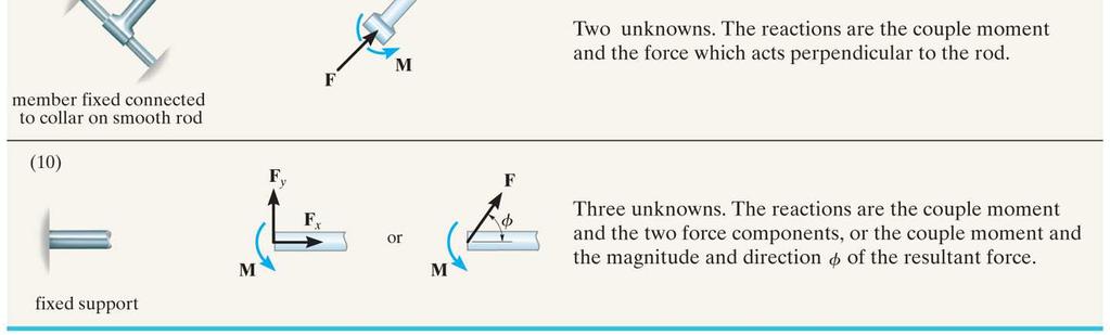
18 Example B Given:The load on the bent rod is supported by a smooth inclined surface at B and a collar at A. The collar is free to slide over the fixed inclined rod. Find: Support reactions at A and B Plan: a) Establish the x y axes b) Draw a complete FBD of the bent rod c) Apply the E-of-E to solve for the unknowns Example B - continued 100 lb M A 200 lb ft N A ft 3 ft FBD of the rod ft + F X = (4 / 5) N A (5 / 13) N B = 0 N B + F Y = (3 / 5) N A + (12 / 13) N B 100 = 0 Solving these two equations, we get N B = 82.5 lb and N A = 39.7 lb + M A = M A (12 / 13) N B 6 (5 /13) N B 2 = 0 M A = 106 lb ft Engr221 Chapter 5 18
 how many support reactions are there, b) is this problem statically determinate, and, c) is the structure stable?")
19 Questions 1. For this beam, how many support reactions are there and is the problem statically determinate? A) (2, Yes) B) (2, No) C) (3, Yes) D) (3, No) F F F F 2. For the given beam loading: a) how many support reactions are there, b) is this problem statically determinate, and, c) is the structure stable? A) (4, Yes, No) B) (4, No, Yes) C) (5, Yes, No) D) (5, No, Yes) Fixed support Pin joints F Questions 1. The three scalar equations F X = F Y = M O = 0, are equations of equilibrium in two dimensions. A) incorrect B) the only correct C) the most commonly used D) not sufficient 2. A rigid body is subjected to forces as shown. This body can be considered a member. A) single-force B) two-force C) three-force D) six-force Engr221 Chapter 5 19
20 Question 1. Which equation of equilibrium allows you to determine F B right away? A) F X = 0 B) F Y = 0 C) M A = 0 D) Any one of the above A X A B AY F B 100 lb Summary Apply equations of equilibrium to solve for unknowns Recognize two-force members Engr221 Chapter 5 20
21 Announcements Textbook Problem 5.44 The mobile crane has a weight of 120,000 lb and a center of gravity at G 1. The boom has a weight of 30,000 lb and a center of gravity at G 2. Determine the smallest angle of tilt θ of the boom, without causing the crane to overturn if the suspended load is W = 40,000 lb. Neglect the thickness of the tracks at A and B. θ = 26.4º Engr221 Chapter 5 21


22 Textbook Problem 5.45 The mobile crane has a weight of 120,000 lb and a center of gravity at G 1. The boom has a weight of 30,000 lb and a center of gravity at G 2. If the suspended load has a weight of W = 16,000 lb, determine the normal reactions at the tracks A and B. For the calculation, neglect the thickness of the tracks and take θ = 30º. R A = 40.9 kip R B = 125 kip Textbook Problem 5.50 The uniform rod of length L and weight W is supported on the smooth planes. Determine its position θ for equilibrium. Neglect the thickness of the rod. θ = tan -1 (.5cotψ -.5cotφ) Engr221 Chapter 5 22
23 Textbook Problem 5.52 The rigid beam of negligible weight is supported by two springs and a pin at A. If the springs are uncompressed when the load is removed, determine the force in each spring when the load P is applied. Also, compute the vertical deflection of the end at C. F B = 0.3P F C = 0.6P x C = 0.6P/k Textbook Problem 5.56 The rigid metal strip of negligible weight is uses as part of an electromagnetic switch. Determine the maximum stiffness k of the springs at A and B so that the contact at C closes when the vertical force developed there is 0.5 N. Originally the strip is horizontal as shown. k = 250 N/m Engr221 Chapter 5 23
24 Textbook Problem 5.57 Determine the distance d for placement of the load P for equilibrium of the smooth bar in the position θ as shown. Neglect the weight of the bar. d = a/cos 3 θ Summary Apply equations of equilibrium to solve for unknowns Recognize two-force members Engr221 Chapter 5 24

25 Announcements Today s Objectives Rigid Body Equilibrium in 3-D Identify support reactions in 3-D and draw a free body diagram Apply the equations of equilibrium Class Activities Applications Support reactions in 3-D Equations of equilibrium Examples Engr221 Chapter 5 25


26 Applications Ball-and-socket joints and journal bearings are often used in mechanical systems. How can we determine the support reactions at these joints for a given loading? Applications - continued The weights of the fuselage and fuel act through A, B, and C. How will we determine the reactions at the wheels D, E, and F? A 50 lb sign is kept in equilibrium using two cables and a smooth collar. How can we determine the reactions at these supports? Engr221 Chapter 5 26


27 Support Reactions in 3D - Table 5-2 As a general rule, if a support prevents translation of a body in a given direction, then a reaction force acting in the opposite direction is developed on the body. Similarly, if rotation is prevented, a couple moment is exerted on the body by the support. Support Reactions in 3D - continued Engr221 Chapter 5 27


28 Support Reactions in 3D - continued Support Reactions in 3D - continued Engr221 Chapter 5 28
29 Important Note A single bearing or hinge can prevent rotation by providing a resistive couple moment. However, it is usually preferred to use two or more properly aligned bearings or hinges. Thus, in these cases, only force reactions are generated and there are no moment reactions created. Equilibrium Equations in 3-D As stated earlier, when a body is in equilibrium, the net force and the net moment equal zero, i.e. F = 0 and M O = 0 These two vector equations can be written as six scalar equations of equilibrium. These are: F X = F Y = F Z = 0 M X = M Y = M Z = 0 The moment equations can be determined about any point. Usually, choosing the point where the maximum number of unknown forces are present simplifies the solution. Those forces do not appear in the moment equation since they pass through the point. Engr221 Chapter 5 29
30 Constraints for a Rigid Body Redundant Constraints: When a body has more supports than necessary to hold it in equilibrium, it becomes statically indeterminate. A problem that is statically indeterminate has more unknowns than equations of equilibrium. Are statically indeterminate structures used in practice? Why or why not? Improper Constraints Here, we have 6 unknowns but there is nothing restricting rotation about the x axis. In some cases, there may be as many unknown reactions as there are equations of equilibrium. However, if the supports are not properly constrained, the body may become unstable for some loading cases. Engr221 Chapter 5 30
31 Example A Given:The cable of the tower crane is subjected to an 840N force. A fixed base at A supports the crane. Find: Reactions at the fixed base A. Plan: a) Establish the x, y, and z axes b) Draw a FBD of the crane c) Write the forces using Cartesian vector notation d) Apply the E-of-E (vector version) to solve for the unknown forces Example A - continued r BC = {12 i + 8 j 24 k } m F = F [u BC ] N = 840 [12 i + 8 j 24 k] / ( ( 24 2 )) ½ = {360 i j 720 k} N F A = {A X i + A Y j + A Z k } N Engr221 Chapter 5 31
32 Example A - continued From the E-of-E we get, F + F A = 0 {(360 + A X ) i + (240 + A Y ) j + ( A Z ) k} = 0 Solving each component equation yields: A X = 360 N A Y = 240 N A Z = 720 N Example A - continued Sum the moments acting at point A: M = M A + r AC F = 0 i j k = M AX i + M AY j + M AZ k = = M AX i + M AY j + M AZ k i j = 0 M AX = kn-m M AY = kn-m M AZ = 0 Engr221 Chapter 5 32
33 a) Draw a FBD of the rod Example B Given: A rod is supported by a ball-and-socket joint at A, a journal bearing at B and a short link at C. Assume the rod is properly aligned. Find: The reactions at all the supports for the loading shown. Plan: b) Apply scalar E-of-E to solve for the unknowns Example B - continued A FBD of the rod: A Z Z B Z A y X A X 2 kn B X Y F C 1 kn Applying the scalar E-of-E in appropriate order, we get: M Y = 2 (0.2) F C (0.2) = 0 ; F Y = A Y + 1 = 0 ; M Z = 2 (1.4) + B X (0.8) = 0 ; F C = 2 kn A Y = 1 kn B X = 3.5 kn Engr221 Chapter 5 33
34 Example B - continued A FBD of the rod: A Z Z B Z A y X A X 2 kn B X Y F C 1 kn F X = A X = 0 ; M X = 2 (0.4) + B Z (0.8) + 1 (0.2) = 0 ; F Z = A Z = 0 ; A X = 1.5 kn B Z = 0.75 kn A Z = 1.25 kn Question If an additional couple moment in the vertical direction is applied to rod AB at point C, what will happen to the rod? A) The rod remains in equilibrium as the cables provide the necessary support reactions. B) The rod remains in equilibrium as the ball-and-socket joint will provide the necessary resistive reactions. C) The rod becomes unstable as the cables cannot support compressive forces. D) The rod becomes unstable since a moment about AB cannot be restricted. Engr221 Chapter 5 34
35 Question The rod AB is supported using two cables at B and a ball-and-socket joint at A. How many unknown support reactions exist in this problem? A) 5 force and 1 moment reaction B) 5 force reactions C) 3 force and 3 moment reactions D) 4 force and 2 moment reactions 1. If a support prevents rotation of a body about an axis, then the support exerts a on the body about that axis. A) couple moment B) force C) both A and B D) none of the above Questions 2. When doing a 3-D problem analysis, you have scalar equations of equilibrium. A) 2 B) 3 C) 4 D) 5 E) 6 Engr221 Chapter 5 35
36 Question A plate is supported by a ball-andsocket joint at A, a roller joint at B, and a cable at C. How many unknown support reactions are there in this problem? A) 4 forces and 2 moments B) 6 forces C) 5 forces D) 4 forces and 1 moment Question What will be the easiest way to determine the force reaction B Z? A) Scalar equation F Z = 0 B) Vector equation M A = 0 C) Scalar equation M Z = 0 D) Scalar equation M Y = 0 Engr221 Chapter 5 36
37 Summary Identify support reactions in 3-D and draw a free body diagram Apply the equations of equilibrium Announcements Engr221 Chapter 5 37

38 Textbook Problem 5.68 Due to an unequal distribution of fuel in the wing tanks, the centers of gravity for the airplane fuselage A and wings B and C are located as shown. If these components have weights W A = lb, W B = 8000 lb, and W C = 6000 lb, determine the normal reactions of the wheels D, E, and F on the ground. F D = 22.6 kip F E = 22.6 kip F F = 13.7 kip Example Problem Determine the x and z components of reaction at the journal bearing A and the tension in cords BC and BD necessary for equilibrium of the rod. A x = 0 N F BD = 208 N F BC = 792 N A Z = 0 N M AX = 0 Nm M AZ = 700 Nm Engr221 Chapter 5 38
39 Textbook Problem 5.84 Determine the x, y, and z components of reaction at the pin A and the tension in the cable BC necessary for equilibrium of the rod. F BC = 101 lb A Y = -140 lb A Z = 77.8 lb M AY = -389 lb-ft M AZ = 93.3 lb-ft Example Problem The boom AC is supported at A by a ball-and-socket joint and by two cables BDC and EC. Cable BDC is continuous and passes over a frictionless pulley at D. Calculate the tension in the cables and the x, y, and z components of reaction at A if the crate has a weight of 80 lb. Answer: Unknown Engr221 Chapter 5 39

40 Textbook Problem 5.72 The uniform table has a weight of 20 lb and is supported by the framework shown. Determine the smallest vertical force P that can be applied to its surface that will cause it to tip over. Where should this force be applied? P = 14.1 lb, at the corner of the table Summary Identify support reactions in 3-D and draw a free body diagram Apply the equations of equilibrium Engr221 Chapter 5 40
EQUILIBRIUM OF A RIGID BODY
 EQUILIBRIUM OF A RIGID BODY Today s Objectives: Students will be able to a) Identify support reactions, and, b) Draw a free diagram. APPLICATIONS A 200 kg platform is suspended off an oil rig. How do we
EQUATIONS OF EQUILIBRIUM & TWO- AND THREE-FORCE MEMBERS
 EQUATIONS OF EQUILIBRIUM & TWO- AND THREE-FORCE MEMBERS Today s Objectives: Students will be able to: a) Apply equations of equilibrium to solve for unknowns, and, b) Recognize two-force members. APPLICATIONS
ENGR-1100 Introduction to Engineering Analysis. Lecture 13
 ENGR-1100 Introduction to Engineering Analysis Lecture 13 EQUILIBRIUM OF A RIGID BODY & FREE-BODY DIAGRAMS Today s Objectives: Students will be able to: a) Identify support reactions, and, b) Draw a free-body
CHAPTER 2: EQUILIBRIUM OF RIGID BODIES
 For a rigid body to be in equilibrium, the net force as well as the net moment about any arbitrary point O must be zero Summation of all external forces. Equilibrium: Sum of moments of all external forces.
EQUATIONS OF EQUILIBRIUM & TWO-AND THREE-FORCE MEMEBERS
 EQUATIONS OF EQUILIBRIUM & TWO-AND THREE-FORCE MEMEBERS Today s Objectives: Students will be able to: a) Apply equations of equilibrium to solve for unknowns, and, b) Recognize two-force members. READING
Engineering Mechanics: Statics in SI Units, 12e
 Engineering Mechanics: Statics in SI Units, 12e 5 Equilibrium of a Rigid Body Chapter Objectives Develop the equations of equilibrium for a rigid body Concept of the free-body diagram for a rigid body
EQUATIONS OF EQUILIBRIUM & TWO- AND THREE-FORCE MEMEBERS
 EQUATIONS OF EQUILIBRIUM & TWO- AND THREE-FORCE MEMEBERS Today s Objectives: Students will be able to: a) Apply equations of equilibrium to solve for unknowns, and, b) Recognize two-force members. In-Class
EQUILIBRIUM OF A RIGID BODY & FREE-BODY DIAGRAMS
 Today s Objectives: Students will be able to: EQUILIBRIUM OF A RIGID BODY & FREE-BODY DIAGRAMS a) Identify support reactions, and, b) Draw a free-body diagram. In-Class Activities: Check Homework Reading
EQUATIONS OF EQUILIBRIUM & TWO- AND THREE-FORCE MEMBERS
 EQUATIONS OF EQUILIBRIUM & TWO- AND THREE-FORCE MEMBERS Today s Objectives: Students will be able to: a) Apply equations of equilibrium to solve for unknowns b) Identify support reactions c) Recognize
Chapter Objectives. Copyright 2011 Pearson Education South Asia Pte Ltd
 Chapter Objectives To develop the equations of equilibrium for a rigid body. To introduce the concept of the free-body diagram for a rigid body. To show how to solve rigid-body equilibrium problems using
STATICS. Bodies. Vector Mechanics for Engineers: Statics VECTOR MECHANICS FOR ENGINEERS: Design of a support
 4 Equilibrium CHAPTER VECTOR MECHANICS FOR ENGINEERS: STATICS Ferdinand P. Beer E. Russell Johnston, Jr. Lecture Notes: J. Walt Oler Texas Tech University of Rigid Bodies 2010 The McGraw-Hill Companies,
Engineering Mechanics Statics
 Mechanical Systems Engineering _ 2016 Engineering Mechanics Statics 7. Equilibrium of a Rigid Body Dr. Rami Zakaria Conditions for Rigid-Body Equilibrium Forces on a particle Forces on a rigid body The
Equilibrium of a Particle
 ME 108 - Statics Equilibrium of a Particle Chapter 3 Applications For a spool of given weight, what are the forces in cables AB and AC? Applications For a given weight of the lights, what are the forces
Equilibrium of a Rigid Body. Chapter 5
 Equilibrium of a Rigid Body Chapter 5 Overview Rigid Body Equilibrium Free Body Diagrams Equations of Equilibrium 2 and 3-Force Members Statical Determinacy CONDITIONS FOR RIGID-BODY EQUILIBRIUM Recall
EQUILIBRIUM OF RIGID BODIES
 EQUILIBRIUM OF RIGID BODIES Equilibrium A body in equilibrium is at rest or can translate with constant velocity F = 0 M = 0 EQUILIBRIUM IN TWO DIMENSIONS Case where the force system acting on a rigid
3.1 CONDITIONS FOR RIGID-BODY EQUILIBRIUM
 3.1 CONDITIONS FOR RIGID-BODY EQUILIBRIUM Consider rigid body fixed in the x, y and z reference and is either at rest or moves with reference at constant velocity Two types of forces that act on it, the
The case where there is no net effect of the forces acting on a rigid body
 The case where there is no net effect of the forces acting on a rigid body Outline: Introduction and Definition of Equilibrium Equilibrium in Two-Dimensions Special cases Equilibrium in Three-Dimensions
EQUATIONS OF EQUILIBRIUM & TWO- AND THREE-FORCE MEMEBERS
 EQUATIONS OF EQUILIBRIUM & TWO- AND THREE-FORCE MEMEBERS Today s Objectives: Students will be able to: a) Apply equations of equilibrium to solve for unknowns, and b) Recognize two-force members. In-Class
TUTORIAL SHEET 1. magnitude of P and the values of ø and θ. Ans: ø =74 0 and θ= 53 0
 TUTORIAL SHEET 1 1. The rectangular platform is hinged at A and B and supported by a cable which passes over a frictionless hook at E. Knowing that the tension in the cable is 1349N, determine the moment
Statics Chapter II Fall 2018 Exercises Corresponding to Sections 2.1, 2.2, and 2.3
 Statics Chapter II Fall 2018 Exercises Corresponding to Sections 2.1, 2.2, and 2.3 2 3 Determine the magnitude of the resultant force FR = F1 + F2 and its direction, measured counterclockwise from the
Chapter 5: Equilibrium of a Rigid Body
 Chapter 5: Equilibrium of a Rigid Body Chapter Objectives To develop the equations of equilibrium for a rigid body. To introduce the concept of a free-body diagram for a rigid body. To show how to solve
Ishik University / Sulaimani Architecture Department. Structure. ARCH 214 Chapter -5- Equilibrium of a Rigid Body
 Ishik University / Sulaimani Architecture Department 1 Structure ARCH 214 Chapter -5- Equilibrium of a Rigid Body CHAPTER OBJECTIVES To develop the equations of equilibrium for a rigid body. To introduce
Sample 5. Determine the tension in the cable and the horizontal and vertical components of reaction at the pin A. Neglect the size of the pulley.
 Sample 1 The tongs are designed to handle hot steel tubes which are being heat-treated in an oil bath. For a 20 jaw opening, what is the minimum coefficient of static friction between the jaws and the
Eng Sample Test 4
 1. An adjustable tow bar connecting the tractor unit H with the landing gear J of a large aircraft is shown in the figure. Adjusting the height of the hook F at the end of the tow bar is accomplished by
Equilibrium. Rigid Bodies VECTOR MECHANICS FOR ENGINEERS: STATICS. Eighth Edition CHAPTER. Ferdinand P. Beer E. Russell Johnston, Jr.
 Eighth E 4 Equilibrium CHAPTER VECTOR MECHANICS FOR ENGINEERS: STATICS Ferdinand P. Beer E. Russell Johnston, Jr. Lecture Notes: J. Walt Oler Texas Tech University of Rigid Bodies Contents Introduction
5.2 Rigid Bodies and Two-Dimensional Force Systems
 5.2 Rigid odies and Two-Dimensional Force Systems 5.2 Rigid odies and Two-Dimensional Force Systems Procedures and Strategies, page 1 of 1 Procedures and Strategies for Solving Problems Involving Equilibrium
Announcements. Trusses Method of Joints
 Announcements Mountain Dew is an herbal supplement Today s Objectives Define a simple truss Trusses Method of Joints Determine the forces in members of a simple truss Identify zero-force members Class
The centroid of an area is defined as the point at which (12-2) The distance from the centroid of a given area to a specified axis may be found by
 The distance from the centroid of a given area to a specified axis may be found by") Unit 12 Centroids Page 12-1 The centroid of an area is defined as the point at which (12-2) The distance from the centroid of a given area to a specified axis may be found by (12-5) For the area shown
Unit 12 Centroids Page 12-1 The centroid of an area is defined as the point at which (12-2) The distance from the centroid of a given area to a specified axis may be found by (12-5) For the area shown
Announcements. Equilibrium of a Particle in 2-D
 nnouncements Equilibrium of a Particle in 2-D Today s Objectives Draw a free body diagram (FBD) pply equations of equilibrium to solve a 2-D problem Class ctivities pplications What, why, and how of a
Statics - TAM 211. Lecture 14 October 19, 2018
 Statics - TAM 211 Lecture 14 October 19, 2018 Announcements Students are encouraged to practice drawing FBDs, writing out equilibrium equations, and solving these by hand using your calculator. Expending
Chapter - 1. Equilibrium of a Rigid Body
 Chapter - 1 Equilibrium of a Rigid Body Dr. Rajesh Sathiyamoorthy Department of Civil Engineering, IIT Kanpur hsrajesh@iitk.ac.in; http://home.iitk.ac.in/~hsrajesh/ Condition for Rigid-Body Equilibrium
Engineering Mechanics: Statics in SI Units, 12e
 Engineering Mechanics: Statics in SI Units, 12e 3 Equilibrium of a Particle 1 Chapter Objectives Concept of the free-body diagram for a particle Solve particle equilibrium problems using the equations
Equilibrium of a Rigid Body. Engineering Mechanics: Statics
 Equilibrium of a Rigid Body Engineering Mechanics: Statics Chapter Objectives Revising equations of equilibrium of a rigid body in 2D and 3D for the general case. To introduce the concept of the free-body
When a rigid body is in equilibrium, both the resultant force and the resultant couple must be zero.
 When a rigid body is in equilibrium, both the resultant force and the resultant couple must be zero. 0 0 0 0 k M j M i M M k R j R i R F R z y x z y x Forces and moments acting on a rigid body could be
Equilibrium of Rigid Bodies
 Equilibrium of Rigid Bodies 1 2 Contents Introduction Free-Bod Diagram Reactions at Supports and Connections for a wo-dimensional Structure Equilibrium of a Rigid Bod in wo Dimensions Staticall Indeterminate
11.1 Virtual Work Procedures and Strategies, page 1 of 2
 11.1 Virtual Work 11.1 Virtual Work rocedures and Strategies, page 1 of 2 rocedures and Strategies for Solving roblems Involving Virtual Work 1. Identify a single coordinate, q, that will completely define
Engineering Mechanics: Statics in SI Units, 12e
 Engineering Mechanics: Statics in SI Units, 12e 3 Equilibrium of a Particle Chapter Objectives To introduce the concept of the free-body diagram for a particle To show how to solve particle equilibrium
STATICS. Bodies VECTOR MECHANICS FOR ENGINEERS: Ninth Edition CHAPTER. Ferdinand P. Beer E. Russell Johnston, Jr.
 N E 4 Equilibrium CHAPTER VECTOR MECHANICS FOR ENGINEERS: STATICS Ferdinand P. Beer E. Russell Johnston, Jr. Lecture Notes: J. Walt Oler Texas Tech University of Rigid Bodies 2010 The McGraw-Hill Companies,
6.6 FRAMES AND MACHINES APPLICATIONS. Frames are commonly used to support various external loads.
 6.6 FRAMES AND MACHINES APPLICATIONS Frames are commonly used to support various external loads. How is a frame different than a truss? How can you determine the forces at the joints and supports of a
Lecture 14 February 16, 2018
 Statics - TAM 210 & TAM 211 Lecture 14 February 16, 2018 SoonTrending.com Announcements Structured office hours of working through practice problems will be held during Sunday office hours, starting Sunday
MEE224: Engineering Mechanics Lecture 4
 Lecture 4: Structural Analysis Part 1: Trusses So far we have only analysed forces and moments on a single rigid body, i.e. bars. Remember that a structure is a formed by and this lecture will investigate
ENGINEERING MECHANICS BAA1113
 ENGINEERING MECHANICS BAA1113 Chapter 3: Equilibrium of a Particle (Static) by Pn Rokiah Bt Othman Faculty of Civil Engineering & Earth Resources rokiah@ump.edu.my Chapter Description Aims To explain the
Equilibrium & Elasticity
 PHYS 101 Previous Exam Problems CHAPTER 12 Equilibrium & Elasticity Static equilibrium Elasticity 1. A uniform steel bar of length 3.0 m and weight 20 N rests on two supports (A and B) at its ends. A block
where x and y are any two non-parallel directions in the xy-plane. iii) One force equation and one moment equation.
 One force equation and one moment equation.") Concurrent Force System ( of Particles) Recall that the resultant of a concurrent force system is a force F R that passes through the point of concurrency, which we label as point O. The moment equation,
Concurrent Force System ( of Particles) Recall that the resultant of a concurrent force system is a force F R that passes through the point of concurrency, which we label as point O. The moment equation,
Chapter 5: Equilibrium of a Rigid Body
 Chapter 5: Equilibrium of a Rigid Body Develop the equations of equilibrium for a rigid body Concept of the free-body diagram for a rigid body Solve rigid-body equilibrium problems using the equations
ENGI 1313 Mechanics I
 ENGI 1313 Mechanics I Lecture 25: Equilibrium of a Rigid Body Shawn Kenny, Ph.D., P.Eng. Assistant Professor Faculty of Engineering and Applied Science Memorial University of Newfoundland spkenny@engr.mun.ca
Chapter 04 Equilibrium of Rigid Bodies
 Chapter 04 Equilibrium of Rigid Bodies Application Engineers designing this crane will need to determine the forces that act on this body under various conditions. 4-2 Introduction For a rigid body, the
Support Idealizations
 IVL 3121 nalysis of Statically Determinant Structures 1/12 nalysis of Statically Determinate Structures nalysis of Statically Determinate Structures The most common type of structure an engineer will analyze
Vector Mechanics: Statics
 PDHOnline Course G492 (4 PDH) Vector Mechanics: Statics Mark A. Strain, P.E. 2014 PDH Online PDH Center 5272 Meadow Estates Drive Fairfax, VA 22030-6658 Phone & Fax: 703-988-0088 www.pdhonline.org www.pdhcenter.com
EQUILIBRIUM OF A PARTICLE, THE FREE-BODY DIAGRAM & COPLANAR FORCE SYSTEMS
 EQUILIBRIUM OF PRTICLE, THE FREE-BODY DIGRM & COPLNR FORCE SYSTEMS Today s Objectives: Students will be able to : a) Draw a free body diagram (FBD), and, b) pply equations of equilibrium to solve a 2-D
7 STATICALLY DETERMINATE PLANE TRUSSES
 7 STATICALLY DETERMINATE PLANE TRUSSES OBJECTIVES: This chapter starts with the definition of a truss and briefly explains various types of plane truss. The determinancy and stability of a truss also will
EQUILIBRIUM OF RIGID BODIES IN TWO DIMENSIONS
 EQUILIBRIUM OF RIGID BODIES IN TWO DIMENSIONS If the resultant of all external forces acting on a rigid body is zero, then the body is said to be in equilibrium. Therefore, in order for the rigid body
Check Homework. Reading Quiz Applications Equations of Equilibrium Example Problems Concept Questions Group Problem Solving Attention Quiz
 THREE-DIMENSIONAL FORCE SYSTEMS Today s Objectives: Students will be able to solve 3-D particle equilibrium problems by a) Drawing a 3-D free body diagram, and, b) Applying the three scalar equations (based
ENGR-1100 Introduction to Engineering Analysis. Lecture 19
 ENGR-1100 Introduction to Engineering Analysis Lecture 19 SIMPLE TRUSSES, THE METHOD OF JOINTS, & ZERO-FORCE MEMBERS Today s Objectives: Students will be able to: In-Class Activities: a) Define a simple
Equilibrium Equilibrium and Trusses Trusses
 Equilibrium and Trusses ENGR 221 February 17, 2003 Lecture Goals 6-4 Equilibrium in Three Dimensions 7-1 Introduction to Trusses 7-2Plane Trusses 7-3 Space Trusses 7-4 Frames and Machines Equilibrium Problem
ME Statics. Structures. Chapter 4
 ME 108 - Statics Structures Chapter 4 Outline Applications Simple truss Method of joints Method of section Germany Tacoma Narrows Bridge http://video.google.com/videoplay?docid=-323172185412005564&q=bruce+lee&pl=true
Statics. Phys101 Lectures 19,20. Key points: The Conditions for static equilibrium Solving statics problems Stress and strain. Ref: 9-1,2,3,4,5.
 Phys101 Lectures 19,20 Statics Key points: The Conditions for static equilibrium Solving statics problems Stress and strain Ref: 9-1,2,3,4,5. Page 1 The Conditions for Static Equilibrium An object in static
Announcements. Principle of Work and Energy - Sections Engr222 Spring 2004 Chapter Test Wednesday
 Announcements Test Wednesday Closed book 3 page sheet sheet (on web) Calculator Chap 12.6-10, 13.1-6 Principle of Work and Energy - Sections 14.1-3 Today s Objectives: Students will be able to: a) Calculate
PLANAR KINETIC EQUATIONS OF MOTION: TRANSLATION
 PLANAR KINETIC EQUATIONS OF MOTION: TRANSLATION Today s Objectives: Students will be able to: 1. Apply the three equations of motion for a rigid body in planar motion. 2. Analyze problems involving translational
STATICS. FE Review. Statics, Fourteenth Edition R.C. Hibbeler. Copyright 2016 by Pearson Education, Inc. All rights reserved.
 STATICS FE Review 1. Resultants of force systems VECTOR OPERATIONS (Section 2.2) Scalar Multiplication and Division VECTOR ADDITION USING EITHER THE PARALLELOGRAM LAW OR TRIANGLE Parallelogram Law: Triangle
SIMPLE TRUSSES, THE METHOD OF JOINTS, & ZERO-FORCE MEMBERS
 SIMPLE TRUSSES, THE METHOD OF JOINTS, & ZERO-FORCE MEMBERS Today s Objectives: Students will be able to: a) Define a simple truss. b) Determine the forces in members of a simple truss. c) Identify zero-force
Name. ME 270 Fall 2005 Final Exam PROBLEM NO. 1. Given: A distributed load is applied to the top link which is, in turn, supported by link AC.
 Name ME 270 Fall 2005 Final Exam PROBLEM NO. 1 Given: A distributed load is applied to the top link which is, in turn, supported by link AC. Find: a) Draw a free body diagram of link BCDE and one of link
ENGR-1100 Introduction to Engineering Analysis. Lecture 23
 ENGR-1100 Introduction to Engineering Analysis Lecture 23 Today s Objectives: Students will be able to: a) Draw the free body diagram of a frame and its members. FRAMES b) Determine the forces acting at
PAT 101 FUNDAMENTAL OF ENGINEERING MECHANICS EQUILIBREQUILIBRIUM OF A RIGID BODY IUM OF A RIGID BODY
 PAT 101 FUNDAMENTAL OF ENGINEERING MECHANICS EQUILIBREQUILIBRIUM OF A RIGID BODY IUM OF A RIGID BODY MARDHIAH FARHANA BINT OMAR Week 5-6 EQUILIBRIUM OF A RIGID BODY Conditions for Rigid Equilibrium Free-Body
Engineering Mechanics: Statics. Chapter 7: Virtual Work
 Engineering Mechanics: Statics Chapter 7: Virtual Work Introduction Previous chapters-- FBD & zero-force and zero-moment equations -- Suitable when equilibrium position is known For bodies composed of
PLANAR KINETIC EQUATIONS OF MOTION: TRANSLATION
 PLANAR KINETIC EQUATIONS OF MOTION: TRANSLATION Today s Objectives: Students will be able to: 1. Apply the three equations of motion for a rigid body in planar motion. 2. Analyze problems involving translational
Chapter 6: Structural Analysis
 Chapter 6: Structural Analysis APPLICATIONS Trusses are commonly used to support a roof. For a given truss geometry and load, how can we determine the forces in the truss members and select their sizes?
TEST REPORT. Question file: P Copyright:
 Date: February-12-16 Time: 2:00:28 PM TEST REPORT Question file: P12-2006 Copyright: Test Date: 21/10/2010 Test Name: EquilibriumPractice Test Form: 0 Test Version: 0 Test Points: 138.00 Test File: EquilibriumPractice
VALLIAMMAI ENGINEERING COLLEGE SRM NAGAR, KATTANKULATHUR DEPARTMENT OF MECHANICAL ENGINEERING
 VALLIAMMAI ENGINEERING COLLEGE SRM NAGAR, KATTANKULATHUR 603203 DEPARTMENT OF MECHANICAL ENGINEERING BRANCH: MECHANICAL YEAR / SEMESTER: I / II UNIT 1 PART- A 1. State Newton's three laws of motion? 2.
Theory of structure I 2006/2013. Chapter one DETERMINACY & INDETERMINACY OF STRUCTURES
 Chapter one DETERMINACY & INDETERMINACY OF STRUCTURES Introduction A structure refers to a system of connected parts used to support a load. Important examples related to civil engineering include buildings,
E 490 FE Exam Prep. Engineering Mechanics
 E 490 FE Exam Prep Engineering Mechanics 2008 E 490 Course Topics Statics Newton s Laws of Motion Resultant Force Systems Moment of Forces and Couples Equilibrium Pulley Systems Trusses Centroid of an
Outline: Frames Machines Trusses
 Outline: Frames Machines Trusses Properties and Types Zero Force Members Method of Joints Method of Sections Space Trusses 1 structures are made up of several connected parts we consider forces holding
I B.TECH EXAMINATIONS, JUNE ENGINEERING MECHANICS (COMMON TO CE, ME, CHEM, MCT, MMT, AE, AME, MIE, MIM)
") Code.No: 09A1BS05 R09 SET-1 I B.TECH EXAMINATIONS, JUNE - 2011 ENGINEERING MECHANICS (COMMON TO CE, ME, CHEM, MCT, MMT, AE, AME, MIE, MIM) Time: 3 hours Max. Marks: 75 Answer any FIVE questions All questions
Code.No: 09A1BS05 R09 SET-1 I B.TECH EXAMINATIONS, JUNE - 2011 ENGINEERING MECHANICS (COMMON TO CE, ME, CHEM, MCT, MMT, AE, AME, MIE, MIM) Time: 3 hours Max. Marks: 75 Answer any FIVE questions All questions
Determine the resultant internal loadings acting on the cross section at C of the beam shown in Fig. 1 4a.
 E X M P L E 1.1 Determine the resultant internal loadings acting on the cross section at of the beam shown in Fig. 1 a. 70 N/m m 6 m Fig. 1 Support Reactions. This problem can be solved in the most direct
Static Equilibrium. University of Arizona J. H. Burge
 Static Equilibrium Static Equilibrium Definition: When forces acting on an object which is at rest are balanced, then the object is in a state of static equilibrium. - No translations - No rotations In
KINGS COLLEGE OF ENGINEERING ENGINEERING MECHANICS QUESTION BANK UNIT I - PART-A
 KINGS COLLEGE OF ENGINEERING ENGINEERING MECHANICS QUESTION BANK Sub. Code: CE1151 Sub. Name: Engg. Mechanics UNIT I - PART-A Sem / Year II / I 1.Distinguish the following system of forces with a suitable
Lecture 23. ENGR-1100 Introduction to Engineering Analysis FRAMES S 1
 ENGR-1100 Introduction to Engineering Analysis Lecture 23 Today s Objectives: Students will be able to: a) Draw the free body diagram of a frame and its members. FRAMES b) Determine the forces acting at
SOLUTION 8 1. a+ M B = 0; N A = 0. N A = kn = 16.5 kn. Ans. + c F y = 0; N B = 0
 8 1. The mine car and its contents have a total mass of 6 Mg and a center of gravity at G. If the coefficient of static friction between the wheels and the tracks is m s = 0.4 when the wheels are locked,
CEE 271: Applied Mechanics II, Dynamics Lecture 25: Ch.17, Sec.4-5
 1 / 36 CEE 271: Applied Mechanics II, Dynamics Lecture 25: Ch.17, Sec.4-5 Prof. Albert S. Kim Civil and Environmental Engineering, University of Hawaii at Manoa Date: 2 / 36 EQUATIONS OF MOTION: ROTATION
Mechanics of Materials
 Mechanics of Materials 2. Introduction Dr. Rami Zakaria References: 1. Engineering Mechanics: Statics, R.C. Hibbeler, 12 th ed, Pearson 2. Mechanics of Materials: R.C. Hibbeler, 9 th ed, Pearson 3. Mechanics
1. Replace the given system of forces acting on a body as shown in figure 1 by a single force and couple acting at the point A.
 Code No: Z0321 / R07 Set No. 1 I B.Tech - Regular Examinations, June 2009 CLASSICAL MECHANICS ( Common to Mechanical Engineering, Chemical Engineering, Mechatronics, Production Engineering and Automobile
THE WORK OF A FORCE, THE PRINCIPLE OF WORK AND ENERGY & SYSTEMS OF PARTICLES
 THE WORK OF A FORCE, THE PRINCIPLE OF WORK AND ENERGY & SYSTEMS OF PARTICLES Today s Objectives: Students will be able to: 1. Calculate the work of a force. 2. Apply the principle of work and energy to
Engineering Mechanics: Statics STRUCTURAL ANALYSIS. by Dr. Ibrahim A. Assakkaf SPRING 2007 ENES 110 Statics
 CHAPTER Engineering Mechanics: Statics STRUCTURAL ANALYSIS College of Engineering Department of Mechanical Engineering Tenth Edition 6a by Dr. Ibrahim A. Assakkaf SPRING 2007 ENES 110 Statics Department
MOMENT OF A COUPLE. Today s Objectives: Students will be able to. a) define a couple, and, b) determine the moment of a couple.
 define a couple, and, b) determine the moment of a couple.") Today s Objectives: Students will be able to MOMENT OF A COUPLE a) define a couple, and, b) determine the moment of a couple. In-Class activities: Check Homework Reading Quiz Applications Moment of a Couple
Today s Objectives: Students will be able to MOMENT OF A COUPLE a) define a couple, and, b) determine the moment of a couple. In-Class activities: Check Homework Reading Quiz Applications Moment of a Couple
Continuing Education Course #207 What Every Engineer Should Know About Structures Part B Statics Applications
 1 of 6 Continuing Education Course #207 What Every Engineer Should Know About Structures Part B Statics Applications 1. As a practical matter, determining design loads on structural members involves several
ME 230 Kinematics and Dynamics
 ME 230 Kinematics and Dynamics Wei-Chih Wang Department of Mechanical Engineering University of Washington Lecture 8 Kinetics of a particle: Work and Energy (Chapter 14) - 14.1-14.3 W. Wang 2 Kinetics
1. Please complete the following short problems.
 Name 1. Please complete the following short problems. For parts 1A and 1B, we will consider three M88 recovery vehicles pulling an M1 tank back onto the road as shown below. F2 F1 50 M88 #1 50 M88 #2 y
F R. + F 3x. + F 2y. = (F 1x. j + F 3x. i + F 2y. i F 3y. i + F 1y. j F 2x. ) i + (F 1y. ) j. F 2x. F 3y. = (F ) i + (F ) j. ) j
 i + (F 1y. ) j. F 2x. F 3y. = (F ) i + (F ) j. ) j") General comments: closed book and notes but optional one page crib sheet allowed. STUDY: old exams, homework and power point lectures! Key: make sure you can solve your homework problems and exam problems.
General comments: closed book and notes but optional one page crib sheet allowed. STUDY: old exams, homework and power point lectures! Key: make sure you can solve your homework problems and exam problems.
if the initial displacement and velocities are zero each. [ ] PART-B
![if the initial displacement and velocities are zero each. [ ] PART-B](/thumbs/86/94772448.jpg "if the initial displacement and velocities are zero each. [ ] PART-B") Set No - 1 I. Tech II Semester Regular Examinations ugust - 2014 ENGINEERING MECHNICS (Common to ECE, EEE, EIE, io-tech, E Com.E, gri. E) Time: 3 hours Max. Marks: 70 Question Paper Consists of Part- and
Set No - 1 I. Tech II Semester Regular Examinations ugust - 2014 ENGINEERING MECHNICS (Common to ECE, EEE, EIE, io-tech, E Com.E, gri. E) Time: 3 hours Max. Marks: 70 Question Paper Consists of Part- and
LOVELY PROFESSIONAL UNIVERSITY BASIC ENGINEERING MECHANICS MCQ TUTORIAL SHEET OF MEC Concurrent forces are those forces whose lines of action
 LOVELY PROFESSIONAL UNIVERSITY BASIC ENGINEERING MECHANICS MCQ TUTORIAL SHEET OF MEC 107 1. Concurrent forces are those forces whose lines of action 1. Meet on the same plane 2. Meet at one point 3. Lie
HATZIC SECONDARY SCHOOL
 HATZIC SECONDARY SCHOOL PROVINCIAL EXAMINATION ASSIGNMENT STATIC EQUILIBRIUM MULTIPLE CHOICE / 33 OPEN ENDED / 80 TOTAL / 113 NAME: 1. State the condition for translational equilibrium. A. ΣF = 0 B. ΣF
Course Overview. Statics (Freshman Fall) Dynamics: x(t)= f(f(t)) displacement as a function of time and applied force
 Dynamics: x(t)= f(f(t)) displacement as a function of time and applied force") Course Overview Statics (Freshman Fall) Engineering Mechanics Dynamics (Freshman Spring) Strength of Materials (Sophomore Fall) Mechanism Kinematics and Dynamics (Sophomore Spring ) Aircraft structures
Course Overview Statics (Freshman Fall) Engineering Mechanics Dynamics (Freshman Spring) Strength of Materials (Sophomore Fall) Mechanism Kinematics and Dynamics (Sophomore Spring ) Aircraft structures
SRSD 2093: Engineering Mechanics 2SRRI SECTION 19 ROOM 7, LEVEL 14, MENARA RAZAK
 SRSD 2093: Engineering Mechanics 2SRRI SECTION 19 ROOM 7, LEVEL 14, MENARA RAZAK SIMPLE TRUSSES, THE METHOD OF JOINTS, & ZERO-FORCE MEMBERS Today s Objectives: Students will be able to: a) Define a simple
To show how to determine the forces in the members of a truss using the method of joints and the method of sections.
 5 Chapter Objectives To show how to determine the forces in the members of a truss using the method of joints and the method of sections. To analyze the forces acting on the members of frames and machines
Kinematics. v (m/s) ii. Plot the velocity as a function of time on the following graph.
 ii. Plot the velocity as a function of time on the following graph.") Kinematics 1993B1 (modified) A student stands in an elevator and records his acceleration as a function of time. The data are shown in the graph above. At time t = 0, the elevator is at displacement x
Kinematics 1993B1 (modified) A student stands in an elevator and records his acceleration as a function of time. The data are shown in the graph above. At time t = 0, the elevator is at displacement x
Chapter 7: Bending and Shear in Simple Beams
 Chapter 7: Bending and Shear in Simple Beams Introduction A beam is a long, slender structural member that resists loads that are generally applied transverse (perpendicular) to its longitudinal axis.
Consider two students pushing with equal force on opposite sides of a desk. Looking top-down on the desk:
 1 Bodies in Equilibrium Recall Newton's First Law: if there is no unbalanced force on a body (i.e. if F Net = 0), the body is in equilibrium. That is, if a body is in equilibrium, then all the forces on
PROBLEMS ON EQUILIBRIUM OF PARTICLES
 O EQUILIBRIUM O PRICLES 1. ind the angle of tilt q with the horiontal so that the contact force at B will be one-half that at for the smooth clinder. (3/15) q?, contact force at B will be one-half that
MECHANICS OF MATERIALS. Prepared by Engr. John Paul Timola
 MECHANICS OF MATERIALS Prepared by Engr. John Paul Timola Mechanics of materials branch of mechanics that studies the internal effects of stress and strain in a solid body. stress is associated with the