Whatcom County Flood Control Zone District. Canyon Creek Alluvial Fan Risk Assessment
|
|
|
- Daniella Simpson
- 6 years ago
- Views:
Transcription
1 Whatcom County Flood Control Zone District Canyon Creek Alluvial Fan Risk Assessment Final Report September 2003
2 Whatcom County Flood Control Zone District Canyon Creek Alluvial Fan Risk Assessment Final Report September 2003 KWL File No.
3 SEPTEMBER 2003 WHATCOM COUNTY FLOOD CONTROL ZONE DISTRICT STATEMENT OF LIMITATIONS This document has been prepared by Kerr Wood Leidal Associates Limited (KWL) for the exclusive use and benefit of the Whatcom County Flood Control Zone District. No other party is entitled to rely on any of the conclusions, data, opinions, or any other information contained in this document. This document represents KWL s best professional judgement based on the information available at the time of its completion and as appropriate for the project scope of work. Services performed in developing the content of this document have been conducted in a manner consistent with that level and skill ordinarily exercised by members of the engineering profession currently practising under similar conditions. No warranty, expressed or implied, is made. KERR WOOD LEIDAL ASSOCIATES LTD.
4 CONTENTS EXECUTIVE SUMMARY...i 1. INTRODUCTION BACKGROUND CREEK HAZARDS WORK PROGRAM PROJECT TEAM RECENT DEBRIS FLOODS AND MITIGATIVE ACTIONS CANYON CREEK FAN DEBRIS FLOOD DEBRIS FLOOD ENGINEERING STUDIES EARLY 1990S CONSTRUCTION PROGRAM FLOOD LONG-TERM MANAGEMENT STRATEGIES HAZARD MAPPING PROPERTY BUY-OUT DEBRIS FLOOD RISK ANALYSIS INTRODUCTION DEBRIS FLOOD AND FLOOD HAZARDS DEBRIS FLOOD MODELLING POTENTIAL CONSEQUENCE POTENTIAL DEBRIS FLOOD RISKS RISK MITIGATION ALTERNATIVES INTRODUCTION LAND USE PLANNING AND DEVELOPMENT WARNING SYSTEMS WATERSHED MANAGEMENT ACTIONS DEBRIS FLOOD MITIGATION STRUCTURES PREFERRED RISK MITIGATION ALTERNATIVES SUMMARY AND RECOMMENDATIONS SUMMARY RECOMMENDATIONS REPORT SUBMISSION BIBLIOGRAPHY KERR WOOD LEIDAL ASSOCIATES LTD.
5 FIGURES TABLES 1-1 Location Map 1-2 Watershed Map 1-3 Canyon Creek Fan Map 2-1 Overview Map of Canyon Creek Watershed Aerial Photograph of Canyon Creek Fan Aerial Photograph of Canyon Creek Whistler Creek Confluence 2-4 Previous Canyon Creek Fan Hazard Zones 2-5 Whatcom County Proposed Buy-out Area on Canyon Creek 3-1 Canyon Creek Debris Flood Modelling Results For Design Event 3-2 Canyon Creek Debris Flood Hazard Zones 1-1 Work Program APPENDICES A Background Information on Debris Floods and Debris Flows B Photographs C Watershed Description D Aerial Photograph Analysis E Environmental Resource Values F Hydrologic Analysis G Debris Flood Probability and Magnitude KERR WOOD LEIDAL ASSOCIATES LTD.
6 Executive Summary
7 EXECUTIVE SUMMARY Whatcom Country Flood Control Zone District retained Kerr Wood Leidal Associates to investigate debris flood hazards at Canyon Creek and identify a range of mitigative measures for consideration. A debris flood is defined as a very rapid surging flow of water in a steep channel, heavily charged with debris. A debris flood represents a more hazardous geomorphic process than a pure water flood. The 1989 and 1990 events at Canyon Creek are categorized as debris floods. The investigation concludes that a large debris flood at Canyon Creek may result from an outbreak flood following breach of a temporary landslide dam. The most likely location for such a blockage is at the toe of either the Jim Creek earthflow or the Bald Mountain earthflow. The landslide dam would likely breach rapidly, causing an outbreak flood that would incorporate landslide debris and downstream channel debris. FLDWAV software was used to model the outbreak flood for different landslide dam heights. In consultation with Whatcom County, a 500-year return period was selected as a design criteria for debris floods at Canyon Creek. This is consistent with recent practice in British Columbia for creek hazards beyond pure water floods. The study concludes that a 500-year return period debris flood would have a peak discharge of approximately 25,000 cfs (700 m 3 /s) and a total sediment volume of approximately 150,000 yd 3 (115,000 m 3 ) at the Canyon Creek fan apex. The 1989 debris flood peak discharge is estimated at approximately 16,100 cfs (455 m 3 /s), with a debris volume of approximately 70,000 yd 3 (54,000 m 3 ). This corresponds to a return period of approximately 200 years (which is consistent with dendrochronologic evidence). The 1990 debris flood was significantly smaller but more damaging (its effects being exacerbated by a change in fan morphology after the 1989 debris flood). Debris flood runout on the Canyon Creek fan was modelled with FLO-2D software in order to estimate the flow depth and velocity on the fan for the design event. The model scenarios included existing conditions, berm removal, and a breach of the existing berm. The deposition of the design event was illustrated in map form (Figure 3-1). This map was used as a basis for defining three hazard zones on the fan (Figure 3-2). A wide range of mitigative measures was reviewed. It is concluded that the proposed buy-out would be an effective risk reduction measure because it incorporates most of the highest hazard land on the fan. It would be appropriate to develop site-specific land use regulations for the rest of the developed area on the basis of Figure 3-2. Consideration should be given to removing the lower two-thirds of the berm and using the riprap to reinforce the right bank adjacent to Canyon View Drive (subject to land ownership and jurisdictional constraints). A number of other mitigative measures are also identified for consideration in Section 4.6. These may be implemented by Whatcom County, with referral to other agencies where appropriate. KERR WOOD LEIDAL ASSOCIATES LTD. i
8 Section 1 Introduction
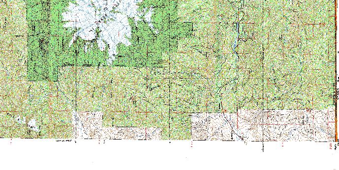
9 1. INTRODUCTION 1.1 BACKGROUND STUDY AREA Canyon Creek is a 31 mi 2 (79 km 2 ) watershed that discharges to the North Fork of the Nooksack River near the town of Glacier (Figure 1-1). Forestry is the primary land use within the watershed and extensive logging occurred from the 1960s to the 1980s. Poor logging practices and road construction resulted in numerous slope instabilities and significantly increased sediment supply to Canyon Creek. Much of the Canyon Creek fan is developed (Glacier Springs subdivision, the Logs Resort). Figure 1-2 shows the Canyon Creek watershed. A detailed map of the Canyon Creek fan is included as Figure AND 1990 DEBRIS FLOODS In November 1989, a large debris flood occurred on Canyon Creek. This event had a peak flow of approximately 16,100 cfs (455 m 3 /s) and destroyed one house on the fan. A smaller event in November 1990 destroyed three additional houses. A section (several hundred feet) of County road was also rendered unpassable. The extent of damage of the 1990 event was primarily due to aggradation on the upper fan from the 1989 debris flood. After the 1989 event, the US Soil Conservation Service constructed an armoured berm to protect the Glacier Springs Subdivision and the Mount Baker Highway. The berm was destroyed during the 1990 event. Whatcom County received disaster funding from the Federal Emergency Management Agency (FEMA) to construct a more extensive armoured berm. This berm was constructed in 1994 along the right (west) bank and extended from the fan apex to the creek mouth. CREEK MANAGEMENT ISSUES In the past decade, a number of studies have been conducted on Canyon Creek. These studies focussed on evaluating geomorphic processes and flooding, and identifying possible mitigative measures. Despite this work, Whatcom County felt that additional work was necessary to clarify the existing hazards and risks. As part of a long-term strategy, Whatcom County has received state and federal funding to acquire a number of undeveloped and developed lots on the active portion of the Canyon Creek fan. However, Whatcom County is concerned that future floods or debris floods could damage other development on the fan. The three main issues facing Whatcom County decision-makers are: KERR WOOD LEIDAL ASSOCIATES LTD. 1-1
10 1. Does the proposed buy-out adequately reduce the debris flood risk on the Canyon Creek fan? 2. What should be done with the existing berm? 3. Should development be restricted or prohibited in any areas of the fan and what would be considered appropriate mitigation measures should development continue? Whatcom County retained Kerr Wood Leidal Associates (KWL) to complete a detailed study of Canyon Creek to provide information that will enable the above three issues to be addressed. 1.2 CREEK HAZARDS Steep mountain creeks may be subject to geomorphic processes beyond pure water floods. Sediment and debris from watershed instability may provide the impetus for debris flows or debris floods. Some background information on debris floods and debris flows is provided in Appendix A. The 1989 and 1990 events at Canyon Creek have been previously described as debrisladen floods, debris floods, landslide dam break floods, dam burst floods, boulder floods, debris flows, and debris torrents, creating some confusion as to the true process. Based on descriptions and photographs of these events, they are best described as debris floods initiated by landslide dam outburst floods. DEFINITIONS According to Hungr et al. (2001), a debris flood is a very rapid, surging flow of water, heavily charged with debris, in a steep channel. The sediment may be transported in the form of massive surges, leaving sheets of poorly sorted debris ranging from sand to cobbles or small boulders. Sediment surges in a debris flood are propelled by the tractive forces of water overlying the debris and flow velocities are comparable to those of water floods. While debris floods carry an unusually high amount of sediment and/or organic debris, the concentration is not high enough to transform the event character from a flood to a landslide (e.g. debris flow). Debris floods are typically triggered by temporary channel blockages and discharges can be 2 to 5 times as high as water floods (Jakob and Jordan, 2001). From this definition, the terms debris-laden flood, dam burst flood, landslide dam break flood, and boulder flood are all appropriate descriptions of the Canyon Creek events. However, the term debris flood is preferred for consistency of terminology. The 1989 and 1990 Canyon Creek events are not classified as debris flows. A debris flow is a rapid flow of saturated non-plastic debris in a steep channel (Hungr et al., 2001). A debris flow is typically initiated by a point source failure that channelizes at impact with the main creek channel. A debris flow may reach up to 50 times the peak discharge KERR WOOD LEIDAL ASSOCIATES LTD. 1-2
11 of a 200-year return period clear water flood (Jakob and Jordan, 2001). Coarse-grained debris flows of the Pacific Northwest have sometimes been referred to locally as debris torrents, but the use of this term is discouraged. DEBRIS FLOWS VERSUS DEBRIS FLOODS This sub-section describes the principal differentiating characteristics between debris flows and debris floods. Debris floods can be distinguished from debris flows by water content. Debris floods may be visualized as an extension of the flood process with largely turbulent flow, whereas debris flows are more laminar due to a higher percentage of solids. Debris floods typically have a volumetric sediment concentration of 15% to 35%, whereas debris flows may have a sediment concentration of 45% to 75%. However, the water content of debris flows is highly variable due to the heterogeneity of debris flow surges and the transition from the bouldery front to the more fluid afterflow. Debris floods and debris flows can transition longitudinally downstream due to the bulking or debulking of channel sediment. There are two reasons that debris floods are considered the principal hazard on the Canyon Creek fan: 1. In the Pacific Northwest, debris flows typically occur in basins smaller than 2 mi 2 (5 km 2 ) where the mean channel gradient is greater than 18% (Hungr et al., 2001). At lower gradients, a debris flow typically loses momentum, begins to deposit, and then transforms into a debris flood. The average channel gradient of Canyon Creek is about 7% for a distance of 3.3 miles (5.3 km) above the fan apex. Above that point, the gradient averages 3%. Only a debris flow having a high clay content, such as a debris flow from a volcanic source area, could sustain flow on such a low gradient. A debris flow could initiate along several of the steep tributaries in the watershed, however, any tributary debris flow would likely deposit near the confluence with Canyon Creek. 2. The average gradient of the Canyon Creek fan (2.5%) is indicative of primarily fluvial processes rather than landslide activity. The stratigraphy of the fan supports this conclusion. Larger sub-rounded boulders are interbedded with fluvial sands and gravels, typical of debris flood deposition. Debris flow deposits are typically matrix supported, with subangular to angular boulders. Inverse grading (with the coarsest clasts on top) is observed in most coarse grained debris flow deposits. Furthermore, well confined debris lobes and levees, typical for debris flows are absent on the Canyon Creek fan. Debris floods are a poorly understood process because they are rarely observed and often occur as transient phenomena during debris flows. Debris floods can be caused by a variety of processes. A common process is breaching of a temporary stream blockage KERR WOOD LEIDAL ASSOCIATES LTD. 1-3
12 caused by a tributary debris flow or landslide. The discharge from an outbreak flood depends strongly on the composition and geometry of the landslide dam and the geometry of the downstream channel. The latter determines the degree to which a debris flood will attenuate before reaching the fan apex. Therefore, the above-noted typical range for debris flood discharge of 2 to 5 times the 200-year return period flood should only be used as a guideline (Hungr et al., 2001; Jakob and Jordan, 2001). 1.3 WORK PROGRAM OBJECTIVES The work program for this study was developed on the basis of the following primary objectives: investigate the history of debris floods quantify the debris flood hazard; review risk mitigation alternatives; identify appropriate mitigative actions; and define key issues associated with possible implementation of mitigation measures. With this information, Whatcom County can then consider implementation of mitigative measures at Canyon Creek. DESCRIPTION OF WORK PROGRAM The work program for this study is summarized in Table 1-1. Table 1-1 Work Program Work Task 1. Project Initiation Description 1.1 Project Initiation Meeting Review proposed work program and budget estimate. Confirm information sources and agency contacts. Obtain background information, including previous reports, digital maps, and other pertinent information. Discuss potential for further development on the fan and adjacent areas. Identify key stakeholders and discuss stakeholder involvement in project. Review project schedule and deliverables. 1.2 Background Information Review background information. Summarize background information for inclusion in report. KERR WOOD LEIDAL ASSOCIATES LTD. 1-4
13 Work Task 2. Air Photo Review and Mapping 3. Field Investigation 4. Technical Analyses Description 2.1 Air Photo Review Review complete aerial photograph chronosequence. Document historic watershed activity. Identify priority areas for field investigation. 2.2 Watershed Maps Transfer watershed information into GIS environment. Produce preliminary watershed and fan maps. 3.1 Watershed Investigation Perform helicopter survey (including still photography). Investigate logging-related and natural slope instabilities. Visit major sediment source areas. 3.2 Channel Investigation Traverse selected channel reaches. Obtain channel cross-sections at key locations. Evaluate potential landslide dam locations; estimate dam height and impoundment volume. Obtain dendrochronological (tree) samples for debris flood frequency analysis. 3.3 Fan Investigation Inspect existing dikes and bank protection works. Investigate potential for avulsions. Identify possible locations for mitigation structures. 4.1 Hydrologic Analysis Review previous hydrologic studies and peak flow estimates. Perform a brief hydrologic review to select design peak flows. Review available climate data to investigate long-term changes in rainfall frequency and magnitude. 4.2 Hazard Analysis Identify problems associated with past and future watershed activities. Estimate debris flood frequency from dendrochronology and previous studies. Estimate event magnitude (peak discharge and total volume). Establish frequency magnitude correlations. Model potential outbreak floods with FLDWAV. Model debris flood runout on fan for a 500-year return period event with FLO- 2D. Prepare multi-colour integrated hazard map for fan (to reflect existing conditions). 4.3 Consequence Analysis Document consequences of previous events. Consider potential consequence represented by buildings, roads and other infrastructure. Use hazard map to evaluate potential consequences of future events. KERR WOOD LEIDAL ASSOCIATES LTD. 1-5
14 Work Task 5. Preliminary Draft Report 6. Risk Mitigation Alternatives 7. Risk Mitigation Plan 8. Report Preparation Description 5.1 Prepare Draft Report Prepare preliminary draft report to document Tasks 1 to 4. Initial report review by project team. Submit draft report for review. 6.1 Risk Mitigation Objectives Select design events for risk mitigation. Consult with client to establish objectives for risk mitigation. Determine the need for active and/or passive risk mitigation measures. 6.2 Mitigative Structures Determine whether the proposed buy-out is an appropriate risk mitigation strategy. Determine the need for upgrading and/or modifying the existing berm. Determine the need for bank protection works on the outside of the berm. Identify potential environmental constraints and sensitivities. 6.3 Warning Systems Consider the applicability of various types of warning systems. 6.4 Watershed Management Actions Identify general watershed restoration measures to reduce watershed instability. Provide recommendations for future forestry operations. Consider the need for landslide stabilization and/or monitoring. 6.5 Land Use Planning Measures Provide input to ongoing land use regulation activities. Provide recommendations for floodproofing development on the fan. Provide input to anticipated highway upgrading. 7.1 Risk Mitigation Review Workshop to confirm risk mitigation objectives, review risk mitigation alternatives, and discuss applicability of each alternative. Refine risk mitigation alternatives based on workshop proceedings. 7.2 Preferred Alternative Select a preferred alternative. 8.1 Draft Report Prepare final draft report including mitigative measures. Initial report review by project team. Submit report to client for review. 8.2 Final Report Finalize report following feedback. Submit final report. KERR WOOD LEIDAL ASSOCIATES LTD. 1-6
15 REPORT FORMAT This report includes technical appendices that document specific parts of the investigation program (photographs, watershed description, aerial photograph analysis, environmental resource values, hydrology, and debris flood probability and magnitude assessment). Inclusion of most of the detailed technical content in the appendices allows the main report body to focus on the assessment and mitigation of debris flood risks. 1.4 PROJECT TEAM This report was written by Matthias Jakob, Ph.D., PG, Hamish Weatherly, M.Sc., PG, and Mike Currie, M.Eng., P.Eng. (BC), of KWL. The debris flood frequency and magnitude analysis was performed by Matthias Jakob. Hamish Weatherly of KWL completed the hydrologic investigation. Hamish Weatherly and Matthias Jakob performed the outbreak flood modelling and debris flood modelling on the fan. Input on behalf of Whatcom County was provided by Paula Cooper, PE, Paul Pittman, PG, Doug Goldthorp, PG, and Roger Nichols, Eng. Geol., of the U.S. Forest Service. The project also involved input from the Whatcom County River and Flood Committee and the Canyon Creek area residents (through a public information meeting on May 10, 2003). KERR WOOD LEIDAL ASSOCIATES LTD. 1-7


16 \Drawings\ StFig1-1.DWG Sep.24/03 Study Site Baseplan Source: MT.Baker, Wash. - B.C. Nw4 Concrete (NM10-12) 1:250,000 Scale Map N W12100/30x60 (1979) Canyon Creek Alluvial Fan Risk Assessment Whatcom County Flood Control Zone District September Scale in Metres Location Map Figure 1-1
17 \Drawings\ StFig1-2.CDR N BaseplanSource:1:69,500GreenTrails,Inc.MtBaker,Wa-No13(1996) Canyon Creek Alluvial Fan Risk Assessment Whatcom County Flood Control Zone District ProjectNo. 1 Date September Scale inmiles 1 Watershed Map Figure 1-2
18 \Drawings\ StFig1-3.DWG Sep.24/03 North Fork Nooksack River Mount Baker Highway (SR 542) Miller Way Miller Way Canyon View Drive Glacier Springs Glacier Springs Olsen Drive Drive Scott Pl. Kendra Ct. Canyon Fan Apex Logs Resort Creek Bedrock Canyon Bypass Channel 1995 Berm Breach Swimming Pool Ditch Flow During 1989, 1990 Events Canyon Creek Alluvial Fan Risk Assessment Whatcom County Flood Control Zone District Legend Armoured Berm Berm Property Line Former Shepherd Residence Limit of 1989,1990 Bank Erosion Fan Boundary Scale in Feet September 2003 Canyon Creek Fan Map Figure 1-3
19 Section 2 Recent Debris Floods and Mitigative Actions
20 2. RECENT DEBRIS FLOODS AND MITIGATIVE ACTIONS This section describes the recent debris flood events, and documents previous mitigative actions and studies at Canyon Creek. A description of the Canyon Creek fan is also provided. This section should be read in conjunction with Appendix B (photographs), Appendix C (watershed description), Appendix D (aerial photograph analysis), Appendix E (environmental resource values), Figure 2-1 (a geomorphic map of the watershed), and Figure 2-2 (a 2001 air photo of the Canyon Creek fan). 2.1 CANYON CREEK FAN The Canyon Creek fan began to form about 11,000 years ago, shortly after deglaciation of the North Fork Nooksack River valley. Fluvial deposition and episodic debris floods have created a fan with an area of approximately 220 acres (100 ha). Development on the fan commenced in the mid 1950s by the Ohlsen family, the original owners of the Logs Resort. The Glacier Springs subdivision was subsequently developed on the fan (Figure 1-3). Glacier Springs includes about 282 lots, a quarter of which are located north of the fan boundary. There are presently more than 40 houses on the fan. The fan apex is located at elevation of about 865 ft (260 m) where Canyon Creek emerges from the confines of a bedrock canyon. After the creek discharges from the canyon, it turns sharply to the left and continues to the southeast. Canyon Creek discharges to the North Fork Nooksack River approximately 900 ft (270 m) upstream of the Mount Baker Highway Bridge. The Glacier Springs subdivision is located on the right (west) bank approximately 30 ft (9 m) above the creek bed while the forested left (east) bank is situated 8 to 10 ft (2.4 to 3 m) above the creek bed. Below the sharp bend, the left bank is formed by the toe of the mountain and bedrock is exposed in places. The creek is separated from the right bank by a 20 ft to 30 ft (6 m to 9 m) high berm that was constructed in The fan reach of Canyon Creek is about 0.7 miles (1.1 km) long to the confluence with the North Fork Nooksack River (Photos 6, 7, and 8). The average channel gradient on the fan is 2.5%. The low flow channel is 15 ft (4.5 m) to 25 feet (7.5 m) wide, and the active channel ranges between 200 ft (60 m) and 450 ft (140 m) in width. During the 1989 debris flood, the active channel was completely inundated by water and debris and all vegetation was stripped. In the following decade, patchy vegetation has re-colonized within the active channel. In the past 50 years, the Glacier Springs subdivision has not been flooded. However, portions of the Logs Resort, which occupies a low lying area on the fan relative to the Glacier Springs subdivision, have been flooded. KERR WOOD LEIDAL ASSOCIATES LTD. 2-1
21 Other development on the fan includes the Mount Baker Highway, which roughly delineates the downstream edge of the fan. Much of the downstream end of the fan has been truncated by the North Fork Nooksack River, exposing massive debris flood sediments (Photo 11) DEBRIS FLOOD DESCRIPTION OF EVENT AND DAMAGE ON FAN The impetus for the present study was an extremely large flood event on November 9 and 10, 1989 that destroyed one house and threatened four others. Based on the flood description and the watershed characteristics, this event was a debris flood. A local resident, Mr. Shepherd, reported that 20 to 25 ft (7 to 8 m) of sediment was deposited in front of his house during the event (GeoEngineers, 1992). The Shepherd residence was situated about 1,000 ft (310 m) downstream of the fan apex along the right bank (by convention looking downstream). The 1989 event deposited an extremely large amount of sediment on the upper fan, as illustrated by Photo 1. The houses visible in the photo were destroyed by the 1990 event (Section 2.3). Overbank deposition associated with the 1989 event is still visible (Photo 12). Mr. Shepherd also reported seeing an 8 ft (2.4 m) high temporary debris dam in front of his house during the flooding (GeoEngineers, 1992). This dam broke and the material was transported downstream within a few minutes after he noticed it. The home that was destroyed was located upstream of Mr. Shepherd s residence on the right bank. No serious damage was sustained within the Logs Resort but localized flooding did occur. Some of the overflow through the Logs Resort followed an existing depression toward the Mount Baker Highway where it then flowed southeast to the North Fork Nooksack River following a ditch line located on the east side of the highway. Immediately following the flood, a contractor was hired to construct a 1,200 ft (360 m) long bypass channel that commenced at the fan apex (GeoEngineers, 1992). The bypass channel was positioned along the east margin of the fan in order to provide an overflow path away from existing development. PEAK FLOW ESTIMATE Representatives of the US Forest Service (USFS) estimated that the 1989 event had a peak flow of about 16,100 cfs (455 m 3 /s) at the mouth of the canyon. This estimate was based on the height of scour marks within the bedrock canyon (Photo 26). This estimate of the 1989 event peak flow is about three times large than the estimated 100-year return period water flood of 6,000 cfs (170 m 3 /s). In contrast, the peak flow about 4.5 miles (7.2 km) upstream of the fan apex was estimated to be only 3,060 cfs (87 m 3 /s). The dramatic increase in discharge between the two reaches, especially in the absence of KERR WOOD LEIDAL ASSOCIATES LTD. 2-2
22 intervening tributaries of significant size, indicates that the 1989 debris flood was the result of an outbreak flood from a landslide dam or a large log jam. DAMAGE IN UPPER WATERSHED While the debris flood that damaged the fan obviously initiated in the lower reaches, considerable damage also occurred in the mid to upper reaches of the watershed. The lower bridge of Road 31 was severely damaged (mile 5.2) and road sections immediately upstream and downstream of this point were washed away (Photo 2). The middle bridge crossing at Whistler Creek was also severely damaged, cutting off access to Road 3160 (Figure 2-1). Associated with the road damage was significant widening of the mainstem channel in unconfined reaches (Figures D-1 and D-2, Appendix D). The damage in the upper watershed appears to have been the result of outburst floods that initiated several hundred feet upstream of the confluence with Whistler Creek. According to Roger Nichols of the USFS, a snow avalanche (4,800 ft elevation) may have triggered a debris flow that blocked the mainstem channel at this location. A review of the 1991 air photos indicates that the debris flow initiated within a well-defined gully (Figure 2-3). However, there is no consensus that a snow avalanche triggered the debris flow. John Thompson (pers. comm.) noted that the snowpack at the Mount Baker ski area was only 2 to 2.5 ft (0.6 to 0.75 m) during the 1989 event and was therefore not likely sufficient for a snow avalanche to initiate. Whatever the origin, the resulting dam appears to have impounded sufficient water that a series of outburst floods occurred (Nichols observed four terraces upstream of the natural dam after the event). These outburst floods resulted in significant channel widening downstream and extensive scour of terrace deposits along the creek margin (Figure 2-3). Given the availability of abundant sediment within and adjacent to the channel, the outburst floods probably entrained sufficient sediment to be described initially as debris floods. However, the lack of confinement and relatively gentle channel gradient (approximately 3%) downstream of Whistler Creek probably transformed the event character to a flood by the time the peak flow reached the confluence with Kidney Creek (where there is no indication of an event of unusual magnitude). WATERSHED CONDITIONS Logging impacts may have been a factor in the extent of damage caused by the 1989 debris flood. Studies by Peak Northwest (1986) and Hale and Nichols (1994) documented about 100 landslides within the Canyon Creek watershed, most of which were associated with logging roads and clearcuts. About 50% of the sediment associated with the landslides (2.3 million yd 3 or 1.8 million m 3 ) is believed to have deposited in the mainstem channel of Canyon Creek. This documented increase in mass wasting frequency and magnitude may have amplified the potential for temporary dam formation and subsequent debris flood initiation. Appendix C provides more details on the landslide studies. KERR WOOD LEIDAL ASSOCIATES LTD. 2-3
23 1990 REPAIRS In January 1990, the US Soil Conservation Service (SCS, now the Natural Resource Conservation Service) made emergency repairs on the upper fan, placing riprap along the right (west) bank for a lineal distance of about 800 ft (240 m). The riprap had a maximum size of 5 ft (1.5 m) and was extended vertically down about 20 ft (6.1 m), which was thought to approximate the elevation of the creek bed prior to the 1989 event (GeoEngineers, 1992). The riprap was subsequently buried to a depth of 12 ft (3.7 m) to protect against scour. It was expected that moderate to low flows would scour a channel against or near the riprap. However, the original creek channel was not restored as part of the SCS riprap project and the flow was left in the bypass channel (GeoEngineers, 1992) DEBRIS FLOOD DESCRIPTION OF EVENT On the same date the following year, Canyon Creek experienced another debris flood. Sediment accumulated at the entrance to the bypass channel and the primary flow direction was toward the adjacent residences. Because the creek channel was not restored in conjunction with the SCS riprap project, there was little channel capacity for flood flow. Sediment deposited by the 1989 debris flood had filled most of the creek channel from the mouth of the bedrock canyon to the Shepherd residence and beyond. According to Mr. Shepherd, the 1990 event deposited an additional 5 ft (1.5 m) of sediment adjacent to his property. The creek flow subsequently overtopped the SCS riprap and rapidly incised laterally into the fan. The eroded area was about 200 ft (60 m) wide by 650 ft (200 m) long and severely damaged about 300 ft (90 m) of Canyon View Drive (Photo 3). An additional three houses were destroyed by the erosion and the eastern half of the Shepherd residence was undercut and later removed (Photo 4). Much of the SCS riprap was transported downstream. Mr. Ohlsen, the former owner of the Logs Resort, reported finding riprap in the North Fork Nooksack River about 2,500 ft (760 m) downstream. Again, the Logs Resort sustained only minor flooding with no significant damage. The 1990 event appears to have been another debris flood, but of significantly lower magnitude than the 1989 event. Mr. Shepherd is reported as stating that on the night of the 1990 event, the creek became quiet for a period of about three hours which was followed by a large explosion and a loud rush of water, causing him to abandon his house for the night (Ballerini, 1993a). This description is consistent with a debris flood initiated from an outbreak flood of a temporary dam. KERR WOOD LEIDAL ASSOCIATES LTD. 2-4
24 DENDROCHRONOLOGY Creek events can impact trees and leave scars, which subsequently overgrow. Cutting a wedge from this scar tissue allows the reconstruction of the year of damage. Coring a tree and counting back to a ring sequence that is very narrow enables the researcher to determine the date of the event. As described in Appendix G, a number of impact scars on trees upstream of the fan apex have been dated. The earliest recorded tree scar is A lack of scars for the 1990 event (compared to numerous for 1989) suggests a debris flood of significantly lower magnitude. 2.4 ENGINEERING STUDIES EARLY 1990S PURNELL AND ASSOCIATES, 1991 Following the 1989 and 1990 debris floods, Purnell and Associates (1991) were retained by the Glacier Springs Homeowners Association to address the potential erosion hazards to the subdivision. Based on a brief reconnaissance of the fan, Purnell identified three hazard zones where future erosion could occur (see Section 2.8). It was recommended that a comprehensive study of Canyon Creek be performed to assess the most useful and economical means of reducing the risk of future damage to the development. Purnell noted that such a study was beyond the scope of their reconnaissance. GLACIER SPRINGS FEASIBILITY STUDY, 1992 Following the Purnell report, Whatcom County retained GeoEngineers (1992) to determine the most cost-effective method of rebuilding and protecting Canyon View Drive and to assess the vulnerability of the Glacier Springs subdivision to damage from future events on Canyon Creek. GeoEngineers considered three primary options to protect against future flooding. The first two options involved channelizing any future events down to the North Fork Nooksack River. Option 1 Option 2 Option 3 With this option, a heavily armoured berm would be constructed near the mouth of the canyon to divert flow into the diversion channel. Berms on both sides of Canyon Creek would then confine the flow to the North Fork. Option 2 is similar in that berms would be constructed on both sides of the creek to channelize the flow. It differs in that the upper berms would follow the channel as repaired by the SCS. The right bank would be armoured about 30 ft (9 m) vertically while the left berm would be lower (20 ft, 6 m). A lower left bank would favour overflow to the inside of the bend, away from development. The third option was to construct a berm along the same alignment as the 1990 SCS revetment. The berm would extend slightly farther upstream and downstream than the SCS section and would be armoured with riprap to the KERR WOOD LEIDAL ASSOCIATES LTD. 2-5
25 top of the bank. It was recommended that the ground surface behind the left bank be horizontal or slope downward for a perpendicular distance of at least 100 ft (30 m) for the length of the berm. The sloped surface would allow for an overflow area in the event of peak flows. Because of high cost and the potential liability to Whatcom County from unforeseen consequences (due to significant changes to the geomorphic and hydraulic character of Canyon Creek), GeoEngineers did not recommend either of the channelization options. A do nothing scenario was not recommended as it was thought highly likely that future peak flow events could overtop the right bank in the vicinity of the former Shepherd residence and flow to the southwest REPAIRS Whatcom County approached FEMA (Federal Emergency Management Agency) to determine whether funding could be obtained for the creek works on Canyon Creek after the 1990 debris flood. FEMA reviewed the project and recommended that detailed discussion and a cost benefit analysis of repair options be completed prior to approval of the selected option. This request resulted in a second report by GeoEngineers dated April 5, In that report, two additional repair options were considered (Options 4 and 5). Option 4 was very similar to Option 3 and involved: constructing a 20 to 30 ft (6 to 9 m) high armoured berm on the right bank of the upper fan; placing the base of the riprap about 10 ft (3 m) below the creek bed to protect against potential scour; moving the creek further east into its position prior to the 1989 debris flood; constructing 10 to 15 ft high unarmoured berms on both banks in lower reaches to provide protection to the Logs Resort and the Mount Baker Highway (Option 3 provided no such provision); blasting a channel through a rock point located upstream of the Logs Resort (the exposed bedrock tended to deflect flows toward the Logs Resort during high flows); fish habitat restoration in the upper channel; riparian planting; and constructing groynes on the upper channel to reduce flows against the armoured right berm. Also considered was Option 5, which involved the buy-out of all Glacier Spring properties potentially affected by future creek events. GeoEngineers and Whatcom County considered Option 4 to be the most beneficial and cost-effective option for repair of existing flood damage and protection against future damage. KERR WOOD LEIDAL ASSOCIATES LTD. 2-6
26 CONSTRUCTION PROGRAM PROGRAM DESCRIPTION Between June 13 and November 17, 1994 most of the elements of Option 4 were constructed by Whatcom County using funds from FEMA (GeoEngineers, 1995). The final design involved construction of a 20 to 30 ft (6 to 9 m) high armoured berm on the right bank over a lineal distance of 2,400 ft (730 m). The berm was tied into high ground near the fan apex (Photo 5). Riprap was only placed on the river side of the berm and a low inset floodplain was constructed against the toe of the armoured berm (Photo 9). The installed riprap rock had an average size of 4.9 ft (1.5 m) and was designed for a 100-year return period peak flow of 5,000 cfs (142 m 3 /s) (GeoEngineers, 2000). GeoEngineers (2000) expressed the opinion that flood flow in Canyon Creek in excess of 5,000 cfs is extremely unlikely. This statement contradicts the USFS derived peak flow estimate of 16,100 cfs (455 m 3 /s) for the 1989 event (Richardson, 1990). Below the riprapped section, the berm was extended downstream a further 450 ft (137 m) to provide additional protection to the Logs Resort. However, this section of the berm was not armoured (Figure 1-3). The proposed berm on the left bank in the lower reaches was eliminated as a contract item because it was felt that the existing natural bank provided adequate flow deflection. Elimination of the left berm also provided additional area for sediment deposition during peak flow events. Additional measures included the construction of five groynes in the upper channel, blasting through the bedrock deflector, reconstruction of Canyon Drive, and the installation of instream fish habitat enhancements. Input for the fish habitat enhancements was received from the Lummi Indian Nation, Nooksack Indian Tribe, the USFS, and the Washington State Department of Fisheries. However, this input was not acted upon as it was requested that the channel be allowed to adjust before enhancement took place (Nichols, pers. comm.). SHORELINE PERMIT Before proceeding with construction, Whatcom County filed an application for a shoreline substantial development permit. The permit was filed with the Whatcom County Hearing Examiner and was required prior to commencing the recommended works. In the decision by the Examiner (file # SHS ), Conclusion of Law #1 stated that The dike or levee proposal is a reasonable interim step for moving toward a long-term solution. One of the conditions approving the shoreline permit prohibited routine maintenance without new permits. At the hearing, the Washington State Department of Ecology agreed to support the proposed berm as a temporary measure. In their view, the primary purpose of the berm was to protect against potential avulsion through Glacier Springs to the Mount Baker Highway. At the same time, the Department of Ecology strongly encouraged Whatcom KERR WOOD LEIDAL ASSOCIATES LTD. 2-7
27 County to develop and pursue a buy-out or relocation of the alluvial fan hazard area properties and to cease approving new building permits. Furthermore, the Department of Ecology stated that the only long-term solution is to relocate all occupants of the alluvial fan and to re-route the Mount Baker Highway to the fan apex of Canyon Creek (letter dated January 24, 2001 from Mr. Barry Wegner of the Department of Ecology to Mr. Doug Goldthorp of Whatcom County Planning & Development Services) FLOOD The 1994 works were tested by a relatively high peak flow in November A description of this event indicates that it was a predominantly water flood rather than a debris flood. Nonetheless, reported flood damage included the following (GeoEngineers, 1997): extensive erosion of the low flow floodplain adjacent to the armoured berm in the upper reach; breaching of the unarmoured berm near the Logs Resort (piping was observed prior to failure); damage to three of the groynes and the complete break-up of the other two; localized piping in the upper reach; and burial or removal of all fish enhancement structures. Some scour was also reported in the upper channel, and 3 to 6 ft (1 to 2 m) of aggradation occurred in the lower reach. Aggradation associated with the 1995 event extended into the North Fork Nooksack River and created a partial blockage (the sediment delivery exceeded the transport capacity of the North Fork flows). The partial blockage was sufficient to cause left bank erosion and there was concern for potential undermining of the Mount Baker Highway east bridge abutment. The North Fork Nooksack River has since mobilized and truncated distal portions of the fan. The partial blockage can possibly be attributed to the berm construction on Canyon Creek, which confines the channel and reduces the potential area of both overflows and sediment deposition. 2.7 LONG-TERM MANAGEMENT STRATEGIES 1999 INTER-FLUVE REPORT Whatcom County was eligible to receive additional FEMA funding to repair the riprap along the berm toe and reconstruct the groynes. However, the County was unable to utilize the funding before it expired in 1998, primarily due to a complete turnover in the River and Flood Section Staff and permitting issues associated with the Endangered Species Act (ESA). This was prior to the ESA listing of spring chinook and bull trout in Because both of these species reside in Canyon Creek, the permitting of berm KERR WOOD LEIDAL ASSOCIATES LTD. 2-8
28 repairs since the listing is expected to be even more difficult. Even with the existing minor damage, the structure is considered active in the Army Corps of Engineers PL Program. At this point, Whatcom County decided to re-evaluate the long-term management strategy for hazard mitigation on the Canyon Creek fan. In early 1999, Whatcom County retained Inter-Fluve to develop and evaluate long-term hazard mitigation strategies. Inter-Fluve (1999) identified a number of broad alternatives that address alluvial fan management within the deposition zone (i.e. the fan). Management approaches within the source zone (i.e. slopes within the watershed that supply sediment to the channel) were not discussed in detail as reasonable approaches to control sources have already been or are currently being addressed. Management approaches within the transport zone (i.e. the channel above the fan apex) were not addressed due to access issues and feasibility. Four general alternatives were presented in the Inter-Fluve report: 1. No action with maintenance of existing structures. 2. Property purchase. 3. Strengthen the existing armoured berm, extend it further downstream, and raise it in lower reaches. 4. Construction of a debris basin at the fan apex to store sediment during peak flow events. The 1999 report does not recommend a specific approach, but rather states that the following items should be considered in any decision: all properties on the fan are potentially at long-term risk, including the Mount Baker Highway; channel processes on alluvial fans are unpredictable and defy quantification, therefore, any structural approaches will require perpetual maintenance; confinement of the channel will promote further development on the fan and thereby increase the risk and potential for significant loss of property; and channel confinement alone does not address long-term aggradation, only a debris basin approach, which requires sediment removal and maintenance, will address long-term sedimentation on the fan. This report resulted in discussion about mitigative measures, but no immediate action was initiated REPORT As a second phase to the 1999 report, Whatcom County requested that Inter-Fluve (2000) provide concept level designs and cost estimates for five project alternatives: KERR WOOD LEIDAL ASSOCIATES LTD. 2-9
29 1. Repair and maintain the existing armoured berm upstream of the Logs Resort (Alternative 1b also considered the purchase of the resort). 2. Repair and maintain the existing berm with extension and realignment downstream to improve protection of the Logs Resort. 3. Relocate the armoured berm to the west and downstream extension of the relocated berm. 4. Acquire all riverside property on a short-term basis and acquire all potentially at-risk property on a long-term basis. 5. No action. For each of the above alternatives, Inter-Fluve assessed the expected level of performance for various flood events. This assessment involved hydraulic analyses to determine whether the armoured berm could be damaged by future large flood events. Using a design flow of 15,000 cfs (425 m 3 /s), the average velocity in the upper channel was estimated at 24.9 ft/s (7.6 m/s). Under these flow conditions, it was concluded that riprap with a median size of 10 ft (3 m) and a maximum size of 16 ft (5 m) would be required on the outside of the bend in the upper reach. Preliminary hydraulic analyses also indicated that the height of the existing berm would have provided about 10 ft (3 m) of freeboard for the 1989 event at the channel bend. However, it was noted that the calculations did not consider the potential for significant sediment deposition or superelevation of flow at the channel bend. Based on the above results, Inter-Fluve concluded that the riprap along the upper berm could not have withstood the peak flows experienced during the 1989 event. The riprap installed in 1994 had a maximum size of approximately 5.6 ft (1.7 m) and an average diameter of 4.9 ft (1.5 m). However, Inter-Fluve note that the required size of rock for a discharge of 15,000 cfs (425 m 3 /s) is essentially unfeasible with respect to material availability and construction. Inter-Fluve also completed hydraulic analyses for Alternative 3 where the natural embankment lying approximately 200 ft (60 m) behind the existing berm was assumed to be armoured (and the berm was removed). Based on this topography, the estimated flow velocity was 16.4 ft/s (5 m/s) with a recommended mean diameter of 4.6 ft (1.4 m) for riprap on the outside of the channel bend. In summary, Inter-Fluve concluded that: berm repair and extension will be susceptible to significant damage during moderate to extreme flood events, and risks to properties will remain moderate for flood events; alternatives 4 (property purchase) and 5 (no action) fail to address risks to the Mount Baker Highway in the event of a major channel avulsion; the highest level of long-term protection to both the highway and properties is Alternative 3 - the relocation and extension of the berm; and KERR WOOD LEIDAL ASSOCIATES LTD. 2-10
30 berm relocation is the most costly alternative evaluated ($1 million) and its performance will perpetually rely on monitoring and maintenance. The results of Inter-Fluve s study was presented to the Whatcom County Flood Control Zone District Advisory Committee (FCZDAC). After consideration of the long-term risks and costs associated with protecting development on the fan, the FCZDAC recommended the County pursue funding for a buy-out project and limit new development on the fan. In recent years, Whatcom County staff have worked with the County Council and the community to develop a buy-out project to mitigate hazards on the highest risk portion of the fan (see Section 2.9). 2.8 HAZARD MAPPING The reports by Purnell and Associates, GeoEngineers and Inter-Fluve included hazard mapping of the fan. The hazard zones identified were in the event that no further action was taken to protect against future debris floods and floods. PURNELL AND ASSOCIATES Purnell and Associates identified three hazard zones on the fan where future erosion could occur (Figure 2-4). Each of the hazard zones was assigned a level of risk and are defined as follows: Hazard Zone 1 Hazard Zone 2 Hazard Zone 3 This zone was identified as the most likely area where future damage to the subdivision could occur due to ongoing erosion. The hazard area encompasses twice the cumulative erosion area of the 1989 and 1990 events. Zone 1 was defined as an area of immediate or high erosion risk. Zone 2 is located along the southeast portion of the subdivision and includes an intermittent stream that runs along high ground. The headwall of the intermittent stream was observed to erode to the north when flowing. In the event the headwall of the intermittent stream reached the main channel of Canyon Creek, a major shift of Canyon Creek to the west was thought to be possible. Zone 2 was identified as a low risk area, although significant alteration to the creek could increase the risk. The potential hazard of Zone 3 was delineated on the basis of a low point in the side of the bank where some overspillage reportedly flowed during the 1990 event. Purnell and Associates felt that significant overflows from Canyon Creek could occur if a debris dam formed in KERR WOOD LEIDAL ASSOCIATES LTD. 2-11
31 GEOENGINEERS the vicinity of the bank. Zone 3 was defined as an intermediate risk zone. GeoEngineers (1992) divided the fan into five zones with three risk levels (Figure 2-4). The identified risk zones predate the berm design and construction (also true for Purnell). The zones are defined as follows: Low Risk Moderate Risk High Risk It is unlikely that the zone will be damaged during a flood similar in magnitude to the 1989 event (design flood). The zone might be damaged during a flood similar in magnitude to the 1990 event and will probably be damaged during a design flood. There is a better than average chance that damage will occur during a flood of 1990 magnitude and some damage will almost certainly occur from the design flood. INTER-FLUVE Inter-Fluve (2000) defined two buy-out zones on the fan. Zone 1 includes properties at short-term risk while properties within Zone 2 are at long-term risk. Properties identified at short-term risk include those properties that are currently located on the active fan margin, as well as those that lie within approximately 200 ft (60 m) of the active fan margin in the upper reach where westward channel migration has been most active. These properties include: a large section of the Logs Resort; Lots 3-18 of Block 1, Division 2, Glacier Springs Subdivision; and Lots 2-12 of Block 7, Division 2, Glacier Springs Subdivision. 2.9 PROPERTY BUY-OUT Based on the conclusions presented by Inter-Fluve and the hazard mapping, Whatcom County felt that continued maintenance of the existing berm would not provide an adequate level of long-term protection to Glacier Springs, given the number of residences that ultimately could be constructed on the fan. The County subsequently submitted a Hazard Mitigation Grant Application to FEMA to acquire properties adjacent to the active portion of the fan. The proposed buy-out would include the acquisition (and removal) of four properties with single family residences and the Logs Resort with seven structures (Figure 2-5). The buy-out cost is estimated at $1 million. As of April 2003, Whatcom County had received notice that their buy-out grant application had been approved. KERR WOOD LEIDAL ASSOCIATES LTD. 2-12
32 The buy-out project is being planned in partnership with the Whatcom Land Trust (WLT). The WLT has been awarded grant funding from the Salmon Recovery Funding Board to purchase undeveloped lots in the high-risk area and the Logs Resort lands. KERR WOOD LEIDAL ASSOCIATES LTD. 2-13
33 NATIONAL FOREST BOUNDARY 1989 Debris Flow mpcv AD RO 12 Reach 10 ch Rea Bald Mountain 1 ch 1 Rea CANYON 1989 Debris Flow Dam Re ac h9 Cre ek Alluvial Fan Topography Index Contour Intermediate Contour M ou nta in Bearpaw Church Lake RO AD Wh istl er Kid ney Rea ch 7 Lakes Road Gravel Road RO AD Trail Transmission Line Vegetation Marsh Mass Movement Processes and Landforms Whistler Lake Creek Watershed Boundary Sub-Watershed Boundary Re ac h6 Wa ters he d Infrastructure eek Cr Mtn. Lake Damfino Bearpaw Mountain Ts Cre ek Lake PMel h8 ac Re Bald Mountain Earthflow Ba ld Creek EK CRE LT FAU EEK CR Bald JIM mpcs Bank Full Stream Channel Reach 13 ROAD Ts Hydrologic Landforms Re ac h5 ek Jim Cre Church Mountain Jim Creek Earthflow h4 ac Re Area of Potential Landslide Initiation that could block Canyon Creek Watershed Debris Avalanche/Debris Flow (Select Events) Geology in the Earthflow Vicinity After Brown et al., 1987 Jim 3 ch Rea Creek Ts h2 ac Re D NE DO AN AB Logs Resort RO AD ON NY CA Sep.24/03 FOREST mpcs Chilliwack Sedimentary Rocks mpcv Chilliwack Volcanic Rocks PMel Elbow Lake Formation Fault (Approximate) RO AD Glacier Springs Landslide Dam Outbreak Modelling Location CR EEK ROAD Tertiary Sedimentary Rocks (Mostly Chuckanut Formation) Geologic Contact (Approximate) Earthflow (Boundaries Approximate) Douglas Fir Campground (ROAD 31) th For Nor k Noo k sack River Glacier MOUN T BAKE R HIG HWAY Gla cie r \Drawings\ StFig2-1.DWG ek Cre Canyon Creek Alluvial Fan Risk Assessment Overview Map of Canyon Creek Watershed Scale in Miles 0.5 Figure 2-1

34 North Fork Nooksack River Canyon Creek \Drawings\ StFig2-2.Dwg Sep.24/03 Baseplan Source: Washington State Department of Natural Resources. September 10, Project NW-C-0, Roll 73-58, Photo 217 September Approx. Scale in Feet Canyon Creek Alluvial Fan Risk Assessment Whatcom County Flood Control Zone District 2001 Aerial Photograph of Canyon Creek Fan Figure 2-2

35 N Canyon Creek 1989 Landslide Dam \Drawings\ StFig2-3 Sep.24/03 Baseplan Source: United States Forest Service. July 22, Project C, Roll 691, Photo September Approx. Scale in Feet 1000 Whistler Creek Canyon Creek Alluvial Fan Risk Assessment Whatcom County Flood Control Zone District 1991 Aerial Photograph of Canyon Creek - Whistler Creek Confluence Figure 2-3
The last three sections of the main body of this report consist of:
 Threatened and Endangered Species Geological Hazards Floodplains Cultural Resources Hazardous Materials A Cost Analysis section that provides comparative conceptual-level costs follows the Environmental
1 INTRODUCTION AND MAJOR FINDINGS... 1
 Memorandum To: Lindsey Clark, Stillwater Valley Watershed Council Coordinator From: Chad Raisland, Pioneer Technical Services, Inc. and Karin Boyd, Applied Geomorphology, Inc. CC: Tanya Lester, Stillwater
Swift Creek Sediment Management Action Plan (SCSMAP)
") Swift Creek Sediment Management Action Plan (SCSMAP) PHASE 2 PROJECT PLAN PROPOSAL Whatcom County Public Works Department 322 N. Commercial Street, Suite 210 Bellingham, WA 98225 (360) 676-6692 June 2013
Swift Creek Sediment Management Action Plan (SCSMAP) PHASE 2 PROJECT PLAN PROPOSAL Whatcom County Public Works Department 322 N. Commercial Street, Suite 210 Bellingham, WA 98225 (360) 676-6692 June 2013
APPENDIX A REACH DECRIPTIONS. Quantico Creek Watershed Assessment April 2011
 APPENDIX A REACH DECRIPTIONS Basin 615, South Fork of Quantico Creek - Project Reach Descriptions Reach Name: 615-A Coordinates (NAD 83, Virginia State Plane North): 11796510.57, 6893938.95 to 11801555.79,
Project (Project No. US-CA-62-2) Maintenance Inspection and Reports (Subtask 14.1) Inspection Report No.2
 Maintenance Inspection and Reports (Subtask 14.1) Inspection Report No.2") MEMORANDUM TO: FROM: Jim Well, Ducks Unlimited Mike Harvey, PhD, PG SUBJECT: M&T/ Llano Seco Fish Screen Project (Project No. US-CA-62-2) Maintenance Inspection and Reports (Subtask 14.1) Inspection Report
MEMORANDUM TO: FROM: Jim Well, Ducks Unlimited Mike Harvey, PhD, PG SUBJECT: M&T/ Llano Seco Fish Screen Project (Project No. US-CA-62-2) Maintenance Inspection and Reports (Subtask 14.1) Inspection Report
PENNSYLVANIA DEPARTMENT OF TRANSPORTATION ENGINEERING DISTRICT 3-0
 PENNSYLVANIA DEPARTMENT OF TRANSPORTATION ENGINEERING DISTRICT 3-0 LYCOMING COUNTY S.R.15, SECTION C41 FINAL HYDROLOGIC AND HYDRAULIC REPORT STEAM VALLEY RUN STREAM RELOCATION DATE: June, 2006 REVISED:
Case Study 2: Twenty-mile Creek Rock Fords
 Case Study : Twenty-mile Creek Rock Fords Location Crossing Description Washington. Okanagan National Forest. Methow Valley Ranger District. Chewuch river basin, East Chewuch Road. The Twenty-mile Creek
3.12 Geology and Topography Affected Environment
 3 Affected Environment and Environmental Consequences 3.12 Geology and Topography 3.12.1 Affected Environment 3.12.1.1 Earthquakes Sterling Highway MP 45 60 Project Draft SEIS The Kenai Peninsula is predisposed
Solutions to Flooding on Pescadero Creek Road
 Hydrology Hydraulics Geomorphology Design Field Services Photo courtesy Half Moon Bay Review Solutions to Flooding on Pescadero Creek Road Prepared for: San Mateo County Resource Conservation District
Lower South Fork McKenzie River Floodplain Enhancement Project
 Lower South Fork McKenzie River Floodplain Enhancement Project McKenzie River Ranger District Willamette National Forest Project Location The project is located in the South Fork McKenzie River Watershed,
Carmel River Bank Stabilization at Rancho San Carlos Road Project Description and Work Plan March 2018
 Carmel River Bank Stabilization at Rancho San Carlos Road Project Description and Work Plan March 2018 EXISTING CONDITION The proposed Carmel River Bank Stabilization at Rancho San Carlos Road Project
SECTION G SEDIMENT BUDGET
 SECTION G SEDIMENT BUDGET INTRODUCTION A sediment budget has been constructed for the for the time period 1952-2000. The purpose of the sediment budget is to determine the relative importance of different
Why Geomorphology for Fish Passage
 Channel Morphology - Stream Crossing Interactions An Overview Michael Love Michael Love & Associates mlove@h2odesigns.com (707) 476-8938 Why Geomorphology for Fish Passage 1. Understand the Scale of the
Stream Simulation: A Simple Example
 Stream Simulation: A Simple Example North Thompson Creek, CO Paul T. Anderson U.S.D.A. Forest Service Here s How We Started May 2011 2-1 USDA-Forest Service Here s How We Finished Forest Service Aquatic
APPENDIX E. GEOMORPHOLOGICAL MONTORING REPORT Prepared by Steve Vrooman, Keystone Restoration Ecology September 2013
 APPENDIX E GEOMORPHOLOGICAL MONTORING REPORT Prepared by Steve Vrooman, Keystone Restoration Ecology September 2 Introduction Keystone Restoration Ecology (KRE) conducted geomorphological monitoring in
Fish Passage at Road Crossings
 Fish Passage at Road Crossings 1 Crossing Design Workshop Outline 1:00 to 2:00 Intro, Design Overview, Channel Width 2:00 to 2:15 Break 2:15 to 3:15 No-Slope, Stream Simulation Design 3:15 to 3:30 Break
Four Mile Run Levee Corridor Stream Restoration
 Four Mile Run Levee Corridor Stream Restoration 30% Design Summary U.S. Army Corps of Engineers, Baltimore District Presentation Outline Four Mile Run 1.) Historic Perspective 2.) Existing Conditions 3.)
Birch Creek Geomorphic Assessment and Action Plan
 Birch Creek Geomorphic Assessment and Action Plan Jim Webster Tim Hanrahan, PhD, CFM Jesse Schwartz, PhD Zach Hill January 22, 2015 White Eagle Grange This Project is a First Step in Strategy Planning
Gateway Trail Project
 Gateway Trail Project Debris Flow Hazard Assessment By: Juan de la Fuente April 30, 2010 Background- On April 22, 2010, the Shasta-Trinity National Forest (Mt. Shasta-McCloud Unit) requested a geologic
Subcommittee on Sedimentation Draft Sediment Analysis Guidelines for Dam Removal
 Subcommittee on Sedimentation Draft Sediment Analysis Guidelines for Dam Removal August 4, 2011 Jennifer Bountry, M.S., P.E. Tim Randle, M.S., P.E., D.WRE. Blair Greimann, Ph.D., P.E. Sedimentation and
Step 5: Channel Bed and Planform Changes
 Step 5: Channel Bed and Planform Changes When disturbed, streams go through a series of adjustments to regain equilibrium with the flow and sediment supply of their watersheds. These adjustments often
LEVEE DESIGN FOR FLOOD PROTECTION ON ALLUVIAL FANS
 LEVEE DESIGN FOR FLOOD PROTECTION ON ALLUVIAL FANS BRUCE M. PHILLIPS 1 ABSTRACT The dynamic nature of alluvial fans in arid environments offers numerous floodplain management challenges primarily due to
Black Gore Creek 2013 Sediment Source Monitoring and TMDL Sediment Budget
 Black Gore Creek 2013 Sediment Source Monitoring and TMDL Sediment Budget Prepared for: Prepared By: - I. Introduction The Black Gore Creek Total Maximum Daily Load (TMDL) was developed in collaboration
SCOPE OF PRESENTATION STREAM DYNAMICS, CHANNEL RESTORATION PLANS, & SEDIMENT TRANSPORT ANALYSES IN RELATION TO RESTORATION PLANS
 DESIGN METHODS B: SEDIMENT TRANSPORT PROCESSES FOR STREAM RESTORATION DESIGN PETER KLINGEMAN OREGON STATE UNIVERSITY CIVIL ENGINEERING DEPT., CORVALLIS 2 ND ANNUAL NORTHWEST STREAM RESTORATION DESIGN SYMPOSIUM
CASE STUDIES. Introduction
 Introduction The City of Winston-Salem faces the challenge of maintaining public infrastructure (e.g., water and sewer lines, storm drains, roads, culverts and bridges) while minimizing the potential impacts
Historical channel change on the Upper Gila River, Arizona and New Mexico in response to anthropogenic modifications and extreme floods
 Historical channel change on the Upper Gila River, Arizona and New Mexico in response to anthropogenic modifications and extreme floods www.archives.gov www.paztcn.wr.usgs.gov wrh.noaa.gov Upper Gila River
River Response. Sediment Water Wood. Confinement. Bank material. Channel morphology. Valley slope. Riparian vegetation.
 River Response River Response Sediment Water Wood Confinement Valley slope Channel morphology Bank material Flow obstructions Riparian vegetation climate catchment vegetation hydrological regime channel
1.0 INSPECTION ANNUAL INSPECTION, JUNE 29, 2011 CARMACKS COPPER PROJECT, CARMACKS, YUKON. Dear Mr. West-Sells,
 Doc. No. 162 Rev. 0 Mr. Paul West-Sells President & Chief Operating Officer Western Copper Corporation 2060-1111 West Georgia Street Vancouver, BC V6E 4M3 ANNUAL INSPECTION, JUNE 29, 2011 CARMACKS COPPER
GEOMORPHIC CHANGES IN LOWER CACHE CREEK 2012
 GEOMORPHIC CHANGES IN LOWER CACHE CREEK 2012 Eric W. Larsen Technical Memorandum Prepared for Cache Creek Technical Advisory Committee Natural Resources Program Yolo County Board of Supervisors 2012 Prepared
Chapter 3 Erosion in the Las Vegas Wash
 Chapter 3 Erosion in the Las Vegas Wash Introduction As described in Chapter 1, the Las Vegas Wash (Wash) has experienced considerable change as a result of development of the Las Vegas Valley (Valley).
Dan Miller + Kelly Burnett, Kelly Christiansen, Sharon Clarke, Lee Benda. GOAL Predict Channel Characteristics in Space and Time
 Broad-Scale Models Dan Miller + Kelly Burnett, Kelly Christiansen, Sharon Clarke, Lee Benda GOAL Predict Channel Characteristics in Space and Time Assess Potential for Fish Use and Productivity Assess
Do you think sediment transport is a concern?
 STREAM RESTORATION FRAMEWORK AND SEDIMENT TRANSPORT BASICS Pete Klingeman 1 What is Your Restoration Project Like? k? Do you think sediment transport is a concern? East Fork Lewis River, WA Tidal creek,
Appendix E Guidance for Shallow Flooding Analyses and Mapping
 Appendix E Guidance for Shallow Flooding Analyses and Mapping E.1 Introduction Different types of shallow flooding commonly occur throughout the United States. Types of flows that result in shallow flooding
Pequabuck River Flooding Study and Flood Mitigation Plan The City of Bristol and Towns of Plainville and Plymouth, CT
 Pequabuck River Flooding Study and Flood Mitigation Plan The City of Bristol and Towns of Plainville and Plymouth, CT Raymond Rogozinski and Maged Aboelata The City of Bristol and Towns of Plainville and
EFFECTS OF RIPARIAN RETENTION (IN WATERSHEDS) ON ALLUVIAL FANS
 ON ALLUVIAL FANS") EFFECTS OF RIPARIAN RETENTION (IN WATERSHEDS) ON ALLUVIAL FANS TIM GILES GEOMORPHOLOGIST FLNRO EFFECTS OF RIPARIAN RETENTION (IN WATERSHEDS) ON ALLUVIAL FANS Description of alluvial fans Three case studies
EFFECTS OF RIPARIAN RETENTION (IN WATERSHEDS) ON ALLUVIAL FANS TIM GILES GEOMORPHOLOGIST FLNRO EFFECTS OF RIPARIAN RETENTION (IN WATERSHEDS) ON ALLUVIAL FANS Description of alluvial fans Three case studies
Fluvial Geomorphic Guidelines
 Fluvial Geomorphic Guidelines FACT SHEET I: GEOMORPHOLOGICAL HAZARDS CONFINED AND UNCONFINED WATERCOURSES Channel migration and erosion can create substantial risk to inappropriately located infrastructure
EAGLES NEST AND PIASA ISLANDS
 EAGLES NEST AND PIASA ISLANDS HABITAT REHABILITATION AND ENHANCEMENT PROJECT MADISON AND JERSEY COUNTIES, ILLINOIS ENVIRONMENTAL MANAGEMENT PROGRAM ST. LOUIS DISTRICT FACT SHEET I. LOCATION The proposed
Technical Memorandum No Sediment Model
 Pajaro River Watershed Study in association with Technical Memorandum No. 1.2.9 Sediment Model Task: Development of Sediment Model To: PRWFPA Staff Working Group Prepared by: Gregory Morris and Elsie Parrilla
Strategies for managing sediment in dams. Iwona Conlan Consultant to IKMP, MRCS
 Strategies for managing sediment in dams Iwona Conlan Consultant to IKMP, MRCS 1 Sediment trapping by dams Active storage capacity Dead storage coarse material (bed load) Fine materials (suspension) Francis
Restoration Goals TFG Meeting. Agenda
 San Joaquin River Restoration Program Restoration Goals TFG Meeting Reach 2B Update April 28, 2010 Agenda 1. Introductions 2. Program Restoration Goal Context 3. Program Update a) Interim Flows b) EIS/EIR
Technical Memorandum. To: From: Copies: Date: 10/19/2017. Subject: Project No.: Greg Laird, Courtney Moore. Kevin Pilgrim and Travis Stroth
 Technical Memorandum To: From: Greg Laird, Courtney Moore Kevin Pilgrim and Travis Stroth 5777 Central Avenue Suite 228 Boulder, CO 80301 www.otak.com Copies: [Electronic submittal] Date: 10/19/2017 Subject:
UPPER COSUMNES RIVER FLOOD MAPPING
 UPPER COSUMNES RIVER FLOOD MAPPING DRAFT BASIC DATA NARRATIVE FLOOD INSURANCE STUDY SACRAMENTO COUTY, CALIFORNIA Community No. 060262 November 2008 Prepared By: CIVIL ENGINEERING SOLUTIONS, INC. 1325 Howe
Summary of Hydraulic and Sediment-transport. Analysis of Residual Sediment: Alternatives for the San Clemente Dam Removal/Retrofit Project,
 Appendix N SUMMARY OF HYDRAULIC AND SEDIMENT-TRANSPORT ANALYSIS OF RESIDUAL SEDIMENT: ALTERNATIVES FOR THE SAN CLEMENTE DAM REMOVAL/RETROFIT PROJECT, CALIFORNIA the San Clemente Dam Removal/Retrofit Project,
GENERAL SUMMARY BIG WOOD RIVER GEOMORPHIC ASSESSMENT BLAINE COUNTY, IDAHO
 GENERAL SUMMARY BIG WOOD RIVER GEOMORPHIC ASSESSMENT BLAINE COUNTY, IDAHO Prepared For Trout Unlimited 300 North Main Street, Hailey, Idaho, 83333 Prepared By P. O. Box 8578, 140 E. Broadway, Suite 23,
MINISTRY OF FORESTS, LANDS AND NATURAL RESOURCE OPERATIONS, POST-WILDFIRE RISK ANALYSIS PRELIMINARY REPORT
 MINISTRY OF FORESTS, ANDS AND NATURA RESOURCE OPERATIONS, POST-WIDFIRE RISK ANAYSIS PREIMINARY REPORT NOTE: The results given on this form are preliminary in nature and are intended to be a warning of
MISSION CREEK WATERSHED (2002 Report Year 4)
") Stream Channel Monitoring Program for the MISSION CREEK WATERSHED (2002 Report Year 4) (Penticton Forest District) Prepared for RIVERSIDE FOREST PRODUCTS LTD. Prepared by DOBSON ENGINEERING LTD. #4, 1960
Stream Channel Monitoring Program for the MISSION CREEK WATERSHED (2002 Report Year 4) (Penticton Forest District) Prepared for RIVERSIDE FOREST PRODUCTS LTD. Prepared by DOBSON ENGINEERING LTD. #4, 1960
December 11, 2006 File:
 December 11, 2006 File: 15-85-38 Alberta Infrastructure and Transportation Room 301, Provincial Building 9621-96 Avenue Peace River, Alberta T8S 1T4 Attention: Mr. Ed Szmata PEACE REGION (SWAN HILLS AREA)
Stream Geomorphology. Leslie A. Morrissey UVM July 25, 2012
 Stream Geomorphology Leslie A. Morrissey UVM July 25, 2012 What Functions do Healthy Streams Provide? Flood mitigation Water supply Water quality Sediment storage and transport Habitat Recreation Transportation
Aquifer an underground zone or layer of sand, gravel, or porous rock that is saturated with water.
 Aggradation raising of the streambed by deposition that occurs when the energy of the water flowing through a stream reach is insufficient to transport sediment conveyed from upstream. Alluvium a general
PolyMet NorthMet Project
 RS 26 Draft-01 December 8, 2005 RS26 Partridge River Level 1 Rosgen Geomorphic Survey Rosgen Classification Partridge River from Headwaters to Colby Lake Prepared for PolyMet NorthMet Project December
Design and Construction
 Design and Construction Stream Simulation With power point slides shamelessly stolen from: Forest Service AOP Training Course Bob Gubernick Paul Anderson John Kattell USDA Forest Service Interim Directive
Feasibility Study for Potential Removal of McLane & Goldman Dams Souhegan River, Milford, NH. Public Kick-off Meeting
 Feasibility Study for Potential Removal of McLane & Goldman Dams Souhegan River, Milford, NH Public Kick-off Meeting Mark Wamser Gomez and Sullivan Engineers, P.C. 603-428-4960 Aug 16, 2010 Agenda Opening
Riparian Assessment. Steps in the right direction... Drainage Basin/Watershed: Start by Thinking Big. Riparian Assessment vs.
 Riparian Assessment vs. Monitoring Riparian Assessment What is a healthy stream? Determine stream/riparian health Determine change or trend, especially in response to mgmt Classification = designation
What the. Just happened? THOMPSON WATERSHED DISASTER MITIGATION COMMUNITY FORUM FEBRUARY 14, 2018 Dwayne Meredith, P.Ag.
 What the Just happened? THOMPSON WATERSHED DISASTER MITIGATION COMMUNITY FORUM FEBRUARY 14, 2018 Dwayne Meredith, P.Ag. Agenda Historic context and recent events Policy and scientific information Why this
Bank Erosion and Morphology of the Kaskaskia River
 Bank Erosion and Morphology of the Kaskaskia River US Army Corps Of Engineers St. Louis District Fayette County Soil and Water Conservation District Team Partners : Carlyle Lake Ecosystem Partnership Vicinity
Why Stabilizing the Stream As-Is is Not Enough
 Why Stabilizing the Stream As-Is is Not Enough Several examples of alternatives to the County s design approach have been suggested. A common theme of these proposals is a less comprehensive effort focusing
CHAPTER FIVE: THE LOWER MISSISSIPPI REGION AND PLAQUEMINES PARISH
 CHAPTER FIVE: THE LOWER MISSISSIPPI REGION AND PLAQUEMINES PARISH 5.1 Overview Plaquemines Parish is the area where the last portion of the Mississippi River flows out into the Gulf of Mexico (see Figures
R.M.HARW & ASSOCIATES LTD. GEOTECHNICAL INVESTIGATION PROPOSED BRIDGE SITE. HELAVA CREEKl MILE MACKENZIE HIGHWAY E-2510 OCTOBER 16, 1973
 El R.M.HARW & ASSOCIATES LTD. GEOTECHNICAL INVESTIGATION PROPOSED BRIDGE SITE HELAVA CREEKl MILE 616.4 MACKENZIE HIGHWAY E-2510 OCTOBER 16, 1973 R,M,HARDV & ASSOCIATES LTD. CONSULTING ENGINEERING & TESTING
Swift Creek Sediment Management Action Plan (SCSMAP)
") Swift Creek Sediment Management Action Plan (SCSMAP) PHASE 3 PROJECT PLAN PROPOSAL Whatcom County Public Works Department 322 N. Commercial Street, Suite 210 Bellingham, WA 98225 (360) 676-6692 June 2013
Swift Creek Sediment Management Action Plan (SCSMAP) PHASE 3 PROJECT PLAN PROPOSAL Whatcom County Public Works Department 322 N. Commercial Street, Suite 210 Bellingham, WA 98225 (360) 676-6692 June 2013
Sacramento River Bank Protection Project
 2005 - FIELD RECONNAISSANCE REPORT OF BANK EROSION SITES - SACRAMENTO RIVER FLOOD CONTROL LEVEES AND TRIBUTARIES Sacramento River Bank Protection Project Project No. 32-0530.10, Task 3 Prepared for: U.S.
Best Management Practices for Coldwater Fisheries Enhancement and Restoration
 Best Management Practices for Coldwater Fisheries Enhancement and Restoration MACC Annual Environmental Conference 2017 March 3, 2017 Tim Dexter, MassDOT Highway Division 1 Leading the Nation in Transportation
CHAPTER GEOLOGICALLY HAZARDOUS AREAS Applicability Regulations.
 CHAPTER 19.07 GEOLOGICALLY HAZARDOUS AREAS 19.07.010 Applicability. Geologically hazardous areas may pose a threat to the health and safety of citizens when incompatible development is sited in areas of
NORTHUMBERLAND COUNTY, PA
 QUAKER RUN Stream and Wetland Restoration As-Built Completion Report and First Year Monitoring Data Coal Township NORTHUMBERLAND COUNTY, PA Upstream Before Upstream After Prepared for: COAL TOWNSHIP 805
Appendix F Channel Grade Control Structures
 Stream Simulation Appendix F Channel Grade Control Structures This appendix briefly describes permanent grade control structures that are sometimes needed in the upstream and/or downstream reaches adjacent
HISTORY OF CONSTRUCTION FOR EXISTING CCR SURFACE IMPOUNDMENT PLANT GASTON ASH POND 40 CFR (c)(1)(i) (xii)
(1)(i) (xii)") HISTORY OF CONSTRUCTION FOR EXISTING CCR SURFACE IMPOUNDMENT PLANT GASTON ASH POND 40 CFR 257.73(c)(1)(i) (xii) (i) Site Name and Ownership Information: Site Name: E.C. Gaston Steam Plant Site Location:
HISTORY OF CONSTRUCTION FOR EXISTING CCR SURFACE IMPOUNDMENT PLANT GASTON ASH POND 40 CFR 257.73(c)(1)(i) (xii) (i) Site Name and Ownership Information: Site Name: E.C. Gaston Steam Plant Site Location:
CR AAO Bridge. Dead River Flood & Natural Channel Design. Mitch Koetje Water Resources Division UP District
 CR AAO Bridge Dead River Flood & Natural Channel Design Mitch Koetje Water Resources Division UP District Old County Road AAO Bridge Map courtesy of Marquette County Silver Lake Basin McClure Basin
MISSOURI LiDAR Stakeholders Meeting
 MISSOURI LiDAR Stakeholders Meeting East-West Gateway June 18, 2010 Tim Haithcoat Missouri GIO Enhanced Elevation Data What s different about it? Business requirements are changing.fast New data collection
Summary. Streams and Drainage Systems
 Streams and Drainage Systems Summary Streams are part of the hydrologic cycle and the chief means by which water returns from the land to the sea. They help shape the Earth s surface and transport sediment
ADDRESSING GEOMORPHIC AND HYDRAULIC CONTROLS IN OFF-CHANNEL HABITAT DESIGN
 ADDRESSING GEOMORPHIC AND HYDRAULIC CONTROLS IN OFF-CHANNEL HABITAT DESIGN Conor Shea - Hydrologist U.S. Fish and Wildlife Service Conservation Partnerships Program Arcata, CA Learning Objectives Examine
Options looking forward for sediment management in the Alameda Creek Flood Control Channel
 Options looking forward for sediment management in the Alameda Creek Flood Control Channel Lester McKee Alameda Watershed Council Annual Conference 1 Alameda Creek Flood Channel Large alluvial fan and
In-channel coarse sediment trap Best Management Practice
 In-channel coarse sediment trap Best Management Practice By Henry R. Hudson July 2002 Environmental Management Associates Ltd., Christchurch Complexity Environmental Value Cost Low Moderate High Low Moderate
HYDROLOGY AND HYDRAULICS MUSKEG RIVER BRIDGE
 PUBLIC WORKS CANADA HYDROLOGY AND HYDRAULICS MUSKEG RIVER BRIDGE KILOMETRE 207.9, LIARD HIGKWAY December 1978 I I f I I I I # Bolter Parish Trimble Ltd. ONLIULTINO Public Works, Canada, 9925-109 Street,
Matsqui Bend Erosion
 Matsqui Bend Erosion prepared for Ministry of Environment, Lands and Parks 10334 152A Street Surrey, British Columbia, V3R 7P8 by Hamish Weatherly, Michael Church, and Darren Ham Department of Geography
Natural hazards in Glenorchy Summary Report May 2010
 Natural hazards in Glenorchy Summary Report May 2010 Contents Glenorchy s hazardscape Environment setting Flood hazard Earthquakes and seismic hazards Hazards Mass movement Summary Glossary Introduction
Association of State Floodplain Managers, Inc.
 Association of State Floodplain Managers, Inc. 2809 Fish Hatchery Road, Suite 204, Madison, WI 53713 Phone: 608-274-0123 Fax: 608-274-0696 Email: asfpm@floods.org Website: www.floods.org Need for Updating
Materials. Use materials meeting the following.
 208.01 Section 208. SOIL EROSION AND SEDIMENTATION CONTROL 208.01 Description. Install and maintain erosion and sedimentation controls to minimize soil erosion and to control sedimentation from affecting
THE NEED FOR AN ADDITIONAL SPILLWAY AT THE SANFORD DAM BOILING SPRING LAKES, NC. Presentation for The Brunswick County Commissioners April 20, 2015
 THE NEED FOR AN ADDITIONAL SPILLWAY AT THE SANFORD DAM BOILING SPRING LAKES, NC Presentation for The Brunswick County Commissioners April 20, 2015 The Sanford Dam Earth Dam constructed in 1961 Drainage
6.11 Naas River Management Unit
 6.11 Naas River Management Unit 6.11.1 Site 41 Issue: Bed and bank erosion Location: E 0685848 N 6058358 Waterway: Naas River Management Unit: Naas River Facing downstream from Bobeyan Rd bridge Facing
TABLE OF CONTENTS LIST OF TABLES. Page
 TABLE OF CONTENTS Page 11.0 EFFECTS OF THE ENVIRONMENT ON THE PROJECT... 11-1 11.1 Weather Conditions... 11-1 11.2 Flooding... 11-2 11.3 Forest Fires... 11-2 11.4 Permafrost and Subsidence Risk... 11-3
GOAL 7 AREAS SUBJECT TO NATURAL DISASTERS AND HAZARDS. To protect life and property from natural disasters and hazards.
 GOAL 7 AREAS SUBJECT TO NATURAL DISASTERS AND HAZARDS A. GOALS: To protect life and property from natural disasters and hazards. B. POLICIES: 1. Floodplains shall be maintained as natural drainage-ways.
Overview of fluvial and geotechnical processes for TMDL assessment
 Overview of fluvial and geotechnical processes for TMDL assessment Christian F Lenhart, Assistant Prof, MSU Research Assoc., U of M Biosystems Engineering Fluvial processes in a glaciated landscape Martin
Chapter 7 Mudflow Analysis
 Chapter 7 Mudflow Analysis 7.0 Introduction This chapter provides information on the potential and magnitude of mud floods and mudflows that may develop in Aspen due to rainfall events, snowmelt, or rain
Lecture 14: Floods. Key Questions
 Lecture 14: Floods Key Questions 1. What is an upstream flood? 2. What is a downstream flood? 3. What were the setup conditions that cause floods? 4. What is a 100-year flood? 5. How are 100-year flood
Grant 0299-NEP: Water Resources Project Preparatory Facility
 Document Produced under Grant Project Number: 45206 May 2016 Grant 0299-NEP: Water Resources Project Preparatory Facility Final Report Volume 3 East Rapti (1 of 9) Prepared by Pvt. Ltd. For Ministry of
DETAILED DESCRIPTION OF STREAM CONDITIONS AND HABITAT TYPES IN REACH 4, REACH 5 AND REACH 6.
 DETAILED DESCRIPTION OF STREAM CONDITIONS AND HABITAT TYPES IN REACH 4, REACH 5 AND REACH 6. The Eklutna River was divided into study reaches (figure 1) prior to this site visit. Prominent geologic or
Modeling Great Britain s Flood Defenses. Flood Defense in Great Britain. By Dr. Yizhong Qu
 Modeling Great Britain s Flood Defenses AIRCurrents Editor s note: AIR launched its Inland Flood Model for Great Britain in December 2008. The hazard module captures the physical processes of rainfall-runoff
IMPACTS OF SECONDARY FLOOD EMBANKMENTS ON THE WAIMAKARIRI FLOODPLAIN, NEW ZEALAND
 IMPACTS OF SECONDARY FLOOD EMBANKMENTS ON THE WAIMAKARIRI FLOODPLAIN, NEW ZEALAND Terry van Kalken (1), Tony Oliver (2), Ian Heslop (2), Tony Boyle (2) (1) DHI Water & Environment, e-centre, Oaklands Road,
Flooding in Dolgellau
 Flooding in Dolgellau Graham Hall MMath, PhD University of Wales, Bangor Background Flooding has historically been a cause for concern in Dolgellau. Following a serious flood in December 1964 when shops
Vermont Stream Geomorphic Assessment. Appendix E. River Corridor Delineation Process. VT Agency of Natural Resources. April, E0 - April, 2004
 Vermont Stream Geomorphic Assessment Appendix E River Corridor Delineation Process Vermont Agency of Natural Resources - E0 - River Corridor Delineation Process Purpose A stream and river corridor delineation
Channel Assessments of Selected Watersheds within TFL 52
 Channel Assessments of Selected Watersheds within TFL 52 prepared for: West Fraser Mills Ltd. Quesnel, BC prepared by: John Berry, M.Sc., R.P.F. Victoria, BC Channel Assessments TFL 52 Summary SUMMARY
Rosgen Classification Unnamed Creek South of Dunka Road
 Rosgen Classification Unnamed Creek South of Dunka Road Prepared for Poly Met Mining Inc. September 2013 Rosgen Classification Unnamed Creek South of Dunka Road Prepared for Poly Met Mining Inc. September
CCR Rule Annual Inspection Report (cont.) 2
 2") The inspection findings consisted of maintenance items and items that were not observed to be signs or potential signs of significant structural weakness. No deficiencies or disrupting conditions that
The inspection findings consisted of maintenance items and items that were not observed to be signs or potential signs of significant structural weakness. No deficiencies or disrupting conditions that
USGS scientists with Venezuelan military liaisons.
 USGS scientists with Venezuelan military liaisons. In December, 1999, heavy rainfall triggered thousands of debris flows and caused numerous flash floods in a 300- kilometer long area of the north coast
Evaluation of Geomorphic Effects of Removal of Marmot and Little Sandy Dams and Potential Impacts on Anadromous Salmonids
 PRELIMINARY FINAL Evaluation of Geomorphic Effects of Removal of Marmot and Little Sandy Dams and Potential Impacts on Anadromous Salmonids Prepared for: Portland General Electric 121 SW Salmon Street
CAUSES FOR CHANGE IN STREAM-CHANNEL MORPHOLOGY
 CAUSES FOR CHANGE IN STREAM-CHANNEL MORPHOLOGY Chad A. Whaley, Department of Earth Sciences, University of South Alabama, MobileAL, 36688. E-MAIL: caw408@jaguar1.usouthal.edu The ultimate goal of this
June 9, R. D. Cook, P.Eng. Soils Engineer Special Services Western Region PUBLIC WORKS CANADA WESTERN REGION REPORT ON
 PUBLIC WORKS CANADA WESTERN REGION REPORT ON GEOTECHNICAL INVESTIGATION PROPOSED MARTIN RIVER BRIDGE MILE 306.7 MACKENZIE HIGHWAY Submitted by : R. D. Cook, P.Eng. Soils Engineer Special Services Western
Fluvial Driven Alluvial Fans
 Fluvial Driven Alluvial Fans Restoration Project Evaluations - Examples from the Russian and Napa River Watersheds Mia Docto Masters Thesis UC Berkeley 1. Basic Fan Description 2. Fluvial Driven Fan Characteristics
STRUCTURAL STABILITY ASSESSMENT
 STRUCTURAL STABILITY ASSESSMENT CFR 257.73(d) Bottom Ash Pond Complex Cardinal Plant Brilliant, Ohio October, 2016 Prepared for: Cardinal Operating Company Cardinal Plant Brilliant, Ohio Prepared by: Geotechnical
The Effects of Hydraulic Structures on Streams Prone to Bank Erosion in an Intense Flood Event: A Case Study from Eastern Hokkaido
 Symposium Proceedings of the INTERPRAENENT 2018 in the Pacific Rim The Effects of Hydraulic Structures on Streams Prone to Bank Erosion in an Intense Flood Event: A Case Study from Eastern Hokkaido Daisuke
Technical Memorandum No
 Pajaro River Watershed Study in association with Technical Memorandum No. 1.2.10 Task: Evaluation of Four Watershed Conditions - Sediment To: PRWFPA Staff Working Group Prepared by: Gregory Morris and