The Impulse-Momentum Principle
|
|
|
- Jessie Hutchinson
- 5 years ago
- Views:
Transcription

1 Chapter 6 /60 The Impulse-Momentum Principle F F
2 Chapter 6 The Impulse-Momentum Principle /60 Contents 6.0 Introduction 6. The Linear Impulse-Momentum Equation 6. Pipe Flow Applications 6.3 Open Channel Flow Applications 6.4 The Angular Impulse-Momentum Principle Objectives -Develop impulse - momentum equation, the third of three basic equations of fluid mechanics, added to continuity and work-energy principles -Develop linear and angular momentum (moment of momentum) equations
3 6.0 Introduction 3/60 Three basic tools for the solution of fluid flow problems Continuity principle Work-energy principle (Bernoulli equation) Impulse - momentum equation (Momentum equation) Impulse - momentum equation ~ derived from Newton's nd law in vector form F = ma Multiply by dt Σ F dt = madt = d mv c d F = ( mvc) dt ( ) ( )
4 6.0 Introduction 4/60 where v = c mv c = m v c = velocity of the center of mass of the system of mass sys = m linear momentum dm sys vdm ( F) dt = impulse in time dt
5 6.0 Introduction 5/60 - Define the fluid system to include all the fluid in a specified control volume whereas the Euler equations was developed for a small fluid system - Restrict the analysis to steady flow - This equation will apply equally well to real fluids as well as ideal fluids even though shear stress is not explicitly included. - Develop linear and angular momentum (moment of momentum) equations - Linear momentum equation: calculate magnitude and direction of resultant forces - Angular momentum equation: calculate line of action of the resultant forces, rotating fluid machinery (pump, turbine)
6 6. The Linear Impulse Momentum Equation 6/60
7 6. The Linear Impulse Momentum Equation 7/60 Use the same control volume previously employed for conservation of mass and work-energy. For the individual fluid system in the control volume, d d F = ma = mv vdvol (a) dt = dt ρ Sum them all F d vdvol d vdvol ext = = dt dt sys sys ( ρ ) ( ρ ) E = i dm = i ρ dvol system Use Reynolds Transport Theorem for steady flow to evaluate RHS de d = iρ dvol = ( ) + system iρdvol c.. v iρv da dt dt t c.. s Steady flow system
8 6. The Linear Impulse Momentum Equation 8/60 d dt de ( ρvdv ) = = iρv da = ρv ( v da) + ρv ( v da) dt sys cs.. csout.. csin.. i = v for momentum/mass (b) where E = momentum of fluid system in the control volume i = v = momentum per unit mass Because the streamlines are straight and parallel at Sections and, velocity is uniform over the cross sections. The cross-sectional area is normal to the velocity vector over the entire cross section. Thus, integration of terms in Eq. (b) are written as
9 6. The Linear Impulse Momentum Equation 9/60 v ( ρv da) ρv = v n da = ρv vda = ρ V Q c. s. out c. s. out c. s. out v Q v ( ρv da) = c s in ρv v n da = ρv Q c. s. in.. v Flux in through Section Flux out through Section By Continuity eq: RHS of (b) Qρ = Qρ = Qρ = Qρ V V ( ) (c) Substitute (c) into (a) ( ) F = Q ρ V V (6.)
10 6. The Linear Impulse Momentum Equation 0/60 In -D flow, ( ) F = Qρ V V x x x ( ) F = Qρ V V z z z (6.a) (6.b) General form in case momentum enters and leaves the control volume at more than one location: F = Qρv Qρv ( ) ( ) out in (6.3) - The external forces include both normal (pressure) and tangential (shear) forces on the fluid in the control volume, as well as the weight of the fluid inside the control volume at a given time.
11 6. The Linear Impulse Momentum Equation /60 Advantages of impulse-momentum principle ~ Only flow conditions at inlets and exits of the control volume are needed for successful application. ~ Detailed flow processes within the control volume need not be known to apply the principle.
12 6. Pipe Flow Applications /60 Forces exerted by a flowing fluid on a pipe bend, enlargement, or contraction in a pipeline may be computed by an application of the impulse-momentum principle. Case : The reducing pipe bend Knowns: flowrate, Q ; pressures, ; velocities, Find: force exerted by the bend on the fluid, F = equal & opposite of the force exerted by the fluid on the bend) p, p V, V
13 6. Pipe Flow Applications 3/60
14 6. Pipe Flow Applications 4/60 Pressures: For streamlines essentially straight and parallel at Section and, the forces F, and F result from hydrostatic pressure distributions. F F = pa = pa and p p If mean pressure and are large, and the pipe areas are small, then instead of the center of pressure., and assumed to act at the centerline of the pipe h c h p [Cf] Resultant force F = γ ha (.): c p c = γ h c
15 6. Pipe Flow Applications 5/60 Body forces: = total weight of fluid, W Force exerted by the bend on the fluid, = resultant of the pressure distribution over the entire interior of the bend between Sections and. ~ distribution is unknown in detail ~ resultant force can be predicted by impulse-momentum eq. F
16 6. Pipe Flow Applications 6/60 Now apply impulse-momentum equation, Eq. (6.) (i) x-direction: F = pa pa α F x cos ( x x ) = ( cos ) Qρ V V Qρ V α V x (a) (b) Combining the two equations to develop an expression for F x pa pacos α F = Qρ( V cos α V) x F = pa pacos α + Qρ( V V cos α) (6.4a) x
17 6. Pipe Flow Applications 7/60 (ii) z-direction F sin z = W pa α + F ( ) ( sin 0 z z = ) Qρ V V Qρ V α W pasinα + F= QρVsinα z z F= W+ pasinα + QρVsinα z (6.4b) [IP 6.] p.93 Water flow through vertical reducing pipe bend 300 l/s of water flow through the vertical reducing pipe bend. Calculate the force exerted by the fluid on the bend if the volume of the bend is m 3.
18 6. Pipe Flow Applications 8/60 F x F z
19 6. Pipe Flow Applications 9/60 Given: 3 3 Q = 300 l s = 0.3 m s; Vol. of bend = m A π π = (0.3) = 0.07 m ; A = (0.) = 0.03 m p = 70 kpa = 70 0 N m Now, we apply three equations to solve this problem. ) Continuity Eq. Q = AV = AV 0.3 V = = 4.4 m/s V = = 9.55 m/s 0.03 (6.5)
20 6. Pipe Flow Applications 0/60 ) Bernoulli Eq. between and p V p V γ g γ g + + z z (4.4) p (9.55) = ,800 (9.8) 9,800 (9.8) p = 8.8 kpa 3) Momentum Eq. Apply Eqs. 6.4a and 6.4b F = pa pacos α + Qρ( V V cos α) x F= W+ pasinα + QρVsinα z
21 6. Pipe Flow Applications /60 F = pa = 4,948 N F 3 = pa = = N W =γ (volume) = = 833 N F = 4,948 (590.6) cos0 + ( )( cos0 ) = 7,94 N x F = (590.6)sin0 + ( )(9.55sin0 0) = 3,80 N z F = F + F = 8,83 N x z F θ = = F z tan 5.7 x
22 6. Pipe Flow Applications /60 Case : Abrupt enlargement in a closed passage ~ real fluid flow The impulse-momentum principle can be employed to predict the fall of the energy line (energy loss due to a rise in the internal energy of the fluid caused by viscous dissipation) at an abrupt axisymmetric enlargement in a passage. Consider the control surface ABCD assuming a one-dimensional flow i) Continuity Eq. Q = AV = AV
23 6. Pipe Flow Applications 3/60
24 6. Pipe Flow Applications 4/60 ii) Momentum Eq. Result from hydrostatic pressure distribution over the area For area AB it is an approximation because of the dynamics of eddies in the dead water zone. F = pa pa = Qρ( V V) x VA ( p p) A = ( V V) g γ p p V = ( V V ) γ g iii) Bernoulli Eq. p V p V H γ + g = γ + g + p p V V = + H γ g g (a) (b)
25 6. Pipe Flow Applications 5/60 where H = Borda-Carnot head loss Jean-Charles de Borda (733~799): French mathematician Nicolas Leonard Sadi Carnot (796~83): French Combine (a) and (b) military engineer V( V V) V V = + H g g g V VV V V ( V V ) H = + = g g g g
26 6.3 Open Channel Flow Applications 6/60 Applications impulse-momentum principle for open channel flows: - computation of forces exerted by flowing water on overflow or underflow structures (weirs or gates) - hydraulic jump - wave propagation Case : Flow under the sluice gate Consider a control volume that has uniform flow and straight and parallel streamlines at the entrance and exit

27 6.3 Open Channel Flow Applications 7/60
28 6.3 Open Channel Flow Applications 8/60 Apply first Bernoulli and continuity equations to find values of depths y and y and flowrate per unit width q Then, apply the impulse-momentum equation to find the force the water exerts on the sluice gate F = Qρ( V V ) x Discharge per unit width ( ) F = F F F = Qρ( V V ) = qρ V V x Q q = = W x where discharge per unit width = yv = yv x x
29 6.3 Open Channel Flow Applications 9/60 Assume that the pressure distribution is hydrostatic at Sections and, and replace V with q/y γy γy Fx = q ρ( ) y y (6.6) [Re] Hydrostatic pressure distribution y γ y F = γha c = γ ( y ) = 3 ( y) Ic l p l = c y la = y = c ( y 6 ) cp = y y = y 6 3
30 6.3 Open Channel Flow Applications 30/60 For ideal fluid (to a good approximation for a real fluid), the force tangent to the gate is zero. shear stress is neglected. Hence, the resultant force is normal to the gate. F = F cosθ x We don t need to apply the impulse-momentum equation in the z-direction. [Re] The impulse-momentum equation in the z-direction F = Qρ( V V ) z z z F = F W F = Qρ(0 0) z z OB z F = W F OB Non-uniform pressure distribution
31 6.3 Open Channel Flow Applications 3/60 Case : The two-dimensional overflow structure [IP 6.] p.97 Calculate the horizontal component of the resultant force the fluid exerts on the structure Continuity Eq. q= 5V = V (6.7) Bernoulli's equation between () and () 0 + 5m + V V 0 m g = + + g (6.8)

32 6.3 Open Channel Flow Applications 3/60
33 6.3 Open Channel Flow Applications 33/60 Combine two equations V = 3.33 m s V = 8.33 m s 3 q = 5(3.33) = 6.65 m s m Hydrostatic pressure principle 3 ( γ=9.8 kn m ) y (5) F = γha c = γ y= 9.8 =.5 kn m () F = 9.8 = 9.6 kn m
34 6.3 Open Channel Flow Applications 34/60 ρ =,000 kg m Impulse-Momentum Eq. ( ) F =,500 F 9,600 = (, )( ) x F = 9.65 kn m x x 3 [Cf] What is the force if the gate is closed?

35 6.3 Open Channel Flow Applications 35/60


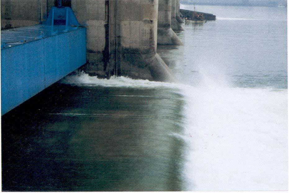
36 6.3 Open Channel Flow Applications 36/60 Bucket roller
37 6.3 Open Channel Flow Applications 37/60 Case : Hydraulic Jump When liquid at high velocity discharges into a zone of lower velocity, a rather abrupt rise (a standing wave) occurs in water surface and is accompanied by violent turbulence, eddying, air entrainment, surface undulation. such as a wave is known as a hydraulic jump induce a large head loss (energy dissipation)
38 6.3 Open Channel Flow Applications 38/60
39 6.3 Open Channel Flow Applications 39/60 Apply impulse-momentum equation to find the relation between the depths for a given flowrate Construct a control volume enclosing the hydraulic jump between Sections and where the streamlines are straight and parallel γ y γ y Fx = F F = = qρ( V V) where q = flowrate per unit width Substitute the continuity relations V q y ; = V q = y
40 6.3 Open Channel Flow Applications 40/60 γ Rearrange (divide by ) Solve for q y q y + = + gy gy y y y 8 8 q V = = + + y gy gy Set Fr = V gy Fr = V gy
41 6.3 Open Channel Flow Applications 4/60 where Fr = Froude number = Inertia Force Gravity Force = V gy Then, we have William Froude (80~879) y y = + + 8Fr Jump Equation (a) Fr = : critical flow y y = + + = 8 y y = No Jump
42 6.3 Open Channel Flow Applications 4/60 (b) (c) Fr > Fr < : super-critical flow y y > y : sub-critical flow y y < y > y hydraulic jump < y physically impossible ( rise of energy line through the jump is impossible) Conclusion: For a hydraulic jump to occur, the upstream conditions must be such that V gy >
43 6.3 Open Channel Flow Applications 43/60 [IP 6.3] p. 99 Water flows in a horizontal open channel. y = 0.6 m q = m s m Find y, and power dissipated in hydraulic jump. [Sol] (i) Continuity q= yv = yv 3.7 V = = 6.7 m s 0.6 V 6.7 Fr = = =.54> hydraulic jump occurs gy 9.8(0.6)
44 6.3 Open Channel Flow Applications 44/60 (ii) Jump Eq. y y = + + 8Fr 0.6 = + + 8(.54) =.88 m V 3.7 = = ms
45 6.3 Open Channel Flow Applications 45/60 (iii) Bernoulli Eq. (Work-Energy Eq.) V V y+ = y + + E g g (6.7) (.97) = E (9.8) (9.8) E = 0.46 m Power = γ Q E = 9,800( 3.7)( 0.46) = 6.7 kw meter of width The hydraulic jump is excellent energy dissipater (used in the spillway).

46 6.3 Open Channel Flow Applications 46/60

47 6.3 Open Channel Flow Applications 47/60
48 6.3 Open Channel Flow Applications 48/60 Case 4: Wave Propagation The velocity (celerity) of small gravity waves in a body of water can be calculated by the impulse-momentum equation. Small gravity waves ~ appears as a small localized rise in the liquid surface which propagate at a velocity a ~ extends over the full depth of the flow [Cf] small surface disturbance (ripple) ~ liquid movement is restricted to a region near the surface

49 6.3 Open Channel Flow Applications 49/60
50 6.3 Open Channel Flow Applications 50/60 For the steady flow, assign the velocity under the wave as a From continuity ( ) ' ay = a y + dy From impulse-momentum ( y + dy) γ y γ = ' ( ay) ρ ( a a) Combining these two equations gives ( ) a = g y + dy Letting dy approach zero results in a = gy The celerity of the samll gravity wave depends only on the depth of flow.
51 6.4 The Angular Impulse-Momentum Principle 5/60 The angular impulse-momentum equation can be developed using moments of the force and momentum vectors Take a moment of forces and momentum vectors for the small individual fluid system about 0 d d r F = ( r mv) ( r d Vol v) dt = dt ρ Sum this for control volume d r Fext = ( r v) ρd Vol. dt sys (6.9) (a)
52 6.4 The Angular Impulse-Momentum Principle 5/60 (x, z ) (x, z )
53 6.4 The Angular Impulse-Momentum Principle 53/60 Use Reynolds Transport Theorem to evaluate the integral de d = ( r v) ρd Vol. iρv da dt dt = sys C. S. ( r v ) v da ( = ρ + r v ) ρv da C. S. out C. S. in (6.0) (b) where E = i= r v moment of momentum of fluid system = moment of momentum per unit mass Restrict to control volume where the fluid enters and leaves at sections where the streamlines are straight and parallel and with the velocity normal to the cross-sectional area d ( r v) d Vol. ( r v) dq ( r v) dq dt ρ = sys ρ ρ C. S. out C. S. in (6.)
54 6.4 The Angular Impulse-Momentum Principle 54/60 Because velocity is uniform over the flow cross sections where d ( r v) ρdvol. = Qρ( rout Vout ) Qρ( rin Vin ) dt sys = Qρ ( r V) out ( r V) in r = (6.) position vector from the moment center to the centroid of entering or leaving flow cross section of the control volume Substitute (c) into (a) (c) ( r F ) = M = Qρ ( r V) ( r V) ext 0 out in (6.3)
55 6.4 The Angular Impulse-Momentum Principle 55/60 In -D flow, M = Qρ( rv rv ) (6.4) 0 t t where V t = component of velocity normal to the moment arm r. In rectangular components, assuming V is directed with positive components in both x and z-direction, and with the moment center at the origin of the x-z coordinate system, for clockwise positive moments, [( ) ( )] M = Qρ zv xv zv xv 0 x z x z (6.5) where x, z = x, z = coordinates of centroid of the entering cross section coordinates of centroid of the leaving cross section
56 6.4 The Angular Impulse-Momentum Principle 56/60 For the fluid that enter or leave the control volume at more than one cross-section, M 0 = ( QρrVt ) out ( QρrVt ) in (6.6) [IP 6.6] p. 06 Water flowing on the pipe bend Compute the location of the resultant force exerted by the water on the pipe bend. Assume that center of gravity of the fluid is 0.55 m to the right of section, and the forces F and F act at the centroid of the sections rather than at the center of pressure. Take moments about the center of section
57 6.4 The Angular Impulse-Momentum Principle 57/60
58 6.4 The Angular Impulse-Momentum Principle 58/60 [( ) ( )] M = Qρ z v xv zv xv For this case, 0 x x x x T = r(8,83) (833) +.5(590cos 60 ) 0.6( 590sin 60 ) = ( ).5( 9.55 cos60 ) 0.6(9.55 sin 60 ) r = 0.59 m [Re] Torque for rotating system d T = ( r F) = ( r mvc) dt
59 6.4 The Angular Impulse-Momentum Principle 59/60 Where r = T = T dt = r mv c = torque torque impulse angular momentum (moment of momentum) radius vector from the origin 0 to the point of application of a force [Re] Vector product (cross product) V = F G -Magnitude: V= FGsinφ -Direction: perpendicular to the plane of F and G (right-hand rule) If F, G are in the plane of x and y, then the V is in the plane. z
60 6.4 The Angular Impulse-Momentum Principle 60/60 Homework Assignment # 6 Due: week from today Prob. 6. Prob. 6.6 Prob. 6.4 Prob. 6.6 Prob Prob Prob Prob Prob Prob. 6.60
Chapter 6 The Impulse-Momentum Principle
 Chapter 6 The Impulse-Momentum Principle 6. The Linear Impulse-Momentum Equation 6. Pipe Flow Applications 6.3 Open Channel Flow Applications 6.4 The Angular Impulse-Momentum Principle Objectives: - Develop
CHAPTER 3 BASIC EQUATIONS IN FLUID MECHANICS NOOR ALIZA AHMAD
 CHAPTER 3 BASIC EQUATIONS IN FLUID MECHANICS 1 INTRODUCTION Flow often referred as an ideal fluid. We presume that such a fluid has no viscosity. However, this is an idealized situation that does not exist.
Chapter 4 Continuity Equation and Reynolds Transport Theorem
 Chapter 4 Continuity Equation and Reynolds Transport Theorem 4.1 Control Volume 4. The Continuity Equation for One-Dimensional Steady Flow 4.3 The Continuity Equation for Two-Dimensional Steady Flow 4.4
Fluid Mechanics. du dy
 FLUID MECHANICS Technical English - I 1 th week Fluid Mechanics FLUID STATICS FLUID DYNAMICS Fluid Statics or Hydrostatics is the study of fluids at rest. The main equation required for this is Newton's
Consider a control volume in the form of a straight section of a streamtube ABCD.
 6 MOMENTUM EQUATION 6.1 Momentum and Fluid Flow In mechanics, the momentum of a particle or object is defined as the product of its mass m and its velocity v: Momentum = mv The particles of a fluid stream
1.060 Engineering Mechanics II Spring Problem Set 4
 1.060 Engineering Mechanics II Spring 2006 Due on Monday, March 20th Problem Set 4 Important note: Please start a new sheet of paper for each problem in the problem set. Write the names of the group members
Lesson 6 Review of fundamentals: Fluid flow
 Lesson 6 Review of fundamentals: Fluid flow The specific objective of this lesson is to conduct a brief review of the fundamentals of fluid flow and present: A general equation for conservation of mass
Chapter 5 Control Volume Approach and Continuity Equation
 Chapter 5 Control Volume Approach and Continuity Equation Lagrangian and Eulerian Approach To evaluate the pressure and velocities at arbitrary locations in a flow field. The flow into a sudden contraction,
COURSE NUMBER: ME 321 Fluid Mechanics I 3 credit hour. Basic Equations in fluid Dynamics
 COURSE NUMBER: ME 321 Fluid Mechanics I 3 credit hour Basic Equations in fluid Dynamics Course teacher Dr. M. Mahbubur Razzaque Professor Department of Mechanical Engineering BUET 1 Description of Fluid
NPTEL Quiz Hydraulics
 Introduction NPTEL Quiz Hydraulics 1. An ideal fluid is a. One which obeys Newton s law of viscosity b. Frictionless and incompressible c. Very viscous d. Frictionless and compressible 2. The unit of kinematic
Chapter 2: Basic Governing Equations
 -1 Reynolds Transport Theorem (RTT) - Continuity Equation -3 The Linear Momentum Equation -4 The First Law of Thermodynamics -5 General Equation in Conservative Form -6 General Equation in Non-Conservative
Chapter 3 Bernoulli Equation
 1 Bernoulli Equation 3.1 Flow Patterns: Streamlines, Pathlines, Streaklines 1) A streamline, is a line that is everywhere tangent to the velocity vector at a given instant. Examples of streamlines around
Sourabh V. Apte. 308 Rogers Hall
 Sourabh V. Apte 308 Rogers Hall sva@engr.orst.edu 1 Topics Quick overview of Fluid properties, units Hydrostatic forces Conservation laws (mass, momentum, energy) Flow through pipes (friction loss, Moody
Basic Fluid Mechanics
 Basic Fluid Mechanics Chapter 6A: Internal Incompressible Viscous Flow 4/16/2018 C6A: Internal Incompressible Viscous Flow 1 6.1 Introduction For the present chapter we will limit our study to incompressible
VARIED FLOW IN OPEN CHANNELS
 Chapter 15 Open Channels vs. Closed Conduits VARIED FLOW IN OPEN CHANNELS Fluid Mechanics, Spring Term 2011 In a closed conduit there can be a pressure gradient that drives the flow. An open channel has
Chapter Four fluid flow mass, energy, Bernoulli and momentum
 4-1Conservation of Mass Principle Consider a control volume of arbitrary shape, as shown in Fig (4-1). Figure (4-1): the differential control volume and differential control volume (Total mass entering
FE Fluids Review March 23, 2012 Steve Burian (Civil & Environmental Engineering)
") Topic: Fluid Properties 1. If 6 m 3 of oil weighs 47 kn, calculate its specific weight, density, and specific gravity. 2. 10.0 L of an incompressible liquid exert a force of 20 N at the earth s surface.
Topic: Fluid Properties 1. If 6 m 3 of oil weighs 47 kn, calculate its specific weight, density, and specific gravity. 2. 10.0 L of an incompressible liquid exert a force of 20 N at the earth s surface.
FLUID MECHANICS. Chapter 3 Elementary Fluid Dynamics - The Bernoulli Equation
 FLUID MECHANICS Chapter 3 Elementary Fluid Dynamics - The Bernoulli Equation CHAP 3. ELEMENTARY FLUID DYNAMICS - THE BERNOULLI EQUATION CONTENTS 3. Newton s Second Law 3. F = ma along a Streamline 3.3
Lesson 37 Transmission Of Air In Air Conditioning Ducts
 Lesson 37 Transmission Of Air In Air Conditioning Ducts Version 1 ME, IIT Kharagpur 1 The specific objectives of this chapter are to: 1. Describe an Air Handling Unit (AHU) and its functions (Section 37.1).
vector H. If O is the point about which moments are desired, the angular moment about O is given:
 The angular momentum A control volume analysis can be applied to the angular momentum, by letting B equal to angularmomentum vector H. If O is the point about which moments are desired, the angular moment
The Bernoulli Equation
 The Bernoulli Equation The most used and the most abused equation in fluid mechanics. Newton s Second Law: F = ma In general, most real flows are 3-D, unsteady (x, y, z, t; r,θ, z, t; etc) Let consider
FE Exam Fluids Review October 23, Important Concepts
 FE Exam Fluids Review October 3, 013 mportant Concepts Density, specific volume, specific weight, specific gravity (Water 1000 kg/m^3, Air 1. kg/m^3) Meaning & Symbols? Stress, Pressure, Viscosity; Meaning
Chapter 6: Momentum Analysis
 6-1 Introduction 6-2Newton s Law and Conservation of Momentum 6-3 Choosing a Control Volume 6-4 Forces Acting on a Control Volume 6-5Linear Momentum Equation 6-6 Angular Momentum 6-7 The Second Law of
Hydraulics for Urban Storm Drainage
 Urban Hydraulics Hydraulics for Urban Storm Drainage Learning objectives: understanding of basic concepts of fluid flow and how to analyze conduit flows, free surface flows. to analyze, hydrostatic pressure
Closed duct flows are full of fluid, have no free surface within, and are driven by a pressure gradient along the duct axis.
 OPEN CHANNEL FLOW Open channel flow is a flow of liquid, basically water in a conduit with a free surface. The open channel flows are driven by gravity alone, and the pressure gradient at the atmospheric
PROPERTIES OF FLUIDS
 Unit - I Chapter - PROPERTIES OF FLUIDS Solutions of Examples for Practice Example.9 : Given data : u = y y, = 8 Poise = 0.8 Pa-s To find : Shear stress. Step - : Calculate the shear stress at various
10.52 Mechanics of Fluids Spring 2006 Problem Set 3
 10.52 Mechanics of Fluids Spring 2006 Problem Set 3 Problem 1 Mass transfer studies involving the transport of a solute from a gas to a liquid often involve the use of a laminar jet of liquid. The situation
In this section, mathematical description of the motion of fluid elements moving in a flow field is
 Jun. 05, 015 Chapter 6. Differential Analysis of Fluid Flow 6.1 Fluid Element Kinematics In this section, mathematical description of the motion of fluid elements moving in a flow field is given. A small
Lecture 4. Differential Analysis of Fluid Flow Navier-Stockes equation
 Lecture 4 Differential Analysis of Fluid Flow Navier-Stockes equation Newton second law and conservation of momentum & momentum-of-momentum A jet of fluid deflected by an object puts a force on the object.
Closed duct flows are full of fluid, have no free surface within, and are driven by a pressure gradient along the duct axis.
 OPEN CHANNEL FLOW Open channel flow is a flow of liquid, basically water in a conduit with a free surface. The open channel flows are driven by gravity alone, and the pressure gradient at the atmospheric
Control Volume Revisited
 Civil Engineering Hydraulics Control Volume Revisited Previously, we considered developing a control volume so that we could isolate mass flowing into and out of the control volume Our goal in developing
Q1 Give answers to all of the following questions (5 marks each):
:") FLUID MECHANICS First Year Exam Solutions 03 Q Give answers to all of the following questions (5 marks each): (a) A cylinder of m in diameter is made with material of relative density 0.5. It is moored
FLUID MECHANICS First Year Exam Solutions 03 Q Give answers to all of the following questions (5 marks each): (a) A cylinder of m in diameter is made with material of relative density 0.5. It is moored
2 Internal Fluid Flow
 Internal Fluid Flow.1 Definitions Fluid Dynamics The study of fluids in motion. Static Pressure The pressure at a given point exerted by the static head of the fluid present directly above that point.
Shell Balances in Fluid Mechanics
 Shell Balances in Fluid Mechanics R. Shankar Subramanian Department of Chemical and Biomolecular Engineering Clarkson University When fluid flow occurs in a single direction everywhere in a system, shell
ROAD MAP... D-0: Reynolds Transport Theorem D-1: Conservation of Mass D-2: Conservation of Momentum D-3: Conservation of Energy
 ES06 Fluid Mechani UNIT D: Flow Field Analysis ROAD MAP... D-0: Reynolds Transport Theorem D-1: Conservation of Mass D-: Conservation of Momentum D-3: Conservation of Energy ES06 Fluid Mechani Unit D-0:
ENERGY TRANSFER BETWEEN FLUID AND ROTOR. Dr. Ir. Harinaldi, M.Eng Mechanical Engineering Department Faculty of Engineering University of Indonesia
 ENERGY TRANSFER BETWEEN FLUID AND ROTOR Dr. Ir. Harinaldi, M.Eng Mechanical Engineering Department Faculty of Engineering University of Indonesia Basic Laws and Equations Continuity Equation m m ρ mass
FLUID MECHANICS PROF. DR. METİN GÜNER COMPILER
 FLUID MECHANICS PROF. DR. METİN GÜNER COMPILER ANKARA UNIVERSITY FACULTY OF AGRICULTURE DEPARTMENT OF AGRICULTURAL MACHINERY AND TECHNOLOGIES ENGINEERING 1 5. FLOW IN PIPES 5.1.3. Pressure and Shear Stress
R09. d water surface. Prove that the depth of pressure is equal to p +.
 Code No:A109210105 R09 SET-1 B.Tech II Year - I Semester Examinations, December 2011 FLUID MECHANICS (CIVIL ENGINEERING) Time: 3 hours Max. Marks: 75 Answer any five questions All questions carry equal
HOMEWORK ASSIGNMENT ON BERNOULLI S EQUATION
 AMEE 0 Introduction to Fluid Mechanics Instructor: Marios M. Fyrillas Email: m.fyrillas@frederick.ac.cy HOMEWORK ASSIGNMENT ON BERNOULLI S EQUATION. Conventional spray-guns operate by achieving a low pressure
CHAPTER 4 The Integral Forms of the Fundamental Laws
 CHAPTER 4 The Integral Forms of the Fundamental Laws FE-type Exam Review Problems: Problems 4- to 4-5 4 (B) 4 (D) 4 (A) 44 (D) p m ρa A π 4 7 87 kg/s RT 87 9 Refer to the circle of Problem 47: 757 Q A
5 ENERGY EQUATION OF FLUID MOTION
 5 ENERGY EQUATION OF FLUID MOTION 5.1 Introduction In order to develop the equations that describe a flow, it is assumed that fluids are subject to certain fundamental laws of physics. The pertinent laws
Fluid Mechanics Prof. S.K. Som Department of Mechanical Engineering Indian Institute of Technology, Kharagpur
 Fluid Mechanics Prof. S.K. Som Department of Mechanical Engineering Indian Institute of Technology, Kharagpur Lecture - 42 Flows with a Free Surface Part II Good morning. I welcome you to this session
Experiment (4): Flow measurement
: Flow measurement") Experiment (4): Flow measurement Introduction: The flow measuring apparatus is used to familiarize the students with typical methods of flow measurement of an incompressible fluid and, at the same time
Experiment (4): Flow measurement Introduction: The flow measuring apparatus is used to familiarize the students with typical methods of flow measurement of an incompressible fluid and, at the same time
BERNOULLI EQUATION. The motion of a fluid is usually extremely complex.
 BERNOULLI EQUATION The motion of a fluid is usually extremely complex. The study of a fluid at rest, or in relative equilibrium, was simplified by the absence of shear stress, but when a fluid flows over
2.The lines that are tangent to the velocity vectors throughout the flow field are called steady flow lines. True or False A. True B.
 CHAPTER 03 1. Write Newton's second law of motion. YOUR ANSWER: F = ma 2.The lines that are tangent to the velocity vectors throughout the flow field are called steady flow lines. True or False 3.Streamwise
Chapter (3) Water Flow in Pipes
 Water Flow in Pipes") Chapter (3) Water Flow in Pipes Water Flow in Pipes Bernoulli Equation Recall fluid mechanics course, the Bernoulli equation is: P 1 ρg + v 1 g + z 1 = P ρg + v g + z h P + h T + h L Here, we want to study
Chapter (3) Water Flow in Pipes Water Flow in Pipes Bernoulli Equation Recall fluid mechanics course, the Bernoulli equation is: P 1 ρg + v 1 g + z 1 = P ρg + v g + z h P + h T + h L Here, we want to study
s and FE X. A. Flow measurement B. properties C. statics D. impulse, and momentum equations E. Pipe and other internal flow 7% of FE Morning Session I
 Fundamentals of Engineering (FE) Exam General Section Steven Burian Civil & Environmental Engineering October 26, 2010 s and FE X. A. Flow measurement B. properties C. statics D. impulse, and momentum
Pressure in stationary and moving fluid Lab- Lab On- On Chip: Lecture 2
 Pressure in stationary and moving fluid Lab-On-Chip: Lecture Lecture plan what is pressure e and how it s distributed in static fluid water pressure in engineering problems buoyancy y and archimedes law;
Answers to questions in each section should be tied together and handed in separately.
 EGT0 ENGINEERING TRIPOS PART IA Wednesday 4 June 014 9 to 1 Paper 1 MECHANICAL ENGINEERING Answer all questions. The approximate number of marks allocated to each part of a question is indicated in the
Therefore, the control volume in this case can be treated as a solid body, with a net force or thrust of. bm # V
 When the mass m of the control volume remains nearly constant, the first term of the Eq. 6 8 simply becomes mass times acceleration since 39 CHAPTER 6 d(mv ) CV m dv CV CV (ma ) CV Therefore, the control
P10.5 Water flows down a rectangular channel that is 4 ft wide and 3 ft deep. The flow rate is 15,000 gal/min. Estimate the Froude number of the flow.
 P10.5 Water flows down a rectangular channel that is 4 ft wide and ft deep. The flow rate is 15,000 gal/min. Estimate the Froude number of the flow. Solution: Convert the flow rate from 15,000 gal/min
Experiment- To determine the coefficient of impact for vanes. Experiment To determine the coefficient of discharge of an orifice meter.
 SUBJECT: FLUID MECHANICS VIVA QUESTIONS (M.E 4 th SEM) Experiment- To determine the coefficient of impact for vanes. Q1. Explain impulse momentum principal. Ans1. Momentum equation is based on Newton s
CIE4491 Lecture. Hydraulic design
 CIE4491 Lecture. Hydraulic design Marie-claire ten Veldhuis 19-9-013 Delft University of Technology Challenge the future Hydraulic design of urban stormwater systems Focus on sewer pipes Pressurized and
6.1 Momentum Equation for Frictionless Flow: Euler s Equation The equations of motion for frictionless flow, called Euler s
 Chapter 6 INCOMPRESSIBLE INVISCID FLOW All real fluids possess viscosity. However in many flow cases it is reasonable to neglect the effects of viscosity. It is useful to investigate the dynamics of an
Where does Bernoulli's Equation come from?
 Where does Bernoulli's Equation come from? Introduction By now, you have seen the following equation many times, using it to solve simple fluid problems. P ρ + v + gz = constant (along a streamline) This
Mass of fluid leaving per unit time
 5 ENERGY EQUATION OF FLUID MOTION 5.1 Eulerian Approach & Control Volume In order to develop the equations that describe a flow, it is assumed that fluids are subject to certain fundamental laws of physics.
Chapter (6) Energy Equation and Its Applications
 Energy Equation and Its Applications") Chapter (6) Energy Equation and Its Applications Bernoulli Equation Bernoulli equation is one of the most useful equations in fluid mechanics and hydraulics. And it s a statement of the principle of conservation
Chapter (6) Energy Equation and Its Applications Bernoulli Equation Bernoulli equation is one of the most useful equations in fluid mechanics and hydraulics. And it s a statement of the principle of conservation
Fluids. Fluids in Motion or Fluid Dynamics
 Fluids Fluids in Motion or Fluid Dynamics Resources: Serway - Chapter 9: 9.7-9.8 Physics B Lesson 3: Fluid Flow Continuity Physics B Lesson 4: Bernoulli's Equation MIT - 8: Hydrostatics, Archimedes' Principle,
Bernoulli s equation may be developed as a special form of the momentum or energy equation.
 BERNOULLI S EQUATION Bernoulli equation may be developed a a pecial form of the momentum or energy equation. Here, we will develop it a pecial cae of momentum equation. Conider a teady incompreible flow
3.8 The First Law of Thermodynamics and the Energy Equation
 CEE 3310 Control Volume Analysis, Sep 30, 2011 65 Review Conservation of angular momentum 1-D form ( r F )ext = [ˆ ] ( r v)d + ( r v) out ṁ out ( r v) in ṁ in t CV 3.8 The First Law of Thermodynamics and
Hydraulics. B.E. (Civil), Year/Part: II/II. Tutorial solutions: Pipe flow. Tutorial 1
, Year/Part: II/II. Tutorial solutions: Pipe flow. Tutorial 1") Hydraulics B.E. (Civil), Year/Part: II/II Tutorial solutions: Pipe flow Tutorial 1 -by Dr. K.N. Dulal Laminar flow 1. A pipe 200mm in diameter and 20km long conveys oil of density 900 kg/m 3 and viscosity
Hydraulics B.E. (Civil), Year/Part: II/II Tutorial solutions: Pipe flow Tutorial 1 -by Dr. K.N. Dulal Laminar flow 1. A pipe 200mm in diameter and 20km long conveys oil of density 900 kg/m 3 and viscosity
CEE 3310 Open Channel Flow, Nov. 26,
 CEE 3310 Open Channel Flow, Nov. 6, 018 175 8.10 Review Open Channel Flow Gravity friction balance. y Uniform Flow x = 0 z = S 0L = h f y Rapidly Varied Flow x 1 y Gradually Varied Flow x 1 In general
NPTEL Course Developer for Fluid Mechanics DYMAMICS OF FLUID FLOW
 Module 04; Lecture DYMAMICS OF FLUID FLOW Energy Equation (Conservation of Energy) In words, the conservation of energy can be stated as, Time rate of increase in stored energy of the system = Net time
V/ t = 0 p/ t = 0 ρ/ t = 0. V/ s = 0 p/ s = 0 ρ/ s = 0
 UNIT III FLOW THROUGH PIPES 1. List the types of fluid flow. Steady and unsteady flow Uniform and non-uniform flow Laminar and Turbulent flow Compressible and incompressible flow Rotational and ir-rotational
Visualization of flow pattern over or around immersed objects in open channel flow.
 EXPERIMENT SEVEN: FLOW VISUALIZATION AND ANALYSIS I OBJECTIVE OF THE EXPERIMENT: Visualization of flow pattern over or around immersed objects in open channel flow. II THEORY AND EQUATION: Open channel:
Mechanical Engineering Programme of Study
 Mechanical Engineering Programme of Study Fluid Mechanics Instructor: Marios M. Fyrillas Email: eng.fm@fit.ac.cy SOLVED EXAMPLES ON VISCOUS FLOW 1. Consider steady, laminar flow between two fixed parallel
Conservation of Angular Momentum
 10 March 2017 Conservation of ngular Momentum Lecture 23 In the last class, we discussed about the conservation of angular momentum principle. Using RTT, the angular momentum principle was given as DHo
Fluid Mechanics Answer Key of Objective & Conventional Questions
 019 MPROVEMENT Mechanical Engineering Fluid Mechanics Answer Key of Objective & Conventional Questions 1 Fluid Properties 1. (c). (b) 3. (c) 4. (576) 5. (3.61)(3.50 to 3.75) 6. (0.058)(0.05 to 0.06) 7.
Chapter 1 INTRODUCTION
 Chapter 1 INTRODUCTION 1-1 The Fluid. 1-2 Dimensions. 1-3 Units. 1-4 Fluid Properties. 1 1-1 The Fluid: It is the substance that deforms continuously when subjected to a shear stress. Matter Solid Fluid
Chapter 6: Momentum Analysis of Flow Systems
 Chapter 6: Momentum Analysis of Flow Systems Introduction Fluid flow problems can be analyzed using one of three basic approaches: differential, experimental, and integral (or control volume). In Chap.
MOMENTUM PRINCIPLE. Review: Last time, we derived the Reynolds Transport Theorem: Chapter 6. where B is any extensive property (proportional to mass),
,") Chapter 6 MOMENTUM PRINCIPLE Review: Last time, we derived the Reynolds Transport Theorem: where B is any extensive property (proportional to mass), and b is the corresponding intensive property (B / m
Chapter 6 MOMENTUM PRINCIPLE Review: Last time, we derived the Reynolds Transport Theorem: where B is any extensive property (proportional to mass), and b is the corresponding intensive property (B / m
Benha University College of Engineering at Benha Questions For Corrective Final Examination Subject: Fluid Mechanics M 201 May 24/ 2016
 Benha University College of Engineering at Benha Questions For Corrective Final Examination Subject: Fluid Mechanics M 01 May 4/ 016 Second year Mech. Time :180 min. Examiner:Dr.Mohamed Elsharnoby Attempt
11.1 Mass Density. Fluids are materials that can flow, and they include both gases and liquids. The mass density of a liquid or gas is an
 Chapter 11 Fluids 11.1 Mass Density Fluids are materials that can flow, and they include both gases and liquids. The mass density of a liquid or gas is an important factor that determines its behavior
Chapter 4: Non uniform flow in open channels
 Chapter 4: Non uniform flow in open channels Learning outcomes By the end of this lesson, students should be able to: Relate the concept of specific energy and momentum equations in the effect of change
Angular momentum equation
 Angular momentum equation For angular momentum equation, B =H O the angular momentum vector about point O which moments are desired. Where β is The Reynolds transport equation can be written as follows:
 CE 6303 MECHANICS OF FLUIDS L T P C QUESTION BANK 3 0 0 3 UNIT I FLUID PROPERTIES AND FLUID STATICS PART - A 1. Define fluid and fluid mechanics. 2. Define real and ideal fluids. 3. Define mass density
CEE 3310 Control Volume Analysis, Oct. 10, = dt. sys
 CEE 3310 Control Volume Analysis, Oct. 10, 2018 77 3.16 Review First Law of Thermodynamics ( ) de = dt Q Ẇ sys Sign convention: Work done by the surroundings on the system < 0, example, a pump! Work done
57:020 Mechanics of Fluids and Transfer Processes CONSERVATION OF MASS, LINEAR MOMENTUM, AND ENERGY IN A SLUICE GATE FLOW. dt dt. d ( momentum.
 57: Mechani of Fluids and Transfer Processes CONSERVATION OF MASS, LINEAR MOMENTUM, AND ENERGY IN A SLUICE GATE FLOW Purpose To measure the total piezometric pressure at various locations along a vertical
Friction Factors and Drag Coefficients
 Levicky 1 Friction Factors and Drag Coefficients Several equations that we have seen have included terms to represent dissipation of energy due to the viscous nature of fluid flow. For example, in the
Exam #2: Fluid Kinematics and Conservation Laws April 13, 2016, 7:00 p.m. 8:40 p.m. in CE 118
 CVEN 311-501 (Socolofsky) Fluid Dynamics Exam #2: Fluid Kinematics and Conservation Laws April 13, 2016, 7:00 p.m. 8:40 p.m. in CE 118 Name: : UIN: : Instructions: Fill in your name and UIN in the space
Hydraulics Part: Open Channel Flow
 Hydraulics Part: Open Channel Flow Tutorial solutions -by Dr. K.N. Dulal Uniform flow 1. Show that discharge through a channel with steady flow is given by where A 1 and A 2 are the sectional areas of
The most common methods to identify velocity of flow are pathlines, streaklines and streamlines.
 4 FLUID FLOW 4.1 Introduction Many civil engineering problems in fluid mechanics are concerned with fluids in motion. The distribution of potable water, the collection of domestic sewage and storm water,
EXPERIMENT No.1 FLOW MEASUREMENT BY ORIFICEMETER
 EXPERIMENT No.1 FLOW MEASUREMENT BY ORIFICEMETER 1.1 AIM: To determine the co-efficient of discharge of the orifice meter 1.2 EQUIPMENTS REQUIRED: Orifice meter test rig, Stopwatch 1.3 PREPARATION 1.3.1
Aerodynamics. Basic Aerodynamics. Continuity equation (mass conserved) Some thermodynamics. Energy equation (energy conserved)
 Some thermodynamics. Energy equation (energy conserved)") Flow with no friction (inviscid) Aerodynamics Basic Aerodynamics Continuity equation (mass conserved) Flow with friction (viscous) Momentum equation (F = ma) 1. Euler s equation 2. Bernoulli s equation
Flow with no friction (inviscid) Aerodynamics Basic Aerodynamics Continuity equation (mass conserved) Flow with friction (viscous) Momentum equation (F = ma) 1. Euler s equation 2. Bernoulli s equation
Lecture 3 The energy equation
 Lecture 3 The energy equation Dr Tim Gough: t.gough@bradford.ac.uk General information Lab groups now assigned Timetable up to week 6 published Is there anyone not yet on the list? Week 3 Week 4 Week 5
UNIT IV DIMENSIONAL AND MODEL ANALYSIS
 UNIT IV DIMENSIONAL AND MODEL ANALYSIS INTRODUCTION Dimensional analysis is a method of dimensions. It is a mathematical technique used in research work for design and for conducting model tests. It deals
28.2 Classification of Jumps
 28.2 Classification of Jumps As mentioned earlier, the supercritical flow Froude number influences the characteristics of the hydraulic jump. Bradley and Peterka, after extensive experimental investigations,
!! +! 2!! +!"!! =!! +! 2!! +!"!! +!!"!"!"
 Homework 4 Solutions 1. (15 points) Bernoulli s equation can be adapted for use in evaluating unsteady flow conditions, such as those encountered during start- up processes. For example, consider the large
INSTITUTE OF AERONAUTICAL ENGINEERING Dundigal, Hyderabad AERONAUTICAL ENGINEERING QUESTION BANK : AERONAUTICAL ENGINEERING.
 Course Name Course Code Class Branch INSTITUTE OF AERONAUTICAL ENGINEERING Dundigal, Hyderabad - 00 0 AERONAUTICAL ENGINEERING : Mechanics of Fluids : A00 : II-I- B. Tech Year : 0 0 Course Coordinator
SYSTEMS VS. CONTROL VOLUMES. Control volume CV (open system): Arbitrary geometric space, surrounded by control surfaces (CS)
: Arbitrary geometric space, surrounded by control surfaces (CS)") SYSTEMS VS. CONTROL VOLUMES System (closed system): Predefined mass m, surrounded by a system boundary Control volume CV (open system): Arbitrary geometric space, surrounded by control surfaces (CS) Many
SYSTEMS VS. CONTROL VOLUMES System (closed system): Predefined mass m, surrounded by a system boundary Control volume CV (open system): Arbitrary geometric space, surrounded by control surfaces (CS) Many
Fluid Dynamics Exercises and questions for the course
 Fluid Dynamics Exercises and questions for the course January 15, 2014 A two dimensional flow field characterised by the following velocity components in polar coordinates is called a free vortex: u r
OPEN CHANNEL FLOW. One-dimensional - neglect vertical and lateral variations in velocity. In other words, Q v = (1) A. Figure 1. One-dimensional Flow
 A. Figure 1. One-dimensional Flow") OPEN CHANNEL FLOW Page 1 OPEN CHANNEL FLOW Open Channel Flow (OCF) is flow with one boundary exposed to atmospheric pressure. The flow is not pressurized and occurs because of gravity. Flow Classification
OPEN CHANNEL FLOW Page 1 OPEN CHANNEL FLOW Open Channel Flow (OCF) is flow with one boundary exposed to atmospheric pressure. The flow is not pressurized and occurs because of gravity. Flow Classification
Answers to test yourself questions
 Answers to test yourself questions Option B B Rotational dynamics ( ω + ω )t Use 0 ( +.).0 θ to get θ 46. 46 rad. Use ω ω0 + αθ to get ω.0 +. 4 and so ω 7.8 7 rad s. Use ω ω0 + αθ to get.4. + α 0 π. Hence
1.060 Engineering Mechanics II Spring Problem Set 8
 1.060 Engineering Mechanics II Spring 2006 Due on Monday, May 1st Problem Set 8 Important note: Please start a new sheet of paper for each problem in the problem set. Write the names of the group members
2 Navier-Stokes Equations
 1 Integral analysis 1. Water enters a pipe bend horizontally with a uniform velocity, u 1 = 5 m/s. The pipe is bended at 90 so that the water leaves it vertically downwards. The input diameter d 1 = 0.1
conservation of linear momentum 1+8Fr = 1+ Sufficiently short that energy loss due to channel friction is negligible h L = 0 Bernoulli s equation.
 174 Review Flow through a contraction Critical and choked flows The hydraulic jump conservation of linear momentum y y 1 = 1+ 1+8Fr 1 8.1 Rapidly Varied Flows Weirs 8.1.1 Broad-Crested Weir Consider the
MULTIPLE-CHOICE PROBLEMS:(Two marks per answer) (Circle the Letter Beside the Most Correct Answer in the Questions Below.)
 (Circle the Letter Beside the Most Correct Answer in the Questions Below.)") MULTIPLE-CHOICE PROLEMS:(Two marks per answer) (Circle the Letter eside the Most Correct Answer in the Questions elow.) 1. The absolute viscosity µ of a fluid is primarily a function of: a. Density. b.
MULTIPLE-CHOICE PROLEMS:(Two marks per answer) (Circle the Letter eside the Most Correct Answer in the Questions elow.) 1. The absolute viscosity µ of a fluid is primarily a function of: a. Density. b.
CVE 372 HYDROMECHANICS EXERCISE PROBLEMS
 VE 37 HYDROMEHNIS EXERISE PROLEMS 1. pump that has the characteristic curve shown in the accompanying graph is to be installed in the system shown. What will be the discharge of water in the system? Take
EFFECT OF BAFFLE BLOCKS ON THE PERFORMANCE OF RADIAL HYDRAULIC JUMP
 Fourth International Water Technology Conference IWTC 99, Alexandria, Egypt 255 EFFECT OF BAFFLE BLOCKS ON THE PERFORMANCE OF RADIAL HYDRAULIC JUMP O. S. Rageh Irrigation & Hydraulics Dept., Faculty of
Chapter Two. Basic Thermodynamics, Fluid Mechanics: Definitions of Efficiency. Laith Batarseh
 Chapter Two Basic Thermodynamics, Fluid Mechanics: Definitions of Efficiency Laith Batarseh The equation of continuity Most analyses in this book are limited to one-dimensional steady flows where the velocity