Basic Fluid Mechanics
|
|
|
- Jordan Trevor Lawrence
- 5 years ago
- Views:
Transcription


1 Basic Fluid Mechanics Chapter 6A: Internal Incompressible Viscous Flow 4/16/2018 C6A: Internal Incompressible Viscous Flow Introduction For the present chapter we will limit our study to incompressible flows. (i.e., M=0.3 which for air at standard conditions corresponds to a speed of approximately 100m/s). Internal flows can be classified as either laminar, transitional or turbulent. The particular flow regime is primarily dependent on the Reynolds number, surface roughness, and level of initial disturbances present within the flow. The Reynolds number is defined as; ρ μ 4/16/2018 C6A: Internal Incompressible Viscous Flow 2 1


2 6.1 Introduction Under normal conditions transition from a laminar to turbulent flow occurs at a critical Re ~ 2,000 in a circular tube or pipe. However, minimizing the disturbances within the flow has, for a smooth circular tube, remained laminar up to Re ~ 100,000. Note: Turbulent flows have random fluctuating velocities which result a in violent mixing action. 4/16/2018 C6A: Internal Incompressible Viscous Flow Introduction Recall for a laminar flow the shear stress is: τ = μ du/dy Shear stress in turbulent flow is written as: 4/16/2018 C6A: Internal Incompressible Viscous Flow 4 2


3 6.1 Introduction u z ú z U z average u r ú r U r average p P Time p average 4/16/2018 C6A: Internal Incompressible Viscous Flow Introduction Laminar flow: τ = μ du/dy Turbulent flow: 4/16/2018 C6A: Internal Incompressible Viscous Flow 6 3


4 6.1 Introduction Note: To account for any non-uniformity in the velocity profile a kinetic energy coefficient, is defined; where represents the average cross sectional velocity. For fully developed laminar flows the velocity profile is parabolic and the kinetic energy coefficient = 2. However, for most internal turbulent flows the velocity profile is much more uniform and 1.05, so for convenience unity is typically used. 4/16/2018 C6A: Internal Incompressible Viscous Flow Fully Developed Laminar Flow Consider a steady laminar flow of a viscous fluid inside a circular tube. 4/16/2018 C6A: Internal Incompressible Viscous Flow 8 4

 and no longer changes with downstream distance.")
, is referred to as the hydrodynamic entrance length, L e.")
5 6.2.1 Fully Developed Laminar Flow Let the fluid enter the tube with a uniform velocity. As the fluid moves along the tube a shear layer forms. This layer of low speed fluid grows on the tube wall as a result of viscous effects, i.e., the no-slip condition. As the viscous fluid moves down the tube a shear layer on the tube wall continues to grow and meet at the tube centerline. 4/16/2018 C6A: Internal Incompressible Viscous Flow Fully Developed Laminar Flow Pipe Entrance v At this location the velocity profile becomes developed (i.e., self-similar) and no longer changes with downstream distance. In this self-similar state the velocity profile is said to be Fully Developed. The distance between the tube inlet and location where the velocity profile becomes invariant (i.e., fully developed), is referred to as the hydrodynamic entrance length, L e. In many engineering applications the flow is turbulent and the Re is between 10 4 and 10 5, typically producing an Le/D ~ 25. 4/16/2018 C6A: Internal Incompressible Viscous Flow 10 v v 5
 assumption implies that the hydrodynamic state of the fluid remains")

 follows: So if the flow")
 (6.")

6 6.2.2 Analysis of Flow in a Circular Tube Use of the fully developed flow (FDF) assumption implies that the hydrodynamic state of the fluid remains constant along the length of the tube and that the radial velocity, v r = 0 and / x = 0. For a time independent (i.e., steady) axisymmetric flow in a circular tube the reduced form of the x-momentum eq (in cylindrical coordinates) follows: So if the flow is assumed to be FDF, and since p was shown to vary linearly with x, implying p/ x, we obtain; (6.1) (6.2) 4/16/2018 C6A: Internal Incompressible Viscous Flow a Determine the Velocity Profile Integrate Eq 6.2 w.r.t. r and apply the following boundary conditions; So; Applying boundary condition b one obtains (6.3) 4/16/2018 C6A: Internal Incompressible Viscous Flow 12 6


 It can be quickly observed that the velocity")

7 6.2.2a Determine the Velocity Profile Integrating Eq 6.3, Applying boundary condition a, 4/16/2018 C6A: Internal Incompressible Viscous Flow a Determine the Velocity Profile The resulting velocity profile, (6.4a) It can be quickly observed that the velocity profile is parabolic, and the maximum velocity occurs at the centerline, r = 0. (6.4b) 4/16/2018 C6A: Internal Incompressible Viscous Flow 14 7


 in terms of the mean velocity, (6.")
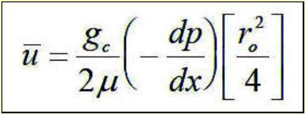
8 6.2.2b Average Streamwise Velocity, where the cross sectional area of the tube, A x = r 2 and da=2 rdr 4/16/2018 C6A: Internal Incompressible Viscous Flow b Average Streamwise Velocity, Rewriting (6.4b) in terms of the mean velocity, (6.4c) 4/16/2018 C6A: Internal Incompressible Viscous Flow 16 8
 4/16/20")

9 6.2.2c Volume Flow Rate Computation (6.5) 4/16/2018 C6A: Internal Incompressible Viscous Flow d Pressure Drop Determination Approximate the pressure gradient and solve for P in Eq 6.5, Multiply and divide right hand side by 4/16/2018 C6A: Internal Incompressible Viscous Flow 18 9

 Note: Shear stress is maximum at the wall of the tube and linearly decreases to zero at the tube")
10 6.2.2d Pressure Drop Determination (6.6) 4/16/2018 C6A: Internal Incompressible Viscous Flow e Evaluation of Shear Stress The x- component of shear stress acting at the tube wall, the only component to survive in the present example is rx since V r = 0 (6.7) Note: Shear stress is maximum at the wall of the tube and linearly decreases to zero at the tube centerline. 4/16/2018 C6A: Internal Incompressible Viscous Flow 20 10
 4/16/2018 C6A: Internal Incompressible Viscous Flow 21 6.")


11 6.2.2e Evaluation of Shear Stress Since the pressure gradient is approximated by p/l then or in terms of the mean velocity (6.8) 4/16/2018 C6A: Internal Incompressible Viscous Flow Friction Factor (f ) The shear stress can be presented in nondimensional terms by normalizing it by the dynamic pressure; where f is the Fanning friction factor. (6.9) Note: 1- There is a second quantity known as the Darcy friction factor, f D that is often used. 2- The two friction factors are related by; f D 4f For the present example, start with eq 6.9 4/16/2018 C6A: Internal Incompressible Viscous Flow 22 11
 is used. 6.")

12 6.3 Friction Factor (f ) (6.10) Typically the mean velocity is defined as shown, where A represents the cross sectional area. 4/16/2018 C6A: Internal Incompressible Viscous Flow 23 In many cases involving internal flow a characteristic length, referred to as the Hydraulic Diameter (Dh) is used. 6.3 Friction Factor (f ) The Hydraulic Diameter (Dh) is defined as, (6.11) For a circular tube, Note: 1 - The above relation for f was determined assuming a laminar flow. 2 - A laminar flow can exist if the Re is below a critical value. 3 - The typical value is quoted as, Re crit = 2000, beyond which the flow undergoes transition and becomes turbulent. 4/16/2018 C6A: Internal Incompressible Viscous Flow 24 12


13 6.3.1 Turbulent Flow Friction Factor (f ) As the flowrate is increased and the Re crit is exceeded the streamlines are no longer straight and become unsteady as the flow transitions from a laminar state. Re UD inertia Viscous forces The primary attribute of turbulence is it variations or fluctuations in both space and time. u z u r p ú z Time U zavg ú r Time U r avg P Time p avg 4/16/2018 C6A: Internal Incompressible Viscous Flow Turbulent Flow Friction Factor (f ) The Moody Diagram Transitional Flow f =16/Re Note: Surface roughness also has an affects the f. 4/16/2018 C6A: Internal Incompressible Viscous Flow 26 13
FLUID MECHANICS PROF. DR. METİN GÜNER COMPILER
 FLUID MECHANICS PROF. DR. METİN GÜNER COMPILER ANKARA UNIVERSITY FACULTY OF AGRICULTURE DEPARTMENT OF AGRICULTURAL MACHINERY AND TECHNOLOGIES ENGINEERING 1 5. FLOW IN PIPES 5.1.3. Pressure and Shear Stress
Chapter 8: Flow in Pipes
 8-1 Introduction 8-2 Laminar and Turbulent Flows 8-3 The Entrance Region 8-4 Laminar Flow in Pipes 8-5 Turbulent Flow in Pipes 8-6 Fully Developed Pipe Flow 8-7 Minor Losses 8-8 Piping Networks and Pump
Chapter 8: Flow in Pipes
 Objectives 1. Have a deeper understanding of laminar and turbulent flow in pipes and the analysis of fully developed flow 2. Calculate the major and minor losses associated with pipe flow in piping networks
Chapter 10 Flow in Conduits
 Chapter 10 Flow in Conduits 10.1 Classifying Flow Laminar Flow and Turbulent Flow Laminar flow Unpredictable Turbulent flow Near entrance: undeveloped developing flow In developing flow, the wall shear
Shell Balances in Fluid Mechanics
 Shell Balances in Fluid Mechanics R. Shankar Subramanian Department of Chemical and Biomolecular Engineering Clarkson University When fluid flow occurs in a single direction everywhere in a system, shell
Principles of Convection
 Principles of Convection Point Conduction & convection are similar both require the presence of a material medium. But convection requires the presence of fluid motion. Heat transfer through the: Solid
Internal Forced Convection. Copyright The McGraw-Hill Companies, Inc. Permission required for reproduction or display.
 Internal Forced Convection Copyright The McGraw-Hill Companies, Inc. Permission required for reproduction or display. Introduction Pipe circular cross section. Duct noncircular cross section. Tubes small-diameter
CONVECTIVE HEAT TRANSFER
 CONVECTIVE HEAT TRANSFER Mohammad Goharkhah Department of Mechanical Engineering, Sahand Unversity of Technology, Tabriz, Iran CHAPTER 4 HEAT TRANSFER IN CHANNEL FLOW BASIC CONCEPTS BASIC CONCEPTS Laminar
6. Basic basic equations I ( )
") 6. Basic basic equations I (4.2-4.4) Steady and uniform flows, streamline, streamtube One-, two-, and three-dimensional flow Laminar and turbulent flow Reynolds number System and control volume Continuity
6. Basic basic equations I (4.2-4.4) Steady and uniform flows, streamline, streamtube One-, two-, and three-dimensional flow Laminar and turbulent flow Reynolds number System and control volume Continuity
Liquid or gas flow through pipes or ducts is commonly used in heating and
 cen58933_ch08.qxd 9/4/2002 11:29 AM Page 419 INTERNAL FORCED CONVECTION CHAPTER 8 Liquid or gas flow through pipes or ducts is commonly used in heating and cooling applications. The fluid in such applications
Viscous Flow in Ducts
 Dr. M. Siavashi Iran University of Science and Technology Spring 2014 Objectives 1. Have a deeper understanding of laminar and turbulent flow in pipes and the analysis of fully developed flow 2. Calculate
FLUID MECHANICS PROF. DR. METİN GÜNER COMPILER
 FLUID MECHANICS PROF. DR. METİN GÜNER COMPILER ANKARA UNIVERSITY FACULTY OF AGRICULTURE DEPARTMENT OF AGRICULTURAL MACHINERY AND TECHNOLOGIES ENGINEERING 1 5. FLOW IN PIPES Liquid or gas flow through pipes
OE4625 Dredge Pumps and Slurry Transport. Vaclav Matousek October 13, 2004
 OE465 Vaclav Matousek October 13, 004 1 Dredge Vermelding Pumps onderdeel and Slurry organisatie Transport OE465 Vaclav Matousek October 13, 004 Dredge Vermelding Pumps onderdeel and Slurry organisatie
Lecture 30 Review of Fluid Flow and Heat Transfer
 Objectives In this lecture you will learn the following We shall summarise the principles used in fluid mechanics and heat transfer. It is assumed that the student has already been exposed to courses in
Friction Factors and Drag Coefficients
 Levicky 1 Friction Factors and Drag Coefficients Several equations that we have seen have included terms to represent dissipation of energy due to the viscous nature of fluid flow. For example, in the
UNIT II CONVECTION HEAT TRANSFER
 UNIT II CONVECTION HEAT TRANSFER Convection is the mode of heat transfer between a surface and a fluid moving over it. The energy transfer in convection is predominately due to the bulk motion of the fluid
150A Review Session 2/13/2014 Fluid Statics. Pressure acts in all directions, normal to the surrounding surfaces
 Fluid Statics Pressure acts in all directions, normal to the surrounding surfaces or Whenever a pressure difference is the driving force, use gauge pressure o Bernoulli equation o Momentum balance with
PIPE FLOWS: LECTURE /04/2017. Yesterday, for the example problem Δp = f(v, ρ, μ, L, D) We came up with the non dimensional relation
 We came up with the non dimensional relation") /04/07 ECTURE 4 PIPE FOWS: Yesterday, for the example problem Δp = f(v, ρ, μ,, ) We came up with the non dimensional relation f (, ) 3 V or, p f(, ) You can plot π versus π with π 3 as a parameter. Or,
/04/07 ECTURE 4 PIPE FOWS: Yesterday, for the example problem Δp = f(v, ρ, μ,, ) We came up with the non dimensional relation f (, ) 3 V or, p f(, ) You can plot π versus π with π 3 as a parameter. Or,
vector H. If O is the point about which moments are desired, the angular moment about O is given:
 The angular momentum A control volume analysis can be applied to the angular momentum, by letting B equal to angularmomentum vector H. If O is the point about which moments are desired, the angular moment
Forced Convection: Inside Pipe HANNA ILYANI ZULHAIMI
 + Forced Convection: Inside Pipe HANNA ILYANI ZULHAIMI + OUTLINE u Introduction and Dimensionless Numbers u Heat Transfer Coefficient for Laminar Flow inside a Pipe u Heat Transfer Coefficient for Turbulent
Introduction to Heat and Mass Transfer. Week 14
 Introduction to Heat and Mass Transfer Week 14 Next Topic Internal Flow» Velocity Boundary Layer Development» Thermal Boundary Layer Development» Energy Balance Velocity Boundary Layer Development Velocity
Chapter 6. Losses due to Fluid Friction
 Chapter 6 Losses due to Fluid Friction 1 Objectives To measure the pressure drop in the straight section of smooth, rough, and packed pipes as a function of flow rate. To correlate this in terms of the
Visualization of flow pattern over or around immersed objects in open channel flow.
 EXPERIMENT SEVEN: FLOW VISUALIZATION AND ANALYSIS I OBJECTIVE OF THE EXPERIMENT: Visualization of flow pattern over or around immersed objects in open channel flow. II THEORY AND EQUATION: Open channel:
7. Basics of Turbulent Flow Figure 1.
 1 7. Basics of Turbulent Flow Whether a flow is laminar or turbulent depends of the relative importance of fluid friction (viscosity) and flow inertia. The ratio of inertial to viscous forces is the Reynolds
Chapter 6. Losses due to Fluid Friction
 Chapter 6 Losses due to Fluid Friction 1 Objectives ä To measure the pressure drop in the straight section of smooth, rough, and packed pipes as a function of flow rate. ä To correlate this in terms of
An-Najah National University Civil Engineering Department. Fluid Mechanics. Chapter 1. General Introduction
 1 An-Najah National University Civil Engineering Department Fluid Mechanics Chapter 1 General Introduction 2 What is Fluid Mechanics? Mechanics deals with the behavior of both stationary and moving bodies
Fluid Mechanics. Chapter 9 Surface Resistance. Dr. Amer Khalil Ababneh
 Fluid Mechanics Chapter 9 Surface Resistance Dr. Amer Khalil Ababneh Wind tunnel used for testing flow over models. Introduction Resistances exerted by surfaces are a result of viscous stresses which create
Fluid Mechanics. Spring 2009
 Instructor: Dr. Yang-Cheng Shih Department of Energy and Refrigerating Air-Conditioning Engineering National Taipei University of Technology Spring 2009 Chapter 1 Introduction 1-1 General Remarks 1-2 Scope
2, where dp is the constant, R is the radius of
 Dynamics of Viscous Flows (Lectures 8 to ) Q. Choose the correct answer (i) The average velocity of a one-dimensional incompressible fully developed viscous flow between two fixed parallel plates is m/s.
Chapter 6: Incompressible Inviscid Flow
 Chapter 6: Incompressible Inviscid Flow 6-1 Introduction 6-2 Nondimensionalization of the NSE 6-3 Creeping Flow 6-4 Inviscid Regions of Flow 6-5 Irrotational Flow Approximation 6-6 Elementary Planar Irrotational
Turbulence is a ubiquitous phenomenon in environmental fluid mechanics that dramatically affects flow structure and mixing.
 Turbulence is a ubiquitous phenomenon in environmental fluid mechanics that dramatically affects flow structure and mixing. Thus, it is very important to form both a conceptual understanding and a quantitative
BERNOULLI EQUATION. The motion of a fluid is usually extremely complex.
 BERNOULLI EQUATION The motion of a fluid is usually extremely complex. The study of a fluid at rest, or in relative equilibrium, was simplified by the absence of shear stress, but when a fluid flows over
FLUID MECHANICS. Chapter 9 Flow over Immersed Bodies
 FLUID MECHANICS Chapter 9 Flow over Immersed Bodies CHAP 9. FLOW OVER IMMERSED BODIES CONTENTS 9.1 General External Flow Characteristics 9.3 Drag 9.4 Lift 9.1 General External Flow Characteristics 9.1.1
Chapter 3 NATURAL CONVECTION
 Fundamentals of Thermal-Fluid Sciences, 3rd Edition Yunus A. Cengel, Robert H. Turner, John M. Cimbala McGraw-Hill, 2008 Chapter 3 NATURAL CONVECTION Mehmet Kanoglu Copyright The McGraw-Hill Companies,
FE Exam Fluids Review October 23, Important Concepts
 FE Exam Fluids Review October 3, 013 mportant Concepts Density, specific volume, specific weight, specific gravity (Water 1000 kg/m^3, Air 1. kg/m^3) Meaning & Symbols? Stress, Pressure, Viscosity; Meaning
Compressible Duct Flow with Friction
 Compressible Duct Flow with Friction We treat only the effect of friction, neglecting area change and heat transfer. The basic assumptions are 1. Steady one-dimensional adiabatic flow 2. Perfect gas with
Chapter 1: Basic Concepts
 What is a fluid? A fluid is a substance in the gaseous or liquid form Distinction between solid and fluid? Solid: can resist an applied shear by deforming. Stress is proportional to strain Fluid: deforms
Convection. forced convection when the flow is caused by external means, such as by a fan, a pump, or atmospheric winds.
 Convection The convection heat transfer mode is comprised of two mechanisms. In addition to energy transfer due to random molecular motion (diffusion), energy is also transferred by the bulk, or macroscopic,
Turbulence Laboratory
 Objective: CE 319F Elementary Mechanics of Fluids Department of Civil, Architectural and Environmental Engineering The University of Texas at Austin Turbulence Laboratory The objective of this laboratory
Objectives. Conservation of mass principle: Mass Equation The Bernoulli equation Conservation of energy principle: Energy equation
 Objectives Conservation of mass principle: Mass Equation The Bernoulli equation Conservation of energy principle: Energy equation Conservation of Mass Conservation of Mass Mass, like energy, is a conserved
DEVELOPED LAMINAR FLOW IN PIPE USING COMPUTATIONAL FLUID DYNAMICS M.
 DEVELOPED LAMINAR FLOW IN PIPE USING COMPUTATIONAL FLUID DYNAMICS M. Sahu 1, Kishanjit Kumar Khatua and Kanhu Charan Patra 3, T. Naik 4 1, &3 Department of Civil Engineering, National Institute of technology,
Detailed Outline, M E 320 Fluid Flow, Spring Semester 2015
 Detailed Outline, M E 320 Fluid Flow, Spring Semester 2015 I. Introduction (Chapters 1 and 2) A. What is Fluid Mechanics? 1. What is a fluid? 2. What is mechanics? B. Classification of Fluid Flows 1. Viscous
NPTEL Quiz Hydraulics
 Introduction NPTEL Quiz Hydraulics 1. An ideal fluid is a. One which obeys Newton s law of viscosity b. Frictionless and incompressible c. Very viscous d. Frictionless and compressible 2. The unit of kinematic
HEAT TRANSFER BY CONVECTION. Dr. Şaziye Balku 1
 HEAT TRANSFER BY CONVECTION Dr. Şaziye Balku 1 CONDUCTION Mechanism of heat transfer through a solid or fluid in the absence any fluid motion. CONVECTION Mechanism of heat transfer through a fluid in the
V/ t = 0 p/ t = 0 ρ/ t = 0. V/ s = 0 p/ s = 0 ρ/ s = 0
 UNIT III FLOW THROUGH PIPES 1. List the types of fluid flow. Steady and unsteady flow Uniform and non-uniform flow Laminar and Turbulent flow Compressible and incompressible flow Rotational and ir-rotational
Chapter 8 INTERNAL FORCED CONVECTION
 Heat Transfer Chapter 8 INTERNAL FORCED CONVECTION Universitry of Technology Materials Engineering Department MaE216: Heat Transfer and Fluid bjectives Obtain average velocity from a knowledge of velocity
FE Fluids Review March 23, 2012 Steve Burian (Civil & Environmental Engineering)
") Topic: Fluid Properties 1. If 6 m 3 of oil weighs 47 kn, calculate its specific weight, density, and specific gravity. 2. 10.0 L of an incompressible liquid exert a force of 20 N at the earth s surface.
Topic: Fluid Properties 1. If 6 m 3 of oil weighs 47 kn, calculate its specific weight, density, and specific gravity. 2. 10.0 L of an incompressible liquid exert a force of 20 N at the earth s surface.
Analysis of Fully Developed Turbulent Flow in a AXI-Symmetric Pipe using ANSYS FLUENT Software
 Analysis of Fully Developed Turbulent Flow in a AXI-Symmetric Pipe using ANSYS FLUENT Software Manish Joshi 1, Priyanka Bisht, Dr. Anirudh Gupta 3 1 M. Tech Scholar, M. Tech Scholar, 3 Associate Professor
PHYSICAL MECHANISM OF CONVECTION
 Tue 8:54:24 AM Slide Nr. 0 of 33 Slides PHYSICAL MECHANISM OF CONVECTION Heat transfer through a fluid is by convection in the presence of bulk fluid motion and by conduction in the absence of it. Chapter
Fluid Mechanics Prof. T.I. Eldho Department of Civil Engineering Indian Institute of Technology, Bombay. Lecture - 17 Laminar and Turbulent flows
 Fluid Mechanics Prof. T.I. Eldho Department of Civil Engineering Indian Institute of Technology, Bombay Lecture - 17 Laminar and Turbulent flows Welcome back to the video course on fluid mechanics. In
Introduction to Turbulence AEEM Why study turbulent flows?
 Introduction to Turbulence AEEM 7063-003 Dr. Peter J. Disimile UC-FEST Department of Aerospace Engineering Peter.disimile@uc.edu Intro to Turbulence: C1A Why 1 Most flows encountered in engineering and
FLUID MECHANICS. Dynamics of Viscous Fluid Flow in Closed Pipe: Darcy-Weisbach equation for flow in pipes. Major and minor losses in pipe lines.
 FLUID MECHANICS Dynamics of iscous Fluid Flow in Closed Pipe: Darcy-Weisbach equation for flow in pipes. Major and minor losses in pipe lines. Dr. Mohsin Siddique Assistant Professor Steady Flow Through
External Flow and Boundary Layer Concepts
 1 2 Lecture (8) on Fayoum University External Flow and Boundary Layer Concepts By Dr. Emad M. Saad Mechanical Engineering Dept. Faculty of Engineering Fayoum University Faculty of Engineering Mechanical
MYcsvtu Notes HEAT TRANSFER BY CONVECTION
 www.mycsvtunotes.in HEAT TRANSFER BY CONVECTION CONDUCTION Mechanism of heat transfer through a solid or fluid in the absence any fluid motion. CONVECTION Mechanism of heat transfer through a fluid in
Angular momentum equation
 Angular momentum equation For angular momentum equation, B =H O the angular momentum vector about point O which moments are desired. Where β is The Reynolds transport equation can be written as follows:
Signature: (Note that unsigned exams will be given a score of zero.)
") Neatly print your name: Signature: (Note that unsigned exams will be given a score of zero.) Circle your lecture section (-1 point if not circled, or circled incorrectly): Prof. Dabiri Prof. Wassgren Prof.
Neatly print your name: Signature: (Note that unsigned exams will be given a score of zero.) Circle your lecture section (-1 point if not circled, or circled incorrectly): Prof. Dabiri Prof. Wassgren Prof.
Bernoulli and Pipe Flow
 Civil Engineering Hydraulics Mechanics of Fluids Head Loss Calculations Bernoulli and The Bernoulli equation that we worked with was a bit simplistic in the way it looked at a fluid system All real systems
PIPE FLOW. General Characteristic of Pipe Flow. Some of the basic components of a typical pipe system are shown in Figure 1.
 PIPE FLOW General Characteristic of Pipe Flow Figure 1 Some of the basic components of a typical pipe system are shown in Figure 1. They include the pipes, the various fitting used to connect the individual
Numerical Investigation on The Convective Heat Transfer Enhancement in Coiled Tubes
 Numerical Investigation on The Convective Heat Transfer Enhancement in Coiled Tubes Luca Cattani Department of Industrial Engineering - University of Parma Excerpt from the Proceedings of the 2012 COMSOL
ME 309 Fluid Mechanics Fall 2010 Exam 2 1A. 1B.
 Fall 010 Exam 1A. 1B. Fall 010 Exam 1C. Water is flowing through a 180º bend. The inner and outer radii of the bend are 0.75 and 1.5 m, respectively. The velocity profile is approximated as C/r where C
Fluid flow in circular and noncircular pipes is commonly encountered in
 cen72367_ch08.qxd /4/04 7:3 PM Page 32 FLOW IN PIPES CHAPTER 8 Fluid flow in circular and noncircular pipes is commonly encountered in practice. The hot and cold water that we use in our homes is pumped
Interphase Transport in Isothermal Systems
 Transport Phenomena Interphase Transport in Isothermal Systems 1 Interphase Transport in Isothermal Systems 1. Definition of friction factors 2. Friction factors for flow in tubes 3. Friction factors for
Physical Properties of Fluids
 Physical Properties of Fluids Viscosity: Resistance to relative motion between adjacent layers of fluid. Dynamic Viscosity:generally represented as µ. A flat plate moved slowly with a velocity V parallel
FACULTY OF CHEMICAL & ENERGY ENGINEERING FLUID MECHANICS LABORATORY TITLE OF EXPERIMENT: MINOR LOSSES IN PIPE (E4)
") FACULTY OF CHEMICAL & ENERGY ENGINEERING FLUID MECHANICS LABORATORY TITLE OF EXPERIMENT: MINOR LOSSES IN PIPE (E4) 1 1.0 Objectives The objective of this experiment is to calculate loss coefficient (K
FACULTY OF CHEMICAL & ENERGY ENGINEERING FLUID MECHANICS LABORATORY TITLE OF EXPERIMENT: MINOR LOSSES IN PIPE (E4) 1 1.0 Objectives The objective of this experiment is to calculate loss coefficient (K
Contents. Microfluidics - Jens Ducrée Physics: Laminar and Turbulent Flow 1
 Contents 1. Introduction 2. Fluids 3. Physics of Microfluidic Systems 4. Microfabrication Technologies 5. Flow Control 6. Micropumps 7. Sensors 8. Ink-Jet Technology 9. Liquid Handling 10.Microarrays 11.Microreactors
Figure 3: Problem 7. (a) 0.9 m (b) 1.8 m (c) 2.7 m (d) 3.6 m
 0.9 m (b) 1.8 m (c) 2.7 m (d) 3.6 m") 1. For the manometer shown in figure 1, if the absolute pressure at point A is 1.013 10 5 Pa, the absolute pressure at point B is (ρ water =10 3 kg/m 3, ρ Hg =13.56 10 3 kg/m 3, ρ oil = 800kg/m 3 ): (a)
1. For the manometer shown in figure 1, if the absolute pressure at point A is 1.013 10 5 Pa, the absolute pressure at point B is (ρ water =10 3 kg/m 3, ρ Hg =13.56 10 3 kg/m 3, ρ oil = 800kg/m 3 ): (a)
Laminar Flow. Chapter ZERO PRESSURE GRADIENT
 Chapter 2 Laminar Flow 2.1 ZERO PRESSRE GRADIENT Problem 2.1.1 Consider a uniform flow of velocity over a flat plate of length L of a fluid of kinematic viscosity ν. Assume that the fluid is incompressible
Internal Flow: Heat Transfer in Pipes
 Internal Flow: Heat Transfer in Pipes V.Vuorinen Aalto University School of Engineering Heat and Mass Transfer Course, Autumn 2016 November 15 th 2016, Otaniemi ville.vuorinen@aalto.fi First about the
ME 431A/538A/538B Homework 22 October 2018 Advanced Fluid Mechanics
 ME 431A/538A/538B Homework 22 October 2018 Advanced Fluid Mechanics For Friday, October 26 th Start reading the handout entitled Notes on finite-volume methods. Review Chapter 7 on Dimensional Analysis
Prof. Scalo Prof. Vlachos Prof. Ardekani Prof. Dabiri 08:30 09:20 A.M 10:30 11:20 A.M. 1:30 2:20 P.M. 3:30 4:20 P.M.
 Page 1 Neatly print your name: Signature: (Note that unsigned exams will be given a score of zero.) Circle your lecture section (-1 point if not circled, or circled incorrectly): Prof. Scalo Prof. Vlachos
DAY 19: Boundary Layer
 DAY 19: Boundary Layer flat plate : let us neglect the shape of the leading edge for now flat plate boundary layer: in blue we highlight the region of the flow where velocity is influenced by the presence
UNIT II Real fluids. FMM / KRG / MECH / NPRCET Page 78. Laminar and turbulent flow
 UNIT II Real fluids The flow of real fluids exhibits viscous effect that is they tend to "stick" to solid surfaces and have stresses within their body. You might remember from earlier in the course Newtons
Pressure Losses for Fluid Flow Through Abrupt Area. Contraction in Compact Heat Exchangers
 Pressure Losses for Fluid Flow Through Abrupt Area Contraction in Compact Heat Exchangers Undergraduate Research Spring 004 By Bryan J. Johnson Under Direction of Rehnberg Professor of Ch.E. Bruce A. Finlayson
Lecture 2 Flow classifications and continuity
 Lecture 2 Flow classifications and continuity Dr Tim Gough: t.gough@bradford.ac.uk General information 1 No tutorial week 3 3 rd October 2013 this Thursday. Attempt tutorial based on examples from today
3.8 The First Law of Thermodynamics and the Energy Equation
 CEE 3310 Control Volume Analysis, Sep 30, 2011 65 Review Conservation of angular momentum 1-D form ( r F )ext = [ˆ ] ( r v)d + ( r v) out ṁ out ( r v) in ṁ in t CV 3.8 The First Law of Thermodynamics and
CFD Analysis of Forced Convection Flow and Heat Transfer in Semi-Circular Cross-Sectioned Micro-Channel
 CFD Analysis of Forced Convection Flow and Heat Transfer in Semi-Circular Cross-Sectioned Micro-Channel *1 Hüseyin Kaya, 2 Kamil Arslan 1 Bartın University, Mechanical Engineering Department, Bartın, Turkey
 UNIT IV BOUNDARY LAYER AND FLOW THROUGH PIPES Definition of boundary layer Thickness and classification Displacement and momentum thickness Development of laminar and turbulent flows in circular pipes
V (r,t) = i ˆ u( x, y,z,t) + ˆ j v( x, y,z,t) + k ˆ w( x, y, z,t)
 = i ˆ u( x, y,z,t) + ˆ j v( x, y,z,t) + k ˆ w( x, y, z,t)") IV. DIFFERENTIAL RELATIONS FOR A FLUID PARTICLE This chapter presents the development and application of the basic differential equations of fluid motion. Simplifications in the general equations and common
IV. DIFFERENTIAL RELATIONS FOR A FLUID PARTICLE This chapter presents the development and application of the basic differential equations of fluid motion. Simplifications in the general equations and common
Numerical Simulation of the Evolution of Reynolds Number on Laminar Flow in a Rotating Pipe
 American Journal of Fluid Dynamics 2014, 4(3): 79-90 DOI: 10.5923/j.ajfd.20140403.01 Numerical Simulation of the Evolution of Reynolds Number on Laminar Flow in a Rotating Pipe A. O. Ojo, K. M. Odunfa,
Simulating Drag Crisis for a Sphere Using Skin Friction Boundary Conditions
 Simulating Drag Crisis for a Sphere Using Skin Friction Boundary Conditions Johan Hoffman May 14, 2006 Abstract In this paper we use a General Galerkin (G2) method to simulate drag crisis for a sphere,
Lesson 6 Review of fundamentals: Fluid flow
 Lesson 6 Review of fundamentals: Fluid flow The specific objective of this lesson is to conduct a brief review of the fundamentals of fluid flow and present: A general equation for conservation of mass
EXPERIMENT II - FRICTION LOSS ALONG PIPE AND LOSSES AT PIPE FITTINGS
 MM 30 FLUID MECHANICS II Prof. Dr. Nuri YÜCEL Yrd. Doç. Dr. Nureddin DİNLER Arş. Gör. Dr. Salih KARAASLAN Arş. Gör. Fatih AKTAŞ EXPERIMENT II - FRICTION LOSS ALONG PIPE AND LOSSES AT PIPE FITTINGS A. Objective:
Practical Analysis Of Turbulent Flow In A Pipe Using Computational Fluid Dynamics
 International Journal of Engineering Inventions e-issn: 2278-7461, p-issn: 2319-6491 Volume 3, Issue 12 [December. 2014] PP: 77-81 Practical Analysis Of Turbulent Flow In A Pipe Using Computational Fluid
Entropy ISSN
 344, 344 363 Entropy ISSN 1099-4300 www.mdpi.org/entropy/ Thermal Analysis in Pipe Flow: Influence of Variable Viscosity on Entropy Generation I. T. Al-Zaharnah 1 and B. S. Yilbas 1 Mechanical Engineering
PART 1B EXPERIMENTAL ENGINEERING. SUBJECT: FLUID MECHANICS & HEAT TRANSFER LOCATION: HYDRAULICS LAB (Gnd Floor Inglis Bldg) BOUNDARY LAYERS AND DRAG
 BOUNDARY LAYERS AND DRAG") 1 PART 1B EXPERIMENTAL ENGINEERING SUBJECT: FLUID MECHANICS & HEAT TRANSFER LOCATION: HYDRAULICS LAB (Gnd Floor Inglis Bldg) EXPERIMENT T3 (LONG) BOUNDARY LAYERS AND DRAG OBJECTIVES a) To measure the velocity
1 PART 1B EXPERIMENTAL ENGINEERING SUBJECT: FLUID MECHANICS & HEAT TRANSFER LOCATION: HYDRAULICS LAB (Gnd Floor Inglis Bldg) EXPERIMENT T3 (LONG) BOUNDARY LAYERS AND DRAG OBJECTIVES a) To measure the velocity
meters, we can re-arrange this expression to give
 Turbulence When the Reynolds number becomes sufficiently large, the non-linear term (u ) u in the momentum equation inevitably becomes comparable to other important terms and the flow becomes more complicated.
2 Internal Fluid Flow
 Internal Fluid Flow.1 Definitions Fluid Dynamics The study of fluids in motion. Static Pressure The pressure at a given point exerted by the static head of the fluid present directly above that point.
Uniform Channel Flow Basic Concepts. Definition of Uniform Flow
 Uniform Channel Flow Basic Concepts Hydromechanics VVR090 Uniform occurs when: Definition of Uniform Flow 1. The depth, flow area, and velocity at every cross section is constant 2. The energy grade line,
UNIFORM FLOW CRITICAL FLOW GRADUALLY VARIED FLOW
 UNIFORM FLOW CRITICAL FLOW GRADUALLY VARIED FLOW Derivation of uniform flow equation Dimensional analysis Computation of normal depth UNIFORM FLOW 1. Uniform flow is the flow condition obtained from a
ME 305 Fluid Mechanics I. Part 8 Viscous Flow in Pipes and Ducts. Flow in Pipes and Ducts. Flow in Pipes and Ducts (cont d)
") ME 305 Fluid Mechanics I Flow in Pipes and Ducts Flow in closed conduits (circular pipes and non-circular ducts) are very common. Part 8 Viscous Flow in Pipes and Ducts These presentations are prepared
ME 305 Fluid Mechanics I Flow in Pipes and Ducts Flow in closed conduits (circular pipes and non-circular ducts) are very common. Part 8 Viscous Flow in Pipes and Ducts These presentations are prepared
FLUID MECHANICS. Gaza. Chapter CHAPTER 44. Motion of Fluid Particles and Streams. Dr. Khalil Mahmoud ALASTAL
 FLUID MECHANICS Gaza Chapter CHAPTER 44 Motion of Fluid Particles and Streams Dr. Khalil Mahmoud ALASTAL Objectives of this Chapter: Introduce concepts necessary to analyze fluids in motion. Identify differences
FLOW IN CONDUITS. Shear stress distribution across a pipe section. Chapter 10
 Chapter 10 Shear stress distribution across a pipe section FLOW IN CONDUITS For steady, uniform flow, the momentum balance in s for the fluid cylinder yields Fluid Mechanics, Spring Term 2010 Velocity
Fluid Mechanics II Viscosity and shear stresses
 Fluid Mechanics II Viscosity and shear stresses Shear stresses in a Newtonian fluid A fluid at rest can not resist shearing forces. Under the action of such forces it deforms continuously, however small
Criteria for locally fully developed viscous flow
 1 Criteria for locally fully developed viscous flow Ain A. Sonin, MIT October 00 Contents 1. Locally fully developed flow.. Criteria for locally fully developed flow. 3 3. Criteria for constant pressure
Chapter 3 Non-Newtonian fluid
 Chapter 3 Non-Newtonian fluid 3-1. Introduction: The study of the deformation of flowing fluids is called rheology; the rheological behavior of various fluids is sketchen Figure 3-1. Newtonian fluids,
Reynolds, an engineering professor in early 1880 demonstrated two different types of flow through an experiment:
 7 STEADY FLOW IN PIPES 7.1 Reynolds Number Reynolds, an engineering professor in early 1880 demonstrated two different types of flow through an experiment: Laminar flow Turbulent flow Reynolds apparatus
Hydraulics. B.E. (Civil), Year/Part: II/II. Tutorial solutions: Pipe flow. Tutorial 1
, Year/Part: II/II. Tutorial solutions: Pipe flow. Tutorial 1") Hydraulics B.E. (Civil), Year/Part: II/II Tutorial solutions: Pipe flow Tutorial 1 -by Dr. K.N. Dulal Laminar flow 1. A pipe 200mm in diameter and 20km long conveys oil of density 900 kg/m 3 and viscosity
Hydraulics B.E. (Civil), Year/Part: II/II Tutorial solutions: Pipe flow Tutorial 1 -by Dr. K.N. Dulal Laminar flow 1. A pipe 200mm in diameter and 20km long conveys oil of density 900 kg/m 3 and viscosity
Chapter 10: Flow Flow in in Conduits Conduits Dr Ali Jawarneh
 Chater 10: Flow in Conduits By Dr Ali Jawarneh Hashemite University 1 Outline In this chater we will: Analyse the shear stress distribution across a ie section. Discuss and analyse the case of laminar
Final 1. (25) 2. (10) 3. (10) 4. (10) 5. (10) 6. (10) TOTAL = HW = % MIDTERM = % FINAL = % COURSE GRADE =
 2. (10) 3. (10) 4. (10) 5. (10) 6. (10) TOTAL = HW = % MIDTERM = % FINAL = % COURSE GRADE =") MAE101B: Advanced Fluid Mechanics Winter Quarter 2017 http://web.eng.ucsd.edu/~sgls/mae101b_2017/ Name: Final This is a three hour open-book exam. Please put your name on the top sheet of the exam. Answer
MAE101B: Advanced Fluid Mechanics Winter Quarter 2017 http://web.eng.ucsd.edu/~sgls/mae101b_2017/ Name: Final This is a three hour open-book exam. Please put your name on the top sheet of the exam. Answer
The most common methods to identify velocity of flow are pathlines, streaklines and streamlines.
 4 FLUID FLOW 4.1 Introduction Many civil engineering problems in fluid mechanics are concerned with fluids in motion. The distribution of potable water, the collection of domestic sewage and storm water,