Sourabh V. Apte. 308 Rogers Hall
|
|
|
- Homer Gervais Martin
- 6 years ago
- Views:
Transcription

1 Sourabh V. Apte 308 Rogers Hall 1
2 Topics Quick overview of Fluid properties, units Hydrostatic forces Conservation laws (mass, momentum, energy) Flow through pipes (friction loss, Moody Chart) Examples and Problem Solving Procedure Sample examples are from past FE exams Morning session (short answer) problems 2
3 3
4 4

5 - Pressure in a continuously distributed uniform static fluid varies only with the vertical distance and is independent of the shape of the container - Pressure is same at all points on a given horizontal plane in a static continuous fluid. Pressure increases with depth in the fluid. 5
6 Projected area 6
7 7
8 Problem 1 In a static fluid, pressure at a given level is same
9 In a static fluid, pressure at a given level is same. Start from A and write equations at intermediate points 1,2,3,4 up to B for pressure using the hydrostatic formula Choose proper and consistent units Evaluate each equation and intermediate pressures (OR) add the equations to directly evaluate the pressure difference between points A and B. 9
10 Problem 2 Take the projected area, and compute the horizontal force on the projected area. Magnitude of horizontal force A h=10 4 It acts at y cp distance from the centroid γh B A y Take moments about hinge (A) to find force at B F A x B x Do a force balance on the gate. Take all forces acting on the gate In the x-direction, add them and equate to zero. 10
11 Take the projected area, and compute the horizontal force on the projected area. γ(h-4) γh A B 4 γ(h-4) h=10 = + = γ(4) F 1 F 2 A B A y A x B x B x width width - Now that we know the forces and where they act, take moments about the hinge and equate to zero. This will give B x - Sum up all forces in x-directions and equate to zero. This will give A x - Note that you should end up with the same answer, except here you don t have to remember the formula for y p 11
(2)(3)+(2)π/4(2) 2 N=117.5 kn+ 61.5kN=179 kn F v1 acts at the centroid of the rectangular section so @ x = 1m from O F v2 acts at the centroid of the quarter circle so @ x= 4r/3π = 0.")
12 Problem 3 Force diagram (FBD) Weight of fluid In the region gives the vertical force => b=(2)/ F v = weight of fluid in the shaded region shown = F v1 + F v2 = ρg(vol 1 + Vol 2 ) =1000x9.8x[(2)(2)(3)+(2)π/4(2) 2 N=117.5 kn+ 61.5kN=179 kn F v1 acts at the centroid of the rectangular section x = 1m from O F v2 acts at the centroid of the quarter circle x= 4r/3π = m from O Take moments around O to determine F: -F (2)+F H ( ) - F v1 (1) - F v2 (0.848) = 0 => F = 0 12
13 13
14 wall wall 14
15 Forces on CV may include - forces due to gage pressure - weight of fluid within CV - viscous shear stresses - any other reaction forces or external forces Vector equation. Must take proper components of velocity. 15
16 Work input to pump Head: H 16
17 Some Morning Session Questions 17
18 ρ= S (ρ_water) = 1.59 (1000) 18
19 19
20 P_gage = ρgh = S (ρ_water) h =(1.025)(1000)(9.8)(152.4) Pa 20
21 P 1 /γ + V 12 /2g + z 1 = P 2 /γ + V 22 /2g + z 2 A 1 V 1 = A 2 V 2 21
22 F h /w = ρ g h cg A = (0.8)(1000)(9.8)( )/2 ( ) F v /w= ρ g V_displaced = (0.8)(1000)(9.8)[1.22x( )-π(1.22) 2 /4] rectangle Quarter circle 22
23 Re = ρvd/µ = ρ(q/a)d/µ 23
24 inlet outlet P 1 /γ + V 12 /2g + z 1 = P 2 /γ + V 22 /2g + z 2 -H_pump +h L V 1 = V 2 = V; P 1 = P 2 = P atm ; z 1 = 100m; z 2 = Pump Power = γ Q H_pump 24
25 h f = (4τ w /γ) (L/D) If not known: Linear momentum for the pipe: P 1 πr 2 - P 2 πr 2 + τ w (2πRL) = m(v 2 -V 1 ) = 0 Energy Equation: P 1 /γ + V 12 /2g + z 1 = P 2 /γ + V 22 /2g + z 2 + h f Z 1 = Z 2 ; V 1 = V 2 25
26 h f = (4τ w /γ) (L/D) If not known: Linear momentum for the pipe: P 1 πr 2 - P 2 πr 2 + τ w (2πRL) = m(v 2 -V 1 ) = 0 Energy Equation: P 1 /γ + V 12 /2g + z 1 = P 2 /γ + V 22 /2g + z 2 + h f Z 1 = Z 2 ; V 1 = V 2 26
27 27
28 28
29 29
30 30
31 Pipes in Series f 1, L 1,d 1,V 1 f 2, L 2,d 2,V 2 f 3, L 3,d 3,V 3 V 1 d 1 2 = V 2 d 2 2 = V 3 d 3 2 Δh A B = V 2 1 2g + V 2 2 2g f 1 L 1 + K 1 d 1 f 2 L 2 + K 2 d 2 + V 2 3 2g f 3 L 3 + K 3 d 3 1. If flow rate and pipe dimensions are given, one can easily evaluate the total head loss in pipes in series and power required to pump fluid through this pipe 2. If head loss is given and we need flow rate, itera?ve procedure is required. Assume rough turbulent flow, guess fs, and use Colebrook rela?on to arrive at solu?on
32 Pipes in Parallel f 1, L 1,d 1,V 1 f 2, L 2,d 2,V 2 f 3, L 3,d 3,V 3 Conserva?on of Mass m 1 + m 2 + m 3 = m = ρ Q Q = Q 1 + Q 2 + Q 3 Q = π ( 4 V 1d V 2 d V 3 d ) 3 Total Head loss for parallel pipes Δh A B = Δh 1 = Δh 2 = Δh 3
33 Problem 4 Free stream P s P 33
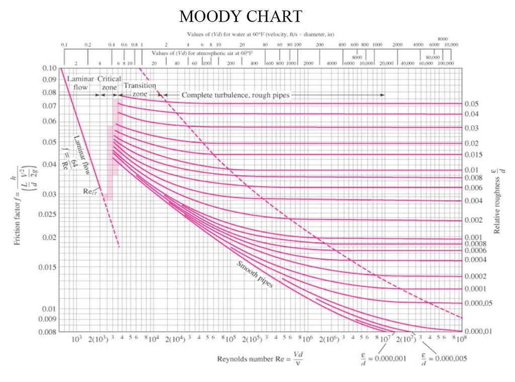
34 Problem 5 1 Steady State energy equation 2 major minor In units of ft 2 elbows Major loss Valve entrance exit - Losses dependent on Reynolds number Re = VD/ν - But, the velocity V is unknown, so we cannot find the Reynolds number, and thus we cannot find f, the friction factor We have to do some iterative procedure. Assume that the flow is fully turbulent. In this case, the friction factor is function of the surface roughness of the pipe only (independent of Re. Check Moody Diagram). For steel pipe ε= ft => ε/d= From Moody chart, choose the line corresponding to this surface roughness, choose the friction factor for fully turbulent flow. 34
35
36 Guess 1: Fully turbulent flow => f Substitute this f above. Find the velocity V = ft/s. Now verify whether this velocity really gives a fully turbulent flow. Re = ρvd/µ = Guess 2: With this Reynolds number, and the surface roughness, check Moody diagram and get a better value for f => f Substitute this f above. Find the velocity V = 11.2 ft/s. Recalculate Re. Re = 4 x 10 5 Guess 3: Use this Re and the surface roughness, find f. f=0.02 Same as above. Thus, we have reached the end of the iteration. V = 11.2 ft/s 36
37 Problem 6 V 1 and V 2 and P 1 and P 2 are not known. Mass conservation between sections 1 and 2 Bernoulli gives us another equation Rearranging and using result from mass-conservation From manometer reading we can find the pressure drop => Then calculate V 1, and the ideal discharge is given as Q = V 1 A 1 and mass flux is = ρv 1 A 1 37

38 In reality, there is a boundary layer that develops inside the venturi, the actual flow rate is slightly less than the one calculated above. This is expressed in terms of Q_actual = Cd V1 A1 The discharge coefficient depends on the Reynolds number and the area ratio of the venturi. Find Re. and knowing the area ratios, find the discharge coefficient. Use it to find Q_actual C_d ~ Q_actual = m3/s 38
39 Problem 7 P 2 is unknown, V 2 is unknown Conservation of Mass: ρv 1 A 1 = ρv 2 A 2 Bernoulli: => Consider forces on the fluid => F x = 7740 lb to the left => F y = 1910 lb upward 39
Steven Burian Civil & Environmental Engineering September 25, 2013
 Fundamentals of Engineering (FE) Exam Mechanics Steven Burian Civil & Environmental Engineering September 25, 2013 s and FE Morning ( Mechanics) A. Flow measurement 7% of FE Morning B. properties Session
FE Exam Fluids Review October 23, Important Concepts
 FE Exam Fluids Review October 3, 013 mportant Concepts Density, specific volume, specific weight, specific gravity (Water 1000 kg/m^3, Air 1. kg/m^3) Meaning & Symbols? Stress, Pressure, Viscosity; Meaning
s and FE X. A. Flow measurement B. properties C. statics D. impulse, and momentum equations E. Pipe and other internal flow 7% of FE Morning Session I
 Fundamentals of Engineering (FE) Exam General Section Steven Burian Civil & Environmental Engineering October 26, 2010 s and FE X. A. Flow measurement B. properties C. statics D. impulse, and momentum
Chapter 8: Flow in Pipes
 8-1 Introduction 8-2 Laminar and Turbulent Flows 8-3 The Entrance Region 8-4 Laminar Flow in Pipes 8-5 Turbulent Flow in Pipes 8-6 Fully Developed Pipe Flow 8-7 Minor Losses 8-8 Piping Networks and Pump
Reynolds, an engineering professor in early 1880 demonstrated two different types of flow through an experiment:
 7 STEADY FLOW IN PIPES 7.1 Reynolds Number Reynolds, an engineering professor in early 1880 demonstrated two different types of flow through an experiment: Laminar flow Turbulent flow Reynolds apparatus
Viscous Flow in Ducts
 Dr. M. Siavashi Iran University of Science and Technology Spring 2014 Objectives 1. Have a deeper understanding of laminar and turbulent flow in pipes and the analysis of fully developed flow 2. Calculate
Chapter 8: Flow in Pipes
 Objectives 1. Have a deeper understanding of laminar and turbulent flow in pipes and the analysis of fully developed flow 2. Calculate the major and minor losses associated with pipe flow in piping networks
Pipe Flow. Lecture 17
 Pipe Flow Lecture 7 Pipe Flow and the Energy Equation For pipe flow, the Bernoulli equation alone is not sufficient. Friction loss along the pipe, and momentum loss through diameter changes and corners
Lesson 6 Review of fundamentals: Fluid flow
 Lesson 6 Review of fundamentals: Fluid flow The specific objective of this lesson is to conduct a brief review of the fundamentals of fluid flow and present: A general equation for conservation of mass
Mechanical Engineering Programme of Study
 Mechanical Engineering Programme of Study Fluid Mechanics Instructor: Marios M. Fyrillas Email: eng.fm@fit.ac.cy SOLVED EXAMPLES ON VISCOUS FLOW 1. Consider steady, laminar flow between two fixed parallel
Chapter 10 Flow in Conduits
 Chapter 10 Flow in Conduits 10.1 Classifying Flow Laminar Flow and Turbulent Flow Laminar flow Unpredictable Turbulent flow Near entrance: undeveloped developing flow In developing flow, the wall shear
FLUID MECHANICS D203 SAE SOLUTIONS TUTORIAL 2 APPLICATIONS OF BERNOULLI SELF ASSESSMENT EXERCISE 1
 FLUID MECHANICS D203 SAE SOLUTIONS TUTORIAL 2 APPLICATIONS OF BERNOULLI SELF ASSESSMENT EXERCISE 1 1. A pipe 100 mm bore diameter carries oil of density 900 kg/m3 at a rate of 4 kg/s. The pipe reduces
Hydraulics. B.E. (Civil), Year/Part: II/II. Tutorial solutions: Pipe flow. Tutorial 1
, Year/Part: II/II. Tutorial solutions: Pipe flow. Tutorial 1") Hydraulics B.E. (Civil), Year/Part: II/II Tutorial solutions: Pipe flow Tutorial 1 -by Dr. K.N. Dulal Laminar flow 1. A pipe 200mm in diameter and 20km long conveys oil of density 900 kg/m 3 and viscosity
Hydraulics B.E. (Civil), Year/Part: II/II Tutorial solutions: Pipe flow Tutorial 1 -by Dr. K.N. Dulal Laminar flow 1. A pipe 200mm in diameter and 20km long conveys oil of density 900 kg/m 3 and viscosity
ρg 998(9.81) LV 50 V. d2g 0.062(9.81)
 LV 50 V. d2g 0.062(9.81)") 6.78 In Fig. P6.78 the connecting pipe is commercial steel 6 cm in diameter. Estimate the flow rate, in m 3 /h, if the fluid is water at 0 C. Which way is the flow? Solution: For water, take ρ = 998 kg/m
6.78 In Fig. P6.78 the connecting pipe is commercial steel 6 cm in diameter. Estimate the flow rate, in m 3 /h, if the fluid is water at 0 C. Which way is the flow? Solution: For water, take ρ = 998 kg/m
ACCOUNTING FOR FRICTION IN THE BERNOULLI EQUATION FOR FLOW THROUGH PIPES
 ACCOUNTING FOR FRICTION IN THE BERNOULLI EQUATION FOR FLOW THROUGH PIPES Some background information first: We have seen that a major limitation of the Bernoulli equation is that it does not account for
Q1 Give answers to all of the following questions (5 marks each):
:") FLUID MECHANICS First Year Exam Solutions 03 Q Give answers to all of the following questions (5 marks each): (a) A cylinder of m in diameter is made with material of relative density 0.5. It is moored
FLUID MECHANICS First Year Exam Solutions 03 Q Give answers to all of the following questions (5 marks each): (a) A cylinder of m in diameter is made with material of relative density 0.5. It is moored
ME 305 Fluid Mechanics I. Part 8 Viscous Flow in Pipes and Ducts. Flow in Pipes and Ducts. Flow in Pipes and Ducts (cont d)
") ME 305 Fluid Mechanics I Flow in Pipes and Ducts Flow in closed conduits (circular pipes and non-circular ducts) are very common. Part 8 Viscous Flow in Pipes and Ducts These presentations are prepared
ME 305 Fluid Mechanics I Flow in Pipes and Ducts Flow in closed conduits (circular pipes and non-circular ducts) are very common. Part 8 Viscous Flow in Pipes and Ducts These presentations are prepared
MTE 119 STATICS FINAL HELP SESSION REVIEW PROBLEMS PAGE 1 9 NAME & ID DATE. Example Problem P.1
 MTE STATICS Example Problem P. Beer & Johnston, 004 by Mc Graw-Hill Companies, Inc. The structure shown consists of a beam of rectangular cross section (4in width, 8in height. (a Draw the shear and bending
LECTURE 6- ENERGY LOSSES IN HYDRAULIC SYSTEMS SELF EVALUATION QUESTIONS AND ANSWERS
 LECTURE 6- ENERGY LOSSES IN HYDRAULIC SYSTEMS SELF EVALUATION QUESTIONS AND ANSWERS 1. What is the head loss ( in units of bars) across a 30mm wide open gate valve when oil ( SG=0.9) flow through at a
Bernoulli and Pipe Flow
 Civil Engineering Hydraulics Mechanics of Fluids Head Loss Calculations Bernoulli and The Bernoulli equation that we worked with was a bit simplistic in the way it looked at a fluid system All real systems
vector H. If O is the point about which moments are desired, the angular moment about O is given:
 The angular momentum A control volume analysis can be applied to the angular momentum, by letting B equal to angularmomentum vector H. If O is the point about which moments are desired, the angular moment
ME 309 Fluid Mechanics Fall 2010 Exam 2 1A. 1B.
 Fall 010 Exam 1A. 1B. Fall 010 Exam 1C. Water is flowing through a 180º bend. The inner and outer radii of the bend are 0.75 and 1.5 m, respectively. The velocity profile is approximated as C/r where C
ME 305 Fluid Mechanics I. Chapter 8 Viscous Flow in Pipes and Ducts
 ME 305 Fluid Mechanics I Chapter 8 Viscous Flow in Pipes and Ducts These presentations are prepared by Dr. Cüneyt Sert Department of Mechanical Engineering Middle East Technical University Ankara, Turkey
Only if handing in. Name: Student No.: Page 2 of 7
 UNIVERSITY OF TORONTO FACULTY OF APPLIED SCIENCE AND ENGINEERING FINAL EXAMINATION, DECEMBER 10, 2014 2:00 PM 2.5 HOURS CHE 211F FLUID MECHANICS EXAMINER: PROFESSOR D.G. ALLEN ANSWER ALL SEVEN (7) QUESTIONS
Chapter (6) Energy Equation and Its Applications
 Energy Equation and Its Applications") Chapter (6) Energy Equation and Its Applications Bernoulli Equation Bernoulli equation is one of the most useful equations in fluid mechanics and hydraulics. And it s a statement of the principle of conservation
Chapter (6) Energy Equation and Its Applications Bernoulli Equation Bernoulli equation is one of the most useful equations in fluid mechanics and hydraulics. And it s a statement of the principle of conservation
2 Internal Fluid Flow
 Internal Fluid Flow.1 Definitions Fluid Dynamics The study of fluids in motion. Static Pressure The pressure at a given point exerted by the static head of the fluid present directly above that point.
Signature: (Note that unsigned exams will be given a score of zero.)
") Neatly print your name: Signature: (Note that unsigned exams will be given a score of zero.) Circle your lecture section (-1 point if not circled, or circled incorrectly): Prof. Dabiri Prof. Wassgren Prof.
Neatly print your name: Signature: (Note that unsigned exams will be given a score of zero.) Circle your lecture section (-1 point if not circled, or circled incorrectly): Prof. Dabiri Prof. Wassgren Prof.
Chapter 6. Losses due to Fluid Friction
 Chapter 6 Losses due to Fluid Friction 1 Objectives ä To measure the pressure drop in the straight section of smooth, rough, and packed pipes as a function of flow rate. ä To correlate this in terms of
Angular momentum equation
 Angular momentum equation For angular momentum equation, B =H O the angular momentum vector about point O which moments are desired. Where β is The Reynolds transport equation can be written as follows:
Final 1. (25) 2. (10) 3. (10) 4. (10) 5. (10) 6. (10) TOTAL = HW = % MIDTERM = % FINAL = % COURSE GRADE =
 2. (10) 3. (10) 4. (10) 5. (10) 6. (10) TOTAL = HW = % MIDTERM = % FINAL = % COURSE GRADE =") MAE101B: Advanced Fluid Mechanics Winter Quarter 2017 http://web.eng.ucsd.edu/~sgls/mae101b_2017/ Name: Final This is a three hour open-book exam. Please put your name on the top sheet of the exam. Answer
MAE101B: Advanced Fluid Mechanics Winter Quarter 2017 http://web.eng.ucsd.edu/~sgls/mae101b_2017/ Name: Final This is a three hour open-book exam. Please put your name on the top sheet of the exam. Answer
When water (fluid) flows in a pipe, for example from point A to point B, pressure drop will occur due to the energy losses (major and minor losses).
 flows in a pipe, for example from point A to point B, pressure drop will occur due to the energy losses (major and minor losses).") PRESSURE DROP AND OSSES IN PIPE When water (luid) lows in a pipe, or example rom point A to point B, pressure drop will occur due to the energy losses (major and minor losses). A B Bernoulli equation:
PRESSURE DROP AND OSSES IN PIPE When water (luid) lows in a pipe, or example rom point A to point B, pressure drop will occur due to the energy losses (major and minor losses). A B Bernoulli equation:
Dimensions represent classes of units we use to describe a physical quantity. Most fluid problems involve four primary dimensions
 BEE 5330 Fluids FE Review, Feb 24, 2010 1 A fluid is a substance that can not support a shear stress. Liquids differ from gasses in that liquids that do not completely fill a container will form a free
150A Review Session 2/13/2014 Fluid Statics. Pressure acts in all directions, normal to the surrounding surfaces
 Fluid Statics Pressure acts in all directions, normal to the surrounding surfaces or Whenever a pressure difference is the driving force, use gauge pressure o Bernoulli equation o Momentum balance with
The Impulse-Momentum Principle
 Chapter 6 /60 The Impulse-Momentum Principle F F Chapter 6 The Impulse-Momentum Principle /60 Contents 6.0 Introduction 6. The Linear Impulse-Momentum Equation 6. Pipe Flow Applications 6.3 Open Channel
1-Reynold s Experiment
 Lect.No.8 2 nd Semester Flow Dynamics in Closed Conduit (Pipe Flow) 1 of 21 The flow in closed conduit ( flow in pipe ) is differ from this occur in open channel where the flow in pipe is at a pressure
Control Volume Revisited
 Civil Engineering Hydraulics Control Volume Revisited Previously, we considered developing a control volume so that we could isolate mass flowing into and out of the control volume Our goal in developing
Lesson 37 Transmission Of Air In Air Conditioning Ducts
 Lesson 37 Transmission Of Air In Air Conditioning Ducts Version 1 ME, IIT Kharagpur 1 The specific objectives of this chapter are to: 1. Describe an Air Handling Unit (AHU) and its functions (Section 37.1).
HOW TO GET A GOOD GRADE ON THE MME 2273B FLUID MECHANICS 1 EXAM. Common mistakes made on the final exam and how to avoid them
 HOW TO GET A GOOD GRADE ON THE MME 2273B FLUID MECHANICS 1 EXAM Common mistakes made on the final exam and how to avoid them HOW TO GET A GOOD GRADE ON THE MME 2273B EXAM Introduction You now have a lot
FE Fluids Review March 23, 2012 Steve Burian (Civil & Environmental Engineering)
") Topic: Fluid Properties 1. If 6 m 3 of oil weighs 47 kn, calculate its specific weight, density, and specific gravity. 2. 10.0 L of an incompressible liquid exert a force of 20 N at the earth s surface.
Topic: Fluid Properties 1. If 6 m 3 of oil weighs 47 kn, calculate its specific weight, density, and specific gravity. 2. 10.0 L of an incompressible liquid exert a force of 20 N at the earth s surface.
Chapter 6. Losses due to Fluid Friction
 Chapter 6 Losses due to Fluid Friction 1 Objectives To measure the pressure drop in the straight section of smooth, rough, and packed pipes as a function of flow rate. To correlate this in terms of the
Part A: 1 pts each, 10 pts total, no partial credit.
 Part A: 1 pts each, 10 pts total, no partial credit. 1) (Correct: 1 pt/ Wrong: -3 pts). The sum of static, dynamic, and hydrostatic pressures is constant when flow is steady, irrotational, incompressible,
Chapter (3) Water Flow in Pipes
 Water Flow in Pipes") Chapter (3) Water Flow in Pipes Water Flow in Pipes Bernoulli Equation Recall fluid mechanics course, the Bernoulli equation is: P 1 ρg + v 1 g + z 1 = P ρg + v g + z h P + h T + h L Here, we want to study
Chapter (3) Water Flow in Pipes Water Flow in Pipes Bernoulli Equation Recall fluid mechanics course, the Bernoulli equation is: P 1 ρg + v 1 g + z 1 = P ρg + v g + z h P + h T + h L Here, we want to study
CIVE HYDRAULIC ENGINEERING PART I Pierre Julien Colorado State University
 CIVE 401 - HYDRAULIC ENGINEERING PART I Pierre Julien Colorado State University Problems with and are considered moderate and those with are the longest and most difficult. In 2018 solve the problems with
Detailed Outline, M E 320 Fluid Flow, Spring Semester 2015
 Detailed Outline, M E 320 Fluid Flow, Spring Semester 2015 I. Introduction (Chapters 1 and 2) A. What is Fluid Mechanics? 1. What is a fluid? 2. What is mechanics? B. Classification of Fluid Flows 1. Viscous
Piping Systems and Flow Analysis (Chapter 3)
") Piping Systems and Flow Analysis (Chapter 3) 2 Learning Outcomes (Chapter 3) Losses in Piping Systems Major losses Minor losses Pipe Networks Pipes in series Pipes in parallel Manifolds and Distribution
Piping Systems and Flow Analysis (Chapter 3) 2 Learning Outcomes (Chapter 3) Losses in Piping Systems Major losses Minor losses Pipe Networks Pipes in series Pipes in parallel Manifolds and Distribution
Major and Minor Losses
 Abstract Major and Minor Losses Caitlyn Collazo, Team 2 (1:00 pm) A Technovate fluid circuit system was used to determine the pressure drop across a pipe section and across an orifice. These pressure drops
Chapter Four fluid flow mass, energy, Bernoulli and momentum
 4-1Conservation of Mass Principle Consider a control volume of arbitrary shape, as shown in Fig (4-1). Figure (4-1): the differential control volume and differential control volume (Total mass entering
CHAPTER 2 Fluid Statics
 Chapter / Fluid Statics CHPTER Fluid Statics FE-type Eam Review Problems: Problems - to -9. (C). (D). (C).4 ().5 () The pressure can be calculated using: p = γ h were h is the height of mercury. p= γ h=
FACULTY OF CHEMICAL & ENERGY ENGINEERING FLUID MECHANICS LABORATORY TITLE OF EXPERIMENT: MINOR LOSSES IN PIPE (E4)
") FACULTY OF CHEMICAL & ENERGY ENGINEERING FLUID MECHANICS LABORATORY TITLE OF EXPERIMENT: MINOR LOSSES IN PIPE (E4) 1 1.0 Objectives The objective of this experiment is to calculate loss coefficient (K
FACULTY OF CHEMICAL & ENERGY ENGINEERING FLUID MECHANICS LABORATORY TITLE OF EXPERIMENT: MINOR LOSSES IN PIPE (E4) 1 1.0 Objectives The objective of this experiment is to calculate loss coefficient (K
Chapter (3) Water Flow in Pipes
 Water Flow in Pipes") Chapter (3) Water Flow in Pipes Water Flow in Pipes Bernoulli Equation Recall fluid mechanics course, the Bernoulli equation is: P 1 ρg + v 1 g + z 1 = P ρg + v g + z h P + h T + h L Here, we want to study
Chapter (3) Water Flow in Pipes Water Flow in Pipes Bernoulli Equation Recall fluid mechanics course, the Bernoulli equation is: P 1 ρg + v 1 g + z 1 = P ρg + v g + z h P + h T + h L Here, we want to study
Mass of fluid leaving per unit time
 5 ENERGY EQUATION OF FLUID MOTION 5.1 Eulerian Approach & Control Volume In order to develop the equations that describe a flow, it is assumed that fluids are subject to certain fundamental laws of physics.
Fluid Dynamics Exam #1: Introduction, fluid statics, and the Bernoulli equation March 2, 2016, 7:00 p.m. 8:40 p.m. in CE 118
 CVEN 311-501 (Socolofsky) Fluid Dynamics Exam #1: Introduction, fluid statics, and the Bernoulli equation March 2, 2016, 7:00 p.m. 8:40 p.m. in CE 118 Name: : UIN: : Instructions: Fill in your name and
Approximate physical properties of selected fluids All properties are given at pressure kn/m 2 and temperature 15 C.
 Appendix FLUID MECHANICS Approximate physical properties of selected fluids All properties are given at pressure 101. kn/m and temperature 15 C. Liquids Density (kg/m ) Dynamic viscosity (N s/m ) Surface
Fluids. Fluids in Motion or Fluid Dynamics
 Fluids Fluids in Motion or Fluid Dynamics Resources: Serway - Chapter 9: 9.7-9.8 Physics B Lesson 3: Fluid Flow Continuity Physics B Lesson 4: Bernoulli's Equation MIT - 8: Hydrostatics, Archimedes' Principle,
3.8 The First Law of Thermodynamics and the Energy Equation
 CEE 3310 Control Volume Analysis, Sep 30, 2011 65 Review Conservation of angular momentum 1-D form ( r F )ext = [ˆ ] ( r v)d + ( r v) out ṁ out ( r v) in ṁ in t CV 3.8 The First Law of Thermodynamics and
F L U I D S Y S T E M D Y N A M I C S
 F L U I D S Y S T E M D Y N A M I C S T he proper design, construction, operation, and maintenance of fluid systems requires understanding of the principles which govern them. These principles include
Fluid Mechanics Testbank By David Admiraal
 Fluid Mechanics Testbank By David Admiraal This testbank was created for an introductory fluid mechanics class. The primary intentions of the testbank are to help students improve their performance on
Fluid Mechanics. du dy
 FLUID MECHANICS Technical English - I 1 th week Fluid Mechanics FLUID STATICS FLUID DYNAMICS Fluid Statics or Hydrostatics is the study of fluids at rest. The main equation required for this is Newton's
Experiment (4): Flow measurement
: Flow measurement") Experiment (4): Flow measurement Introduction: The flow measuring apparatus is used to familiarize the students with typical methods of flow measurement of an incompressible fluid and, at the same time
Experiment (4): Flow measurement Introduction: The flow measuring apparatus is used to familiarize the students with typical methods of flow measurement of an incompressible fluid and, at the same time
1.060 Engineering Mechanics II Spring Problem Set 4
 1.060 Engineering Mechanics II Spring 2006 Due on Monday, March 20th Problem Set 4 Important note: Please start a new sheet of paper for each problem in the problem set. Write the names of the group members
where = rate of change of total energy of the system, = rate of heat added to the system, = rate of work done by the system
 The Energy Equation for Control Volumes Recall, the First Law of Thermodynamics: where = rate of change of total energy of the system, = rate of heat added to the system, = rate of work done by the system
Hydraulics and hydrology
 Hydraulics and hydrology - project exercises - Class 4 and 5 Pipe flow Discharge (Q) (called also as the volume flow rate) is the volume of fluid that passes through an area per unit time. The discharge
Fluid Mechanics Discussion. Prepared By: Dr.Khalil M. Al-Astal Eng.Ahmed S. Al-Agha Eng.Ruba M. Awad
 Discussion Prepared By: Dr.Khalil M. Al-Astal Eng.Ahmed S. Al-Agha Eng.Ruba M. Awad 2014-2015 Chapter (1) Fluids and their Properties Fluids and their Properties Fluids (Liquids or gases) which a substance
PROPERTIES OF FLUIDS
 Unit - I Chapter - PROPERTIES OF FLUIDS Solutions of Examples for Practice Example.9 : Given data : u = y y, = 8 Poise = 0.8 Pa-s To find : Shear stress. Step - : Calculate the shear stress at various
CLASS SCHEDULE 2013 FALL
 CLASS SCHEDULE 2013 FALL Class # or Lab # 1 Date Aug 26 2 28 Important Concepts (Section # in Text Reading, Lecture note) Examples/Lab Activities Definition fluid; continuum hypothesis; fluid properties
Consider a control volume in the form of a straight section of a streamtube ABCD.
 6 MOMENTUM EQUATION 6.1 Momentum and Fluid Flow In mechanics, the momentum of a particle or object is defined as the product of its mass m and its velocity v: Momentum = mv The particles of a fluid stream
Rate of Flow Quantity of fluid passing through any section (area) per unit time
 per unit time") Kinematics of Fluid Flow Kinematics is the science which deals with study of motion of liquids without considering the forces causing the motion. Rate of Flow Quantity of fluid passing through any section
Kinematics of Fluid Flow Kinematics is the science which deals with study of motion of liquids without considering the forces causing the motion. Rate of Flow Quantity of fluid passing through any section
Applied Fluid Mechanics
 Applied Fluid Mechanics 1. The Nature of Fluid and the Study of Fluid Mechanics 2. Viscosity of Fluid 3. Pressure Measurement 4. Forces Due to Static Fluid 5. Buoyancy and Stability 6. Flow of Fluid and
ME19b. FINAL REVIEW SOLUTIONS. Mar. 11, 2010.
 ME19b. FINAL REVIEW SOLTIONS. Mar. 11, 21. EXAMPLE PROBLEM 1 A laboratory wind tunnel has a square test section with side length L. Boundary-layer velocity profiles are measured at two cross-sections and
Forced Convection: Inside Pipe HANNA ILYANI ZULHAIMI
 + Forced Convection: Inside Pipe HANNA ILYANI ZULHAIMI + OUTLINE u Introduction and Dimensionless Numbers u Heat Transfer Coefficient for Laminar Flow inside a Pipe u Heat Transfer Coefficient for Turbulent
BACHELOR OF TECHNOLOGY IN MECHANICAL ENGINEERING (COMPUTER INTEGRATED MANUFACTURING)
") No. of Printed Pages : 6 BME-028 BACHELOR OF TECHNOLOGY IN MECHANICAL ENGINEERING (COMPUTER INTEGRATED MANUFACTURING) Term-End Examination December, 2011 00792 BME-028 : FLUID MECHANICS Time : 3 hours
No. of Printed Pages : 6 BME-028 BACHELOR OF TECHNOLOGY IN MECHANICAL ENGINEERING (COMPUTER INTEGRATED MANUFACTURING) Term-End Examination December, 2011 00792 BME-028 : FLUID MECHANICS Time : 3 hours
Conservation of Momentum using Control Volumes
 Conservation of Momentum using Control Volumes Conservation of Linear Momentum Recall the conservation of linear momentum law for a system: In order to convert this for use in a control volume, use RTT
P = ρ{ g a } + µ 2 V II. FLUID STATICS
 II. FLUID STATICS From a force analysis on a triangular fluid element at rest, the following three concepts are easily developed: For a continuous, hydrostatic, shear free fluid: 1. Pressure is constant
Chapter 6 The Impulse-Momentum Principle
 Chapter 6 The Impulse-Momentum Principle 6. The Linear Impulse-Momentum Equation 6. Pipe Flow Applications 6.3 Open Channel Flow Applications 6.4 The Angular Impulse-Momentum Principle Objectives: - Develop
Atmospheric pressure. 9 ft. 6 ft
 Name CEE 4 Final Exam, Aut 00; Answer all questions; 145 points total. Some information that might be helpful is provided below. A Moody diagram is printed on the last page. For water at 0 o C (68 o F):
CEE 3310 Control Volume Analysis, Oct. 10, = dt. sys
 CEE 3310 Control Volume Analysis, Oct. 10, 2018 77 3.16 Review First Law of Thermodynamics ( ) de = dt Q Ẇ sys Sign convention: Work done by the surroundings on the system < 0, example, a pump! Work done
OE4625 Dredge Pumps and Slurry Transport. Vaclav Matousek October 13, 2004
 OE465 Vaclav Matousek October 13, 004 1 Dredge Vermelding Pumps onderdeel and Slurry organisatie Transport OE465 Vaclav Matousek October 13, 004 Dredge Vermelding Pumps onderdeel and Slurry organisatie
PIPING SYSTEMS. Pipe and Tubing Standards Sizes for pipes and tubes are standardized. Pipes are specified by a nominal diameter and a schedule number.
 PIPING SYSTEMS In this chapter we will review some of the basic concepts associated with piping systems. Topics that will be considered in this chapter are - Pipe and tubing standards - Effective and hydraulic
Formulae that you may or may not find useful. E v = V. dy dx = v u. y cp y = I xc/a y. Volume of an entire sphere = 4πr3 = πd3
 CE30 Test 1 Solution Key Date: 26 Sept. 2017 COVER PAGE Write your name on each sheet of paper that you hand in. Read all questions very carefully. If the problem statement is not clear, you should ask
CEE 3310 Control Volume Analysis, Oct. 7, D Steady State Head Form of the Energy Equation P. P 2g + z h f + h p h s.
 CEE 3310 Control Volume Analysis, Oct. 7, 2015 81 3.21 Review 1-D Steady State Head Form of the Energy Equation ( ) ( ) 2g + z = 2g + z h f + h p h s out where h f is the friction head loss (which combines
Reference : McCabe, W.L. Smith J.C. & Harriett P., Unit Operations of Chemical
 1 Course materials (References) Textbook: Welty J. R., Wicks, C. E., Wilson, R. E., & Rorrer, G., Fundamentals of Momentum Heat, and Mass Transfer, 4th Edition, John Wiley & Sons.2000 Reference : McCabe,
ME3560 Tentative Schedule Spring 2019
 ME3560 Tentative Schedule Spring 2019 Week Number Date Lecture Topics Covered Prior to Lecture Read Section Assignment Prep Problems for Prep Probs. Must be Solved by 1 Monday 1/7/2019 1 Introduction to
Exam #2: Fluid Kinematics and Conservation Laws April 13, 2016, 7:00 p.m. 8:40 p.m. in CE 118
 CVEN 311-501 (Socolofsky) Fluid Dynamics Exam #2: Fluid Kinematics and Conservation Laws April 13, 2016, 7:00 p.m. 8:40 p.m. in CE 118 Name: : UIN: : Instructions: Fill in your name and UIN in the space
Hydraulics for Urban Storm Drainage
 Urban Hydraulics Hydraulics for Urban Storm Drainage Learning objectives: understanding of basic concepts of fluid flow and how to analyze conduit flows, free surface flows. to analyze, hydrostatic pressure
Applied Fluid Mechanics
 Applied Fluid Mechanics 1. The Nature of Fluid and the Study of Fluid Mechanics 2. Viscosity of Fluid 3. Pressure Measurement 4. Forces Due to Static Fluid 5. Buoyancy and Stability 6. Flow of Fluid and
ME332 FLUID MECHANICS LABORATORY (PART I)
") ME332 FLUID MECHANICS LABORATORY (PART I) Mihir Sen Department of Aerospace and Mechanical Engineering University of Notre Dame Notre Dame, IN 46556 Version: January 14, 2002 Contents Unit 1: Hydrostatics
ME332 FLUID MECHANICS LABORATORY (PART I) Mihir Sen Department of Aerospace and Mechanical Engineering University of Notre Dame Notre Dame, IN 46556 Version: January 14, 2002 Contents Unit 1: Hydrostatics
Lecture 3 The energy equation
 Lecture 3 The energy equation Dr Tim Gough: t.gough@bradford.ac.uk General information Lab groups now assigned Timetable up to week 6 published Is there anyone not yet on the list? Week 3 Week 4 Week 5
5 ENERGY EQUATION OF FLUID MOTION
 5 ENERGY EQUATION OF FLUID MOTION 5.1 Introduction In order to develop the equations that describe a flow, it is assumed that fluids are subject to certain fundamental laws of physics. The pertinent laws
CVE 372 HYDROMECHANICS EXERCISE PROBLEMS
 VE 37 HYDROMEHNIS EXERISE PROLEMS 1. pump that has the characteristic curve shown in the accompanying graph is to be installed in the system shown. What will be the discharge of water in the system? Take
FLUID MECHANICS. Dynamics of Viscous Fluid Flow in Closed Pipe: Darcy-Weisbach equation for flow in pipes. Major and minor losses in pipe lines.
 FLUID MECHANICS Dynamics of iscous Fluid Flow in Closed Pipe: Darcy-Weisbach equation for flow in pipes. Major and minor losses in pipe lines. Dr. Mohsin Siddique Assistant Professor Steady Flow Through
ME3560 Tentative Schedule Fall 2018
 ME3560 Tentative Schedule Fall 2018 Week Number 1 Wednesday 8/29/2018 1 Date Lecture Topics Covered Introduction to course, syllabus and class policies. Math Review. Differentiation. Prior to Lecture Read
Physics 3 Summer 1990 Lab 7 - Hydrodynamics
 Physics 3 Summer 1990 Lab 7 - Hydrodynamics Theory Consider an ideal liquid, one which is incompressible and which has no internal friction, flowing through pipe of varying cross section as shown in figure
Basic Fluid Mechanics
 Basic Fluid Mechanics Chapter 5: Application of Bernoulli Equation 4/16/2018 C5: Application of Bernoulli Equation 1 5.1 Introduction In this chapter we will show that the equation of motion of a particle
Basic Fluid Mechanics
 Basic Fluid Mechanics Chapter 6A: Internal Incompressible Viscous Flow 4/16/2018 C6A: Internal Incompressible Viscous Flow 1 6.1 Introduction For the present chapter we will limit our study to incompressible
M E 320 Professor John M. Cimbala Lecture 24
 M E 30 Professor John M. Cimbala Lecture 4 Today, we will: Discuss pump performance curves Discuss how to match a pump and a piping system, and do some example problems. Pump Performance a. Pump performance
Aerodynamics. Basic Aerodynamics. Continuity equation (mass conserved) Some thermodynamics. Energy equation (energy conserved)
 Some thermodynamics. Energy equation (energy conserved)") Flow with no friction (inviscid) Aerodynamics Basic Aerodynamics Continuity equation (mass conserved) Flow with friction (viscous) Momentum equation (F = ma) 1. Euler s equation 2. Bernoulli s equation
Flow with no friction (inviscid) Aerodynamics Basic Aerodynamics Continuity equation (mass conserved) Flow with friction (viscous) Momentum equation (F = ma) 1. Euler s equation 2. Bernoulli s equation
Signature: (Note that unsigned exams will be given a score of zero.)
") Neatly print your name: Signature: (Note that unsigned exams will be given a score of zero.) Circle your lecture section (-1 point if not circled, or circled incorrectly): Prof. Dabiri Prof. Wassgren Prof.
Neatly print your name: Signature: (Note that unsigned exams will be given a score of zero.) Circle your lecture section (-1 point if not circled, or circled incorrectly): Prof. Dabiri Prof. Wassgren Prof.
Compressible Duct Flow with Friction
 Compressible Duct Flow with Friction We treat only the effect of friction, neglecting area change and heat transfer. The basic assumptions are 1. Steady one-dimensional adiabatic flow 2. Perfect gas with
Chapter 5 Control Volume Approach and Continuity Equation
 Chapter 5 Control Volume Approach and Continuity Equation Lagrangian and Eulerian Approach To evaluate the pressure and velocities at arbitrary locations in a flow field. The flow into a sudden contraction,
Physics 201 Chapter 13 Lecture 1
 Physics 201 Chapter 13 Lecture 1 Fluid Statics Pascal s Principle Archimedes Principle (Buoyancy) Fluid Dynamics Continuity Equation Bernoulli Equation 11/30/2009 Physics 201, UW-Madison 1 Fluids Density