US Safety Couplings. Partner for Performance
|
|
|
- Trevor Black
- 5 years ago
- Views:
Transcription


1 US Safety Couplings Partner for Performance


2 Welcome to your system supplier for every aspect of power transmission RINGFEDER POWER TRANSMISSION We say what we mean and mean what we say. We see things from our customers perspective. We are considerate of our employees and their families as well as our environment and the society. RINGFEDER POWER TRANSMISSION is the global market leader in the niche markets of drive technology and is well regarded for its customer-specific, application-oriented solutions that ensure excellent and failure-free operation for its clients. 2


3 Mars Rover: Courtesy NASA/ JPL-Caltech We offer locking devices, couplings, bearing housings and damping technology for OEMs but also for the final customer under our strong brand names RINGFEDER, TSCHAN, HENFEL and GERWAH. Our brand ECOLOC supplies reliable products off the shelf. We not only provide competent advice to our customers on the basis of our 90 years of experience but also develop innovative ideas in cooperation with them. This is part of our aspiration to be a Partner for Performance. Around the power transmission we promise Excellent know-how for our challenging customers Best cost-benefit ratio Short reaction times and a high product availability 3
4 Content 02 Corporate Image Basics 06 Information DXM/E Series 28 Characteristics 30 GERWAH DXM/E-CI 32 GERWAH DXM/E-OI 34 GERWAH DXM/E-KK DXR/L Series 08 Characteristics 10 GERWAH DXR/L-Fl 36 Technical Information 44 Fax Inquiry DXM/C(L) Series 12 Characteristics 14 GERWAH DXM/C-FK 16 GERWAH DXM/C-FI 18 GERWAH DXM/CL-FK 20 GERWAH DXM/CL-FI 47 Product Range RINGFEDER POWER TRANSMISSION DXM/CD Series 22 Characteristics 24 GERWAH DXM/CD-FK 26 GERWAH DXM/CD-FI DXR/B Series and DXR/E Series on request available All technical details and information are non-binding and cannot be used as a basis for legal claims. The user is obligated to determine whether the represented products meet his requirements. We reserve the right at all times to carry out modifications in the interests of technical progress. Upon the issue of this catalogue all previous brochures and questionnaires on the products displayed are no longer valid. 4

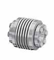
5 Series DXR/L Series Page 10 Backlash-free safety coupling with a flange designed for the direct mounting of sprocket wheels, pulleys, gear wheels and similar fittings Page 14 DXM/C(L) Series Backlash-free safety coupling with a flange and ball bearing for the direct mounting of sprocket wheels, pulleys, gear wheels and similar fittings Page 24 DXM/CD Series Backlash-free safety coupling with a flange and robust, double ball bearing for the direct mounting of sprocket wheels, pulleys, gear wheels and similar fittings Designed for higher loads DXM/E Series Page 30 Backlash-free safety coupling, designed to connect two shafts equipped with an elastomeric spider which serves as a torsionally flexible compensation element High damping characteristic Compensation of axial, radial and angular shaft misalignment 5
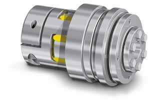
6 Basics Backlash-free Safety Couplings GERWAH Backlash-free Safety Couplings are precision torque limiters with different functional principles for overloads: Machine and system protection High-speed disengagement within 2-4 msec. Minimal residual friction Process control Accurate adjustment of disengaging torque Signalling of overloads Process accuracy Backlash-free torque transmission Excellent disengagement repeatability after long downtimes Easy handling High dynamic Low mass moment of inertia Specific customer solutions High flexibility through modular design Customers benefit Higher machine availability, increased productivity and profitability Lightweight construction possible, low masses, flexibility and dynamic of the machine are increasing, energy costs are reduced Machine parts can be used optimal because peak loads have no chance No damage by large destructive forces (e.g. in a collision) Long durability, i.e. constant production quality, longer machine operating times, better amortization 6
7 Basics The principle of the spring-loaded form closure as an overload protection Balls detent system - unlatching position Balls detent system - latching position Single position re-engagement Multi position re-engagement Single position re-engagement Multi position re-engagement 7

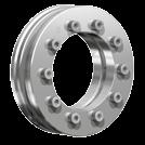
8 Series DXR/L Single position re-engagement / multi position re-engagement - backlash-free Characteristics Backlash-free safety coupling with a flange for the direct mounting of sprocket wheels, pulleys, gear wheels and similar fittings Advantages Backlash-free transmission of the torque Fast cut-off within 2-4 msec. Signal delivery at overload possible with a proximity switch Compact construction Low moment of inertia Marginal residual friction after disengaging High durability 8


9 Series GERWAH DXR/L-Fl With flange hub inner cone Torque ft-lbs Page 10 9
10 GERWAH DXR/L-Fl with flange hub - inner cone hub Single position re-engagement / multi position re-engagement - backlash-free Dimensions d 1min = Min. bore diameter d 1max = Max. bore diameter A = Max. outer diameter C = Pitch circle diameter D 4 = Outer diameter hub D F = Center diameter K 2 = Clamping length L = Total length L 1 = Length of coupling N = Distance between shift ring and coupling overhang Z = Depth of center value S = Disengagement travel n G1 = Quantity of threads G1 n Sc2 = Quantity of clamping screws D G2 D G1 ; D G2 = Thread T G1 = Depth of thread G1 Dimensions Size d 1 min-max A C D 4 D F K 2 L L 1 N Z S n G1 x D G1 T G1 n Sc2 x D G2 inch inch inch inch inch inch inch inch x M x M x M x M x M x M x M x M x M x M x M x M x M x M x M x M x M x M x M x M16 Ordering example: GERWAH DXR/L-Fl Type Size Bore diameter d 1 ft-lbs Version Functional principle DXR/L-Fl a C Torque range: a, b or c Functional principle: C = Single position re-engagement (360 ) D = Multi position re-engagement ft-lbs = Torque requested 10
11 GERWAH DXR/L-Fl with flange hub - inner cone hub Single position re-engagement / multi position re-engagement - backlash-free Z L1 L Technical Data A C DF d1 T A2 = Tightened torque of clamping screw D G2 T KN (a) = Min./Max. adjustment value for T (vers. a) T KN (b) = Min./Max. adjustment value for T (vers. b) T KN (c) = Min./Max. adjustment value for T (vers. c) J = Total moment of inertia n max = Max. rotation speed Gw = Weight DG1 DG2 TG1 S Sectional view Technical Data Size T A2 T KN (a) min-max T KN (b) min-max T KN (c) min-max J n max Gw ft-lbs ft-lbs ft-lbs ft-lbs lbs-in 2 rpm lbs The shaft tolerance must be within the fit tolerance g6 or h7 Metal bellows and servo-insert version available on request 11

12 Series DXM/C(L) Multi position re-engagement / single position re-engagement - backlash-free Characteristics Backlash-free safety coupling with a flange hub and ball bearing for the direct mounting of sprocket wheels, pulleys, gear wheels and similar fittings Advantages Backlash-free transmission of the torque Fast cut-off within 2-4 msec. Signal delivery at overload possible with a proximity switch Compact construction Low moment of inertia Marginal residual friction after disengaging High durability 12


13 Series DXM/C(L) Series GERWAH DXM/C-FK Short hub with flange hub parallel key Torque ft-lbs Page 14 Series GERWAH DXM/C-FI Short hub with flange hub cone hub Torque ft-lbs Page 16 Series GERWAH DXM/CL-FK Long hub with flange hub keyway hub for use in wide driving elements or objects with small diameters Sleeve bearings, needle bearings and ball bearings are additionally suitable to support the driving element on long hubs Torque ft-lbs Page 18 Series GERWAH DXM/CL-FI Long hub with flange hub cone hub for use in wide driving elements or objects with small diameters Sleeve bearings, needle bearings and ball bearings are additionally suitable to support the driving element on long hubs Torque ft-lbs Page 20 13
14 GERWAH DXM/C-FK short hub with flange hub keyway hub Multi position re-engagement / single position re-engagement - backlash-free Dimensions d 1kmin = Min. bore diameter with keyway acc. to DIN d 1kmax = Max. bore diameter with keyway acc. to DIN d 1kmax* = Max. bore diameter with keyway acc. to DIN A = Max. outer diameter C = Pitch circle diameter D 1 = Outer diameter hub D 2 = Outer diameter hub D F = Center diameter L = Total length N = Distance between shift ring and coupling overhang O = Length of shift ring Z = Depth of center value S = Disengagement travel n Sc1 = Quantity of clamping screws D G1 D G1 = Thread T G1 = Depth of thread G1 Dimensions Size d 1k min-max d 1kmax* A C D 1 D 2 D F L N O Z S n Sc1 x D G1 T G1 inch inch inch inch inch inch inch h x M h x M h x M h x M h x M Ordering example: GERWAH DXM/C-FK Type Size Bore diameter d 1k ft-lbs Version Functional principle DXM/C-FK b C Torque range: a,b or c Functional principle: C = Single position re-engagement (360 ) D = Multi position re-engagement (Grid spacing 15 ) ft-lbs = Torque requested 14
15 GERWAH DXM/C-FK short hub with flange hub keyway hub Multi position re-engagement / single position re-engagement - backlash-free L Technical Data Z O N T KN (a) = Min./Max. adjustment value for T (vers. a) T KN (b) = Min./Max. adjustment value for T (vers. b) T KN (c) = Min./Max. adjustment value for T (vers. c) J N = Moment of inertia hub side J F = Moment of inertia on thrust flange side n max = Max. rotation speed Gw = Weight DG1 D1 C DF d1 D2 A TG1 S Sectional view Technical Data Size T KN (a) min-max T KN (b) min-max T KN (c) min-max J N J F n max Gw ft-lbs ft-lbs ft-lbs 10-3 lbs-in lbs-in 2 rpm lbs
16 GERWAH DXM/C-FI short hub with flange hub inner cone hub Multi position re-engagement / single position re-engagement - backlash-free Dimensions d 1min d 1max A C D 1 D 2 D 4 D F K SH K 2 L L 1 N O Z S = Min. bore diameter = Max. bore diameter = Max. outer diameter = Pitch circle diameter = Outer diameter hub = Outer diameter hub = Outer diameter hub = Center diameter = Wide of srew head = Clamping length = Total length = Length of coupling = Distance between shift ring and coupling overhang = Length of shift ring = Depth of center value = Disengagement travel n Sc1 = Quantity of clamping screws D G1 D G1 ; D G2 = Thread T G1 n Sc2 = Depth of thread G1 = Quantity of clamping screws D G2 Dimensions Size d 1 min-max A C D 1 D 2 D 4 D F K 2 K SH L L 1 N O Z S n Sc1 x D G1 T G1 n Sc2 x D G2 inch inch inch inch inch inch inch inch h x M x M h x M x M h x M x M h x M x M h x M x M6 Ordering example: GERWAH DXM/C-FI Type Size Bore diameter d 1 ft-lbs Version Functional principle DXM/C-FI b C Torque range: a, b or c Functional principle: C = Single position re-engagement (360 ) D = Multi position re-engagement (Grid spacing 15 ) ft-lbs = Torque requested 16
17 GERWAH DXM/C-FI short hub with flange hub inner cone hub Multi position re-engagement / single position re-engagement - backlash-free D1 C DF d1 Z L L1 O N K2 D4 D2 A Technical Data T A2 = Tightened torque of clamping screw D G2 T KN (a) = Min./Max. adjustment value for T (vers. a) T KN (b) = Min./Max. adjustment value for T (vers. b) T KN (c) = Min./Max. adjustment value for T (vers. c) J N = Moment of inertia hub side J F = Moment of inertia on thrust flange side n max = Max. rotation speed Gw = Weight DG1 DG2 TG1 S Sectional view Technical Data Size T A2 T KN (a) min-max T KN (b) min-max T KN (c) min-max J N J F n max Gw ft-lbs ft-lbs ft-lbs ft-lbs 10-3 lbs-in lbs-in 2 rpm lbs
18 GERWAH DXM/CL-FK long hub with flange hub keyway hub Multi position re-engagement / single position re-engagement - backlash-free Dimensions d 1kmin = Min. bore diameter with keyway acc. to DIN d 1kmax = Max. bore diameter with keyway acc. to DIN d 1kmax* = Max. bore diameter with keyway acc. to DIN A = Max. outer diameter C = Pitch circle diameter D 1 = Outer diameter hub D 2 = Outer diameter hub D 3 = Outer diameter hub D F = Center diameter L = Total length L 2 = Length on the hub N = Distance between shift ring and coupling overhang O = Length of shift ring Z = Depth of center value S = Disengagement travel n Sc1 = Quantity of clamping screws D G1 D G1 = Thread T G1 = Depth of thread G1 Dimensions Size d 1k min-max d 1kmax* A C D 1 D 2 D 3 D F L L 2 N O Z S n Sc1 x D G1 T G1 inch inch inch inch inch inch inch h h x M h h x M h h x M h h x M h h x M Ordering example: GERWAH DXM/CL-FK Type Size Bore diameter d 1k ft-lbs Version Functional principle DXM/CL-FK b C Torque range: a, b or c Functional principle: C = Single position re-engagement (360 ) D = Multi position re-engagement (Grid spacing 15 ) ft-lbs = Torque requested 18
19 GERWAH DXM/CL-FK long hub with flange hub keyway hub Multi position re-engagement / single position re-engagement - backlash-free L Z O N Technical Data D1 C DF D3 d1 L2 D2 A T KN (a) = Min./Max. adjustment value for T (vers. a) T KN (b) = Min./Max. adjustment value for T (vers. b) T KN (c) = Min./Max. adjustment value for T at (vers. c) J N = Moment of inertia hub side J F = Moment of inertia on thrust flange side n max = Max. rotation speed Gw = Weight DG1 TG1 S Sectional view Technical Data T KN (a) T KN (b) T KN (c) Size min-max min-max min-max J N J F n max Gw ft-lbs ft-lbs ft-lbs 10-3 lbs-in lbs-in 2 rpm lbs
20 GERWAH DXM/CL-FI long hub with flange hub inner cone hub Multi position re-engagement / single position re-engagement - backlash-free Dimensions d 1min = Min. bore diameter d 1max = Max. bore diameter A = Max. outer diameter C = Pitch circle diameter D 1 = Outer diameter hub D 2 = Outer diameter hub D 3 = Outer diameter hub D 4 = Outer diameter hub D F = Center diameter K 2 = Clamping length L = Total length L 1 = Length of coupling L 2 = Length on the hub N = Distance between shift ring and coupling overhang O = Length of shift ring Z = Depth of center value S = Disengagement travel n G1 = Quantity of threads G1 D G1 ; D G2 = Thread T G1 = Depth of thread G1 n Sc2 = Quantity of clamping screws D G2 Dimensions Size d 1 min-max A C D 1 D 2 D 3 D 4 D F K 2 L L 1 L 2 N O Z S n G1 x D G1 T G1 n Sc2 x D G2 inch inch inch inch inch h h x M x M h h x M x M h h x M x M h h x M x M h h x M x M6 Ordering example: GERWAH DXM/CL-FI Type Size Bore diameter d 1 ft-lbs Version Functional principle DXM/CL-FI b C Torque range: a, b or c Functional principle: C = Single position re-engagement (360 ) D = Multi position re-engagement (Grid spacing 15 ) ft-lbs = Torque requested 20
21 GERWAH DXM/CL-FI long hub with flange hub inner cone hub Multi position re-engagement / single position re-engagement - backlash-free L Technical Data D1 C DF D3 d1 Z L2 L1 O N K2 D4 D2 A T A2 = Tightened torque of clamping screw D G2 T KN (a) = Min./Max. adjustment value for T (vers. a) T KN (b) = Min./Max. adjustment value for T (vers. b) T KN (c) = Min./Max. adjustment value for T (vers. c) J N J F n max Gw = Moment of inertia hub side = Moment of inertia on thrust flange side = Max. rotation speed = Weight DG1 DG2 TG1 S Sectional view Technical Data T KN (a) T KN (b) T KN (c) Size T A2 min-max min-max min-max J N J F n max Gw ft-lbs ft-lbs ft-lbs ft-lbs 10-3 lbs-in lbs-in 2 rpm lbs
22 Series DXM/CD double mounted Multi position re-engagement / single position re-engagement - backlash-free Characteristics Backlash-free safety coupling with a flange hub and robust, double ball bearing for the direct mounting of sprocket wheels, pulleys, gear wheels and similar fittings Designed for higher loads Advantages Backlash-free transmission of the torque Fast cut-off within 2-4 msec. Signal delivery at overload possible with a proximity switch Compact construction Low moment of inertia Marginal residual friction after disengaging High durability 22


23 Series DXM/CD double mounted Series GERWAH DXM/CD-FK With flange hub keyway hub Torque ft-lbs Page 24 Series GERWAH DXM/CD-FI With flange hub cone hub Torque ft-lbs Page 26 23
24 GERWAH DXM/CD-FK double mounted; with flange hub keyway hub Multi position re-engagement / single position re-engagement - backlash-free Dimensions d 1kmin = Min. bore diameter with keyway acc. to DIN d 1kmax = Max. bore diameter with keyway acc. to DIN d 1kmax* = Max. bore diameter with keyway acc. to DIN A C D 1 D 2 D F L N O Z S = Max. outer diameter = Pitch circle diameter = Outer diameter hub = Outer diameter hub = Center diameter = Total length = Distance between shift ring and coupling overhang = Length of shift ring = Depth of center value = Disengagement travel n Sc1 = Quantity of clamping screws D G1 D G1 = Thread T G1 = Depth of thread G1 Dimensions Size d 1k min-max d 1kmax* A C D 1 D 2 D F L N O Z S n Sc1 x D G1 T G1 inch inch inch inch inch inch inch h x M h x M h x M h x M h x M Ordering example: GERWAH DXM/CD-FK Type Size Bore diameter d 1k ft-lbs Version Functional principle DXM/CD-FK b C Torque range: a, b or c Functional principle: C = Single position re-engagement (360 ) D = Multi position re-engagement (Grid spacing 15 ) ft-lbs = Torque requested 24
25 GERWAH DXM/CD-FK double mounted; with flange hub keyway hub Multi position re-engagement / single position re-engagement - backlash-free L Technical Data Z O N T KN (a) = Min./Max. adjustment value for T (vers. a) T KN (b) = Min./Max. adjustment value for T (vers. b) T KN (c) = Min./Max. adjustment value for T (vers. c) J N = Moment of inertia hub side J F = Moment of inertia on thrust flange side n max = Max. rotation speed Gw = Weight DG1 D1 C DF d1 D2 A TG1 S Sectional view Technical Data T KN (a) T KN (b) T KN (c) Size min-max min-max min-max J N J F n max Gw ft-lbs ft-lbs ft-lbs 10-3 lbs-in lbs-in 2 rpm lbs
26 GERWAH DXM/CD-FI double mounted; with flange hub cone hub Multi position re-engagement / single position re-engagement - backlash-free Dimensions d 1min d 1max A C D 1 D 2 D 4 D F K 2 L L 1 N O Z S = Min. bore diameter = Max. bore diameter = Max. outer diameter = Pitch circle diameter = Outer diameter hub = Outer diameter hub = Outer diameter hub = Center diameter = Clamping length = Total length = Length of coupling = Distance between shift ring and coupling overhang = Length of shift ring = Depth of center value = Disengagement travel n Sc1 = Quantity of clamping screws D G1 D G1 ; D G2 = Thread T G1 n Sc2 = Depth of thread G1 = Quantity of clamping screws D G2 Dimensions Size d 1 min-max A C D 1 D 2 D 4 D F K 2 L L 1 N O Z S n Sc1 x D G1 T G1 n Sc2 x D G2 inch inch inch inch inch inch inch h x M x M h x M x M h x M x M h x M x M h x M x M6 Ordering example: GERWAH DXM/CD-FI Type Size Bore diameter d 1 ft-lbs Version Functional principle DXM/CD-FI b C Torque range: a, b or c Functional principle: C = Single position re-engagement (360 ) D = Multi position re-engagement (Grid spacing 15 ) ft-lbs = Torque requested 26
27 GERWAH DXM/CD-FI double mounted; with flange hub cone hub Multi position re-engagement / single position re-engagement - backlash-free L Technical Data L1 D1 C DF d1 Z O N D4 D2 A T A2 = Tightened torque of clamping screw D G2 T KN (a) = Min./Max. adjustment value for T (vers. a) T KN (b) = Min./Max. adjustment value for T (vers. b) T KN (c) = Min./Max. adjustment value for T (vers. c) J N = Moment of inertia hub side J F = Moment of inertia on thrust flange side n max = Max. rotation speed Gw = Weight K2 DG1 DG2 TG1 S Sectional view Technical Data Size T A2 T KN (a) min-max T KN (b) min-max T KN (c) min-max J N J F n max Gw ft-lbs ft-lbs ft-lbs ft-lbs 10-3 lbs-in lbs-in 2 rpm lbs
28 Series DXM/E Multi position re-engagement / single position re-engagement - backlash-free Characteristics Safety coupling, two-shaft version with an elastomeric spider as a flexible compensation element High damping characteristic Compensation of axial, radial and angular shaft misalignment Advantages Backlash-free transmission of the torque Fast cut-off within 2-4 msec. Signal delivery at overload possible with a proximity switch Compact construction Low moment of inertia Marginal residual friction after disengaging High durability 28


29 Series DXM/E Series GERWAH DXM/E-CI With clamping hub - cone hub for easy assembly / disassembly Torque ft-lbs Page 30 Series GERWAH DXM/E-OI With shrink disc hub cone hub Torque ft-lbs Page 32 Series GERWAH DXM/E-KK With keyway hub - keyway hub Torque ft-lbs Page 34 29
30 GERWAH DXM/E-CI elastomeric spider with clamping hub inner cone hub Multi position re-engagement / single position re-engagement - backlash-free Dimensions d 1,2min = Min. bore diameter d 1,2max = Max. bore diameter A = Max. outer diameter D 1 = Outer diameter hub D 2 = Outer diameter hub D 3 = Outer diameter hub D 4 = Outer diameter hub E 2 = Max. rack length of shaft l = Distance between center screw hole and hub end K 2 = Clamping length L = Total length L 1 = Length of coupling L 2 = Length on the hub N = Distance between shift ring and coupling overhang O = Length of shift ring S = Disengagement travel n Sc1 = Quantity of clamping screws D G1 D G1 ; D G2 = Thread n Sc2 = Quantity of clamping screws D G2 Dimensions Size d 1 min-max d 2 min-max A D 1 D 2 D 3 D 4 E 2 I K 2 L L 1 L 2 N O S n Sc1 x D G1 n Sc2 x D G2 inch x M6 6 x M x M8 6 x M x M8 8 x M x M8 8 x M x M12 12 x M6 Ordering example: GERWAH DXM/E-Cl Type Size Bore diameter d 1 Bore diameter d 2 ft-lbs Version Functional principle DXM/E-CI b C Torque range: a, b or c Functional principle: C = Single position re-engagement (360 ) D = Multi position re-engagement (Grid spacing 15 ) ft-lbs = Torque requested 30
31 GERWAH DXM/E-CI elastomeric spider with clamping hub inner cone hub Multi position re-engagement / single position re-engagement - backlash-free Technical Data L D1 D3 d1 DG1 L2 L1 O N E2 K2 d2 D4 D2 A DG2 T A1 = Tightened torque of clamping screw D G1 T A2 = Tightened torque of clamping screw D G2 T KN (a) = Min./Max. adjustment value for T (vers. a) T KN (b) = Min./Max. adjustment value for T (vers. b) T KN (c) = Min./Max. adjustment value for T (vers. c) Ka = Max. permissible axial misalignment Kr = Max. approved misalignment radial with elastomer 92ShA/98ShA Kw = Max. approved misalignment angular with elastomer 92ShA/98ShA J N = Moment of inertia hub side J F = Moment of inertia on thrust flange side n max = Max. rotation speed Gw = Weight l S Sectional view Technical Data T KN (a) T KN (b) T KN (c) ΔKr ΔKw Size T A1 T A2 min-max min-max min-max ΔKa (92ShA) (98ShA) (92ShA) (98ShA) J N J F n max Gw ft-lbs ft-lbs ft-lbs ft-lbs ft-lbs inch inch inch 10-3 lbs-in lbs-in 2 rpm lbs

32 GERWAH DXM/E-OI elastomeric spider with outer cone hub inner cone hub Multi position re-engagement / single position re-engagement - backlash-free Dimensions d 1,2min d 1,2max A D 1 D 2 D 3 D 4 E 2 K 2 L L 1 L 2 N O S = Min. bore diameter = Max. bore diameter = Max. outer diameter = Outer diameter hub = Outer diameter hub = Outer diameter hub = Outer diameter hub = Max. rack length of shaft = Clamping length = Total length = Length of coupling = Length on the hub = Distance between shift ring and coupling overhang = Length of shift ring = Disengagement travel n Sc1 = Quantity of clamping screws D G1 D G1 ; D G2 = Thread n Sc2 = Quantity of clamping screws D G2 Dimensions Size d 1 min-max d 2 min-max A D 1 D 2 D 3 D 4 E 2 K 2 L L 1 L 2 N O S n Sc1 x D G1 n Sc2 x D G2 inch x M5 6 x M x M5 6 x M x M5 8 x M x M8 8 x M x M10 8 x M6 Ordering example: GERWAH DXM/E-OI Type Size Bore diameter d 1 Bore diameter d 2 ft-lbs Version Functional principle DXM/E-OI b C Torque range: a, b or c Functional principle: C = Single position re-engagement (360 ) D = Multi position re-engagement (Grid spacing 15 ) ft-lbs = Torque requested 32
33 GERWAH DXM/E-OI elastomeric spider with outer cone hub inner cone hub Multi position re-engagement / single position re-engagement - backlash-free Technical Data L L 2 L 1 O N T A1 = Tightened torque of clamping screw D G1 D1 D3 d1 DG1 E 2 K 2 d2 D4 D2 A D G2 T A2 = Tightened torque of clamping screw D G2 T KN (a) = Min./Max. adjustment value for T (vers. a) T KN (b) = Min./Max. adjustment value for T (vers. b) T KN (c) = Min./Max. adjustment value for T (vers. c) Ka = Max. permissible axial misalignment Kr = Max. approved misalignment radial with elastomer 92ShA/98ShA Kw = Max. approved misalignment angular with elastomer 92ShA/98ShA J N = Moment of inertia on hub side J F = Moment of inertia on thrust flange side n max = Max. rotation speed Gw = Weight S Sectional view Technical Data T KN (a) T KN (b) T KN (c) ΔKr ΔKw Size T A1 T A2 min-max min-max min-max ΔKa (92ShA) (98ShA) (92ShA) (98ShA) J N J F n max Gw ft-lbs ft-lbs ft-lbs ft-lbs ft-lbs inch inch inch 10-3 lbs-in lbs-in 2 rpm lbs
34 GERWAH DXM/E-KK elastomeric spider with keyway hub keyway hub Multi position re-engagement / single position re-engagement - backlash-free Dimensions d 1,2kmin = Min. bore diameter with keyway acc. to DIN d 1,2kmax = Max. bore diameter with keyway acc. to DIN d 2kmax* = Max. bore diameter with keyway acc. to DIN A = Max. outer diameter D 1 = Outer diameter hub D 2 = Outer diameter hub D 3 = Outer diameter hub E 2 = Max. rack length of shaft L = Total length L 1 = Length of coupling L 2 = Length on the hub N = Distance between shift ring and coupling overhang O = Length of shift ring S = Disengagement travel n Sc1 = Quantity of clamping screws D G1 D G1 = Thread Dimensions Size d 1k min-max d 2k min-max d 2kmax* A D 1 D 2 D 3 E 2 L L 1 L 2 N O S n Sc1 x D G1 inch inch inch inch inch inch inch inch x M x M x M x M x M8 Ordering example: GERWAH DXM/E-KK Type Size Bore diameter d 1k Bore diameter d 2k ft-lbs Version Functional principle DXM/E-KK b C Torque range: a, b or c Functional principle: C = Single position re-engagement (360 ) D = Multi position re-engagement (Grid spacing 15 ) ft-lbs = Torque requested 34
35 GERWAH DXM/E-KK elastomeric spider with keyway hub keyway hub Multi position re-engagement / single position re-engagement - backlash-free Technical Data D1 D3 d1 L2 L L1 O N E2 d2 D2 A T A1 = Tightened torque of clamping screw D G1 T KN (a) = Min./Max. adjustment value for T (vers. a) T KN (b) = Min./Max. adjustment value for T (vers. b) T KN (c) = Min./Max. adjustment value for T (vers. c) Ka = Max. permissible axial misalignment Kr = Max. approved misalignment radial with elastomer 92ShA/98ShA Kw = Max. approved misalignment angular with elastomer 92ShA/98ShA J N = Moment of inertia hub side J F = Moment of inertia on thrust flange side n max = Max. rotation speed Gw = Weight DG1 S Sectional view Technical Data T KN (a) T KN (b) T KN (c) ΔKr ΔKw Size T A1 min-max min-max min-max ΔKa (92ShA) (98ShA) (92ShA) (98ShA) J N J F n max Gw ft-lbs ft-lbs ft-lbs ft-lbs inch inch inch 10-3 lbs-in lbs-in 2 rpm lbs
36 Technical Information The principle of the spring-loaded form closure as an overload protection GERWAH Backlash-free Safety Couplings work as spring-loaded positive couplings. The special ball guide guarantees a totally backlash-free transmission of the torque in both directions of rotation. The couplings are therefore especially suitable for use in speed and direction-controlled drives in conjunction with a closed control loop. Constant loading of the balls guarantees high system stiffness, which is important especially for modern servo drives. At the same time the roller or ball guides guarantee high reliability and switching frequencies when used with high dynamic servo drives. In the event of an overload the balls move out of the guides. This results in an axial movement, which activates a proximity switch or limit switch that immediately makes contact to switch off the drive. To avoid damage to the safety coupling, the drive must be switched off immediately after an overload. GERWAH Backlash-free Safety Couplings were developed for especially dynamic drives operated under constantly changing directions of rotation and under high acceleration. The safety couplings exclusively work with specially selected disc springs with a pronounced degressive characteristic. This advantage guarantees shortest switching times (2 4 msec.) and a low residual torque, less than 5% in a disengaged state. The coupling disengages immediately when the disengagement torque is exceeded. The torque drops immediately to a small residual value, typically 2 to 5%. The switching work of our couplings corresponds to only a fraction of that of conventional safety couplings with progressive characteristic. This is a decisive advantage because even ultra-short surges in speed are rendered harmless by the safety coupling. Conventional Progressive characteristic Degressive characteristic Switching power As = f (x1) x S S = Disengaging travel S S 36
37 Technical Information Engaged T T max Degressive characteristic Disengaging travel T min Disengaged Dimensioning The load limits of our backlash-free safety couplings were determined in extensive series of tests. Two torque ranges are specified for every size. Optimal dimensioning from a technical and pricewise point of view is therefore possible. The cut-out torque defined by the user should lie approximately in the middle of the coupling s specified torque range. This allows correction of the cut-out torque, e.g. during commissioning. T (Torque) A Torque of disengagement B Torque of disengagement C Torque of disengagement Normal operating sector t (Time) 37
38 Technical Information Even large destructive forces have no chance! When determining the disengaging torque of the safety coupling, short peaks of torque of the drive assembly as well as of the machine need to be taken into account. GERWAH Safety Couplings have been developed for rapid interruption. We recommend paying special attention to the motor characteristics regarding the maximal acceleration torque. When using dynamic drives (servo motors), e.g. machine tools, we suggest to consider the influence of the moments of inertia. Since the acceleration torque in both positive and negative direction is usually much higher than the nominal moment, the sizing of the safety coupling and the disengaging torque level needs to be based on the maximum acceleration torque. T (Torque) Occuring max. driving torque Demolish high level forces are avoid Adjusted disengaging torque Normal operating range Residual torque (disengaged) t (period) JMot = Moment of inertia of motor JMasch = Moment of inertia of machine Tmax TA K = Max. acceleration torque = Cut-off (disengaging torque) of coupling = Load or impact factor A load/impact factor of K = 1,5-2 should be applied to servo drives in machine tools. A higher load factor should be used for extreme applications. For couplings on highly dynamic drives the following dimensioning values have proven reliable. Generally, the following equation applies. K K K = 1.5 (regular movements) = 2 (irregular movements) = (shock loads) TA = K Tmax JMasch JMot JMasch = [Nm] 38
39 Technical Information Functional principle, synchronizing engagement The special indentation geometry for the balls only allows the coupling to resume operation after an overload in a particular position, e.g. after 360. This system is used wherever synchronization after an overload is essential, e.g. for feeding equipment, for transfer stations, for automation systems. Adjusted torque of disengagement Operating torque Single position re-engagement T [Torque] t [Time] Functional principle, continuous engagement The indentation geometry for the balls is continuous. After an overload the safety coupling can resume operation in various positions. This system is used wherever synchronization after an overload is of no importance. Adjusted torque of disengagement Operating torque Multi position re-engagement T [Torque] t [Time] Functional principle activation, single position re-engagement coupling When the chosen limit is exceeded, the drive end and the output end will be separated automatically by the activation mechanism until the coupling re-engages. The re-engagement can be done by a re-engagement device or manually at the 360 angular position only after the overload has been removed. 39
40 Technical Information Functional principle activation re-engagement coupling Proximity sensor as mechanical limit switch When the chosen limit is exceeded, the drive end and the output end will be separated automatically by the activation mechanism until the coupling re-engages. The re-engagement can be done by a re-engagement device or manually at any angular position only after the overload has been removed. Functional principle interlocking coupling The interlocking system is equipped with a limit switch which signals overloads without interrupting the transmission of the torque when the chosen maximum torque is exceeded. Possible mechanical limit switch principles for all series. GERWAH Backlash-free Safety Couplings produce an axial movement (disengaging travel) of the outer cover or the ring in the event of an overload (see figure). This disengaging motion allows a proximity sensor or a mechanical limit switch to switch off the drive and simultaneously delivers an acoustical or optical signal. Backlash-free safety couplings are designed to allow direct mounting of a non-contact proximity switch or mechanical limit switch. T [Torque] Max. transmissible torque Opening function Adjusted torque of disengagement Operating torque t [Time] Forward direction / Disengaging travel S = approx. 1,2-2 mm 40
41 Technical Information Possible mechanical limit switch principles S S S 0,1mm S 0,1 mm 0,5 mm min. 1,5 mm max. 0,5 mm min. 1,5 mm max. Principle with mechanical limit switch Principle with proximity sensor Principle with outside proximity sensor Electrical schematics M 3 Schematic for the mechanical limit switch M 3 Schematic for the (exterior) proximity sensor Limit switch dimensions O12 16 Cable length 2m O CH PG = = O4, VAC/15A 24 VDC/6A IP-54 12, PG , VDC/6A IP-54 8O PG , VDC/6A IP-54 8O
42 Technical Information Misalignments Ka axial radial Kr angular Kw Fig.1 Shaft alignment Figure 1 shows the types of misalignment. Prior to mounting the coupling, both the coupling and the shafts must be aligned. The precision in aligning the shafts will determine the amount of reserves the coupling offers for compensation of misalignment occurring during operation. Well aligned shafts prolongue the life cycle of the coupling and help reducing the noise level of the drive. When more than one type of misalignment occur at once, each single type of misalignment must not reach the maximal value. Instead, they have to be balanced (see figure 2). Assembly Clean and degrease shaft ends and coupling bores and check tolerances. The max. clearance between shaft and hubs must not exceed inch. Slide coupling hubs onto shaft ends, check axial installation dimensions and tighten locking screws according to the tightening torque values shown in the technical data pages. Removal Loosen locking screws. When necessary, use the push-off threads to loosen the backlash-free connection. Should the shaft/hub connection not come loose, it is removable with a few steps. Please ask us for a detailed installation instruction or download from our website! 42
43 Technical Information Kw angular misalignment (%) Kr radial misalignment (%) % 25 % 0 % 20 75% Ka axial misalignment (%) Fig. 2 Metal Bellows Couplings Servo-Insert Couplings Size Bellows Misalignment Misalignments axial radial angular short/long DKa DKr DKw inch Degree 30 4 / / / / / / / / / / / / / / / / / / / / / / / / Misalignment Size Elastomer spider Shore scale Misalignments axial DKa radial DKr angular DKw inch Degree A A A A A
44 Fax Inquiry On this page please explain the planned application of a GERWAH Safety Coupling and we will propose our solution. Please send this page to: RINGFEDER POWER TRANSMISSION USA CORPORATION FAX: Application Planned use of the coupling (machine, machine group or plant): 2. Type of attachment (please tick/check) Clamping hub Flange mount Cone hub Outer cone Expanding hub Acc. customer request Hub with set screw 3. Dimensions Length (Inches) Bore D 1 (Inches) Keyway hub Outer diameter (Inches) Bore D 2 (Inches) Keyway hub 4. Shaft misalignment 5. Drive Axial (Inches) Radial (Inches) Angular (Degree) Drive power P = HP Input speed n = rpm Nominal torque of the drive Mt nom = lb-in Peak torque of the drive Mt maxx = lb-in Disengagement moment requested lb-in 6. Estimated demands Series Project Repair Number of items/p.a. 7. Environmental influences Temperature in the area of the coupling Temp = F Special materials (e.g. stainless steel) Are there any impacts on the load side? No Slight Medium Heavy Other, special influences 8. Mass moment of inertia 9. Target price On the drive side J A = lb-in 2 On the driven side J L = lb-in 2 $/ Each Please send your offer to: Company Attention Address Phone Fax 44
45 Notes 45


46 RINGFEDER POWER TRANSMISSION Locking Devices Locking Assemblies Locking Assemblies for bending moments Locking Assemblies Stainless steel Locking Elements Shrink Discs Flange Couplings Damping Technology Friction Springs DEFORM plus DEFORM plus R Couplings Torsionally Flexible Couplings Torsionally Flexible Couplings Torsionally Flexible Couplings Torsionally Rigid Gear Couplings Torsionally Rigid Barrel Coupling Couplings with variable Stiffness 46


47 Partner for Performance Couplings Flexible Couplings Henflex Hydrodynamic Couplings Henfluid Hydrodynamic Couplings with variable speed Bearing Housings Remark: HENFEL products are only available in South America and selected markets. Bearing Housings Couplings Metal Bellows Couplings Servo-Insert Couplings Safety Couplings Line Shafts Torsionally Rigid Disc Couplings 47


48 RINGFEDER POWER TRANSMISSION GMBH Werner-Heisenberg-Straße 18, D Groß-Umstadt, Germany Phone: +49 (0) Fax: +49 (0) RINGFEDER POWER TRANSMISSION TSCHAN GMBH Zweibrücker Strasse 104, D Neunkirchen, Germany Phone: +49 (0) Fax: +49 (0) RINGFEDER POWER TRANSMISSION USA CORPORATION 165 Carver Avenue, Westwood, NJ 07675, USA Toll Free: Phone: Fax: HENFEL INDÚSTRIA METALÚRGICA LTDA. Av. Major Hilário Tavares Pinheiro, 3447 Cer Jaboticabal - SP - Brazil Phone: Fax: vendas@henfel.com.br RINGFEDER POWER TRANSMISSION INDIA PRIVATE LIMITED Plot No. 4, Door No. 220, Mount - Poonamallee Road, Kattupakkam, Chennai , India Phone: +91 (0) Fax: +91 (0) sales.india@ringfeder.com KUNSHAN RINGFEDER POWER TRANSMISSION COMPANY LIMITED No. 10 Dexin Road, Zhangpu Town , Kunshan, China Phone: +86 (0) Fax: +86 (0) sales.china@ringfeder.com RINGFEDER POWER TRANSMISSION
Backlash-free Safety Couplings. pioneer in innovation
 Backlashfree Safety Couplings pioneer in innovation T h e m o d u l a r s y s t e m s a t i s f i e s a l l y o u r w i s h e s! Edition 8/007 G E R W A H T h e C o m p a n y GERWAH GmbH was founded in
Backlash-free Safety Couplings
 Backlashfree Safety Couplings You Can Rely On Us! T h e m o d u l a r s y s t e m s a t i s f i e s a l l y o u r w i s h e s! Edition /00 G E R W A H T h e C o m p a n y GERWAH GmbH was founded in 19.
Locking Assemblies for use with bending loads
 US 07 2014 ocking Assemblies for use with bending loads Partner for performance www.ringfeder.com Welcome to your system supplier for every aspect of power transmission Today s RINGFEDER POWER TRANSMISSION
TSCHAN S US Elastische Kupplungen Flexible Couplings TNS Flexible Couplings. Partner for Performance
 US 11 2015 TSCHAN S Elastische Kupplungen Flexible Couplings TNS Flexible Couplings Partner for Performance www.ringfeder.com Welcome to your system supplier for every aspect of power transmission Today
Backlash-free Torque Limiting Clutches
 ES -Compact Backlash-free Torque Limiting Clutches www..de Instant separation on overload Permanent backlash-free torque transmission Readable torque adjustment Synchronous, ratchetting and overload designs
ROTARY MOTION CONTROL
 ROTARY MOTION CONTROL Technical Data Sheet Nexen Mechanical Torque Limiter Family PMT / PMK / PMC 2TC 2CC ECC PCC Mechanical Torque Limiter The trend in industry is to design and incorporate more automation
The perfect Torque Limiting Clutch for
 The perfect Torque Limiting Clutch for Machine Tools Packaging Machinery Printing and Paper Machinery Automated Systems Power Transmission compact, backlash-free torque limiting clutch Immediate disengagement
ZF Maschinenantriebe GmbH Industrial Drives. Planetary gearboxes Economy Series for Servomotors
 ZF Maschinenantriebe GmbH Industrial rives Planetary gearboxes Economy Series for Servomotors 2 ZF-uoplan 2K Two-speed Gearboxes ZF-Ecolift Elevator Gearboxes ZF-Servoplan G ompact Gearbox ZF-Tiratron
T20WN. Data Sheet. Torque transducers. Special features. Installation example with bellows couplings. B en
 T20WN Torque transducers Data Sheet Special features - Nominal (rated) torques 0.1 N m, 0.2 N m, 0. N m, 1 N m, 2 N m, N m, 10 N m, 20 N m, 0 N m, 100 N m, 200 N m - Accuracy class: 0.2 - Contactless transmission
Precision Ball Screw/Spline
 58-2E Models BNS-A, BNS, NS-A and NS Seal Outer ring Shim plate Seal Spline nut Seal Collar Shim plate Seal End cap Ball Outer ring Ball screw nut Outer ring Ball Retainer Retainer Outer ring Point of
Product description. Compact Modules. Characteristic features. Further highlights
 4 Compact Modules Product description Characteristic features Five fine-tuned sizes based on a compact precision aluminum profile with two integrated pre-tensioned ball rail systems Identical external
HPG xxx 030 C1 C2 C3. High performance angle gearboxes. Output. Input. Drawings. C with option motor flange. View x. Centering View y.
 HPG 030 1 2 3 Input Output 1 View M6 ( deep) 0 Ø4 H (2.2 deep) 18.0 M6 ( deep) 0 2 3 M6 ( deep) 2 13.0 4 2.0 18.0 24.0 M Ø12 k6 6 M6 ( deep) M6 ( deep) 3 Eample HPG 030 2 with option motor flange 0 M6
Linear guide drives. Synchronous shafts The use of synchronous shafts enables several linear axes to be operated with one drive.
 Linear guide drives Drive concept The linear guides are driven via the hollow shaft in the drive head. The drive head is used to directly install a motor or alternatively (in connection with a center shaft)
Identification system for short product names. Changes/amendments at a glance. 2 Bosch Rexroth AG OBB omega modules R ( )
") Omega Modules OBB 2 OBB omega modules R9990079 (206-05) Identification system for short product names Short product name Example: O B B - 085 - N N - System = Omega module Guideway = Ball Rail System Drive
Omega Modules OBB 2 OBB omega modules R9990079 (206-05) Identification system for short product names Short product name Example: O B B - 085 - N N - System = Omega module Guideway = Ball Rail System Drive
Rotary modules.
 Rotary modules www.comoso.com www.comoso.com Rotary modules ROTARY MODULES Series Size Page Rotary modules RM swivel unit 156 RM 08 160 RM 10 162 RM 12 164 RM 15 168 RM 21 172 RM rotor 176 RM 50 180 RM
BSD MODULFLEX R Torsionally Rigid Couplings
 BSD MODULFLEX R Torsionally Rigid Couplings for T1F Torque Flange View B Thread opening turned in sectionel plane b b 6 b 7 b 2 b 8 b 3 b za View A A B NVm 1 NVm View A btot Reference dimension X X 2 NVm
Shaft Locking Devices
 External Shaft ocking evice Available sizes: Page # S 900 Self-centering Exceptional concentricity Suitable for hollow shafts Axial hub position fixe uring clamping etric 14mm to 240mm arger sizes on request
Our classic for extreme parallel offset: Standard S series. The Schmidt-Kupplung compensates variable parallel Symbiosis of performance, com-
 Schmidt-Kupplung Power Plus SK_PP_/0 The Schmidt-Kupplung series Schmidt-Kupplung Our classic for extreme parallel offset: Standard S series The Schmidt-Kupplung compensates variable parallel Symbiosis
Product Description. Further highlights. Outstanding features. 4 Bosch Rexroth Corporation Miniature Linear Modules R310A 2418 (2009.
 4 Bosch Rexroth orporation Miniature Linear Modules R310A 2418 (2009.05) Product Description Outstanding features Rexroth Miniature Linear Modules are precise, ready-to-install linear motion systems that
SOLUTION (17.3) Known: A simply supported steel shaft is connected to an electric motor with a flexible coupling.
 Known: A simply supported steel shaft is connected to an electric motor with a flexible coupling.") SOLUTION (17.3) Known: A simply supported steel shaft is connected to an electric motor with a flexible coupling. Find: Determine the value of the critical speed of rotation for the shaft. Schematic and
SOLUTION (17.3) Known: A simply supported steel shaft is connected to an electric motor with a flexible coupling. Find: Determine the value of the critical speed of rotation for the shaft. Schematic and
NR ROTARY RING TABLE: FLEXIBLE IN EVERY RESPECT
 NR FREELY PROGRAMMABLE ROTARY TABLES NR ROTARY RING TABLE All NR rings allow customer-specific drive motors to be connected NR ROTARY RING TABLE: FLEXIBLE IN EVERY RESPECT WHEN IT S GOT TO BE EXACT We
The basic dynamic load rating C is a statistical number and it is based on 90% of the bearings surviving 50 km of travel carrying the full load.
 Technical data Load Rating & Life Under normal conditions, the linear rail system can be damaged by metal fatigue as the result of repeated stress. The repeated stress causes flaking of the raceways and
Lightweight. Geislinger Gesilco
 Lightweight Geislinger Gesilco The Geislinger Gesilco product range is based on more than 20 years of experience in developing fibre composite couplings and shafts. The maintenance-free composite membranes
R-Plus System Frontespizio_R_PlusSystem.indd 1 11/06/ :32:02
 R-Plus System R-Plus System R-Plus system R-Plus system description Fig. R-Plus system R-Plus System is Rollon s series of rack & pinion driven actuators. Rollon R-Plus System series linear units are designed
CONTENTS INDEX P. 2 P. 3-4 PRODUCT FEATURES P. 5-6 PRODUCT STRUCTURE P. 7-8 PRODUCT APPLICATIONS PRODUCT SELECTION P P. 11 MODEL LIST P.
 EMER-FLEX COUPLING CONTENTS INDEX PRODUCT FEATURES PRODUCT STRUCTURE PRODUCT APPLICATIONS PRODUCT SELECTION MODEL LIST NEF-HUB NES Series P. 2 P. 3-4 P. 5-6 P. 7-8 P. 9- P. P. 2 P. 3-4 NEF Series Spacer
SIZING AND SELECTION. According to DIN 740 part 2 SIZING
 SIZING SIZING AND SELECTION According to DIN 740 part 2 RW-AMERICA.COM 7 SIZING AND SELECTION SAFETY COUPLINGS ST SYMBOLS T AR = Disengagement torque of the coupling (Nm) K = Service factor T max = Maximum
Lexium integrated drives
 Presentation GBX planetary gearbox Presentation In many cases the axis controller requires the use of a planetary gearbox for adjustment of speed of rotation and torque; the accuracy required by the application
Replacement of Grid Coupling with Bush Pin Coupling in Blower
 Replacement of Grid Coupling with Bush Pin Coupling in Blower Ramees Rahman A 1, Dr S Sankar 2 Dr K S Senthil Kumar 3 P.G. Student, Department of Mechanical Engineering, NCERC, Thrissure, Kerala, India
THE LOSMANDY G-11 MOUNT
 Checking the parts THE LOSMANDY G-11 MOUNT Depending on which accessories you ordered, your G-11 mount was shipped in four or more boxes. The contents of each box are as follows: Equatorial Mount Adjustable
product manual H-3220A Benkelman Beam
 05.12 product manual H-3220A Benkelman Beam General The H-3220A Benkelman Beam Apparatus is a convenient and accurate device used for measuring the deflection of flexible pavements under moving wheel
Classic Mini ( ) Transmission Bearing Load Estimates During Service
 Transmission Bearing Load Estimates During Service") Classic Mini (1959 2000) Transmission Bearing Load Estimates During Service Purpose The removal and replacement of the nuts at the ends of the first and third motion shafts in the classic Mini transmission
Classic Mini (1959 2000) Transmission Bearing Load Estimates During Service Purpose The removal and replacement of the nuts at the ends of the first and third motion shafts in the classic Mini transmission
Advantages of Variable Frequency Drive Technology for Face Conveyor and Plow Systems in Longwall Mining
 Advantages of Variable Frequency Drive Technology for Face Conveyor and Plow Systems in Longwall Mining Andreas Johannes Westphalen Caterpillar Global Mining Table of Contents Abstract Abstract... 3 Introduction...
Selection Calculations For Linear & Rotary Actuators
 H-8 For Electric Linear Slides and Electric Cylinders First determine your series, then select your product. Select the actuator that you will use based on the following flow charts: Selection Procedure
LINE TECH Linear Modules. Ready to built-in linear modules with drive
 Ready to built-in linear modules with drive Anodized profile, produced in extrusion molding method Linear rail guiding system (LM3 LM5) Actuation by ball screw, high-helix lead _ screw or toothed belt
BEARINGS Pillow Blocks
 The bearing size is usually selected according to the required bearing life and reliability under a specified type of load charged on the bearing. The load applied to the bearing operating under a static
ER2 Short-head Electric Chain Hoist
 O/M NO.SHER2-0903-CE-00 ER2 Short-head Electric Chain Hoist (250kg to 5t) Operation Manual (SHER2M/SHER2SG/SHER2SP) Introduction The KITO Short-head Electric Chain Hoist is intended for effective use in
Clausing Industrial, Inc. Variable Speed 20" Single and Multi-spindle, Belt Drive Industrial Drill Presses
 www.clausing-industrial.com Variable Speed 20" Single and Multi-spindle, Belt Drive Industrial Drill Presses Clausing Industrial, Inc. Two Speed Variable Speeds 150-2000rpm Variable Speeds 200-1300rpm
CTV series CHARACTERISTICS LINEAR UNITS
 CTV series CHARACTERISTICS The CTV series describes s with a precision ball screw drive and two parallel, integrated, Zerobacklash rail guides. Compact dimensions allow high performance features such as,
AF SERIES AWEA MECHANTRONIC CO., LTD. High Performance Vertical Machining Center AGENT ISO 9001 ISO 14001
 AWEA MECHANTRONIC CO., LTD. HEADQUARTERS 629, Suezhetou Section, Kwanpu Rd., Wenshan Li, Hsinpu, Hsinchu, Taiwan TEL : +886-3-88-191 FAX : +886-3-88-19 Website : www.awea.com CENTRAL TAIWAN SCIENCE PARK
Selection table for guided systems (crank driven)
") Selection table for guided systems (crank driven) One mass shaker brute-force system One mass shaker natural frequency system Two mass shaker fast-runner system with reaction force-compensation Single
Selection table for guided systems (crank driven) One mass shaker brute-force system One mass shaker natural frequency system Two mass shaker fast-runner system with reaction force-compensation Single
Cam Roller Guides. The Drive and Control Company. Service Automation. Electric Drives and Controls. Linear Motion and Assembly Technologies
 Industrial Hydraulics Electric Drives and Controls Linear Motion and Assembly Technologies Pneumatics Service Automation Mobile Hydraulics Cam Roller Guides The Drive and Control Company Linear Motion
VIBRATION ANALYSIS AND REPAIR PROCESS FOR THE VENTILATION SYSTEM FOR SMOKE DRAIN IN THE THERMAL POWER PLANT
 Applied Engineering Letters Vol.3, No.1, 40-45 (2018) e-issn: 2466-4847 VIBRATION ANALYSIS AND REPAIR PROCESS FOR THE VENTILATION SYSTEM FOR SMOKE DRAIN IN THE THERMAL POWER PLANT Original scientific paper
Actuators with ball monorail guidance system and ball screw drive MKUVE15-KGT, MKUVE20-KGT
 Actuators with ball monorail guidance system and ball screw drive MKUVE15-KGT, MKUVE20-KGT Product overview Actuators with ball monorail guidance system and ball screw drive Actuators with ball monorail
R310EN 2403 ( ) The Drive & Control Company
 The Drive & Control Company") Feed Modules VKK R310EN 2403 (2008.09) The Drive & Control Company Linear Motion and Assembly Technologies Ball Rail Systems Roller Rail Systems Linear Bushings and Shafts Ball Screw Drives Linear Motion
Feed Modules VKK R310EN 2403 (2008.09) The Drive & Control Company Linear Motion and Assembly Technologies Ball Rail Systems Roller Rail Systems Linear Bushings and Shafts Ball Screw Drives Linear Motion
INPUT DATA FOR TORSIONAL VIBRATION CALCULATIONS (TVC)
") INPUT DATA FOR TORSIONAL VIBRATION CALCULATIONS (TVC) (POWER UNIT FOR MARINE INSTALLATIONS) Name of Vessel / New Building No. Name of Shipyard / Yard No. Name of Owner / Shipping Company Address of Owner
INPUT DATA FOR TORSIONAL VIBRATION CALCULATIONS (TVC) (POWER UNIT FOR MARINE INSTALLATIONS) Name of Vessel / New Building No. Name of Shipyard / Yard No. Name of Owner / Shipping Company Address of Owner
APEX DYNAMICS, INC. Staianless
 APEX DYNAMICS, INC. HIGH PRECISION PLANETARY GEARBOXES AE / AER Series Staianless High precision high speed planetary gearboxes AE / AER series Apex Dynamics, Inc. is the world s most productive manufacturer
Modular System for Planetary Gears
 : www.imsgear.com IMS Gear GmbH Technomotive : 0/00 : Technical www.designconcepts.de Modular System for Planetary Gears Ø to 0 mm 0. to 00 Nm Plastic and metal Low-noise Our planetary gearbox catalogue
Dimensions of propulsion shafts and their permissible torsional vibration stresses
 (Feb 2005) (orr.1 Mar 2012) (orr.2 Nov 2012) Dimensions of propulsion shafts and their permissible torsional vibration stresses.1 Scope This UR applies to propulsion shafts such as intermediate and propeller
Absolute encoders multiturn
 elektronischer electronic multiturn, Multiturn, magnetic magnetisch Sendix M66 / M68 (shaft / hollow shaft) The Sendix M6 with Energy Harvesting Technology is an electronic multiturn encoder in miniature
Load Washers. Force kn until kn. Type 9101A A
 Force Load Washers 0... 20 kn until 0... 700 kn Type 9101A... 9107A Force sensor for measuring quasistatic and dynamic forces in industrial monitoring tasks. F z The force sensors are delivered uncalibrated
Rodless cylinders Series 1600
 Rodless cylinders Series 00 Basic version 0.Ø.stroke.0.M Max. stroke mt.) AL AI RA RB AF TC AM L LA+stroke AH TD AE TA RV Possibility of a single feed cylinder head AI AP AB AC AD TD TE TB AG RT Left head
Single Phase Motors Technical Datasheets
 Single Phase Motors Technical Datasheets EN A dynamic, strong and ambitious Group: Orange1 Holding is an international renown Group, one of the most important European manufacturers of single-phase and
Improvement in the Design & Manufacturing of Twin Worm Self Locking Technique and applications
 Improvement in the Design & Manufacturing of Twin Worm Self Locking Technique and applications Prof. P.B. Kadam 1, Prof. M.R. Todkar 2 1 Assistant Professor, Mechanical Engineering Department, T.K.I.E.T.Warananagar,
Load Washers. Force. for Forces of 7, kn. F z. Type 9001A A 9081B, 9091B
 Force Load Washers for Forces of 7,5... 1 200 kn Type 9001A... 9071A 9081B, 9091B 1-component force sensor for measuring dynamic and quasistatic forces in z direction. F z Calibrated measuring range 100
the foundation of any business starts here
 the foundation of any business starts here TABLE OF CONTENT The Company... 3 Electric Motors... 4 Gearboxes... 5 Automation Products... 6 Electric Components... 9 Pneumatics... 12 Hydraulics... 13 Handling
Automatic Level Maintenance Manual SAL-XX W/ AIR DAMPENED COMPENSATOR
 Automatic Level Maintenance Manual SAL-XX W/ AIR DAMPENED COMPENSATOR CST/Berger 2001 SAL 20/24/28/32 PAGE 1 REV. C 071803 Automatic Level Maintenance Manual User Calibration and Testing... 3 Circular
FOUR-POINT CONTACT SLEWING RINGS - without gear [ O ]
![FOUR-POINT CONTACT SLEWING RINGS - without gear [ O ]](/thumbs/96/126795264.jpg "FOUR-POINT CONTACT SLEWING RINGS - without gear [ O ]") FOUR-POINT CONTACT SLEWING RINGS - without gear [ O ] Number of the Loading Boundary Dimensions Static Ax.Basic Load Rating Designation Weight Abutment Dimensions Curve d D T C oa G J 1 J 2 N 1 N 2 n 1
FOUR-POINT CONTACT SLEWING RINGS - without gear [ O ] Number of the Loading Boundary Dimensions Static Ax.Basic Load Rating Designation Weight Abutment Dimensions Curve d D T C oa G J 1 J 2 N 1 N 2 n 1
DISC-O-FLEX COUPLING
 RATHI TRANSPOWER PVT. LTD. PUNE - INDIA INSTALLATION INSTRUCTIONS DISC-O-FLEX COUPLING R-II-D-01/00-04/08 Page 1 INSTALLATION INSTRUCTIONS (A) BEFORE INSTALLATION 1. R e m o v e t h e c o u p l i n g f
Variable Displacement Plug-In Motor A6VE. Series 6, for open and closed circuits Axial tapered piston, bent axis design
 rueninghaus Hydromatik Series 6, for open and closed circuits xial tapered piston, bent axis design Size 28...20 Nom. pressure up to 400 bar Peak pressure up to 40 bar RE 9606/0.97 RE 9606/0.97 replaces
Tangential Fans Series TW Impeller diameter 150 mm and 200 mm
 Tangential Fans Series TW Impeller diameter mm and 0 mm 105 Corporate Drive, Suite E Spartanburg, SC 293 PO Box 2889, Spartanburg, SC 294 USA Tel: 864-599-63 Fax: 864-599-6344 e-mail: info@ltg-inc.net
VX25 Enclosure System. Technical documentation PE conductor connection, current carrying capacity
 VX Enclosure System Technical documentation PE conductor connection, current carrying capacity Enclosure system VX Contents Contents. General remarks. Introduction. Notes on the design of the earthing
VK2 volume flow controller Overview
 New option with sound attenuator Maintenance-free VK2 volume flow controller that operates without an auxiliary power supply, for ventilation and air conditioning systems. Adjustable on site. Outstanding
System Components. Electric Motors.
 System Components Electric Motors www.powerjacks.com Contents.1. Electric Motors.1.1. AC Motors.1.. AC Motor Performance 0 rpm ( pole).1.. AC Motor Performance 00 rpm ( pole).1.. AC Motors with Integral
Gearhead variations M = Motor attachment gearhead S = Separate version. Reduced specification available on request. Gearhead variations.
 Order information TP + 004 TP + 4000 SP + 060 SP + 240 Type code S = Standard A = Optimized mass moment of inertia b) E = Version in ATEX b) F = Food-grade lubrication b) G = Grease b) L = Low friction
H a r m o n i c P l a n e t a r y
 H a r m o n i c P l a n e t a r y HPG Series Planetary Gearhead Total Motion Control P r e c i s i o n G e a r i n g & M o t i o n C o n t r o l Harmonic Drive LLC is the world s largest manufacturer of
Ball Reverser. Ball Reverser Actuator. FLENNOR Power Transmission Products. Patented
 Ball Reverser FLENNOR Power Transmission Products Ball Reverser Actuator Patented Ball Reverser Principle General Information NORCO'S Ball Reverser Actuator is a unique actuator which provides automatic
product manual H-4204 Proving Ring Penetrometer
 05.09 product manual H-4204 Proving Ring Penetrometer nnmm Handle Proving Ring Extension Rod Coupler Penetration Rod Cone Figure #1 General Information The Proving Ring Penetrometer is a cone type of penetrometer
Cooling Water Flow Regulator
 Temperature controlled, indirectly and directly actuated diaphragm valves / seat valves Port size G 3/8 to G DN 0 to DN 0 ontinuous regulation High accuracy No auxiliary energy required Technical data
Lever-type Dial Test Indicators
 Lever-type Dial Test Indicators www.tesatechnology.com G-1 Lever-type Dial Test Indicators TESA IP65 Electronic Dial Test Indicators Provides the advantages of a mechanical test indicator with a digital
Lever-type Dial Test Indicators
 Lever-type Dial Test Indicators G-1 Lever-type Dial Test Indicators TESA IP65 Electronic Dial Test Indicators Provides the advantages of a mechanical test indicator with a digital reading. Inductive patented
APEX DYNAMICS, INC. Staianless
 APE DYNAMICS, INC. HIGH PRECISION HIGH SPEED PLANETARY GEARBOES AF / AFR Series Staianless High precision high speed planetary gearboxes AF / AFR series Apex Dynamics, Inc. is the world s most productive
Welcome to where precision is. Large Ball Screws Diameter mm
 Welcome to where precision is. Large Ball Screws Diameter mm Large Ball Screws Diameter mm This section includes nuts with standard dimensions per ISO 8 / DIN 1. In most cases, there is a choice of three
Load Cells. 3/2 Introduction. 3/3 Mounting components 3/3 Introduction
 Siemens AG 2018 /2 Introduction / Mounting components / Introduction /4 Single point load cells /4 Overview /5 SIWAREX WL260 SP-S AA /5 - Load cell /6 SIWAREX WL260 SP-S AB /6 - Load cell /7 SIWAREX WL260
Instruction Manual. Kite-22 Camera Crane Starter Package (KITE-22-STARTER) Exclusive of Weights
 Exclusive of Weights") Instruction Manual Kite-22 Camera Crane Starter Package (KITE-22-STARTER) Exclusive of Weights All rights reserved No part of this document may be reproduced, stored in a retrieval system, or transmitted
Instruction Manual Kite-22 Camera Crane Starter Package (KITE-22-STARTER) Exclusive of Weights All rights reserved No part of this document may be reproduced, stored in a retrieval system, or transmitted
SNL plummer block housings, 2, 3, 5 and 6 series Other bearing housings Large SNL plummer block housings
 Bearing housings SNL plummer block housings, 2, 3, 5 and 6 series... 1033 Other bearing housings... 1058 Large SNL plummer block housings... 1058 SONL plummer block housings... 1059 SDG plummer block housings...
Hilti North America Installation Technical Manual Technical Data MI System Version
 MIC-SA-MAH 174671 Hilti North America Installation Technical Manual Technical Data MI System Version 1. 08.017 Terms of common cooperation / Legal disclaimer The product technical data published in these
Sensor Accessories. Rotary Motion Accessory Pack. Pendulum Rod with two masses, Angular Momentum disc set and Linear Rack with mini c-clamp
 Sensor Accessories Rotary Motion Accessory Pack (Product No 3288) Pendulum Rod with two masses, Angular Momentum disc set and Linear Rack with mini c-clamp DATA HARVEST Data Harvest Group Ltd 1 Eden Court,
Variable Speed 20" Single and Multi-spindle, Belt Drive Industrial Drill Presses
 www.clausing-industrial.com Variable Speed 20" Single and Multi-spindle, Belt Drive Industrial Drill Presses Two Speed Variable Speeds 150-2000rpm Variable Speeds 200-1300rpm Variable Speeds 300-2000rpm
HEAVY DUTY SWING-OUT VALVE
 ISO 900 REGISTERED COMPANY HEAVY DUTY SWING-OUT VALVE 52 53 23 5 2 2 3 28 39 NOT USED WITH SZ HANDLE 2 NOT USED WITH SZ HANDLE 5 2 3 7 9 9 Premier Farnell Corporation. 20 All rights reserved. No portion
Conversion Kit for: 7620 and 7820 Swing-Out Valves ft-lbs ft-lbs 8835/ ft-lbs
 ISO 900 REGISTERED COMPANY HEAVY DUTY SWING-OUT VALVE 52 53 23 5 2 2 3 28 39 NOT USED WITH SZ HANDLE 2 NOT USED WITH SZ HANDLE 5 2 3 7 9 9 Premier Farnell Corporation. 20 All rights reserved. No portion
 Selection of jack size No. 5 Check again with ball screw jack Type J-B. Yes. Set the hand wheel radius if the screw jack is to be used for manual operation. Yes. Yes. Specification Select temporarily the
Ballistic pendulum Operating Instructions Fig. 1: Ballistic pendulum SAFETY PRECAUTIONS
 R Ballistic pendulum 11229.00 PHYWE Systeme GmbH & Co. KG Robert-Bosch-Breite 10 D-37079 Göttingen 6 3.8 3.7 3.6 3.5 Phone +49 (0) 551 604-0 Fax +49 (0) 551 604-107 E-mail info@phywe.de Internet www.phywe.de
second PLSA line R310EN 3308 ( )
") 01_1 Planetary st Headline_36 Screw Assemblies pt/14.4 mm second PLSA line R310EN 3308 (2011-09) 2 Planetary Screw Assemblies PLSA Planetary Screw Assemblies PLSA Product Overview 3 Nuts, Screws, Screw
01_1 Planetary st Headline_36 Screw Assemblies pt/14.4 mm second PLSA line R310EN 3308 (2011-09) 2 Planetary Screw Assemblies PLSA Planetary Screw Assemblies PLSA Product Overview 3 Nuts, Screws, Screw
ElectroMechanical Cylinder LEMC
 www.lmotion.ru lmotionmail@ya.ru.: (9)9160 ElectroMechanical Cylinder LEMC THE POWER OF KNOWLEDGE ENGINEERING www.lmotion.ru lmotionmail@ya.ru.: (9)9160 ElectroMechanical Cylinder LEMC enefits High efficiency
Controlling Thermal Expansion
 Controlling Thermal Expansion Strategies for Maximizing the Repeatability of your Linear Stage By David Goosen, Mechanical Engineering Team INTRODUCTION Most of us are aware that all common engineering
A 954 C HD. Technical Description Hydraulic Excavator. Machine for Industrial Applications
 Technical Description Hydraulic Excavator A 95 C HD litronic` Machine for Industrial Applications Operating Weight 165,800 170,0 lb Engine Output 36 hp (0 kw) Technical Data Engine Rating per ISO 99 0
6) Motors and Encoders
 Motors and Encoders") 6) Motors and Encoders Electric motors are by far the most common component to supply mechanical input to a linear motion system. Stepper motors and servo motors are the popular choices in linear motion
6) Motors and Encoders Electric motors are by far the most common component to supply mechanical input to a linear motion system. Stepper motors and servo motors are the popular choices in linear motion
DRS 61: Incremental encoders, number of lines and zero pulse width freely programmable DRS 60: Incremental Encoders with Zero-Pulse-Teach
 NEW DRS : Incremental encoders, number of lines and zero pulse width freely programmable DRS : s with Zero-Pulse-Teach Further highlights of this generation of encoders: Simple zero-pulse-teach by pressing
Points. Precision Positioning Table TU. Variation. Major product specifications With flange
 9 0 Precision Positioning Table Ball screw inear Points lide table with high accuracy and high rigidity in a single structure lide table Compact and slim type positioning table with an original U-shaped
/2" Heavy Duty Swing-Out
 Premier Farnell Corporation. 0 All rights reserved. No portion of this can be reproduced without the express written consent of Premier Farnell Corporation. ISO 900 REGISTERED COMPANY We will not be responsible
Wenzhou Tripod Instrument Manufacturing Co., Ltd.
 Wenzhou Tripod Instrument Manufacturing Co., Ltd. Website: http://aliyiqi.en.alibaba.com http://www.wzydyq.com/english/ Phone: 86-577-57572515 57572515 Fax: 86-577-57572516 57572516 E-mail: aliyiqi@gmail.com
The electronic actuator for future-proof applications
 Stellantriebe The electronic actuator for future-proof applications Safe Economical Precise www.arisactuators.com Intelligent Line The next generation actuator technology Innovative electronics versus
HEAVY DUTY SWING-OUT VALVE
 ISO 900 REGISTERED COMPANY Akron Brass Company. 20 All rights reserved. No portion of this can be reproduced without the express written consent of Akron Brass Company. We will not be responsible for:
Application example. Measuring Force Sensors Rigid. Six series Nano, Mini, Gamma, Delta, Theta, Omega. Range of measurement, force ± 36 N..
 FT Six series Nano, Mini, Gamma, Delta, Theta, Omega Range of measurement, force ± 36 N.. ± 40000 N Range of measurement, moment ± 0.5 Nm.. ± 6000 Nm Application example Robot-supported chamfering of round
OPERATION MANUAL. Acceleration, Velocity RMS measurement, Metric & Imperial unit PEN VIBRATION METER Model : PVB-820
 Acceleration, Velocity RMS measurement, Metric & Imperial unit PEN VIBRATION METER Model : PVB-820 Your purchase of this PEN VIBRATION METER marks a step forward for you into the field of precision measurement.
Flexible Mechanical Elements
 lexible Mechanical Elements INTRODUCTION Belts, ropes, chains, and other similar elastic or flexible machine elements are used in conveying systems and in the transmission of power over comparatively long
Check-Q-meter. Table of contents. Features. Functions. RE 27551/ /10 Replaces: Type FD
 Check-Q-meter RE /0.0 /0 Replaces: 09.9 Type FD Nominal size... Series ax. Operating pressure 0 bar ax. Flow 0 l/min K9/ Table of contents Contents Page Features Functions Ordering details Symbols Functional
SKF actuators available for quick delivery. Selection guide
 SKF actuators available for quick delivery Selection guide A wide range of SKF actuators available for quick delivery Industrial actuator 24 Volt DC Load range 1 000 to 4 000 N Speed range 5 to 52 mm/s
Drive Units with Ball Screw Drives R310EN 3304 ( ) The Drive & Control Company
 The Drive & Control Company") Drive Units with Ball Screw Drives R310EN 3304 (2007.05) The Drive & Control Company Linear Motion and Assembly Technologies Ball Rail Systems Roller Rail Systems Linear Bushings and Shafts Precision Ball
Drive Units with Ball Screw Drives R310EN 3304 (2007.05) The Drive & Control Company Linear Motion and Assembly Technologies Ball Rail Systems Roller Rail Systems Linear Bushings and Shafts Precision Ball
MRI Flocculation. MRI Flocculation Systems. Mix & Match for Maximum Pretreatment Control
 MRI Flocculation MRI Flocculation Systems Mix & Match for Maximum Pretreatment Control MRI Flocculation P resenting MRI m a n u f a c t u r e s v e r t i c a l t u r b i n e s (s h o w n ), h o r i z o