Optical Fiber Concept
|
|
|
- Avice Sims
- 5 years ago
- Views:
Transcription


1 Optical Fiber Concept Optical fibers are light pipes Communications signals can be transmitted over these hair-thin strands of glass or plastic Concept is a century old But only used commercially for the last ~30 years when technology had matured 5 5


2 Why Optical Fiber Systems? Optical fibers have more capacity than other means (a single fiber can carry more information than a giant copper cable!) Price Speed Distance Weight/size Immune from interference Electrical isolation Security 6 6
3 Optical Fiber Applications Optical fibers are used in many areas > 90% of all long distance telephony > 50% of all local telephony Most CATV (cable television) networks Most LAN (local area network) backbones Many video surveillance links Military 7 7
 <0 db/km 979: attenuation reduced to 0.")
4 Optical Fiber Technology An optical fiber consists of two different types of solid glass Core Cladding Mechanical protection layer 970: first fiber with attenuation (loss) <0 db/km 979: attenuation reduced to 0. db/km commercial systems! 8 8
5 Optical Fiber Communication Optical fiber systems transmit modulated infrared light Fiber Transmitter Components Receiver Information can be transmitted over very long distances due to the low attenuation of optical fibers 9 9
6 00 km 0 km km 00 m 0 m m 0 cm cm Frequencies in Communications wire pairs coaxial cable waveguide frequency 3 khz Submarine cable Telephone 30 khz Telegraph 300 khz TV Radio Satellite Radar 3 MHz 30 Mhz 300 MHz 3GHz 30 GHz µm optical fiber wavelength ee Telephone Data Video 300 THz 0 0
7 Frequencies in Communications Data rate Optical Fiber: > Gb/s Micro-wave ~0 Mb/s Short-wave radio ~00 kb/s Long-wave radio ~4 Kb/s Increase of communication capacity and rates requires higher carrier frequencies Optical Fiber Communications!
8 Optical Fiber Optical fibers are cylindrical dielectric waveguides Dielectric: material which does not conduct electricity but can sustain an electric field Cladding diameter 5 µm n Core diameter from 9 to 6.5 µm n Cladding (pure silica) Core silica doped with Ge, Al Typical values of refractive indices Cladding: n.460 (silica: SiO ) Core: n.46 (dopants increase ref. index compared to cladding) A useful parameter: fractional refractive index difference δ (n -n ) /n <<
9 Fiber Manufacturing Optical fiber manufacturing is performed in 3 steps Preform (soot) fabrication deposition of core and cladding materials onto a rod using vapors of SiCCL 4 and GeCCL 4 mixed in a flame burned Consolidation of the preform preform is placed in a high temperature furnace to remove the water vapor and obtain a solid and dense rod Drawing in a tower solid preform is placed in a drawing tower and drawn into a thin continuous strand of glass fiber 3 3
10 Fiber Manufacturing Step Steps &3 4 4
11 Light Propagation in Optical Fibers Guiding principle: Total Internal Reflection Critical angle Numerical aperture Modes Optical Fiber types Multimode fibers Single mode fibers Attenuation Dispersion Inter-modal Intra-modal 5 5
12 Total Internal Reflection Light is partially reflected and refracted at the interface of two media with different refractive indices: Reflected ray with angle identical to angle of incidence Refracted ray with angle given by Snell s law! Angles θ & θ defined with respect to normal! Snell s law: n sin θ n sin θ θ θ n > n θ n n Refracted ray with angle: sin θ n / n sin θ Solution only if n / n sin θ 6 6
13 Total Internal Reflection Snell s law: If θ >θ sin θ c n / n c No ray n sin θ n sin θ is refracted! θ n θ c n n θ n > n n θ n n n n θ For angle θ such that θ >θ C, light is fully reflected at the core-cladding interface: optical fiber principle! 7 7
14 Numerical Aperture For angle θ such that θ <θ max, light propagates inside the fiber For angle θ such that θ >θ max, light does not propagate inside the fiber n θ max n θ Example: n.47 c n.46 NA 0.7 NA n n n sinθmax n n n δ with δ << n n Numerical aperture NA describes the acceptance angle θ max for light to be guided 8 8
15 Theory of Light Propagation in Optical Fiber Geometrical optics can t describe rigorously light propagation in fibers Must be handled by electromagnetic theory (wave propagation) Starting point: Maxwell s equations E B T () H J + D T () D ρ f (3) B 0 (4) with B µ 0 H + M : Magnetic flux density D ε 0 E + P : Electric flux density J 0 : Current density ρ f 0 : Charge density 9 9
16 Theory of Light Propagation in Optical Fiber Pr,t ( ) P L ( r,t)+ P NL ( r,t) P L P NL + ( r,t) ε 0 χ () ( t t )Er,t ( ) dt : Linear Polarization χ () : linear susceptibility ( r,t): Nonlinear Polarization We consider only linear propagation: P NL (r,t) negligible 0 0
17 Theory of Light Propagation in Optical Fiber Ert (, ) PL (,) r t Ert (,) + µ 0 c t t + i t We now introduce the Fourier transform: E% ω ( r, ω) E(r,t)e dt k Ert (,) k ( i ω ) E% ( r, ω ) k t ω c () And we get: Er %(, ω) Er %(, ω ) + µ 0ε0χ ( ω) ω Er %(, ω) which can be rewritten as ω () Er % (, ω ) + cµ 0ε0χ ( ω) Er (, ω) 0 % c ω i.e. Er % (, ω) ε( ω) Er % (, ω) 0 c -
18 Theory of Propagation in Optical Fiber αc ε(ω) n + i + () ω with n R χ (ω) and α [ ] f ti i d ω cn(ω) I χ () (ω) [ ] n: refractive index α: absorption E (r,ω) ( E (r,ω)) E (r,ω) E (r,ω) E (r,ω) D (r,ω) 0 ( ) E (r,ω) + n ω c E (r,ω) 0 : Helmoltz Equation!
19 Theory of Light Propagation in Optical Fiber Each components of E(x,y,z,t)U(x,y,z)e jωt must satisfy the Helmoltz equation n n for r a U + n k 0 U 0 with n n for r > a k 0 π /λ Assumption: the cladding radius is infinite In cylindrical coodinates the Helmoltz equation becomes n n U U U for r a U r + r r + r ϕ + z + n k 0 U 0 with n n for r > a k 0 π /λ 0 Note: λω /c y x E r φ E z z r E φ 3 3
20 Theory of Light Propagation in Optical Fiber U U(r,φ,z) U(r)U(φ) U(z) Consider waves travelling in the z-direction U(φ) must be π periodic U(φ) e -j lφ, l0,±,± integer U ( r, ϕ, z) d F + dr r F( r) e df + n dr jlϕ k 0 e jβz β with l 0, ±, ±... Plugging into the Helmoltz Eq. one gets : l r F U(z) e -jβz n n for r a 0 with n n for r > a k0 π / λ0 One can define an effective index of refraction n eff β k 0 n eff is the such that β ω c n, n < n propagation eff eff < n constant 4 4
21 Theory of Propagation in Optical Fiber A light wave is guided only if nk0 β nk 0 We introduce κ n k 0 ( ) β γ β ( n k 0 ) κ + γ k ) 0 ( n n ) k 0 NA : constant! Note : κ,γ 0 κ,γ :real We then get : d F dr + df r dr + κ l F 0 for r a r d F dr + df r dr γ + l F 0 for r > a r 5 5
22 Theory of Propagation in Optical Fiber The solutions of J ( κr ) ( γr ) the equations are of F ( r) J for ρ a l l l : Bessel function of F ( r ) K for ρ > a l K l l st the form : kind with order l : Modified Bessel function of with κ ( n k 0 ) β ( ) γ β n k 0 κ + γ k 0 n ( n ) k 0 NA : constant! st kind with order l 6 6
23 Examples l0 l3 K 0 (γr) J 0 (κr) a K 0 (γr) r K 3 (γr) a J 3 (κr) a K 3 (γr) r F(r) J 0 (κr) for r a K 0 (γr) for r < a F(r) J 3 (κr) for r a K 3 (γr) for r < a 7 7
24 8 Characteristic Equation Boundary conditions at the core-cladding interface give a condition on the propagation constant β (characteristics equation) β solving can be found by The propagation constant g p p g β ( q ) β β l K J n K J lm l l l l + Γ + Κ Γ + Κ ) ( ) ( ) ( ) ( the characteristic equation : can be found by solving The propagation constant ' ' ' ' aκ aγ k n K J n K J l l l l Γ Κ Γ + Κ Γ Γ + Κ Κ Γ Γ + Κ Κ and with ) ( ) ( ) ( ) ( 0 For each l value there are m solutions for β Each value β lm corresponds to a particualr fiber mode 8
25 Number of Modes Supported by an Optical Fiber Solution of the characteristics equation U(r,φ,z)F(r)e -jlϕ e -jβ lm z is called a mode, each mode corresponds to a particular electromagnetic field pattern of radiation The modes are labeled LP lm Number of modes M supported by an optical fiber is related to the V parameter defined as M is an increasing function of V! V ak 0 NA π a λ n n If V <.405, M and only the mode LP 0 propagates: the fiber is said to be Single-Mode 9 9
26 Number of Modes Supported by an Optical Fiber π a λ Number of modes well approximated by: M V /, where V ( n n) n eff n n n core LP 0 LP V Example: a 50 µm n.46 V7.6 δ0.005 M55 λ.3 3 µm If V <.405, M and only the mode LP 0 propagates: Single-Mode fiber! cladding 30 30


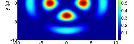
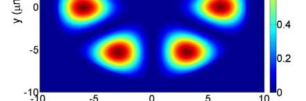
27 Examples of Modes in an Optical Fiber λ µm a µm n.4640 δ


28 Examples of Modes in an Optical Fiber λ µm a µm n.4640 δ
29 Cut-Off Wavelength The propagation constant of a given mode depends on wavelength [β (λ)] The cut-off condition of a mode is defined as β (λ)-k 0 n β (λ)-4π n /λ 0 There exists a wavelength λ c above which only the fundamental mode LP 0 can propagate 0 p p g π V <.405 λc na δ. 84an δ λc λc or equivalently a 0.54 n δ n δ π Example: a 9. µm n.4690 δ0.004 λ c ~. µm 33 33

30 Single-Mode Guidance In a single-mode fiber, for wavelengths λ >λ c ~.6 µm only the LP 0 mode can propagate 34 34
")


31 Mode Field Diameter The fundamental mode of a single-mode fiber is well approximated by a Gaussian function F ( ρ ) Ce ρ w 0 where C is a constant and w the mode size A good approximation for the mode size is obtained from w w a for. < V 3/ 6 V V a for V >. 4 ln( V ) 0 <. 4 Fiber Optics Communication Technology-Mynbaev & Scheiner 35 35
32 Types of Optical Fibers Step-index single-mode n Cladding diameter 5 µm Core diameter from 8 to 0 µm n Refractive index profile n n n δ 0.00 r 36 36
33 Types of Optical Fibers Step-index multimode n Cladding diameter from 5 to 400 µm Core diameter from 50 to 00 µm n Refractive index profile n n n δ 0.0 r 37 37
34 Types of Optical Fibers Graded-index multimode n Cladding diameter from 5 to 40 µm Core diameter from 50 to 00 µm n n Refractive index profile n n r 38 38
35 Attenuation Signal attenuation in optical fibers results form 3 phenomena: Absorption Scattering Bending Loss coefficient: α α depends on wavelength P Out P e in αl P Out 0 0log 0 α L α L P in ln(0) α is usually expressed in units of db/km : α db 4.343α For a single-mode fiber, α db nm 39 39
36 Scattering and Absorption Short wavelength: Rayleigh scattering induced by inhomogeneity of the refractive index and proportional to /λ 4 Absorption Infrared band Ultraviolet band 4 st window nd 3rd 80 nm.3 µm.55 µm IR absorption Rayleigh scattering α /λ 4 Water peaks 0.4 UV absorption 0. 3 Transmission windows 80 nm 300 nm 550 nm Wavelength (µm) 40 40
37 Macrobending Losses Macrodending losses are caused by the bending of fiber Bending of fiber affects the condition θ < θ C For single-mode fiber, bending losses are important for curvature radii < cm 4 4
38 Microbending Losses Microdending losses are caused by the rugosity of fiber Micro-deformation along the fiber axis results in scattering and power loss 4 4
39 Attenuation: Single-mode vs. Multimode Fiber 4 Fundamental mode Higher order mode 0.4 SMF 0. MMF Wavelength (µm) Light in higher-order modes travels longer optical paths Multimode fiber attenuates more than single-mode fiber 43 43
40 Dispersion What is dispersion? Power of a pulse travelling though a fiber is dispersed in time Different spectral components of signal travel at different speeds Results from different phenomena Consequences of dispersion: pulses spread in time t t 3 Types of dispersion: Inter-modal dispersion (in multimode fibers) Intra-modal dispersion (in multimode and single-mode fibers) Polarization mode dispersion (in single-mode fibers) 44 44
41 Dispersion in Multimode Fibers (inter-modal) Input pulse Input pulse Output pulse t t In a multimode fiber, different modes travel at different speed temporal spreading (inter-modal dispersion) Inter-modal dispersion limits the transmission capacity The maximum temporal spreading tolerated is / bit period The limit is usually expressed in terms of bit rate x distance 45 45
42 Dispersion in Multimode Fibers (Inter-modal) Fastest ray guided along the core center Slowest ray is incident at the critical angle n n θ c Slow ray θ L T Fast ray n n n L L c n c n L c T T with T v L L FAST FAST SLOW n n v SLOW FAST L n n T L vfast c n SLOW L cosθ L c δ FAST FAST and T SLOW L π sin cos θ L v SLOW SLOW L sin θ n n C θ L 46 46
43 Dispersion in Multimode Fibers If bit rate B b L n i.e. δ < c n B cn or L B < nδ s We must have T < B Example: n.5and δ 0.0 B L<0Mb s - p Capacity of multimode-step index index fibers B L 0 Mb/s km 47 47
44 Dispersion in graded-index Multimode Fibers Input pulse Input pulse Output pulse t t Fast mode travels a longer physical path Slow mode travels a shorter physical path Temporal spreading is small Capacity of multimode-graded index fibers B L Gb/s km 48 48
45 Intra-modal Dispersion In a medium of index n, a signal pulse travels at the group velocity ν defined as: g dωω λ d β v g dβ πc d λ Intra-modal dispersion results from phenomena Material dispersion (also called chromatic dispersion) Waveguide dispersion Different spectral components of signal travel at different speeds The dispersion parameter D characterizes the temporal pulse broadening T per unit length per unit of spectral bandwidth λ: T D λ L d λ d β DIntra modal in units of ps/nm km dλ vg πc dλ 49 49
46 Material Dispersion Refractive index n depends on the frequency/wavelength of light Speed of light in material is therefore dependent on frequency/wavelength Input pulse, λ t Input pulse, λ t t 50 50
47 Material Dispersion Refractive index of silica as a function of wavelength is given by the Sellmeier Equation A λ Aλ A3λ n( λ) λ λ λ λ λ λ with A A A , λ nm , λ nm , λ 6.44 nm 3 5 5
48 5 Material Dispersion λ λ λ β π λ d dn n c d d c v g / λ λ λ Input pulse, λ λ λ T p p t t L Input pulse, λ t λ λ λ λ λ λ d n d c L v d d L D L T g 5
49 Material Dispersion ps/nm/km m) Material (p Material µ Wavelength (µm) D M -000 DMaterial0@.7 µm λ d n DMaterial (units : ps/nm km) c dλλ 53 53
50 Waveguide Dispersion The size w 0 of a mode depends on the ratio a/λ : λ λ >λ w a / V V 6 Consequence: the relative fraction of power in the core and cladding varies This implies that the group-velocity ν g also depends on a/λ D Waveguide d dλ vg λ π nc d λ d w λ 0 where w 0 is the mode size 54 54
51 Total Dispersion D Intra modal D Material + D Waveguide D Intra-modal <0: normal dispersion region D Intra-modal >0: anomalous dispersion region Waveguide dispersion shifts the wavelength of zero-dispersion to.3 µm 55 55
52 Tuning Dispersion Dispersion can be changed by changing the refractive index Change in index profile affects the waveguide dispersion Total dispersion is changed 0 n n 0 Single-mode Fiber n Single-mode Fiber n Dispersion shifted Fiber 0 Single-mode fiber: 30 nm Dispersion shifted Fiber: 550 nm -0 Dispersion shifted Fiber Wavelength (µm) 56 56
53 57 Dispersion Related Parameters s/km of :group delay in units β β ω β d n c eff y g p modal Intra λ π β λ ω ω β λ β λ β ω c d d d d d d v d d D d v g g /km s group velocity dispersion parameter in units of : β λ λ ω λ λ d d d v d g 57
54 Polarization Mode Dispersion Optical fibers are not perfectly circular y x x In general, a mode has polarizations (degenerescence): x and y Causes broadening of signal pulse T L v gx v gy D Polarization L 58 58
55 Effects of Dispersion: Pulse Spreading Total pulse spreading is determined as the geometric sum of pulse spreading resulting from intra-modal and inter-modal dispersion T T Intermodal + T Intra-modal + T Polarization Multimode Fiber : T Single - Mode Fiber : T ( D L) + ( D λ L) Inter modal ( D λ L) + ( D L ) Intra modal Intra modal Polarization Examples: Consider a LED µm λ50 nm after L km, T5.6 ns D Inter-modal.5 ns/km D Intra-modal 00 ps/nm km Consider a DFB laser µm λ.nmafterl00km, T0.34 ns! D Intra-modal 7 ps/nm km D Polarization 0.5 ps/ km 59 59
56 Effects of Dispersion: Capacity Limitation Capacity limitation: maximum broadening</f a bit period T < B For Single - Md Mode Fiber, T LB < D Intra modal λ LD (neglecting polarization effects) Intra modal λ Example: Consider a DFB laser µm λ 0. nm D 7 ps/nm km LB<50 Gb/s km If L00 km, B Max.5 Gb/s 60 60
57 Advantage of Single-Mode Fibers No intermodal dispersion Lower attenuation No interferences between multiple modes Easier Input/output coupling Single-mode fibers are used in long transmission systems 6 6
58 Summary Attractive characteristics of optical fibers: Low transmission loss Enormous bandwidth Immune to electromagnetic noise Low cost Light weight and small dimensions Strong, flexible material 6 6
59 Summary Important parameters: NA: numerical aperture (angle of acceptance) V: normalized frequency parameter (number of modes) λ c : cut-off wavelength (single-mode guidance) D: dispersion (pulse broadening) Multimode fiber Used in local area networks (LANs) / metropolitan area networks (MANs) Capacity limited by inter-modal dispersion: typically 0 Mb/s x km for step index and Gb/s x km for graded index Single-mode fiber Used for short/long distances Capacity limited by dispersion: typically 50 Gb/s x km 63 63
Optical Fiber Signal Degradation
 Optical Fiber Signal Degradation Effects Pulse Spreading Dispersion (Distortion) Causes the optical pulses to broaden as they travel along a fiber Overlap between neighboring pulses creates errors Resulting
Propagation losses in optical fibers
 Chapter Dielectric Waveguides and Optical Fibers 1-Fev-017 Propagation losses in optical fibers Charles Kao, Nobel Laureate (009) Courtesy of the Chinese University of Hong Kong S.O. Kasap, Optoelectronics
Mode-Field Diameter (MFD)
") Mode-Field Diameter (MFD) Important parameter determined from mode-field distribution of fundamental LP 01 mode. Characterized by various models Main consideration: how to approximate the electric field
Mode-Field Diameter (MFD) Important parameter determined from mode-field distribution of fundamental LP 01 mode. Characterized by various models Main consideration: how to approximate the electric field
Dielectric Waveguides and Optical Fibers. 高錕 Charles Kao
 Dielectric Waveguides and Optical Fibers 高錕 Charles Kao 1 Planar Dielectric Slab Waveguide Symmetric Planar Slab Waveguide n 1 area : core, n 2 area : cladding a light ray can undergo TIR at the n 1 /n
Lect. 15: Optical Fiber
 3-dimentioanl dielectric waveguide? planar waveguide circular waveguide optical fiber Optical Fiber: Circular dielectric waveguide made of silica (SiO ) y y n n 1 n Cladding Core r z Fiber axis SiO :Ge
OPTI510R: Photonics. Khanh Kieu College of Optical Sciences, University of Arizona Meinel building R.626
 OPTI510R: Photonics Khanh Kieu College of Optical Sciences, University of Arizona kkieu@optics.arizona.edu Meinel building R.626 Announcements Homework #4 is assigned, due March 25 th Start discussion
OPTICAL COMMUNICATIONS S
 OPTICAL COMMUNICATIONS S-108.3110 1 Course program 1. Introduction and Optical Fibers 2. Nonlinear Effects in Optical Fibers 3. Fiber-Optic Components I 4. Transmitters and Receivers 5. Fiber-Optic Measurements
Lecture 4 Fiber Optical Communication Lecture 4, Slide 1
 ecture 4 Dispersion in single-mode fibers Material dispersion Waveguide dispersion imitations from dispersion Propagation equations Gaussian pulse broadening Bit-rate limitations Fiber losses Fiber Optical
Photonic Communications Engineering I
 Photonic Communications Engineering I Module 3 - Attenuation in Optical Fibers Alan E. Willner Professor, Dept. of Electrical Engineering - Systems, University of Southern California and Thrust 1 Lead
Lecture 3 Fiber Optical Communication Lecture 3, Slide 1
 Lecture 3 Optical fibers as waveguides Maxwell s equations The wave equation Fiber modes Phase velocity, group velocity Dispersion Fiber Optical Communication Lecture 3, Slide 1 Maxwell s equations in
Nonlinear Effects in Optical Fiber. Dr. Mohammad Faisal Assistant Professor Dept. of EEE, BUET
 Nonlinear Effects in Optical Fiber Dr. Mohammad Faisal Assistant Professor Dept. of EEE, BUET Fiber Nonlinearities The response of any dielectric material to the light becomes nonlinear for intense electromagnetic
OPTICAL COMMUNICATIONS
 L21-1 OPTICAL COMMUNICATIONS Free-Space Propagation: Similar to radiowaves (but more absorption by clouds, haze) Same expressions: antenna gain, effective area, power received Examples: TV controllers,
UNIT 1. By: Ajay Kumar Gautam Asst. Prof. Electronics & Communication Engineering Dev Bhoomi Institute of Technology & Engineering, Dehradun
 UNIT 1 By: Ajay Kumar Gautam Asst. Prof. Electronics & Communication Engineering Dev Bhoomi Institute of Technology & Engineering, Dehradun Syllabus Introduction: Demand of Information Age, Block Diagram
Analysis of Single Mode Step Index Fibres using Finite Element Method. * 1 Courage Mudzingwa, 2 Action Nechibvute,
 Analysis of Single Mode Step Index Fibres using Finite Element Method. * 1 Courage Mudzingwa, 2 Action Nechibvute, 1,2 Physics Department, Midlands State University, P/Bag 9055, Gweru, Zimbabwe Abstract
QUESTION BANK IN PHYSICS
 QUESTION BANK IN PHYSICS LASERS. Name some properties, which make laser light different from ordinary light. () {JUN 5. The output power of a given laser is mw and the emitted wavelength is 630nm. Calculate
LECTURE 23: LIGHT. Propagation of Light Huygen s Principle
 LECTURE 23: LIGHT Propagation of Light Reflection & Refraction Internal Reflection Propagation of Light Huygen s Principle Each point on a primary wavefront serves as the source of spherical secondary
LECTURE 23: LIGHT. Propagation of Light Huygen s Principle
 LECTURE 23: LIGHT Propagation of Light Reflection & Refraction Internal Reflection Propagation of Light Huygen s Principle Each point on a primary wavefront serves as the source of spherical secondary
Optical Fibre Communication Systems
 Optical Fibre Communication Systems Lecture 2: Nature of Light and Light Propagation Professor Z Ghassemlooy Northumbria Communications Laboratory Faculty of Engineering and Environment The University
Optical Spectroscopy of Advanced Materials
 Phys 590B Condensed Matter Physics: Experimental Methods Optical Spectroscopy of Advanced Materials Basic optics, nonlinear and ultrafast optics Jigang Wang Department of Physics, Iowa State University
FIBER OPTICS. Prof. R.K. Shevgaonkar. Department of Electrical Engineering. Indian Institute of Technology, Bombay. Lecture: 07
 FIBER OPTICS Prof. R.K. Shevgaonkar Department of Electrical Engineering Indian Institute of Technology, Bombay Lecture: 07 Analysis of Wave-Model of Light Fiber Optics, Prof. R.K. Shevgaonkar, Dept. of
MIMO and Mode Division Multiplexing in Multimode Fibers
 MIMO and Mode Division Multiplexing in Multimode Fibers Kumar Appaiah Department of Electrical Engineering Indian Institute of Technology Bombay akumar@ee.iitb.ac.in Tutorial: National Conference on Communications
Nonlinear effects in optical fibers - v1. Miguel A. Muriel UPM-ETSIT-MUIT-CFOP
 Nonlinear effects in optical fibers - v1 Miguel A. Muriel UPM-ETSIT-MUIT-CFOP Miguel A. Muriel-015/10-1 Nonlinear effects in optical fibers 1) Introduction ) Causes 3) Parameters 4) Fundamental processes
LOW NONLINEARITY OPTICAL FIBERS FOR BROADBAND AND LONG-DISTANCE COMMUNICATIONS
 LOW NONLINEARITY OPTICAL FIBERS FOR BROADBAND AND LONG-DISTANCE COMMUNICATIONS Haroldo T. Hattori Dissertation submitted to the Faculty of the Virginia Polytechnic Institute and State University in partial
Nonlinear Optical Effects in Fibers
 Nonlinear Optical Effects in Fibers NLO effects are manifested as attenuation, phase shifts, or wavelength conversion effects, and become stronger with increasing light intensity. The glass materials usually
Chapter 24 Photonics Question 1 Question 2 Question 3 Question 4 Question 5
 Chapter 24 Photonics Data throughout this chapter: e = 1.6 10 19 C; h = 6.63 10 34 Js (or 4.14 10 15 ev s); m e = 9.1 10 31 kg; c = 3.0 10 8 m s 1 Question 1 Visible light has a range of photons with wavelengths
Outline. Propagation of Signals in Optical Fiber. Outline. Geometric Approach. Refraction. How do we use this?
 Outline Propagation of Signals in Optial Fiber Geometri approah Wave theory approah Loss and Bandwidth Galen Sasaki University of Hawaii Galen Sasaki University of Hawaii Outline Geometri approah Wave
ECE 484 Semiconductor Lasers
 ECE 484 Semiconductor Lasers Dr. Lukas Chrostowski Department of Electrical and Computer Engineering University of British Columbia January, 2013 Module Learning Objectives: Understand the importance of
Module II: Part B. Optical Fibers: Dispersion
 Module II: Part B Optical Fibers: Dispersion Dispersion We had already seen that that intermodal dispersion can be, eliminated, in principle, using graded-index fibers. We had also seen that single-mode,
1 The formation and analysis of optical waveguides
 1 The formation and analysis of optical waveguides 1.1 Introduction to optical waveguides Optical waveguides are made from material structures that have a core region which has a higher index of refraction
B 2 P 2, which implies that g B should be
 Enhanced Summary of G.P. Agrawal Nonlinear Fiber Optics (3rd ed) Chapter 9 on SBS Stimulated Brillouin scattering is a nonlinear three-wave interaction between a forward-going laser pump beam P, a forward-going
Introduction to optical waveguide modes
 Chap. Introduction to optical waveguide modes PHILIPPE LALANNE (IOGS nd année) Chapter Introduction to optical waveguide modes The optical waveguide is the fundamental element that interconnects the various
Lecture 19 Optical MEMS (1)
") EEL6935 Advanced MEMS (Spring 5) Instructor: Dr. Huikai Xie Lecture 19 Optical MEMS (1) Agenda: Optics Review EEL6935 Advanced MEMS 5 H. Xie 3/8/5 1 Optics Review Nature of Light Reflection and Refraction
EEL6935 Advanced MEMS (Spring 5) Instructor: Dr. Huikai Xie Lecture 19 Optical MEMS (1) Agenda: Optics Review EEL6935 Advanced MEMS 5 H. Xie 3/8/5 1 Optics Review Nature of Light Reflection and Refraction
Step index planar waveguide
 N. Dubreuil S. Lebrun Exam without document Pocket calculator permitted Duration of the exam: 2 hours The exam takes the form of a multiple choice test. Annexes are given at the end of the text. **********************************************************************************
EE485 Introduction to Photonics. Introduction
 EE485 Introduction to Photonics Introduction Nature of Light They could but make the best of it and went around with woebegone faces, sadly complaining that on Mondays, Wednesdays, and Fridays, they must
Fiber designs with significantly reduced nonlinearity for very long distance transmission
 Fiber designs with significantly reduced nonlinearity for very long distance transmission Harold T. Hattori and Ahmad Safaai-Jazi A class of low-nonlinearity dispersion-shifted fibers based on depressed-core
Propagation of signals in optical fibres
 11 11 Fiber optic link OR Propagation of signals in optical fibres??? Simon-Pierre Gorza BEST Course - 213 http://opera.ulb.ac.be/ Outline: 2.1 Geometrical-optics description 2.2 Electromagnetic analysis
L 31 Light and Optics [1] Galileo s result. Galileo and the speed of light. The speed of light inside matter. Measurement of the speed of light
![L 31 Light and Optics [1] Galileo s result. Galileo and the speed of light. The speed of light inside matter. Measurement of the speed of light](/thumbs/74/70673315.jpg "L 31 Light and Optics [1] Galileo s result. Galileo and the speed of light. The speed of light inside matter. Measurement of the speed of light") L 31 Light and Optics [1] Measurements of the speed of light: 186,000 miles per second (1 foot per nanosecond) light propagating through matter transparent vs. opaque materials colors, why is an orange
L 31 Light and Optics [1] Measurements of the speed of light: 186,000 miles per second (1 foot per nanosecond) light propagating through matter transparent vs. opaque materials colors, why is an orange
Si Micro-Ring Resonator. Yoojin Ban
 Si Micro-Ring Resonator Yoojin Ban Why Photonics? Copper wires reaching physical limits ~10 Gbps or higher becoming challenging Distance/speed tradeoff shortens lengths Alternative: Transmit data over
Module 3 - Attenuation in Optical Fibers
 Module 3 - Attenuation in Optical Fibers Dr. B.G. Potter Professor, Material Science and Engineering Dept, University of Arizona Dr. B.G.Potter is a Professor of Material Science and Engineering in the
Numerical Analysis of Low-order Modes in Thermally Diffused Expanded Core (TEC) Fibers
 Fibers") Proceedings of the 4th WSEAS Int. Conference on Electromagnetics, Wireless and Optical Communications, Venice, Italy, November 2-22, 26 26 Numerical Analysis of Low-order Modes in Thermally Diffused Expanded
Proceedings of the 4th WSEAS Int. Conference on Electromagnetics, Wireless and Optical Communications, Venice, Italy, November 2-22, 26 26 Numerical Analysis of Low-order Modes in Thermally Diffused Expanded
Traceable Encircled Flux measurements for multimode fibre components and systems
 Traceable Encircled Flux measurements for multimode fibre components and systems J. Morel / N.Castagna CCPR WG-SP Workshop / 19.09.2016 Outline 1. Introduction to the problematic of multimode fibres 2.
Demonstration of ultra-flattened dispersion in photonic crystal fibers
 Demonstration of ultra-flattened dispersion in photonic crystal fibers W.H. Reeves, J.C. Knight, and P.St.J. Russell Optoelectronics Group, School of Physics, University of Bath, Claverton Down, Bath,
Skoog Chapter 6 Introduction to Spectrometric Methods
 Skoog Chapter 6 Introduction to Spectrometric Methods General Properties of Electromagnetic Radiation (EM) Wave Properties of EM Quantum Mechanical Properties of EM Quantitative Aspects of Spectrochemical
Lasers and Electro-optics
 Lasers and Electro-optics Second Edition CHRISTOPHER C. DAVIS University of Maryland III ^0 CAMBRIDGE UNIVERSITY PRESS Preface to the Second Edition page xv 1 Electromagnetic waves, light, and lasers 1
ANALYSIS AND DESIGN OF SINGLE-MODE FIBER WITH ZERO POLARIZATION-MODE DISPERSION
 CHAPTER 4. ANALYSIS AND DESIGN OF SINGLE-MODE FIBER WITH ZERO POLARIZATION-MODE DISPERSION Polarization-mode dispersion (PMD) has gained considerable attention over the past few years. It has been the
STUDY OF DISPERSION CURVES IN M-TYPE TRIPLE CLAD SINGLE MODE OPTICAL FIBER
 INTERNATIONAL JOURNAL OF ELECTRONICS AND COMMUNICATION ENGINEERING & TECHNOLOGY (IJECET) International Journal of Electronics and Communication Engineering & Technology (IJECET) ISSN ISSN 0976 6464(Print)
9 Atomic Coherence in Three-Level Atoms
 9 Atomic Coherence in Three-Level Atoms 9.1 Coherent trapping - dark states In multi-level systems coherent superpositions between different states (atomic coherence) may lead to dramatic changes of light
4. Integrated Photonics. (or optoelectronics on a flatland)
") 4. Integrated Photonics (or optoelectronics on a flatland) 1 x Benefits of integration in Electronics: Are we experiencing a similar transformation in Photonics? Mach-Zehnder modulator made from Indium
4. Integrated Photonics (or optoelectronics on a flatland) 1 x Benefits of integration in Electronics: Are we experiencing a similar transformation in Photonics? Mach-Zehnder modulator made from Indium
Principle of photonic crystal fibers
 Principle of photonic crystal fibers Jan Sporik 1, Miloslav Filka 1, Vladimír Tejkal 1, Pavel Reichert 1 1 Fakulta elektrotechniky a komunikačních technologií VUT v Brně Email: {xspori1, filka, xtejka,
Estimation of Optical Link Length for Multi Haul Applications
 Estimation of Optical Link Length for Multi Haul Applications M V Raghavendra 1, P L H Vara Prasad 2 Research Scholar Department of Instrument Technology 1, Professor & Chairman (BOS) Department of Instrument
Optics and Optical Design. Chapter 5: Electromagnetic Optics. Lectures 9 & 10
 Optics and Optical Design Chapter 5: Electromagnetic Optics Lectures 9 & 1 Cord Arnold / Anne L Huillier Electromagnetic waves in dielectric media EM optics compared to simpler theories Electromagnetic
INTRODUCTION TO MICROWAVE REMOTE SENSING. Dr. A. Bhattacharya
 1 INTRODUCTION TO MICROWAVE REMOTE SENSING Dr. A. Bhattacharya Why Microwaves? More difficult than with optical imaging because the technology is more complicated and the image data recorded is more varied.
37. 3rd order nonlinearities
 37. 3rd order nonlinearities Characterizing 3rd order effects The nonlinear refractive index Self-lensing Self-phase modulation Solitons When the whole idea of χ (n) fails Attosecond pulses! χ () : New
Optical fibers. Weak guidance approximation in cylindrical waveguides
 Optical fibers Weak guidance approximation in cylindrical waveguides Propagation equation with symmetry of revolution r With cylindrical coordinates : r ( r,θ) 1 ψ( r,θ) 1 ψ( r,θ) ψ + + r r + r θ [ ( )
Optical Fiber. Chapter 1. n 1 n 2 n 2. index. index
 Chapter 1 Optical Fiber An optical ber consists of cylindrical dielectric material surrounded by another cylindrical dielectric material with a lower index of refraction. Figure 1.1 shows that the transistion
Fundamentals of fiber waveguide modes
 SMR 189 - Winter College on Fibre Optics, Fibre Lasers and Sensors 1-3 February 007 Fundamentals of fiber waveguide modes (second part) K. Thyagarajan Physics Department IIT Delhi New Delhi, India Fundamentals
ANTENNA AND WAVE PROPAGATION
 ANTENNA AND WAVE PROPAGATION Electromagnetic Waves and Their Propagation Through the Atmosphere ELECTRIC FIELD An Electric field exists in the presence of a charged body ELECTRIC FIELD INTENSITY (E) A
Nonlinear Optics (NLO)
") Nonlinear Optics (NLO) (Manual in Progress) Most of the experiments performed during this course are perfectly described by the principles of linear optics. This assumes that interacting optical beams
Nonlinear Optics (NLO) (Manual in Progress) Most of the experiments performed during this course are perfectly described by the principles of linear optics. This assumes that interacting optical beams
37. 3rd order nonlinearities
 37. 3rd order nonlinearities Characterizing 3rd order effects The nonlinear refractive index Self-lensing Self-phase modulation Solitons When the whole idea of χ (n) fails Attosecond pulses! χ () : New
Optical Fibres - Dispersion Part 1
 ECE 455 Lecture 05 1 Otical Fibres - Disersion Part 1 Stavros Iezekiel Deartment of Electrical and Comuter Engineering University of Cyrus HMY 445 Lecture 05 Fall Semester 016 ECE 455 Lecture 05 Otical
Electromagnetic fields and waves
 Electromagnetic fields and waves Maxwell s rainbow Outline Maxwell s equations Plane waves Pulses and group velocity Polarization of light Transmission and reflection at an interface Macroscopic Maxwell
Wave Phenomena Physics 15c. Lecture 15 Reflection and Refraction
 Wave Phenomena Physics 15c Lecture 15 Reflection and Refraction What We (OK, Brian) Did Last Time Discussed EM waves in vacuum and in matter Maxwell s equations Wave equation Plane waves E t = c E B t
Electromagnetic Waves
 Electromagnetic Waves Maxwell s equations predict the propagation of electromagnetic energy away from time-varying sources (current and charge) in the form of waves. Consider a linear, homogeneous, isotropic
Dispersion Properties of Photonic Crystal Fiber with Four cusped Hypocycloidal Air Holes in Cladding
 IOSR Journal of Electronics and Communication Engineering (IOSR-JECE) e-issn: 78-834,p- ISSN: 78-8735.Volume 1, Issue 1, Ver. III (Jan.-Feb. 17), PP 35-39 www.iosrjournals.org Dispersion Properties of
GUIDED MICROWAVES AND OPTICAL WAVES
 Chapter 1 GUIDED MICROWAVES AND OPTICAL WAVES 1.1 Introduction In communication engineering, the carrier frequency has been steadily increasing for the obvious reason that a carrier wave with a higher
Lecture 16 Light transmission and optical detectors
 Lecture 6 Light transmission and optical detectors Charged particle traversing through a material can generate signal in form of light via electromagnetic interactions with orbital electrons of the atoms
Theory of optical pulse propagation, dispersive and nonlinear effects, pulse compression, solitons in optical fibers
 Theory of optical pulse propagation, dispersive and nonlinear effects, pulse compression, solitons in optical fibers General pulse propagation equation Optical pulse propagation just as any other optical
Technique for the electric and magnetic parameter measurement of powdered materials
 Computational Methods and Experimental Measurements XIV 41 Technique for the electric and magnetic parameter measurement of powdered materials R. Kubacki,. Nowosielski & R. Przesmycki Faculty of Electronics,
4. The interaction of light with matter
 4. The interaction of light with matter The propagation of light through chemical materials is described by a wave equation similar to the one that describes light travel in a vacuum (free space). Again,
Finite Element Method
 Appendix A Finite Element Method A.1 Formulation All the analyses of the PCF properties presented in this book have been performed by using the FEM. The FEM allows the PCF cross-section in the transverse
10 (4π 10 7 ) 2σ 2( = (1 + j)(.0104) = = j.0001 η c + η j.0104
 2σ 2( = (1 + j)(.0104) = = j.0001 η c + η j.0104") CHAPTER 1 1.1. A uniform plane wave in air, E + x1 E+ x10 cos(1010 t βz)v/m, is normally-incident on a copper surface at z 0. What percentage of the incident power density is transmitted into the copper?
CHAPTER 1 1.1. A uniform plane wave in air, E + x1 E+ x10 cos(1010 t βz)v/m, is normally-incident on a copper surface at z 0. What percentage of the incident power density is transmitted into the copper?
Department of Electrical and Computer Systems Engineering
 Department of Electrical and Computer Systems Engineering Technical Report MECSE-3-4 MODELLING OF POLRISTION MODE DISPERSION EFFECT SYSTEM USING FINITE IMPULSE RESPONSE DICRETE FILTE TECHNIQUE LN Binh
Module 5 - Dispersion and Dispersion Mitigation
 Module 5 - Dispersion and Dispersion Mitigation Dr. Masud Mansuripur Chair of Optical Data Storage, University of Arizona Dr. Masud Mansuripur is the Chair of Optical Data Storage and Professor of Optical
The Electromagnetic Properties of Materials
 The Electromagnetic Properties of Materials Electrical conduction Metals Semiconductors Insulators (dielectrics) Superconductors Magnetic materials Ferromagnetic materials Others Photonic Materials (optical)
Polarization Mode Dispersion
 Unit-7: Polarization Mode Dispersion https://sites.google.com/a/faculty.muet.edu.pk/abdullatif Department of Telecommunication, MUET UET Jamshoro 1 Goos Hänchen Shift The Goos-Hänchen effect is a phenomenon
Summary of Beam Optics
 Summary of Beam Optics Gaussian beams, waves with limited spatial extension perpendicular to propagation direction, Gaussian beam is solution of paraxial Helmholtz equation, Gaussian beam has parabolic
Signal Loss. A1 A L[Neper] = ln or L[dB] = 20log 1. Proportional loss of signal amplitude with increasing propagation distance: = α d
![Signal Loss. A1 A L[Neper] = ln or L[dB] = 20log 1. Proportional loss of signal amplitude with increasing propagation distance: = α d](/thumbs/89/98517557.jpg "Signal Loss. A1 A L[Neper] = ln or L[dB] = 20log 1. Proportional loss of signal amplitude with increasing propagation distance: = α d") Part 6 ATTENUATION Signal Loss Loss of signal amplitude: A1 A L[Neper] = ln or L[dB] = 0log 1 A A A 1 is the amplitude without loss A is the amplitude with loss Proportional loss of signal amplitude with
Part 6 ATTENUATION Signal Loss Loss of signal amplitude: A1 A L[Neper] = ln or L[dB] = 0log 1 A A A 1 is the amplitude without loss A is the amplitude with loss Proportional loss of signal amplitude with
FINITE-DIFFERENCE FREQUENCY-DOMAIN ANALYSIS OF NOVEL PHOTONIC
 FINITE-DIFFERENCE FREQUENCY-DOMAIN ANALYSIS OF NOVEL PHOTONIC WAVEGUIDES Chin-ping Yu (1) and Hung-chun Chang (2) (1) Graduate Institute of Electro-Optical Engineering, National Taiwan University, Taipei,
Chapter 5. Photonic Crystals, Plasmonics, and Metamaterials
 Chapter 5. Photonic Crystals, Plasmonics, and Metamaterials Reading: Saleh and Teich Chapter 7 Novotny and Hecht Chapter 11 and 12 1. Photonic Crystals Periodic photonic structures 1D 2D 3D Period a ~
Optics.
 Optics www.optics.rochester.edu/classes/opt100/opt100page.html Course outline Light is a Ray (Geometrical Optics) 1. Nature of light 2. Production and measurement of light 3. Geometrical optics 4. Matrix
2. Dispersion in the Planar Waveguide
 Chapt.2_2 Words Dispersion diagram( 色散图 ), modal/intermodal dispersion( 模间色散 ), intermodal coupling( 模间耦合 ), intramodal dispersion( 模内色散 ), penetration depth( 渗透深度 ), mode field distance(mfd, 模场距离 ), 2.
MODE THEORY FOR STEP INDEX MULTI-MODE FIBERS. Evgeny Klavir. Ryerson University Electrical And Computer Engineering
 MODE THEORY FOR STEP INDEX MULTI-MODE FIBERS Evgeny Klavir Ryerson University Electrical And Computer Engineering eklavir@ee.ryerson.ca ABSTRACT Cladding n = n This project consider modal theory for step
Lecture 20 Optical Characterization 2
 Lecture 20 Optical Characterization 2 Schroder: Chapters 2, 7, 10 1/68 Announcements Homework 5/6: Is online now. Due Wednesday May 30th at 10:00am. I will return it the following Wednesday (6 th June).
SEAFLOOR MAPPING MODELLING UNDERWATER PROPAGATION RAY ACOUSTICS
 3 Underwater propagation 3. Ray acoustics 3.. Relevant mathematics We first consider a plane wave as depicted in figure. As shown in the figure wave fronts are planes. The arrow perpendicular to the wave
Advanced Vitreous State The Physical Properties of Glass
 Advanced Vitreous State The Physical Properties of Glass Active Optical Properties of Glass Lecture 21: Nonlinear Optics in Glass-Applications Denise Krol Department of Applied Science University of California,
Lecture 36 Date:
 Lecture 36 Date: 5.04.04 Reflection of Plane Wave at Oblique Incidence (Snells Law, Brewster s Angle, Parallel Polarization, Perpendicular Polarization etc.) Introduction to RF/Microwave Introduction One
Introduction to Electromagnetic Radiation and Radiative Transfer
 Introduction to Electromagnetic Radiation and Radiative Transfer Temperature Dice Results Visible light, infrared (IR), ultraviolet (UV), X-rays, γ-rays, microwaves, and radio are all forms of electromagnetic
3.1 The Plane Mirror Resonator 3.2 The Spherical Mirror Resonator 3.3 Gaussian modes and resonance frequencies 3.4 The Unstable Resonator
 Quantum Electronics Laser Physics Chapter 3 The Optical Resonator 3.1 The Plane Mirror Resonator 3. The Spherical Mirror Resonator 3.3 Gaussian modes and resonance frequencies 3.4 The Unstable Resonator
CHAPTER 9 ELECTROMAGNETIC WAVES
 CHAPTER 9 ELECTROMAGNETIC WAVES Outlines 1. Waves in one dimension 2. Electromagnetic Waves in Vacuum 3. Electromagnetic waves in Matter 4. Absorption and Dispersion 5. Guided Waves 2 Skip 9.1.1 and 9.1.2
Negative epsilon medium based optical fiber for transmission around UV and visible region
 I J C T A, 9(8), 2016, pp. 3581-3587 International Science Press Negative epsilon medium based optical fiber for transmission around UV and visible region R. Yamuna Devi*, D. Shanmuga Sundar** and A. Sivanantha
Nonlinear Fiber Optics and its Applications in Optical Signal Processing
 1/44 Nonlinear Fiber Optics and its Applications in Optical Signal Processing Govind P. Agrawal Institute of Optics University of Rochester Rochester, NY 14627 c 2007 G. P. Agrawal Outline Introduction
2008,, Jan 7 All-Paid US-Japan Winter School on New Functionalities in Glass. Controlling Light with Nonlinear Optical Glasses and Plasmonic Glasses
 2008,, Jan 7 All-Paid US-Japan Winter School on New Functionalities in Glass Photonic Glass Controlling Light with Nonlinear Optical Glasses and Plasmonic Glasses Takumi FUJIWARA Tohoku University Department
Plastic Coated Silica/Silica (Low OH) FIBER CROSS SECTION Polyimide and Acrylate Coated. Nylon and Tefzel Coated
 FIBER CROSS SECTION Polyimide and Acrylate Coated. Nylon and Tefzel Coated") DESCRIPTION When looking for a high quality fiber with superior transmission and a numerical aperture (N.A.) of 0.22 for efficient light coupling, the is the fiber of choice. The Anhydroguide fiber is
DESCRIPTION When looking for a high quality fiber with superior transmission and a numerical aperture (N.A.) of 0.22 for efficient light coupling, the is the fiber of choice. The Anhydroguide fiber is
THz Electron Gun Development. Emilio Nanni 3/30/2016
 THz Electron Gun Development Emilio Nanni 3/30/2016 Outline Motivation Experimental Demonstration of THz Acceleration THz Generation Accelerating Structure and Results Moving Forward Parametric THz Amplifiers
PHOTONIC BANDGAP FIBERS
 UMEÅ UNIVERSITY May 11, 2010 Department of Physics Advanced Materials 7.5 ECTS PHOTONIC BANDGAP FIBERS Daba Dieudonne Diba dabadiba@gmail.com Supervisor: Andreas Sandström Abstract The constant pursuit
Optimization of Hybrid Fiber Amplifiers in uncompensated links designed for NyWDM transmission
 Universidad de Valladolid Final Thesis Optimization of Hybrid Fiber Amplifiers in uncompensated links designed for NyWDM transmission Author: Carlos Gomez Tome Supervisors: Vittorio Curri Andrea Carena
Fresnel Equations cont.
 Lecture 11 Chapter 4 Fresnel quations cont. Total internal reflection and evanescent waves Optical properties of metals Familiar aspects of the interaction of light and matter Fresnel quations: phases
MASSACHUSETTS INSTITUTE OF TECHNOLOGY Department of Electrical Engineering and Computer Science
 Time: March 10, 006, -3:30pm MASSACHUSETTS INSTITUTE OF TECHNOLOGY Department of Electrical Engineering and Computer Science 6.097 (UG) Fundamentals of Photonics 6.974 (G) Quantum Electronics Spring 006
MEFT / Quantum Optics and Lasers. Suggested problems Set 4 Gonçalo Figueira, spring 2015
 MEFT / Quantum Optics and Lasers Suggested problems Set 4 Gonçalo Figueira, spring 05 Note: some problems are taken or adapted from Fundamentals of Photonics, in which case the corresponding number is
Raman Amplification for Telecom Optical Networks. Dominique Bayart Alcatel Lucent Bell Labs France, Research Center of Villarceaux
 Raman Amplification for Telecom Optical Networks Dominique Bayart Alcatel Lucent Bell Labs France, Research Center of Villarceaux Training day www.brighter.eu project Cork, June 20th 2008 Outline of the