S. Eswar Prasad, Adjunct Professor, Department of Mechanical & Industrial Engineering, Chairman, Piemades Inc, Piemades, Inc.
|
|
|
- Emil Shaw
- 5 years ago
- Views:
Transcription
1 Lecture 1: Introduction to Smart Materials and Systems Lecture 2: Sensor technologies for smart systems and their evaluation criteria. Lecture 3: Actuator technologies for smart systems and their evaluation criteria. Lecture 4: Piezoelectric Materials and their Applications. Lecture 5: Control System Technologies. Lecture 6: Smart System Applications. S. Eswar Prasad, Adjunct Professor, Department of Mechanical & Industrial Engineering, Chairman, Piemades Inc, Piemades, Inc. 1
2 Precision sensors for measurement of strain, displacement and acceleration S. Eswar Prasad, Adjunct Professor, Department of Mechanical & Industrial Engineering, Chairman, Piemades Inc, Piemades, Inc. 2
3 Sensors for Smart Systems Sensors? Physical Principles - How they work? Selection of sensors and evaluation criteria Examples 3
4 Need for Sensors Sensors are pervasive. They are embedded in our bodies, automobiles, airplanes, cellular telephones, radios, chemical plants, industrial plants and countless other applications. Without the use of sensors, there would be no automation! 4
5 Sensors for Smart Systems Need for sensors determine the load on the structure forces acting on the body nature of vibrational excitations magnitude of displacements to be controlled 5
6 Sensors - Definition American National Standards Institute A device which provides a usable output in response to a specified measurand. Sensors are devices that produce an output signal for the purpose of sensing a physical phenomenon. Sensors are also referred to as transducers. A transducer is a device that converts a signal from one physical form to a corresponding signal that has a different form. Quantities at the input level are different from the output level. Generally the output is in the form of an electrical signal. Sensors are used for measuring and recording a quantity. The measured quantity can be just recorded or further processed for controlling a system. 6
7 Types of Sensors : Analog, Digital, Active, Passive Analog: Output is continuous, output is a function of input. Requires ADC for interfacing. Digital: The output is in the form of a digital signal. Can be directly connected to a computer. PWM, serial, parallel, etc. Active Sensors:Need separate power source to obtain the output. Passive Sensors: These are self generating in the sense that they produce (electrical) signals when subjected to the sensed quantity. Piezoelectric, thermoelectric, radioactive,... Sensor output is generally in the form of resistance change or voltage change or capacitance change or current change when input quantity is changed. Appropriate circuit is required to measure the above changes. 7
8 Sensors - Basic Characteristics Sensitivity: It is the ability of the measuring instrument to respond to changes in a measured quantity. It is the ratio of change of the output to change of the input. The sensitivity K is defined as the rate of change of the output (O) with respect to the input (I). I Transducer O Energy Source I - input, quantity to be sensed. O - output, signal which can be recorded. Sensitivity = O/ I For a linear sensor: O/ I = k = constant For a non-linear sensor: O/ I = K a1i + a2i 2 + a3i
9 Sensor Characteristics Quality Error & Non-linearity Static and Dynamic Characteristics Types 9

10 Quality of a sensor Resolution: It is defined as the smallest increment in the measured value that can be detected. Resolution is defined as the largest change in I that can occur without a corresponding change in O.! Accuracy: It is a measure of the difference between the measured value and the actual value. Generally, it is defined as percentage of actual value. Precision: Precision is the ability of an instrument to reproduce a certain set of readings within a given deviation. Repeatability: It is the ability to reproduce the output signal exactly when the same measured quantity is applied repeatedly under the same environmental conditions. Bull s Eye Target Plate a. High precision with poor accuracy b. Good average accuracy with poor precision c. High accuracy with high precision d. Poor accuracy with poor precision 10
11 Quality of a Sensor Resolution: It is defined as the smallest increment in the measured value that can be detected. Resolution is defined as the largest change in input (I) that can occur without a corresponding change in output (O).! O IR I 11
12 Quality of a Sensor Range & span: The range of input physical signals which may be converted to electrical signals by the sensor. Signals outside of this range are expected to cause unacceptably large inaccuracy.! Span is maximum value minus the minimum value of the input. Stability (drift)-it is the ability to give the same output when a constant input is measured over a period of time. Drift is expressed as a percentage of full range output. Dead band: It is the range of input values for which there is no output. Backlash: It is defined as the maximum distance or angle through which any part of a mechanical system can be moved in one direction without causing any motion of the attached part. Hysteresis: Different outputs corresponding to a single value of the input. 12
13 Error and Non-Linearity Error: The discrepancy between the instrument reading and the true value is called error. Absolute error = measured value - actual value Relative error = absolute error / true value For many transducers a linear relationship between the input and output is assumed over the working range. Few transducers, however, have a truly linear relationship and thus errors often occur as a result of the assumption of linearity. Various methods are used for the numerical expression of the non- linearity error - End-range values - Best straight line for all values - Best straight line through zero point 13
14 14
15 Non-linearity N(I) = O(I) - OIdeal(I) = O(I) - (KI + a) Maximum Non-linearity Text NMAX% = NMAX x 100 (OMAX - OMIN) 15

16 Error Bands It is often impractical to separate and determine nonlinearity, resolution and other such effects in these cases, non ideal performance is classified by one broad term: the error band Accuracy Generally defined as the largest expected error between actual and ideal output signals. h O(I) = Oideal ± h 16
17 Sensor Characteristics Static characteristics are the values given when steady state conditions occur. Input is not varying and output is constant. Output changes only due to drift. Dynamic characteristics refer to time varying signal with corresponding time varying output. Response time: time which elapses after a step input, when the sensor reaches the output corresponding to some specified percentage of its steady state value e.g. 95%. Time constant: This is 63.2 % of the response time. Rise time: Time taken for the output to rise to some specified percentage of the steady state output. From 10% to 90%. Settling time: This is the time taken for the output to settle to within some percentage e.g. 2% of steady state value. 17
18 Sensors for Smart Systems Smart System response can fall into five categories - mechanical, electrical, magnetic, thermal or chemical. Electrical response is the easiest to monitor and analyze. Discuss types of sensors - that measure mechanical response and temperature. Scope is limited to a few types of sensors for each type. 18
19 Commonly Detectable Phenomena Temperature Mechanical motion(displacement, velocity, acceleration, etc.) Optical Electrical Chemical Electromagnetic Biological Radioactivity 19
20 Examples of Physical Principles Used Amperes s Law A current carrying conductor in a magnetic field experiences a force (e.g. galvanometer) Curie-Weiss Law There is a transition temperature at which ferromagnetic materials exhibit paramagnetic behaviour Faraday s Law of Induction A coil resist a change in magnetic field by generating an opposing voltage/current (e.g. transformer) Photoconductive Effect When light strikes certain semiconductor materials, the resistance of the material decreases (e.g. photoresistor) 20
21 Sensor Principles Parameter Sensor Principle Displacement Potentiometer LVDT Capacitance Change of Resistance Electromagnetic Induction Variation of Capacitance Strain Strain Gage Piezoelectric Fibre Optics Change of Resistance Generator of Voltage Interferometers 21
22 Sensor Principles Parameter Sensor Principle Force and Acceleration Load Cells Piezoelectric Change of Resistance Generation of Voltage Temperature Thermistors Thermocouples Fibre Optics Change of Resistance Generator of Voltage Interferometers 22
23 Sensors for Smart Systems Displacement (proximity) Strain Force and Acceleration Temperature (Flowmeters not discussed in this lecture) 23
24 Displacement Sensors Resistive Potentiometers Inductive: Linear Variable Differential Transformer Proximity Sensors Non-contact Encoders Capacitive Sensors 24
25 Displacement (Proximity) Sensors - Potentiometers Potentiometers are variable resistance sensors. A wiper contact is linked to a mechanical shaft. Linear or rotational movement. Output is proportional to resistance and thence the position. 25
26 26
")

27 Displacement (Proximity) Sensors - Potentiometers 27
28 28
29 29
30 30

31 Displacement (Proximity) Sensors - Potentiometers Celesco 31
32 Displacement (Proximity) Sensors - Linear Variable Differential Transformer Popularly known as LVDT No mechanical wear Very accurate Linear output Expensive compared to potentiometers 32
 Sensors")

33 Displacement (Proximity) Sensors - Linear Variable Differential Transformer 33

34 Primary excitation Secondary 1 Secondary 2 Secondary 1 - Secondary

35 Displacement (Proximity) Sensors - Linear Variable Differential Transformer Schaevitz 35
36 Non-contact Sensors - Inductive (Proximity) Sensors Detection of metallic objects in front of the sensors without physical contact. Useful in wet and dirty environments. Small range. Used in traffic signals, bicycle computers, exercise machines etc. 36

")
37 Non-contact Sensors - Inductive (Proximity) Sensors 37
38 Non-contact Sensors - Rotary Encoders Generates square pulses using photo or infra red cell arrangement. Convert mechanical movement into electrical signal. High resolution. Used in computer hard drives, CD/DVD etc. 38


39 Non-contact Sensors - Rotary Encoders Output! = 360/n where n is the number of segments on coded disc. 39
40 Non-contact Sensors - Capacitive Sensors Measure the change in capacitance. Convert mechanical movement into electrical signal. High precision. Metrology, multi-axis measurements, out of plane measurements. 40

41 ext 41
42 42
43 43

44 Non-contact Sensors - Capacitive Sensors Capacitance Area x Dielectric Constant Distance 44
45 45

46 46
47 47
48 Sensors for Smart Systems Displacement (proximity) Strain Force and Acceleration Temperature 48
49 Strain Sensors Silicon Strain Gauges Piezoelectric Strain Gauges. Fibre-optic Strain gauges. 49

50 Strain Sensors Basic definitions 50
51 Strain Sensors Strain gages convert mechanical motion into electrical signal. A change in resistance, inductance or capacitance is proportional to the strain induced. Strain can be bending, torsional or poisson. 51
 The strain Gage has a finite size and thus a measurement reflects an average of strain over a small area.")
52 Measurements Using Strain Gauge Elements Stress Force (by measuring the strain of a flexural element) Position Pressure (by measuring strain in a flexible diaphragm) Temperature (by measuring thermal expansion of a material) The strain Gage has a finite size and thus a measurement reflects an average of strain over a small area. 52
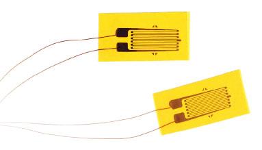
53 Strain Sensors The metallic foil-type strain gage consists of a grid of wire filament bonded directly to the strained surface by a thin layer of epoxy resin. When a load is applied to the surface, the electrical resistance of the foil wire varies linearly with strain. The adhesive also serves as an electrical insulator between the foil grid and the surface. 53


54 Strain Gages 54

55 55
56 Strain Gages are generally mounted on cantilevers and diaphragms and measure the direction of these. More than one strain gage is generally used and the readout generally employs a bridge circuit. 56
57 Strain Sensors Bending Strain (also known as moment strain) is based on bending produced by the applied force. Shear Strain is based on the angular distortion produced. Torsional strain is the ratio of torsional stress to the torsional modulus of elasticity. Poisson strain is defined as the negative ratio of the strain in the transverse direction to the strain in the longitudinal direction. 57
58 Basic Principle of Measurement The resistance of the foil changes when deformed. The connected metal foil grid lines in the active portion of the gage can be approximated by a single rectangular conductor. A is the cross sectional area; A = W x h ρ is the foil metal resistivity Total resistance R is given by R= ρ. L / A [1] 58
59 Basic Principle of Measurement The gage end loops and the solder tabs have a much larger cross-section tan the foil lines and thus have a smaller effect on the gage resistance. [1] ln R = ln ρ + ln L - ln A [2] Taking the differential dr = dρ + dl - da [3]! R ρ L A but A = W. h da = W dh + h DW A w h da = dh + A h dw W 59
60 Principle of Measurement - continued. Poisson s Ratio ν = -ε transverse ε axial and for most materials ν! 0.3 ε axial = dl/l ε 1 transverse = dh/h ε 2 transverse = dw/w dh/h = ν dl/l [5] dw/w = - ν dl/l [6] [4] da/a = -2 ν dl/l = -2 ν ε axial [7] 60
61 Principle of Measurement - continued. when the conductor is elongated, ε axial > 0 and T=thus based on [7] da/a < 0 and R increases. [3] dr/r = dρ/ρ + ε axial (1 =2 ν) dr/r = (1 + 2ν)ε axial + d ρ/ρ dr/r = 1+ 2ν + dl/l ε [8] axial ε axial The last term is the effect of strain on resistivity of material (piezoresistive efffect) and is typically constant over operating range of typical strain gage metal foils 61
62 Principle of Measurement - continued. Gage Factor G = (1 + 2ν) + dl/l εaxial So dr/r = G εaxial relates to change in resistance to strain. [9] The strain is determined on the surface of the loaded component in the Z direction of the gage long axis. G is typically 2 for metal wires or foil. It can be much larger for semiconductor wires. So in order to measure strain, the resistance change needs to be measured and is based on knowing R and G in advance,. The changes in resistance are measured using a Wheatstone Bridge. 62
63 Principle of Measurement - continued. There are two modes of operation of a Wheatstone Bridge. 1. Static Balanced Mode (used initially to balance the bridge) 2. Dynamic unbalanced mode(used to measure changes in resistance) Vi is the input voltage to the bridge and VAB Voltmeter with high input impedance R1: Strain gage (measure the change in resistance) R3: Precision potentiometer R2 and R4 are precision resistors i3 i2 i4 63
64 Principle of Measurement - continued. i2 i2 i3 i4 i4 Step1: Balance the bridge by changing R3 until the Voltage VAB is zero. Step 2: When the bridge is in balanced state, i1r1 = i3r3 [10] Assuming the current going through the voltmeter is essentially zero, then, i1 = i2 = Vi/(R1+R2) [11] i3 = i4 = Vi/(R3+R4) [12] 64
65 Static Balanced Mode - continued [10] Vin. R1 = R1+R2 Vin R3+R4. R3! R1 = R1+R2! R3 R3+R4! R1(R3+R4) = R3(R1+R2)! R1R4 = R3R2! R1 = R2R3/R4 [13] So R1 can be determined based on the known values of R2, R3 and R4 such that the bridge is balanced. 65
66 Static Balanced Mode - continued It is important to note that R1 is independent of input voltage Vin. The static balanced mode of operation can be used to measure an unknown resistance but usually balancing is used only as a preliminary step to measure changes in resistance. Changes in resistance are measured using the dynamic deflection operation mode. 66
67 Dynamic Deflection Operation Amplifier must be high input impedance type (e.g. instrumentation amplifier with a gain of 1) R 1 represents the strain gage R 4 - potentiometer V 0 = (V in - R 2 i 2 ) - (V in - R 1 i 1 ) [14] Vin = (R 2 + R 3 ) i 2 = (R 1 + R 4 ) i 1 [15] [14] V 0 = - R 2 V in + R 1 V in R 2 +R 3 R 1 +R 4 V 0 = V in ( R 1 - R 2 ) [16] R 1 +R 4 R 2 +R 4 Note that when the bridge is balanced, R 1 = R 2 R 4 /R 3 or R 1 (R 2 +R 3 ) = R 2 (R 1 +R 4 ) So when the bridge is balance, V 0 = 0 and R 1 has a known value. 67
68 Dynamic Deflection Operation When R1 changes value, the bridge is not balanced and the earlier equation cannot be used to relate changes in output voltage ( V0) to the change in resistance ( R1). 0 [16]!! V0 + V0 = Vin ( R1 + R1 - R2 )!!!! [17]!!! R1 + R1 + R4 R2 + R3 V0 = 0 since this is a deviation from the balanced mode. [17]!! V0 = R1 + R1 - R2!! Vin R1 + R1 + R4 R2 + R3!! ( V0 + R2 ) ( R1 + R1 + R4 ) = R1 + R1!! Vin R2 + R3!! R1 ( V0 + R2-1) = R1 - (R1 + R4 ) ( V0 + R2 )!!! Vin R2 + R3!!!! Vin R2 + R3! 68
69 Dynamic Deflection Operation! R1 = 1 - ( 1 + R4/R1) { ( V0/Vin) + (R2/R2+R3)} R1! V0/Vin + (R2/R2+R3) -1! R1 = {1 - ( V0/Vin) - (R2/R2+R3) } - ( R4/R1) { ( V0/Vin) + (R2/R2+R3)} R1! V0/Vin + (R2/R2+R3) -1! R1 = (R4/R1) { ( V0/Vin )+ (R2/R2+R3) } - 1" " " " [18] R1" 1- V0/Vin - (R2/R2+R3) By measuring the V0, we can estimate R, and therefore, get an estimate of the axial strain axial = ( R1/R)/G 69
70 R R+ R Strain gage R R - R For balanced mode V0 = (Vin - R i2) - (Vin - (R+ R) i1) V0 = R i1 - R i2 + R i1 Vin = 2 R i2 = (R+ R) i1 + (R- R) i1 = 2 R i1 V0 = R i1 = Vin. R!!! 2 R If we use four active gages placed such that R- R R+ R It can be shown that V0 Vin. ( R/R) which leads to improved sensitivity of the bridge. R+ RR R - R R 70
71 An example of a displacement sensor strain gage cantilever-type load transducer Voltage from balanced position is given by V0 = Vin ( R+ R1 - R2 )! R+ R1+R4 R2+R3 Neutral Axis If R1 = R2 = R3 = R4 = R R1 = R and R << R from balanced mode V0 = Vin ( R+ R - R )! 2R+ R1 2R R2 R1+ R1 V0 = Vin. R + 2 R - (R + R)! 2(2R+ R ) R3 R R4 V0 = Vin R = Vin. R 2 2R+ R 4 R Gage1 Suppose now the bridge involves two active gages, then the gages are subject to equal but opposite strain. Neutral Axis Gage2 71
72 The Strain Gage Load Cell When the cylinder is compressed - 2 strain gages are in compression - 2 strain gages are subject to tensile loading This produces a signal enhancement factor of 2 ( 1+ν) where ν is the Poisson s ratio. 72
73 73

74 Strain Sensors Text Omega Engineering Strain gage installation methods 74
75 Dynamic Deflection Operations (Effect of wire leads) R1 is the strain gage. Bridge is balanced: V0 = 0 R1 = R2 R1+R4 R2+R3 R1 changes (R1 + R1) : R4 ( V0 + R2 ) - 1 R1 Vin R2+R3 R1 = R1 1 - V0 - R2 Vin R2+R3 εaxial = R1/R1 G 75
76 2-wire connection Two wire connection makes bridge sensitive to variations in load resistance RL. This circuit is not expected to work well. V0 represents changes in R1 and the 2 RLs. 76
77 3-wire connection R R2 R1 R R3 R4 V0 = Vin ( R1 - R2 ) R = 0 R1+R4 R2+R3 V0 = Vin ( R1+R / - R2 ) (R1+ R / ) + (R4+R / ) R2+R3 R1 = R1+R / R1+R4 (R1+ R / ) + (R4+R / ) R4 = R1 V0 = Vin ( 1 - R2 )!!!!! 2 R2+R3 When R1 is a constant and R1 = R4, the addition of the three wire connection has no effect on the bridge. 77
78 What is the effect of the addition of R / on the bridge if R1 varies and becomes R1 + R1? 0 V0 + V0 = V0 = Vin ( R1 + R1+R / - R2 ) (R1+ R1+R4+2R / ) R2+R3 V0 = R1 + R1+R / - R2 Vin (R1+ R1+R4+2R / ) R2+R3 ( V0 + R2 ) = R1 + R1+R / Vin R2+R3 (R1+ R1+R4+2R / ) (R1+R4+2R / ) ( V0 + R2 ) - ( R1 +R / ) = R1 ( 1 - V0 - R2 ) R1 = When R1 = R4 R1 = Vin R2+R3 Vin R2+R3 (R1+R4+2R / ) ( V0 + R2 ) - ( R1 +R / ) Vin R2+R3 ( 1 - V0 - R2 ) Vin R2+R3 (R1+R / ) [ 2( V0 + R2 ) - 1 ] Vin R2+R3 ( 1 - V0 - R2 ) Vin R2+R3 So even for R1 = R4, R / remains in the R1 expression. Therefore R / effects the bridge measurements. R1 is selected so that it does not exceed 0.1% of the nominal gage resistance. 78
79 Effect of Temperature Temperature changes in the actual strain gage can cause large changes in resistance which would lead to errors in the measurements. To be bonded Vin To overcome this, a half-bridge circuit is used where two of the four bridge legs contain identical strain gages. The dummy gage is made of unstressed material of the same composition and at the same temperature and is identical to the active gage. The resistance changes in the two gages due to temperature will cancel since they are adjacent branches of the bridge circuit. The bridge will generate an unbalanced voltage only in response to a strain in the active gage. 79
80 Sensors for Smart Systems Displacement (proximity) Strain Force and Acceleration Temperature 80
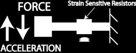
81 Force and Acceleration Sensors The operating principles force and acceleration are very similar and most often the specifics of configuration determine the output. 81
82 Force and Acceleration Sensors What is an accelerometer? A sensor that measures acceleration based on Newton s second law of motion The acceleration of an object as produced by a net force is directly proportional to the magnitude of the net force, in the same direction as the net force, and inversely proportional to the mass of the object. or, mathematically, F = m a 82

83 Force and Acceleration Sensors Trossen Robotics 83


84 Force and Acceleration Sensors 84
85 Force and Acceleration Sensors - Piezoelectrics Piezoelectric elements are bi-directional transducers capable of converting stress into an electric potential and vice versa. They consist of metallized quartz or ceramic materials. One important factor to remember is that this is a dynamic effect, providing an output only when the input is changing. This means that these sensors can be used only for varying pressures 85

86 Omega Force and Acceleration Sensors - Piezoelectrics 86
87 Sensors for Smart Systems Displacement (proximity) Strain Force and Acceleration Temperature 87
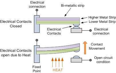
88 Temperature Measurement Bimetallic Strips Fluid Expansion Devices Change-of-State Temperature Measurement Thermocouples (TCs) Resistance Temperature Devices (RTDs) Infrared Devices 88
89 Temperature Measurement - Bimetallic Strips Two sheets of metals, usually brass and steel or their alloys, with different coefficients of thermal expansion are bonded together. The resulting bimetallic strip bends when heated. This phenomenon has many applications, including thermal switches and thermometers. 89


90 Temperature Measurement - Bimetallic Strips 90


91 Temperature Measurement - Bimetallic Strips 91

92 Temperature Measurement - Fluid Expansion Devices Fluid-expansion devices, typified by the household thermometer, generally come in two main classifications: the mercury type and the organic-liquid type. Other types may also contain gas instead of liquid. Fluid-expansion sensors do not require electric power, do not pose explosion hazards, and are stable after repeated cycling. They do not generate data that are easily recorded or transmitted, and they cannot make spot or point measurements. 92
93 Temperature Measurement - Change-of-State Measurement Devices Change-of-state temperature sensors form a broad category of sensors consisting of labels, pellets, crayons, lacquers or liquid crystals. The appearance of the surface of these devices changes once a certain temperature is reached. Typical applications are traps - when a trap exceeds a certain temperature, a white dot on a sensor label attached to the trap will turn black. 93

94 Temperature Measurement - Change-of-State Measurement Devices Response time typically takes minutes, so these devices often do not respond to transient temperature changes. Accuracy is lower than with other types of sensors. The change in state is irreversible in most cases. Change-of-state sensors can be handy when one needs confirmation that the temperature of a piece of equipment or a material has not exceeded a certain level, for instance for technical or legal reasons during product shipment. 94
95 Temperature Measurement - Thermocouples A thermocouple is a sensor for measuring temperature. It consists of two dissimilar metals, joined together at one end. When the junction of the two metals is heated or cooled a voltage is produced that can be correlated back to the temperature. The thermocouple alloys are commonly available as wire. 95
96 Temperature Measurement - Thermocouples The thermoelectric voltage is known as the Seebeck voltage, named after Thomas Seebeck, who discovered it in The voltage is nonlinear with respect to temperature (but for small changes in temperature it is approximately linear) The voltage is given by V S T!(1) where V is the change in voltage, S is the Seebeck coefficient, and T is the change in temperature. 96
97 Temperature Measurement - Thermocouples Several standard types that are given designations according to the materials used. These thermocouples use a variety of different materials. The ones used in the thermocouples mentioned above are all forms of metal alloys: Alumel! Nickel 96%, manganese 2%, aluminum 2% Chromel Nickel 90%, chrome 10% Constantan! Copper 55%, nickel 45% Nicrosil! Nickel chrome silicon Nisil! Nickel silicon 97
98 Temperature Measurement - Thermocouples 98
99 Temperature Measurement - Thermocouples 99
100 Temperature Measurement - Thermocouples Cold-Junction Compensation in Thermocouples Thermocouples require some form of temperature reference to compensate for room temperature. The term cold junction comes from the traditional practice of holding this reference junction at 0 C in an ice bath. The National Institute of Standards and Technology (NIST) thermocouple reference tables are created with this in view. David Potter, National instruments 100

101 Temperature Measurement - Thermocouple Colour Codes 101
102 Temperature Measurement - Resistance Temperature Detectors (RTDs) A resistance-temperature detector (RTD) is a temperature sensing device whose resistance increases with temperature. An RTD consists of a wire coil or deposited film of pure metal. RTDs can be made of different metals and have different resistances, but the most popular RTD is platinum and has a nominal resistance of 100 Ω at 0 C. 102
103 Temperature Measurement - Resistance Temperature Detectors (RTDs) Why RTDs? RTDs are known for their excellent accuracy over a wide temperature range. RTDs have accuracies as high as 0.01 Ω (0.026 C) at 0 C. RTDs are also extremely stable devices. Common industrial RTDs drift less than 0.1 C/year, and some models are stable to within C/year. 103

104 Temperature Measurement - Resistance Temperature Detectors (RTDs) R t = R 0 * (1 + A* t + B*t 2 + C*(t-100)* t 3 ) Where: R t is the resistance at temperature t, R 0 is the resistance at 0 C, and A= E-3 o C -1 B = E-7 o C -2 C = E C -4 (below 0 C), or C = 0 (above 0 C) 104
105 Temperature Measurement - Non-contact Measurement Fibre optic thermometers have proven invaluable in non-contact measurement of temperatures, particularly in harsh conditions, such as high temperatures, large electric and magnetic fields etc. Typical applications are: Basic metals and glass production and initial hot forming processes for such materials. Boiler burner flames and tube temperatures Critical turbine areas in power generation operations Rolling lines in steel and other fabricated metal plants Automated welding, brazing and annealing equipment Fusion, sputtering, and crystal growth processes in the semiconductor industry. 105
106 Temperature Measurement - Non-contact Measurement Fibre-optic sensors can be used to detect heat or stress. Two types of fibre-optic sensors are used, intrinsic and extrinsic types. In the extrinsic type, fibre acts as a medium of transmission. The light exits and interacts with the environment to be analyzed and then re-enters the fibre. This is a low cost method and can use photodiodes for the operation. In the intrinsic type, one or more field parameters become modulated with the field which propagates in the fibre to allow the measurement of environmental effects. Generally these techniques involve interferometric methods and can detect both strain and temperature fluctuations. 106
107 Temperature Measurement - Non-contact Measurement Text The Mach Zehnder interferometer is a device used to determine the relative phase shift between two collimated beams from a coherent light source. It splits an optical signal into two components and directs them down two separate paths, then recombines them. By inducing a phase delay between the two optical signals, the resulting interference can cause intensity changes. 107
108 Temperature Measurement - Non-contact Measurement The Fabry Pérot interferometer makes use of multiple reflections between two closely spaced partially silvered surfaces. Part of the light is transmitted each time the light reaches the second surface, resulting in multiple offset beams which can interfere with each other. The large number of interfering rays produces an interferometer with extremely high resolution, somewhat like the multiple slits of a diffraction grating increase its resolution. 108
109 Sensor Evaluation Criteria Sensor Characteristics Environmental Factors Economic Factors Sensitivity Range Precision Resolution Accuracy Offset Linearity Hysteresis Response Time Dynamic Linearity Size Power Consumption Ruggedness Temperature Range Corrosion Sensitivity to humidity Over range Protection Self Test / Self-calibrate Immunity to EM Interference Cost Availability Service Life Joseph Carr, John Brown, Introduction to Biomedical Equipment Technology, National instruments Sookram Sobhan, Introduction to Sensors,
110 Selection of Displacement Sensors Performance Parameter Potentiometer LVDT Sensitivity N/A 110 mv/mm Range 25 mm mm Resolution 0.1 mm N/A 110
111 Selection of Strain Sensors Performance Parameter Strain Gage Piezoelectric Fibre Optics Sensitivity High Moderate Moderate Resolution Moderate Moderate High Range Moderate High High 111
112 Selection of Acceleration Sensors Performance Parameter Load Cell Accelerometer Sensitivity N/A 110 mv/mm Range 50 g ± 50 g Resolution 0.2 fsd g pk 112
113 Selection of Temperature Sensors Performance Parameter Thermocouple J-type K-type RTD Sensitivity 61 mv/ 0 C 40 mv/ 0 C ±0.20C Range C to C C to C C to C Response Time <5 s <5 s 0.5 s 113
114 Intelligent Sensor Systems Compensation Self-diagnostics, self-calibration, adaptation Computation Signal conditioning, data reduction, detection of trigger events Communications Network protocol standardization Integration Coupling of sensing and computation at the chip level n! Micro electromechanical systems (MEMS) Others Multi-modal, multi-dimensional, multi-layer n!active, autonomous sensing 114
115 Revised Thermocouple Reference Tables TYPE J Reference Tables N.I.S.T. Monograph 175 Revised to ITS-90 Extension Grade + Iron vs. Copper-Nickel Thermocouple Grade + MAXIMUM TEMPERATURE RANGE Thermocouple Grade 32 to 1382 F 0 to 750 C Extension Grade 32 to 392 F 0 to 200 C LIMITS OF ERROR (whichever is greater) Standard: 2.2 C or 0.75% Special: 1.1 C or 0.4% COMMENTS, BARE WIRE ENVIRONMENT: Reducing, Vacuum, Inert; Limited Use in Oxidizing at High Temperatures; Not Recommended for Low Temperatures TEMPERATURE IN DEGREES C REFERENCE JUNCTION AT 0 C C C C C Thermoelectric Voltage in Millivolts C C C C Z
Overview. Sensors? Commonly Detectable Phenomenon Physical Principles How Sensors Work? Need for Sensors Choosing a Sensor Examples
 Intro to Sensors Overview Sensors? Commonly Detectable Phenomenon Physical Principles How Sensors Work? Need for Sensors Choosing a Sensor Examples Sensors? American National Standards Institute A device
Part 2. Sensor and Transducer Instrument Selection Criteria (3 Hour)
") Part 2 Sensor and Transducer Instrument Selection Criteria (3 Hour) At the end of this chapter, you should be able to: Describe the definition of sensor and transducer Determine the specification of control
Part 2 Sensor and Transducer Instrument Selection Criteria (3 Hour) At the end of this chapter, you should be able to: Describe the definition of sensor and transducer Determine the specification of control
INSTRUMENTATION ECE Fourth Semester. Presented By:- Sumit Grover Lect., Deptt. of ECE
 INSTRUMENTATION ECE Fourth Semester Presented By:- Sumit Grover Lect., Deptt. of ECE Detailed Contents Objectives Sensors and transducer Classification of transducers Temperature transducers Resistance
Force and Displacement Measurement
 Force and Displacement Measurement Prof. R.G. Longoria Updated Fall 20 Simple ways to measure a force http://scienceblogs.com/dotphysics/200/02/diy_force_probe.php Example: Key Force/Deflection measure
Slide 1. Temperatures Light (Optoelectronics) Magnetic Fields Strain Pressure Displacement and Rotation Acceleration Electronic Sensors
 Magnetic Fields Strain Pressure Displacement and Rotation Acceleration Electronic Sensors") Slide 1 Electronic Sensors Electronic sensors can be designed to detect a variety of quantitative aspects of a given physical system. Such quantities include: Temperatures Light (Optoelectronics) Magnetic
Slide 1 Electronic Sensors Electronic sensors can be designed to detect a variety of quantitative aspects of a given physical system. Such quantities include: Temperatures Light (Optoelectronics) Magnetic
ME 515 Mechatronics. Overview of Computer based Control System
 ME 515 Mechatronics Introduction to Sensors I Asanga Ratnaweera Department of Faculty of Engineering University of Peradeniya Tel: 081239 (3627) Email: asangar@pdn.ac.lk Overview of Computer based Control
Overview. Sensors? Commonly Detectable Phenomenon Physical Principles How Sensors Work? Need for Sensors Choosing a Sensor Examples
 Intro to Sensors Overview Sensors? Commonly Detectable Phenomenon Physical Principles How Sensors Work? Need for Sensors Choosing a Sensor Examples Sensors? American National Standards Institute A device
Lecture 20. Measuring Pressure and Temperature (Chapter 9) Measuring Pressure Measuring Temperature MECH 373. Instrumentation and Measurements
 Measuring Pressure Measuring Temperature MECH 373. Instrumentation and Measurements") MECH 373 Instrumentation and Measurements Lecture 20 Measuring Pressure and Temperature (Chapter 9) Measuring Pressure Measuring Temperature 1 Measuring Acceleration and Vibration Accelerometers using
MECH 373 Instrumentation and Measurements Lecture 20 Measuring Pressure and Temperature (Chapter 9) Measuring Pressure Measuring Temperature 1 Measuring Acceleration and Vibration Accelerometers using
STRAIN GAUGES YEDITEPE UNIVERSITY DEPARTMENT OF MECHANICAL ENGINEERING
 STRAIN GAUGES YEDITEPE UNIVERSITY DEPARTMENT OF MECHANICAL ENGINEERING 1 YEDITEPE UNIVERSITY ENGINEERING FACULTY MECHANICAL ENGINEERING LABORATORY 1. Objective: Strain Gauges Know how the change in resistance
Lecture 19. Measurement of Solid-Mechanical Quantities (Chapter 8) Measuring Strain Measuring Displacement Measuring Linear Velocity
 Measuring Strain Measuring Displacement Measuring Linear Velocity") MECH 373 Instrumentation and Measurements Lecture 19 Measurement of Solid-Mechanical Quantities (Chapter 8) Measuring Strain Measuring Displacement Measuring Linear Velocity Measuring Accepleration and
MECH 373 Instrumentation and Measurements Lecture 19 Measurement of Solid-Mechanical Quantities (Chapter 8) Measuring Strain Measuring Displacement Measuring Linear Velocity Measuring Accepleration and
Control Engineering BDA30703
 Control Engineering BDA30703 Lecture 4: Transducers Prepared by: Ramhuzaini bin Abd. Rahman Expected Outcomes At the end of this lecture, students should be able to; 1) Explain a basic measurement system.
Transducers. EEE355 Industrial Electronics
 Transducers EEE355 Industrial Electronics 1 Terminology Transducers convert one form of energy into another Sensors/Actuators are input/output transducers Sensors can be passive (e.g. change in resistance)
I. MEASUREMENT OF TEMPERATURE
 I. MEASUREMENT OF TEMPERATURE Most frequent measurement and control Direct contact: thermometer, Indirect contact: pyrometer (detect generated heat or sensing optical properties) 1. Definition of temperature
Unit 57: Mechatronic System
 Unit 57: Mechatronic System Unit code: F/60/46 QCF level: 4 Credit value: 5 OUTCOME 2 TUTORIAL 2 - SENSOR TECHNOLOGIES 2 Understand electro-mechanical models and components in mechatronic systems and products
Strain Measurement. Prof. Yu Qiao. Department of Structural Engineering, UCSD. Strain Measurement
 Strain Measurement Prof. Yu Qiao Department of Structural Engineering, UCSD Strain Measurement The design of load-carrying components for machines and structures requires information about the distribution
SENSORS AND TRANSDUCERS
 Electrical Measurements International Program Department of Electrical Engineering UNIVERSITAS INDONESIA ANDRITTO ABDUL GHAFFAR ANDHIKA ADIEL INSANI Lecturer : Ir. Chairul Hudaya, ST, M.Eng., Ph.D., IPM
Sensors and transducers
 Sensors and transducers Measurement is an important subsystem of a mechatronics system. Its main function is to collect the information on system status and to feed it to the micro-processor(s) for controlling
Unit 3 Transducers. Lecture_3.1 Introduction to Transducers
 Unit 3 Transducers Lecture_3.1 Introduction to Transducers Introduction to transducers A transducer is a device that converts one form of energy to other form. It converts the measurand to a usable electrical
Sensors and Transducers. mywbut.com
 Sensors and Transducers 1 Objectives At the end of this chapter, the students should be able to: describe the principle of operation of various sensors and transducers; namely.. Resistive Position Transducers.
15. Compare the result with the value you have taken above Compare the calculated pressure value with the actual pressure value that you have
 105) to convert it to. 15. Compare the result with the value you have taken above. 17. 16. Compare the calculated pressure value with the actual pressure value that you have taken from the, is it the same?
Module I Module I: traditional test instrumentation and acquisition systems. Prof. Ramat, Stefano
 Preparatory Course (task NA 3.6) Basics of experimental testing and theoretical background Module I Module I: traditional test instrumentation and acquisition systems Prof. Ramat, Stefano Transducers A
Transducer. A device to which change or converts physical quantity in a more easily measurable quantity. Transducer. (Input) Sensor.
 Sensor.") Transducer A device to which change or converts physical quantity in a more easily measurable quantity Transducer (Input) Sensor (Output) Actuator Sensor A device which senses and detects the physical
Transducer A device to which change or converts physical quantity in a more easily measurable quantity Transducer (Input) Sensor (Output) Actuator Sensor A device which senses and detects the physical
Temperature Scales. Temperature, and Temperature Dependent on Physical Properties. Temperature. Temperature Scale
 Temperature Scales The Celsius, Fahrenheit, and Kelvin Temperature Scales: Temperature, and Temperature Dependent on Physical Properties Physics Enhancement Programme Dr. M.H. CHAN, HKBU 9 T F T 5 T T
e453.eps 1 Change (or the absolute value) in the measured physical variable 2 Change in the sensor property is translated into low-power-level
 in the measured physical variable 2 Change in the sensor property is translated into low-power-level") 3 Basic Phenomenon in Effect in Sensor Operation Sensors Prof. Dr. M. Zahurul Haq zahurul@me.buet.ac.bd http://teacher.buet.ac.bd/zahurul/ Department of Mechanical Engineering Bangladesh University of
3 Basic Phenomenon in Effect in Sensor Operation Sensors Prof. Dr. M. Zahurul Haq zahurul@me.buet.ac.bd http://teacher.buet.ac.bd/zahurul/ Department of Mechanical Engineering Bangladesh University of
Temperature Measurement
 MECE 3320 Measurements & Instrumentation Temperature Measurement Dr. Isaac Choutapalli Department of Mechanical Engineering University of Texas Pan American Introduction Temperature is one of the most
COURSE OF Prepared By: MUHAMMAD MOEEN SULTAN Department of Mechanical Engineering UET Lahore, KSK Campus
 COURSE OF Active and passive instruments Null-type and deflection-type instruments Analogue and digital instruments In active instruments, the external power source is usually required to produce an output
Strain, Force, and Pressure
 10-1 10-1 Strain, Force, and Pressure Force is that which results in acceleration (when forces don t cancel). Strain is the change in shape of an object...... usually due to some force. (Force is usually
LABORATORY MANUAL MEASUREMENTS & INSTRUMENTATION (ME- 318-F)
") LABORATORY MANUAL MEASUREMENTS & INSTRUMENTATION (ME- 318-F) LIST OF THE EXPERIMENT S. NO. NAME OF THE EXPERIMENT PAGE NO FROM TO 1. To measure stress and strain using strain gauge mounted on a cantilever
LABORATORY MANUAL MEASUREMENTS & INSTRUMENTATION (ME- 318-F) LIST OF THE EXPERIMENT S. NO. NAME OF THE EXPERIMENT PAGE NO FROM TO 1. To measure stress and strain using strain gauge mounted on a cantilever
ELECTRONIC SENSORS PREAMBLE. This note gives a brief introduction to sensors. The focus is. on sensor mechanisms. It describes in general terms how
 ELECTRONIC SENSORS PREAMBLE This note gives a brief introduction to sensors. The focus is on sensor mechanisms. It describes in general terms how sensors work. It covers strain gage sensors in detail.
Section 7. Temperature Measurement
 Section 7 Temperature Measurement 7/25/2017 Engineering Measurements 7 1 Working Definition Temperature is a measure of the average kinetic energy of the molecules that make of a substance. After time,
VALLIAMMAI ENGINEERING COLLEGE
 VALLIAMMAI ENGINEERING COLLEGE SRM Nagar, Kattankulathur 603 203 DEPARTMENT OF ELECTRONICS AND INSTRUMENTATION ENGINEERING QUESTION BANK V SEMESTER EI6502 -INDUSTRIAL INSTRUMENTATION I Regulation 2013
MET 301 EXPERIMENT # 2 APPLICATION OF BONDED STRAIN GAGES
 MET 301 EPERIMENT # 2 APPLICATION OF BONDED STRAIN GAGES 1. Objective To understand the working principle of bonded strain gauge and to study the stress and strain in a hollow cylindrical shaft under bending,
MCT151: Introduction to Mechatronics Lecture 10: Sensors & Transduction Mechanisms
 Faculty of Engineering MCT151: Introduction to Mechatronics Lecture 10: Sensors & Transduction Mechanisms Slides are borrowed from Dr. Mohamed Elshiekh lectures Types of sensors Sensors are considered
1 Force Sensing. Lecture Notes. 1.1 Load Cell. 1.2 Stress and Strain
 Lecture Notes 1 Force Sensing 1.1 Load Cell A Load Cell is a structure which supports the load and deflects a known amount in response to applied forces and torques. The deflections are measured to characterize
1. Distinguish the important characteristics of instrument that are totally electrical and totally electronic in nature. [16]
![1. Distinguish the important characteristics of instrument that are totally electrical and totally electronic in nature. [16]](/thumbs/96/127822274.jpg "1. Distinguish the important characteristics of instrument that are totally electrical and totally electronic in nature. [16]") Code No: RR320204 Set No. 1 1. Distinguish the important characteristics of instrument that are totally electrical and totally electronic in nature. [16] 2. Distinguish between deterministic signals and
Code No: RR320204 Set No. 1 1. Distinguish the important characteristics of instrument that are totally electrical and totally electronic in nature. [16] 2. Distinguish between deterministic signals and
MET 487 Instrumentation and Automatic Controls. Lecture 13 Sensors
 MET 87 nstrumentation and utomatic Controls Lecture Sensors July 6-9, 00 Stress and Strain Measurement Safe Load Level monitoring Force (indirect measurement by measuring strain of a flexural element Pressure
Transducers. ME 3251 Thermal Fluid Systems
 Transducers ME 3251 Thermal Fluid Systems 1 Transducers Transform values of physical variables into equivalent electrical signals Converts a signal from one form to another form 2 Types of Transducers
Cryogenic Instrumentation I Thermometry OUTLINE Thermometry Pt (pure metal) Temperature Ranges of Thermometer Application Typical Resistive Thermal
 Temperature Ranges of Thermometer Application Typical Resistive Thermal") Cryogenic Instrumentation I 1. Thermometry 2. anges of Application 3. Constant Volume 4. Thermocouples 5. Time esponse Data 6. 4 Terminal esistance Measurement OUTLINE 8. Pt (pure metal) 9. Typical esistive
Cryogenic Instrumentation I 1. Thermometry 2. anges of Application 3. Constant Volume 4. Thermocouples 5. Time esponse Data 6. 4 Terminal esistance Measurement OUTLINE 8. Pt (pure metal) 9. Typical esistive
I m. R s. Digital. R x. OhmmetersxSeries Shunt Digital. R m
 µa Meter I I s I m s E Digital x I Voltmeter x x E µa Meter m Is OhmmetersxSeries Shunt Digital EIx= = ()E sm x mxvi= x Shunt Ohmmeter Shunt s x E µa Meter I m I m V m E ) ( v I E ) ( E v E v E I When
Biosensors and Instrumentation: Tutorial 2
 Biosensors and Instrumentation: Tutorial 2. One of the most straightforward methods of monitoring temperature is to use the thermal variation of a resistor... Suggest a possible problem with the use of
Glossary Innovative Measurement Solutions
 Glossary GLOSSARY OF TERMS FOR TRANSDUCERS, LOAD CELLS AND WEIGH MODULES This purpose of this document is to provide a comprehensive, alphabetical list of terms and definitions commonly employed in the
Introduction to Strain Gage (SG) Technology
 Technology") IDMIL - Input Devices and Music Interaction Laboratory McGill University Introduction to Strain Gage (SG) Technology Carolina Brum Medeiros March 14, 2011 About this talk objective: present the essential
IDMIL - Input Devices and Music Interaction Laboratory McGill University Introduction to Strain Gage (SG) Technology Carolina Brum Medeiros March 14, 2011 About this talk objective: present the essential
Theory and Design for Mechanical Measurements
 Theory and Design for Mechanical Measurements Third Edition Richard S. Figliola Clemson University Donald E. Beasley Clemson University John Wiley & Sons, Inc. New York / Chichester / Weinheim / Brisbane
QUESTION BANK DEPARTMENT OF ELECTRICAL AND ELECTRONICS ENGINEERING UNIT I - INTRODUCTION SYLLABUS
 QUESTION BANK DEPARTMENT OF ELECTRICAL AND ELECTRONICS ENGINEERING YEAR/SEM NAME OF THE SUBJECT NAME OF THE FACULTY : II / IV : EE6404 MEASUREMENTS AND INSTRUMENTATION : K.M.S.MUTHUKUMARA RAJAGURU, AP/EEE
10 Measurement of Acceleration, Vibration and Shock Transducers
 Chapter 10: Acceleration, Vibration and Shock Measurement Dr. Lufti Al-Sharif (Revision 1.0, 25/5/2008) 1. Introduction This chapter examines the measurement of acceleration, vibration and shock. It starts
Sensors, Signals and Noise 1 COURSE OUTLINE. Introduction Signals and Noise Filtering Sensors: Strain Gauges. Signal Recovery, 2017/2018 Strain Gauges
 Sensors, Signals and Noise 1 COURSE OUTLINE Introduction Signals and Noise Filtering Sensors: Strain Gauges Strain Gauges 2 Stress and strain in elastic materials Piezoresistive Effect Strain Gauge principle
SENSORS and TRANSDUCERS
 SENSORS and TRANSDUCERS Tadeusz Stepinski, Signaler och system The Mechanical Energy Domain Physics Surface acoustic waves Silicon microresonators Variable resistance sensors Piezoelectric sensors Capacitive
Sensing, Computing, Actuating
 Sensing, Computing, ctuating Sander Stuijk (s.stuijk@tue.nl) Department of Electrical Engineering Electronic Systems 2 THERMOELECTRIC EFFECT (Chapter 5.11) 3 Thermocouple cylinder head temperature (thermocouple)
e453.eps 1 Change (or the absolute value) in the measured physical variable 2 Change in the sensor property is translated into low-power-level
 in the measured physical variable 2 Change in the sensor property is translated into low-power-level") 3 Basic Phenomenon in Effect in Sensor Operation Measurement & Sensors Prof. Dr. M. Zahurul Haq http://teacher.buet.ac.bd/zahurul/ Department of Mechanical Engineering Bangladesh University of Engineering
3 Basic Phenomenon in Effect in Sensor Operation Measurement & Sensors Prof. Dr. M. Zahurul Haq http://teacher.buet.ac.bd/zahurul/ Department of Mechanical Engineering Bangladesh University of Engineering
2. (a) Differentiate between rare metal thermocouples and base metal thermocouples.
 Differentiate between rare metal thermocouples and base metal thermocouples.") Code No: R05410304 Set No. 1 1. (a) Distinguish between direct and indirect methods of measurement with suitable examples. (b) What are desired, modifying and interfering inputs for an instrumentation
Code No: R05410304 Set No. 1 1. (a) Distinguish between direct and indirect methods of measurement with suitable examples. (b) What are desired, modifying and interfering inputs for an instrumentation
ECNG3032 Control and Instrumentation I
 sensor ECNG3032 Control and Instrumentation I Lecture 1 Temperature Sensors Sensors The sensor is the first element in the measurement system. Measurand Transducer Principle Excitation Signal Interface
APPLICATIONS OF VIBRATION TRANSDUCERS
 APPLICATIONS OF VIBRATION TRANSDUCERS 1) Measurements on Structures or Machinery Casings: Accelerometers and Velocity Sensors Used in gas turbines, axial compressors, small and mid-size pumps. These sensors
Temperature Measurements
 Engineering 80 Spring 2015 Temperature Measurements SOURCE: http://www.eng.hmc.edu/newe80/pdfs/vishaythermdatasheet.pdf SOURCE: http://elcodis.com/photos/19/51/195143/to-92-3_standardbody to-226_straightlead.jpg
Strain Gages. Approximate Elastic Constants (from University Physics, Sears Zemansky, and Young, Reading, MA, Shear Modulus, (S) N/m 2
 N/m 2") When you bend a piece of metal, the Strain Gages Approximate Elastic Constants (from University Physics, Sears Zemansky, and Young, Reading, MA, 1979 Material Young's Modulus, (E) 10 11 N/m 2 Shear Modulus,
When you bend a piece of metal, the Strain Gages Approximate Elastic Constants (from University Physics, Sears Zemansky, and Young, Reading, MA, 1979 Material Young's Modulus, (E) 10 11 N/m 2 Shear Modulus,
INSTITUTE OF AERONAUTICAL ENGINEERING (Autonomous) Dundigal, Hyderabad
 Dundigal, Hyderabad") INSTITUTE OF AERONAUTICAL ENGINEERING (Autonomous) Dundigal, Hyderabad -500 043 MECHANICAL ENGINEERING TUTORIAL QUESTION BANK Name : INSTRUMENTATION AND CONTROL SYSTEMS Code : A70343 Class : IV B. Tech
INSTITUTE OF AERONAUTICAL ENGINEERING (Autonomous) Dundigal, Hyderabad -500 043 MECHANICAL ENGINEERING TUTORIAL QUESTION BANK Name : INSTRUMENTATION AND CONTROL SYSTEMS Code : A70343 Class : IV B. Tech
EM375 MECHANICAL ENGINEERING EXPERIMENTATION THERMOCOUPLE LABORATORY
 EM375 MECHANICAL ENGINEERING EXPERIMENTATION THERMOCOUPLE LABORATORY PURPOSE The objective of this laboratory is to introduce the student to the manufacture and use of thermocouples. Thermocouples will
Wheatstone Bridge Nonlinearity
 Index: Nonlinearity Wheatstone Bridge Nonlinearity Introduction General Considerations The "Unbalanced" Circuit The Unbalanced Circuit Table of Contents Output & Nonlinearity with Various Bridge/Strain
EE 5344 Introduction to MEMS CHAPTER 6 Mechanical Sensors. 1. Position Displacement x, θ 2. Velocity, speed Kinematic
 I. Mechanical Measurands: 1. Classification of main types: EE 5344 Introduction MEMS CHAPTER 6 Mechanical Sensors 1. Position Displacement x, θ. Velocity, speed Kinematic dx dθ v =, = ω 3. Acceleration
MEASURING INSTRUMENTS
 Albaha University Faculty of Engineering Mechanical Engineering g Department MEASURING INSTRUMENTS AND CALIBRATION Lecture (7) Temperature measurement By: Ossama Abouelatta o_abouelatta@yahoo.com Mechanical
Strain Measurement MEASUREMENT EXPERIMENT
 Strain Measurement MEASUREMENT EXPERIMENT 1. OBJECT The objective of this experiment is to become familiar with the electric resistance strain gage techniques and utilize such gages for the determination
THERMOCOUPLE CHARACTERISTICS TRAINER
 THERMOCOUPLE CHARACTERISTICS TRAINER (Model No : ) User Manual Version 2.0 Technical Clarification /Suggestion : / Technical Support Division, Vi Microsystems Pvt. Ltd., Plot No :75,Electronics Estate,
High Temperature Strain Measurements Using Fiber Optic Sensors
 High Temperature Strain Measurements Using Fiber Optic Sensors Paul J. Gloeckner, Ph.D. Cummins, Inc. 1900 McKinley Ave. Columbus, IN 47201 ABSTRACT Strain gage measurements at elevated temperatures (>
1 Written and composed by: Prof. Muhammad Ali Malik (M. Phil. Physics), Govt. Degree College, Naushera
, Govt. Degree College, Naushera") CURRENT ELECTRICITY Q # 1. What do you know about electric current? Ans. Electric Current The amount of electric charge that flows through a cross section of a conductor per unit time is known as electric
CURRENT ELECTRICITY Q # 1. What do you know about electric current? Ans. Electric Current The amount of electric charge that flows through a cross section of a conductor per unit time is known as electric
Strain Gages. Approximate Elastic Constants (from University Physics, Sears Zemansky, and Young, Reading, MA, 1979
 Material Strain Gages Approximate Elastic Constants (from University Physics, Sears Zemansky, and Young, Reading, MA, 1979 Young's Modulus, Y Shear Modulus, S Bulk Modulus, B Poisson's Ratio 10 11 N/m
PANDIAN SARASWATHI YADAV ENGINEERING COLLEGE DEPARTMENT OF ELECTRICAL AND ELECTRONICS ENGINEERING EE6404-MEASUREMENTS AND INSTRUMENTATION
 PANDIAN SARASWATHI YADAV ENGINEERING COLLEGE DEPARTMENT OF ELECTRICAL AND ELECTRONICS ENGINEERING EE6404-MEASUREMENTS AND INSTRUMENTATION ACADEMIC YEAR: 2015-2016 (EVEN SEMESTER) Branch: EEE QUESTION BANK
ME411 Engineering Measurement & Instrumentation. Winter 2017 Lecture 9
 ME411 Engineering Measurement & Instrumentation Winter 2017 Lecture 9 1 Introduction If we design a load bearing component, how do we know it will not fail? Simulate/predict behavior from known fundamentals
Temperature Measurements
 ME 22.302 Mechanical Lab I Temperature Measurements Dr. Peter Avitabile University of Massachusetts Lowell Temperature - 122601-1 Copyright 2001 A transducer is a device that converts some mechanical quantity
SENSORS and TRANSDUCERS
 SENSORS and TRANSDUCERS Tadeusz Stepinski, Signaler och system The Thermal Energy Domain Physics» Seebeck effect» Peltier effect» Thomson effect Thermal effects in semiconductors Thermoelectric sensors
4/3/2019. Advanced Measurement Systems and Sensors. Dr. Ibrahim Al-Naimi. Chapter one. Introduction to Measurement Systems
 Advanced Measurement Systems and Sensors Dr. Ibrahim Al-Naimi Chapter one Introduction to Measurement Systems 1 Outlines Control and measurement systems Transducer/sensor definition and classifications
Sensors and Actuators Sensors Physics
 Sensors and ctuators Sensors Physics Sander Stuijk (s.stuijk@tue.nl) Department of Electrical Engineering Electronic Systems 2 THERMOELECTRIC SENSORS (Chapter 3.9, 16.4) 3 Thermoelectric effect thermoelectric
EET LAB MANUAL. Term-062 UNIVERSITY DIPLOMA PROGRAM ELECTRONIC EQUIPMENT MAINTENANCE
 UNIVERSITY DIPLOMA PROGRAM ELECTRONIC EQUIPMENT MAINTENANCE EET - 027 ELECTRONICS INSTRUMENTATION LAB MANUAL Term-062 Lab Instructor MUHAMMAD AJMAL KHAN Lecturer Electrical Engineering Department Copyright
Siddharth Institute of Engineering & Technology
 SIDDHARTH INSTITUTE OF ENGINEERING & TECHNOLOGY :: PUTTUR (AUTONOMOUS) (Approved by AICTE, New Delhi & Affiliated to JNTUA, Anantapuramu) (Accredited by NBA & Accredited by NAAC with A Grade) (An ISO 9001:2008
MAGNETIC FIELDS & UNIFORM PLANE WAVES
 MAGNETIC FIELDS & UNIFORM PLANE WAVES Name Section Multiple Choice 1. (8 Pts) 2. (8 Pts) 3. (8 Pts) 4. (8 Pts) 5. (8 Pts) Notes: 1. In the multiple choice questions, each question may have more than one
ECE421: Electronics for Instrumentation MEP382: Design of Applied Measurement Systems Lecture #2: Transduction Mechanisms
 ECE421: Electronics for Instrumentation MEP382: Design of Applied Measurement Systems Lecture #2: Transduction Mechanisms Mostafa Soliman, Ph.D. April 28 th 2014 Slides are borrowed from Dr. Moahmed Elshiekh
Digital Enhancement of Analog Measurement Systems for Temperature Compensation of Strain Gages
 University of Texas at Tyler Scholar Works at UT Tyler Electrical Engineering Theses Electrical Engineering Spring 5-9-2018 Digital Enhancement of Analog Measurement Systems for Temperature Compensation
1. Mark the correct statement(s)
") 1. Mark the correct statement(s) Figure to the right shows a mass measurement scale using a spring. 1.1 The span of the scale is a) 16 kg b) 21 kg c) 11 kg d) 5-16 kg 1.2 The range of the scale is a) 16
1. Mark the correct statement(s) Figure to the right shows a mass measurement scale using a spring. 1.1 The span of the scale is a) 16 kg b) 21 kg c) 11 kg d) 5-16 kg 1.2 The range of the scale is a) 16
REPORT ON TRANSDUCERS TRANSDUCERS
 REPORT ON TRANSDUCERS TRANSDUCERS DEFINITIONS: TRANSDUCER A transducer is a device, usually electrical, electronic, electro-mechanical, electromagnetic, photonic, or photovoltaic that converts one type
Strain Gauge Application and Measurement of Unknown Load
 University Diploma Program Electronic Equipment Maintenance Lab Instructor: Muhammad Ajmal Khan EET-027, Experiment # 6 Strain Gauge Application and Measurement of Unknown Load Objectives: 1. To find the
Industrial Instrumentation Dr. Alok Barua Department of Electrical Engineering Indian Institute of Technology Kharagpur. Lecture - 4 Strain Gauge
 Industrial Instrumentation Dr. Alok Barua Department of Electrical Engineering Indian Institute of Technology Kharagpur Lecture - 4 Strain Gauge Welcome to the lesson 4 of industrial instrumentation. In
Sensors Lecture #5: Position and Displacement using Resistive, Capacitive and Inductive Sensors
 Sensors Lecture #5: Position and Displacement using Resistive, Capacitive and Inductive Sensors Jerome P. Lynch Department of Civil and Environmental Engineering Department of Electrical Engineering and
Chapter 3. Lecture 3 Chapter 3 Basic Principles of Transducers. Chapter 3 - Definitions. Chapter 3. Chapter 3 7/28/2010. Chapter 3 - Definitions.
 Lecture 3 Basic Principles of ransducers By Hung Nguyen Maritime Engineering and Hydrodynamics Learning Outcomes: p. 3-3 Contents of : resistance transducers capacitance transducers inductance transducers
Lecture 36: Temperatue Measurements
 Lecture 36: Temperatue Measurements Contents Principle of thermocouples Materials for themocouples Cold junction compensation Compensating wires Selection of thermocouples Illustration of gas temperature
What is a Strain Gauge? Strain Gauge. Schematic View Of Strain Gauge
 ( ) : 1391-92 92 What is Strain? Strain is the amount of deformation of a body due to an applied force. More specifically, strain (ε) is defined as the fractional change in length. Strain can be positive
Using a Mercury itc with thermocouples
 Technical Note Mercury Support Using a Mercury itc with thermocouples Abstract and content description This technical note describes how to make accurate and reliable temperature measurements using an
Lecture 11 Temperature Sensing. ECE 5900/6900 Fundamentals of Sensor Design
 EE 4900: Fundamentals of Sensor Design Lecture 11 Temperature Sensing 1 Temperature Sensing Q: What are we measuring? A: Temperature 2 SI Units: Celcius ( C), Kelvin (K) British Units: Fahrenheit ( F)
Prof. S.K. Saha. Sensors 1. Lecture 5 June 11, Prof. S.K. Saha. Purpose Classification Internal Sensors. External Sensors.
 Lecture 5 June 11, 2009 Sensors Prof. S.K. Saha Dept. of Mech. Eng. IIT Delhi Announcement Outlines of slides in Lectures 1-4 on May 15, 18, 21, June 01, 2009, respectively, are available from: http://web.iitd.ac.in/~saha/
VTU NOTES QUESTION PAPERS NEWS RESULTS FORUMS Fig. 1 Data acquisition block diagram
 UNIT 7: Transducers: Classification and selection of transducers. Strain gauges. LVDT. Measurement of temperature and pressure. Photo-conductive and photo-voltaic cells. 06 Hours Nearly all engineering
TRANSDUCERS transducer Measurand
 TRANSDUCERS Transduction: transformation of one form of energy into another form. Sensing with specificity the input energy from the measurand by means of a "sensing element" and then transforming it into
Mechatronics II Laboratory EXPERIMENT #1: FORCE AND TORQUE SENSORS DC Motor Characteristics Dynamometer, Part I
 Mechatronics II Laboratory EXPEIMENT #1: FOCE AND TOQUE SENSOS DC Motor Characteristics Dynamometer, Part I Force Sensors Force and torque are not measured directly. Typically, the deformation or strain
INSTRUMENTATION AND CONTROL
 INSTRUMENTATION AND CONTROL This tutorial provides minimal engineering science necessary to complete the rest of the tutorials. Greater depth of the individual topics can be found on the web site. It is
Course Name: Sensor and Transducer Course Code: EE 802B Credit: 3
 Course Name: Sensor and Transducer Course Code: EE 802B Credit: 3 Prerequisites: Sl. No. Subject Description Level of Study 01 Basic Electrical & Electronics Engineering 02 Electrical & Electronics Measurement
INSTITUTE OF AERONAUTICAL ENGINEERING (Autonomous) Dundigal, Hyderabad
 Dundigal, Hyderabad") INSTITUTE OF AERONAUTICAL ENGINEERING (Autonomous) Dundigal, Hyderabad - 500 04 ELECTRONICS AND COMMUNICATION ENGINEERING Name : Electronic Measurements and Instrumentation Code : A50422 Class : III -
INSTITUTE OF AERONAUTICAL ENGINEERING (Autonomous) Dundigal, Hyderabad - 500 04 ELECTRONICS AND COMMUNICATION ENGINEERING Name : Electronic Measurements and Instrumentation Code : A50422 Class : III -
ME 365 EXPERIMENT 5 FIRST ORDER SYSTEM IDENTIFICATION APPLIED TO TEMPERATURE MEASUREMENT SYSTEMS
 ME 365 EXPERIMENT 5 FIRST ORDER SYSTEM IDENTIFICATION APPLIED TO TEMPERATURE MEASUREMENT SYSTEMS Objectives: In this two week experiment, we will gain familiarity with first order systems by using two
Strain Gauges and Accessories
 Strain Gauges and Accessories Nurgül Er nurguel.er@hbm.com www.hbm.com 19.03.2008, Folie 1 Hottinger Baldwin Messtechnik GmbH Nurgül Er How to find the right strain gauge a wide range of of strain gauges
UNIT 2 STRAIN MEASURMENTS, FORCE MEASUREMENTS. Therefore, resistance strain gauges are also known as piezo-resistive gauges.
 UNIT 2 STRAIN MEASURMENTS, FORCE MEASUREMENTS STRAIN MEASURMENTS Introduction: When a metal conductor is stretched or compressed, its resistance changes an account of the fact that both length and diameter
Mechanical Sensors 1.
 DR. GYURCSEK ISTVÁN Mechanical Sensors 1. Sources and additional materials (recommended) Lambert Miklós: Szenzorok elmélet (ISBN 978-963-874001-1-3) Bp. 2009 Jacob Fraden: Handbook of Modern Sensors (ISBN
Structures - Experiment 3B Sophomore Design - Fall 2006
 Structures - Experiment 3B 1.101 Sophomore Design - Fall 2006 Linear elastic behavior of a beam. The objectives of this experiment are to experimentally study the linear elastic behavior of beams under
ELG4112. Electromechanical Systems and Mechatronics
 ELG4112 Electromechanical Systems and Mechatronics 1 Introduction Based on Electromechanical Systems, Electric Machines, and Applied Mechatronics Electromechanical systems integrate the following: Electromechanical
Force Sensors. What is a force sensor?
 orce Sensors What is a force sensor? In physics, the definition of force is any agent that causes a mass to move. When you push an object, say a toy wagon, you re applying a force to make the wagon roll.
Because the third wire carries practically no current (due to the voltmeter's extremely high internal resistance), its resistance will not drop any
, its resistance will not drop any") Strain gauges If a strip of conductive metal is stretched, it will become skinnier and longer, both changes resulting in an increase of electrical resistance end-to-end. Conversely, if a strip of conductive
Strain gauges If a strip of conductive metal is stretched, it will become skinnier and longer, both changes resulting in an increase of electrical resistance end-to-end. Conversely, if a strip of conductive