15. Compare the result with the value you have taken above Compare the calculated pressure value with the actual pressure value that you have
|
|
|
- Sherilyn Clarissa Simpson
- 5 years ago
- Views:
Transcription

1
2
3
4
5 105) to convert it to. 15. Compare the result with the value you have taken above Compare the calculated pressure value with the actual pressure value that you have taken from the, is it the same? 17. Observe the transformation equation and the, and answer the following questions: a) Is the equation Linear? If no, why? b) Does the plot in the represent the transformation equation? If no, why? 18. Change the state of the to by dragging the to.
6 19. Observe the change in the value of the Observe the, and see the change of pressure and current with the change of level. 21. Notice that the should start measuring the Flow. 22. Wait until becomes almost empty. 23. Press button if you want to save the experiment. 24. Press button if you want to clear the chart(s). 25. Stop the process and press to go back to the screen.

7 To study resistance temperature detector and its characteristics. RTD pt-100, voltmeter, power supply, connecting wires. The resistance temperature detector is made up of transducers and electric circuits. Its purpose is to measure temperature that causes changes in resistance. The most common electric arrangement related to these connections is four arm bridges. RTD is mainly resistive sensitive element that exhibits i.e. increase in the resistance with increase in the temperature characteristics. Hence this device is namely the positive temperature coefficient of resistance. They are constructed of Pt, Ni, Cu and Nicol iron. The principle employed in this method of temperature measurement is the electrical resistance of temperature sensing element varies with any change in temperature of the material. Resistance thermometer provides absoluter temperature in sense that no reference junctions are involved. They are simple and stable, sensitive RTD having temperature coefficient of R 1) RTD should be fabricated in convenient size. 2) Its normal coefficient of resistance should be high for large output. 3) Output should be linear.
8 4) It should be free from residual stress. 5) For good repeatability, RTD material should be having good purity. General expression for RTD material is given by, R(t)=Ro[1+α(t-to)] Where, R(t)=resistance measured at t degree Celsius. Ro=resistance measured at 0 degree Celsius. α = RTc per degree Celsius = per degree Celsius. α is called as resistance temperature coefficient per degree centigrade. RTD Arrangement The resistance element should be wire wound or photo attached. Figure shows the simple wire wound RTD arrangement. The time constant of this type of RTD is of order of milliseconds. 1) Wide range of temperature from -200 C to 850 C. 2) Extremely accurate temperature sensing. 3) No rise recites of temperature compensation. 4) Large size of RTD as compared with thermistor. It is the limiting values up to which RTD will remain good in working condition. Temperature range of RTD pt-100 is -200 C to 850 C. Degree of exactness or closeness to true values from RTD Pt-100 is 0.6 C to 800 C
9 1) Take water in container and place a heater to heat water. 2) Immerse RTD and thermometer in water bath. 3) Switch on the power supply. 4) Measure the temperature on the thermometer from room temperature (30 C) to 98 C and corresponding resistance of RTD at that temperature. 5) Switch off the power supply, and then take reading in decreasing order of temperature in an interval of 10 C. 6) Plot a graph of temperature on X-axis and Resistance on Y-axis. Sr. No.: Temp in degree Celsius Resistance (Uploading) Resistance (Downloading) To calculate temperature coefficient (α) of given RTD, we have, α = [(R(t)/Ro)-1]/(t-to) to is the room temperature. Thus we have studied RTD and its characteristics which are linear in nature Pt-100 is having positive temperature coefficient of resistance. The temperature coefficient (α) of Pt-100 is per degree Celsius
10 1. To know what is a. 2. To know how to convert the Thermocouple Signal into Temperature and find the calibration equation MT Multi-Process Variable Measurement Trainer (TC) is created whenever two dissimilar metals touch and the contact point produces a small open-circuit voltage as a function of temperature. This thermoelectric voltage is known as the, named after Thomas Seebeck, who discovered it in The TC has been the popular choice over the years for a variety of reasons. Thermocouples are relatively inexpensive and can be produced in a variety of sizes and shapes. They can be of rugged construction and can cover a wide temperature range. However, TCs produce a very small microvolt output per degree change in temperature that is very sensitive to environmental influences. Electromagnetic interference (EMI) from motors and electrical distribution and especially radio frequency interference (RFI) from walkie-talkies can produce dramatic errors in measuring circuits in these instruments. As mentioned above any two dissimilar metals may produce a TC, however, there are some standard thermocouples which have calibration tables and assigned letterdesignations which are recognized worldwide, Such as, J-type (Iron / Constantan), K-type (Chromel / Alumel), E -type (Chromel / Constantan), N-type (Nicrosil / Nisil), B-type (Platinum / Rhodium), R-type (Platinum / Rhodium) and S-type (Platinum / Rhodium). In order to select the suitable TC for an application, sensitivity and temperature range should be taken into consideration, because each one of these thermocouples has a different temperature range and sensitivity. Further details and operation of TCs can be found in the text book.
11 1. Open the "MT Level Measurement" window as shown in figure Study the front panel carefully and observe the buttons on the screen. 3. Notice the 4 different tabs on the front panel;, and Press 4. Make sure that is almost empty. 5. Turn the ON by pressing the picture in the front panel. 6. Keep taking readings by pressing the tab while heater is ON. 7. Wait until the Temperature go up between degrees from the initial temperature. 8. Turn the OFF by pressing on the picture in the front panel ( ). 9. Turn the on by pressing the picture on the front panel. 10. Keep taking readings by pressing button. 11. Press button if you want to clear the chart(s). 12. Press button to return to the screen.
12 1. To know what is a. 2. To know how to convert the Capacitance Level Sensor Signal into Level and find the calibration equation MT Multi0Process Variable Measurement Trainer Capacitance, of a capacitor is described by the following Equation Where is the dielectric constant of air and is the relative dielectric constant of the medium. is the area of the plates of a capacitor and is the distance between the two plates of a capacitor. In order to understand the working principle of a capacitance probe level sensor, consider figure 1, which show a capacitance probe level sensor inserted into a tank with conduction walls. As indicated, Wall of the tank and the probe constitute two plates of a capacitor. Any change of liquid level in the tank causes the change of dielectric medium between the two plates and thus changes the capacitance, giving a measure of the liquid level.


13 should be noted that since the tanks in MT are made of Plexiglas which is a nonconducting material, therefore the scheme of figure 1 cannot be used. Instead as seen in figure 2, a dual capacitor probe consisting of two concentric cylinders is used. The two concentric cylinders constitute the two plates of a capacitor and a change of liquid level between the two plates causes an ultimate change in the capacitance

14 this is then calibrated into level of the liquid in the tank. 1. Open the "MT Level Measurement" window as shown in figure Make sure that is almost empty. 3. Observe the reading of the Level in and the Current in. 4. Turn the ON by pressing the Pump picture in the front panel. 5. Observe the, and see the change of level and current with the change of water level. 6. Press button to take a reading. The reading will appear in the. 7. Observe how the responds to the change in the. 8. Wait until the reaches the state (when the slide almost reaches and the read ). 9. Turn the OFF by pressing the Pump picture in the front panel. 10. The level in should not change. 11. Take the reading of the water level from the ruler at the front side of the tank, the level from the level sensor indicator and the current reading and write them down a. Water Level from ruler =.() b. Water Level from sensor =..() c. Current reading =.()
15 a. Compare the reading of the ruler with the reading of the sensor, are they the same? If no, why? 12. Observe the plot in the, is it Linear? 13. Take the current() reading which you have taken above (step 11) and apply it in the following equation: =. _ _. Where: 14. Compare the calculated level from the above equation with the level of the sensor you have taken in step 14, are they the same? 15. Observe the plot in the, is it Linear? 16. Does the level transformation equation mentioned in step 17 describe the behavior of this plot? If not, why? 17. Change the state of the to by dragging the to. Observe the change in the value of the. 18. Observe the, and see the change of level and current with the change of water level. 19. Notice that the should start measuring the Flow. 20. Wait until becomes almost empty. 21. Press button if you want to save the experiment. 22. Press button if you want to clear the chart(s). 23. Stop the process and press to go back to the screen.
16 1. To know what is a. 2. To know how to convert the Thermistor Signal into Temperature and find the calibration equation MT Multi-Process Variable Measurement Trainer Thermistors, like RTDs, are thermally sensitive semiconductors whose resistance varies with temperature. Thermistors are manufactured from metal oxide semiconductor material encapsulated in a glass or epoxy bead. Also, thermistors typically have much higher nominal resistance values than RTDs (anywhere from 2,000 to 10,000 ) and can be used for lower currents. Each sensor has a designated nominal resistance that varies proportionally with temperature according to a linearized approximation. Thermistors have either a negative temperature coefficient (NTC) o r a positive temperature coefficient (PTC). The first, which is more common, has a resistance that decreases with increasing temperature while the latter exhibits increased resistance with increasing temperature. Thermistors typically have a very high sensitivity (~200 ), making them extremely responsive to changes in temperature. Though they exhibit a fast response rate, thermistors are limited in their use up to the 300 C temperature range. This, along with their high nominal resistance, helps to provide precise measurements in lower temperature applications. In we use an NTC thermistor this has a temperature range from oc. In order to measure temperature with the thermistor, you only need to measure the resistance of the thermistor, and then substitute the resistance value in the following equation : _ = 1 ' + ()*(_) + +[ln (_)]0 Where: Using the above equation you will get the temperature in. The value of, and differs from one type of thermistor to another. 1. Open the "MT Level Measurement" window as shown in figure Study the front panel carefully and observe the buttons on the screen.

17 3. Notice the 4 different tabs on the front panel;, and Press 4. Make sure that is almost empty. 5. Turn the ON by pressing the picture in the front panel. 6. Keep taking readings by pressing the tab while heater is ON. 7. Wait until the Temperature go up between degrees from the initial temperature. 8. Turn the OFF by pressing on the picture in the front panel ( ). 9. Turn the on by pressing the picture on the front panel. 10. Keep taking readings by pressing button. 11. Press button if you want to clear the chart(s). 12. Press button to return to the screen.
18 1. To know what is an. 2. To know how to convert the Electromagnetic Flowmeter. Signal into Flow rate and find the calibration equation MT Multi-Process Variable Measurement Trainer An is a volumetric flow meter which does not have any moving parts and is ideal for wastewater applications or any dirty liquid which is conductive or water based. Magnetic flow meters don t work in non-aqueous solutions, neither with hydrocarbons, nor distilled water. Magnetic flow meters are also ideal for applications where low pressure drop and low maintenance are required. The operation of a magnetic flow meter is based upon, which states that: is proportional to X X where; To apply this principle to flow measurement with a magnetic flow meter, it is necessary to state that the fluid being measured must be electrically conductive for the Faraday principle to be applies successfully.
.")
19 Figure 1: Electromagnetic Flowmeter Operation Principle As applied to the design of magnetic flow meters, Faraday's Law indicates that signal voltage is dependent on the average liquid velocity the magnetic field strength and the length of the conductor (which in this instance is the distance between the electrodes). Here the magnetic field is considered as the measuring element of the magnetic flow meter, it can be seen that the measuring element is exposed to the hydraulic conditions throughout the entire cross-section of the flow meter. (Figure 1) Where to use Magnetic Flow meters? Where there is High percentage of solids, obstruction less measurement, very corrosive liquids, and conductive liquids. 1. Open the "MT Level Measurement" window as shown in
. 10.")
20 . 2. Study the front panel carefully. 3. observe the buttons on the screen. 4. Make sure that is almost empty. 5. Observe the readings of the on the front panel. 6. Press the tab. 7. Close the by dragging the to. 8. Observe how the responds to the change in the. 9. Wait until the reaches the state (when the slide almost reaches ). 10. Turn the ON by pressing the Pump picture in the front panel. 11. Wait until the water level in reaches Turn the OFF by pressing the Pump picture in the front panel. 13. Open the by dragging the to. 14. Observe the readings of the and the readings of the. 15. Press the button when the reaches, & of its value, and write the values below: Level =.. Flow = Current =. Level =..
21 Flow = Current =. Level =.. Flow = Current =. 16. From the previous step take the reading in for the value of and apply it in the following equation: 1= 2.22_ _ Where: : : 17. Compare the calculated flow in step 15 with the measured flow in step Repeat the same steps (16-17) for the values of and. 19. Press button if you want to clear the chart(s). 20. Stop the process and press to go back to the screen.
22 Introduction: The number and variety of light-operated or light-controlled devices and equipment produced is tremendous. Photoelectric controls and sensors are only a small part of this vast product spectrum. Photoelectric sensors include; thru-beam, retro reflective scans, and diffuses scan sensors. Important parameters to consider when looking for photoelectric sensors include sensing mode, detecting range, position measurement window, minimum detectable object, and response time. Sensing modes can be presence or absence and position measurement. Objectives: To know what is a. To know how to convert the Photoelectric Signal into Speed. Theory: Photoelectric presence sensors utilize photoelectric emitters and receivers to detect presence, absence, or distance of target objects. Reflective and retro reflective scan are two names for the same technique. The emitter and receiver are in one unit. Light from the emitter is transmitted in a straight line to a reflector and returns to the receiver. A normal or a corner cube reflector can be used. When a target blocks the light path the output of the sensor changes its state. When the target no longer blocks the light path the sensor returns to its normal state. Our photoelectric sensors emits a light directed towards the shaft when it sees the reflective tape (which is placed over the shaft) it gives a signal (the tape acts as the reflector) otherwise it changes its state; each signal means that the shaft has completed one turn. Experiment Procedure: 1. Refer to procedure in page From the screen choose button

23 2. From the screen choose. 3. Study the front panel carefully and observe the buttons on the screen. 4. Make sure the is turned ON by pressing the button on the electrical box. 5. On the digital screen of the the word will appear. 6. To start the motor, press the button on the. The reading will be and it will start going down until it reaches. 7. Press the button on the to increase the frequency, keep increasing until the motor starts slowly. 8. Observe how the status on the sensor turns ON when the reflective tape faces the sensor, and turns OFF when it goes away from the sensor. 9. Can you predict the shape of the signal produced from the sensor? Draw it down. 10. Do you expect the signal produced from the sensor to be periodic? Why? 11. If the signal is periodic, what does each cycle of the signal represent? 12. Observer the front panel of the experiment carefully.
24 13. On the chart appears on the front panel of the experiment, you will see the actual signal produced from the sensor. 14. Compare the signal on the chart with the signal you have drawn in step Press the button to save the current speed () and frequency ( ). Write the values down: Speed=.. ( ) Frequency= () 16. From step 15 take the Frequency and find the period of the signal 17. Is the period () that you have calculated in the previous step reflected in the graph? 18. Apply the frequency that you have taken from step 15 in the following equation to find the rotating speed of the shaft: = Where: = = 19. Compare the calculated speed from the previous step with the speed you have taken in step Increase the speed of the motor by pressing the button on the until it reaches 40 Hz. Observe the behavior of the on the sensor, and the signal and the shaft speed behavior in the front panel. 21. Press the button and write the values down: Speed=. () Frequency=... () of the sensor, do the following
25 using the following equation: Where: = = 22. Turn the motor OFF by pressing the button on the ; observe how the frequency goes down till it reaches the minimum frequency and the motor goes OFF. 23. Wait till the motor stops completely, and then open the cover of the setup. 24. Adjust the so that the reflective tape faces the photoelectric sensor and the status on the on the sensor turns ON. 25. Increase the distance between the sensor and the tape by dragging the sensor backwards (rotate the sensor CCW), without changing the position of the shaft. 26. Is the status on the still on? Why? 27. Close the cover of the setup. 28. Press the button on the, and increase the frequency till it shows 40 Hz. 29. Wait 2-3 seconds then press button and write the values down: Speed=. () Frequency= () 30. Compare the held values in step 29 with the held values in step 21. Is there any difference between the values? 31. Does changing the distance affect the response of the sensor? 32. Turn the motor OFF by pressing the button on the. 33. If the width of the reflective tape changed (increased or decreased) how will it affect the signal? Draw the signal below. 34. Turn the trainer OFF by pressing the button on the electrical box. 35. Press button if you want to save the experiment. 36. Press button if you want to clear the chart(s). 37. Press button to return to the screen.
26 Apparatus: LVDT Micrometer for lvdt voltmeter Principle and working : LVDT stands for linear variable differential transformer. It works on the principle of mutual induction LVDT illustrated in figure consist of three symmetrically spaced coils bound out and illustrated bobbin. A magnetic core, which moves through the bobbin, provides a path for magnetic flux linkage between coils. The position of the magnetic core control the mutual inductance between the primary coils and two secondary coils. When a carrier excitation is applied to the primary coil, voltage is induced in the two secondary coils that are wired in series opposing circuit. When the core is centered between the two secondary coils, the voltage induced in secondary coils are equal but cut of phase by 180 osing circuit, the voltage in two secondary coils contact cancels each other and the O/P voltage is zero. When the core is moved from the centre position, an in-balance in the mutual inductance between the primary and secondary coils occur and an o/p voltage develops. The o/p voltage is linear function of core position as long as the motion of the core is within the operating range of LVDT. The direction of motion can be determined from the phase of o/p voltage. 1. The frequency of voltage applied to the primary winding can range from khz. 2. Dynamic measurement is possible is the carrier frequency is 10 times greater than the highest frequency component in dynamic signal. 3. The I/P ranges from 5 15 watts / amp i.e. volts. 4. The power required is less than 1 watt. 5. Range of sensitivity is from V / nm. 6. Available in operating range 7. Like LVDT rotary variable differential transformer (RVDT) is used for angular measurement.
27 1. There is no contact between the core and the coils. Hence infinite resolution and no hysteresis 2. Non-contact ensures long life with no significant deterioration of performance. 3. Sensitivity is high as 40 mv/mm 4. Power consumption is less than 1 W. 5. better linear characteristics. 1. The mass of core and the friction limits the capabilities of sensor for dynamic measurement. 2. Performance of transducer is affected by temperature. Make the connection between LVDT sensor and the digital display unit as directed in manual. Switch ON the circuit. Advance the LVDT core on one side. With the R/n I/P. Record the o/p. Repeat the procedure for possible range i/p in regular steps on one side. Withdraw the LVDT core to the null position in same steps it was advanced. Take o/p while drawing i/p. Repeat same on other side of null. Plot I/P vs O/P graph using least square fit method. Calculate linearity of instrument. From graph, it is clear that O/P varies linearly with I/P in both sense i.e. forward and backward. Right hand sensitivity = & Linearity = Left hand sensitivity = & Linearity =
SENSORS AND TRANSDUCERS
 Electrical Measurements International Program Department of Electrical Engineering UNIVERSITAS INDONESIA ANDRITTO ABDUL GHAFFAR ANDHIKA ADIEL INSANI Lecturer : Ir. Chairul Hudaya, ST, M.Eng., Ph.D., IPM
THERMOCOUPLE CHARACTERISTICS TRAINER
 THERMOCOUPLE CHARACTERISTICS TRAINER (Model No : ) User Manual Version 2.0 Technical Clarification /Suggestion : / Technical Support Division, Vi Microsystems Pvt. Ltd., Plot No :75,Electronics Estate,
Measurements & Instrumentation. Module 3: Temperature Sensors
 Measurements & Instrumentation PREPARED BY Academic Services Unit August 2013 Institute of Applied Technology, 2013 Module Objectives Upon successful completion of this module, students should be able
INSTRUMENTATION AND CONTROL SYSTEMS LAB
 INSTRUMENTATION AND CONTROL SYSTEMS LAB INDEX S.No. Name of the Experiment Page No. 1 Linear Variable Differential Transformer (L.V.D.T) 2 Speed Measurement Module 3 Capacitive Pickup 4 Thermister Module
Veerapong Kanchanawongkul*
 Using LabVIEW to Development of Temperature Measurement System with Thermocouple and Thermistor AIS 08 Veerapong Kanchanawongkul* Department of Mechanical Engineering, Faculty of Engineering, South-East
Temperature Scales. Temperature, and Temperature Dependent on Physical Properties. Temperature. Temperature Scale
 Temperature Scales The Celsius, Fahrenheit, and Kelvin Temperature Scales: Temperature, and Temperature Dependent on Physical Properties Physics Enhancement Programme Dr. M.H. CHAN, HKBU 9 T F T 5 T T
Unit 57: Mechatronic System
 Unit 57: Mechatronic System Unit code: F/60/46 QCF level: 4 Credit value: 5 OUTCOME 2 TUTORIAL 2 - SENSOR TECHNOLOGIES 2 Understand electro-mechanical models and components in mechatronic systems and products
INSTRUMENTATION ECE Fourth Semester. Presented By:- Sumit Grover Lect., Deptt. of ECE
 INSTRUMENTATION ECE Fourth Semester Presented By:- Sumit Grover Lect., Deptt. of ECE Detailed Contents Objectives Sensors and transducer Classification of transducers Temperature transducers Resistance
I m. R s. Digital. R x. OhmmetersxSeries Shunt Digital. R m
 µa Meter I I s I m s E Digital x I Voltmeter x x E µa Meter m Is OhmmetersxSeries Shunt Digital EIx= = ()E sm x mxvi= x Shunt Ohmmeter Shunt s x E µa Meter I m I m V m E ) ( v I E ) ( E v E v E I When
Control Engineering BDA30703
 Control Engineering BDA30703 Lecture 4: Transducers Prepared by: Ramhuzaini bin Abd. Rahman Expected Outcomes At the end of this lecture, students should be able to; 1) Explain a basic measurement system.
Part 2. Sensor and Transducer Instrument Selection Criteria (3 Hour)
") Part 2 Sensor and Transducer Instrument Selection Criteria (3 Hour) At the end of this chapter, you should be able to: Describe the definition of sensor and transducer Determine the specification of control
Part 2 Sensor and Transducer Instrument Selection Criteria (3 Hour) At the end of this chapter, you should be able to: Describe the definition of sensor and transducer Determine the specification of control
Slide 1. Temperatures Light (Optoelectronics) Magnetic Fields Strain Pressure Displacement and Rotation Acceleration Electronic Sensors
 Magnetic Fields Strain Pressure Displacement and Rotation Acceleration Electronic Sensors") Slide 1 Electronic Sensors Electronic sensors can be designed to detect a variety of quantitative aspects of a given physical system. Such quantities include: Temperatures Light (Optoelectronics) Magnetic
Slide 1 Electronic Sensors Electronic sensors can be designed to detect a variety of quantitative aspects of a given physical system. Such quantities include: Temperatures Light (Optoelectronics) Magnetic
RC Circuit (Power amplifier, Voltage Sensor)
") Object: RC Circuit (Power amplifier, Voltage Sensor) To investigate how the voltage across a capacitor varies as it charges and to find its capacitive time constant. Apparatus: Science Workshop, Power
Object: RC Circuit (Power amplifier, Voltage Sensor) To investigate how the voltage across a capacitor varies as it charges and to find its capacitive time constant. Apparatus: Science Workshop, Power
Section 7. Temperature Measurement
 Section 7 Temperature Measurement 7/25/2017 Engineering Measurements 7 1 Working Definition Temperature is a measure of the average kinetic energy of the molecules that make of a substance. After time,
I. MEASUREMENT OF TEMPERATURE
 I. MEASUREMENT OF TEMPERATURE Most frequent measurement and control Direct contact: thermometer, Indirect contact: pyrometer (detect generated heat or sensing optical properties) 1. Definition of temperature
ECE421: Electronics for Instrumentation MEP382: Design of Applied Measurement Systems Lecture #2: Transduction Mechanisms
 ECE421: Electronics for Instrumentation MEP382: Design of Applied Measurement Systems Lecture #2: Transduction Mechanisms Mostafa Soliman, Ph.D. April 28 th 2014 Slides are borrowed from Dr. Moahmed Elshiekh
Transducers. EEE355 Industrial Electronics
 Transducers EEE355 Industrial Electronics 1 Terminology Transducers convert one form of energy into another Sensors/Actuators are input/output transducers Sensors can be passive (e.g. change in resistance)
ECNG3032 Control and Instrumentation I
 sensor ECNG3032 Control and Instrumentation I Lecture 1 Temperature Sensors Sensors The sensor is the first element in the measurement system. Measurand Transducer Principle Excitation Signal Interface
MEASURING INSTRUMENTS
 Albaha University Faculty of Engineering Mechanical Engineering g Department MEASURING INSTRUMENTS AND CALIBRATION Lecture (7) Temperature measurement By: Ossama Abouelatta o_abouelatta@yahoo.com Mechanical
ELECTRICITY AND MAGNETISM, A. C. THEORY AND ELECTRONICS, ATOMIC AND NUCLEAR PHYSICS
 UNIT 2: ELECTRICITY AND MAGNETISM, A. C. THEORY AND ELECTRONICS, ATOMIC AND NUCLEAR PHYSICS MODULE 1: ELECTRICITY AND MAGNETISM GENERAL OBJECTIVES On completion of this Module, students should: 1. understand
e453.eps 1 Change (or the absolute value) in the measured physical variable 2 Change in the sensor property is translated into low-power-level
 in the measured physical variable 2 Change in the sensor property is translated into low-power-level") 3 Basic Phenomenon in Effect in Sensor Operation Sensors Prof. Dr. M. Zahurul Haq zahurul@me.buet.ac.bd http://teacher.buet.ac.bd/zahurul/ Department of Mechanical Engineering Bangladesh University of
3 Basic Phenomenon in Effect in Sensor Operation Sensors Prof. Dr. M. Zahurul Haq zahurul@me.buet.ac.bd http://teacher.buet.ac.bd/zahurul/ Department of Mechanical Engineering Bangladesh University of
Experiment 3. Electrical Energy. Calculate the electrical power dissipated in a resistor.
 Experiment 3 Electrical Energy 3.1 Objectives Calculate the electrical power dissipated in a resistor. Determine the heat added to the water by an immersed heater. Determine if the energy dissipated by
MCT151: Introduction to Mechatronics Lecture 10: Sensors & Transduction Mechanisms
 Faculty of Engineering MCT151: Introduction to Mechatronics Lecture 10: Sensors & Transduction Mechanisms Slides are borrowed from Dr. Mohamed Elshiekh lectures Types of sensors Sensors are considered
Temperature Measurement
 MECE 3320 Measurements & Instrumentation Temperature Measurement Dr. Isaac Choutapalli Department of Mechanical Engineering University of Texas Pan American Introduction Temperature is one of the most
Lecture 11 Temperature Sensing. ECE 5900/6900 Fundamentals of Sensor Design
 EE 4900: Fundamentals of Sensor Design Lecture 11 Temperature Sensing 1 Temperature Sensing Q: What are we measuring? A: Temperature 2 SI Units: Celcius ( C), Kelvin (K) British Units: Fahrenheit ( F)
Transducer. A device to which change or converts physical quantity in a more easily measurable quantity. Transducer. (Input) Sensor.
 Sensor.") Transducer A device to which change or converts physical quantity in a more easily measurable quantity Transducer (Input) Sensor (Output) Actuator Sensor A device which senses and detects the physical
Transducer A device to which change or converts physical quantity in a more easily measurable quantity Transducer (Input) Sensor (Output) Actuator Sensor A device which senses and detects the physical
Sensing, Computing, Actuating
 Sensing, Computing, ctuating Sander Stuijk (s.stuijk@tue.nl) Department of Electrical Engineering Electronic Systems 2 THERMOELECTRIC EFFECT (Chapter 5.11) 3 Thermocouple cylinder head temperature (thermocouple)
ME 515 Mechatronics. Overview of Computer based Control System
 ME 515 Mechatronics Introduction to Sensors I Asanga Ratnaweera Department of Faculty of Engineering University of Peradeniya Tel: 081239 (3627) Email: asangar@pdn.ac.lk Overview of Computer based Control
Temperature Measurements
 Engineering 80 Spring 2015 Temperature Measurements SOURCE: http://www.eng.hmc.edu/newe80/pdfs/vishaythermdatasheet.pdf SOURCE: http://elcodis.com/photos/19/51/195143/to-92-3_standardbody to-226_straightlead.jpg
Lecture 36: Temperatue Measurements
 Lecture 36: Temperatue Measurements Contents Principle of thermocouples Materials for themocouples Cold junction compensation Compensating wires Selection of thermocouples Illustration of gas temperature
MAGNETIC FIELDS & UNIFORM PLANE WAVES
 MAGNETIC FIELDS & UNIFORM PLANE WAVES Name Section Multiple Choice 1. (8 Pts) 2. (8 Pts) 3. (8 Pts) 4. (8 Pts) 5. (8 Pts) Notes: 1. In the multiple choice questions, each question may have more than one
ME 365 EXPERIMENT 5 FIRST ORDER SYSTEM IDENTIFICATION APPLIED TO TEMPERATURE MEASUREMENT SYSTEMS
 ME 365 EXPERIMENT 5 FIRST ORDER SYSTEM IDENTIFICATION APPLIED TO TEMPERATURE MEASUREMENT SYSTEMS Objectives: In this two week experiment, we will gain familiarity with first order systems by using two
Transducers. ME 3251 Thermal Fluid Systems
 Transducers ME 3251 Thermal Fluid Systems 1 Transducers Transform values of physical variables into equivalent electrical signals Converts a signal from one form to another form 2 Types of Transducers
LABORATORY MANUAL MEASUREMENTS & INSTRUMENTATION (ME- 318-F)
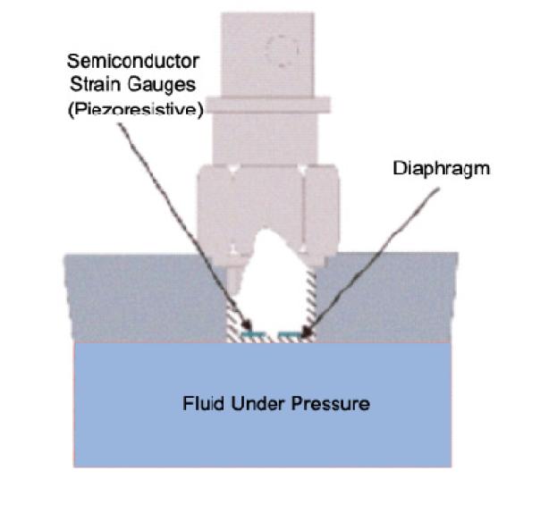
") LABORATORY MANUAL MEASUREMENTS & INSTRUMENTATION (ME- 318-F) LIST OF THE EXPERIMENT S. NO. NAME OF THE EXPERIMENT PAGE NO FROM TO 1. To measure stress and strain using strain gauge mounted on a cantilever
LABORATORY MANUAL MEASUREMENTS & INSTRUMENTATION (ME- 318-F) LIST OF THE EXPERIMENT S. NO. NAME OF THE EXPERIMENT PAGE NO FROM TO 1. To measure stress and strain using strain gauge mounted on a cantilever
COURSE OF Prepared By: MUHAMMAD MOEEN SULTAN Department of Mechanical Engineering UET Lahore, KSK Campus
 COURSE OF Active and passive instruments Null-type and deflection-type instruments Analogue and digital instruments In active instruments, the external power source is usually required to produce an output
e453.eps 1 Change (or the absolute value) in the measured physical variable 2 Change in the sensor property is translated into low-power-level
 in the measured physical variable 2 Change in the sensor property is translated into low-power-level") 3 Basic Phenomenon in Effect in Sensor Operation Measurement & Sensors Prof. Dr. M. Zahurul Haq http://teacher.buet.ac.bd/zahurul/ Department of Mechanical Engineering Bangladesh University of Engineering
3 Basic Phenomenon in Effect in Sensor Operation Measurement & Sensors Prof. Dr. M. Zahurul Haq http://teacher.buet.ac.bd/zahurul/ Department of Mechanical Engineering Bangladesh University of Engineering
EET LAB MANUAL. Term-062 UNIVERSITY DIPLOMA PROGRAM ELECTRONIC EQUIPMENT MAINTENANCE
 UNIVERSITY DIPLOMA PROGRAM ELECTRONIC EQUIPMENT MAINTENANCE EET - 027 ELECTRONICS INSTRUMENTATION LAB MANUAL Term-062 Lab Instructor MUHAMMAD AJMAL KHAN Lecturer Electrical Engineering Department Copyright
Using a Mercury itc with thermocouples
 Technical Note Mercury Support Using a Mercury itc with thermocouples Abstract and content description This technical note describes how to make accurate and reliable temperature measurements using an
- Copyright Dewesoft d.o.o., all rights reserved. Temperature measurement
 www.dewesoft.com - Copyright 2000-2019 Dewesoft d.o.o., all rights reserved. Temperature measurement Table of Contents Temperature and temperature scales 2 Types of temperature sensors 4 1. Thermocouples
Industrial Instrumentation Prof. Alok Barua Department of Electrical Engineering Indian Institute of Technology - Kharagpur
 Industrial Instrumentation Prof. Alok Barua Department of Electrical Engineering Indian Institute of Technology - Kharagpur Lecture - 9 Resistance Temperature Detector Welcome to the lesson 9 of Industrial
National 5 Physics. Electricity and Energy. Notes
 National 5 Physics Electricity and Energy Notes Name. 1 P a g e Key Area Notes, Examples and Questions Page 3 Conservation of energy Page 10 Electrical charge carriers and electric fields and potential
1. Mark the correct statement(s)
") 1. Mark the correct statement(s) Figure to the right shows a mass measurement scale using a spring. 1.1 The span of the scale is a) 16 kg b) 21 kg c) 11 kg d) 5-16 kg 1.2 The range of the scale is a) 16
1. Mark the correct statement(s) Figure to the right shows a mass measurement scale using a spring. 1.1 The span of the scale is a) 16 kg b) 21 kg c) 11 kg d) 5-16 kg 1.2 The range of the scale is a) 16
Summary Notes ALTERNATING CURRENT AND VOLTAGE
 HIGHER CIRCUIT THEORY Wheatstone Bridge Circuit Any method of measuring resistance using an ammeter or voltmeter necessarily involves some error unless the resistances of the meters themselves are taken
Exercise 1: Thermocouple Characteristics
 The Thermocouple Transducer Fundamentals Exercise 1: Thermocouple Characteristics EXERCISE OBJECTIVE When you have completed this exercise, you will be able to describe and demonstrate the characteristics
BASIC ELECTRONICS PROF. T.S. NATARAJAN DEPT OF PHYSICS IIT MADRAS LECTURE-3 ELECTRONIC DEVICES -II RESISTOR SERIES & PARALLEL
 BASIC ELECTRONICS PROF. T.S. NATARAJAN DEPT OF PHYSICS IIT MADRAS LECTURE-3 ELECTRONIC DEVICES -II RESISTOR SERIES & PARALLEL Hello everybody we are doing a course on basic electronics by the method of
California University of Pennsylvania. Department of Applied Engineering & Technology. Electrical / Computer Engineering Technology
 California University of Pennsylvania Department of Applied Engineering & Technology Electrical / Computer Engineering Technology EET 215: Introduction to Instrumentations Lab No.7 Temperature Measurement
1 Written and composed by: Prof. Muhammad Ali Malik (M. Phil. Physics), Govt. Degree College, Naushera
, Govt. Degree College, Naushera") CURRENT ELECTRICITY Q # 1. What do you know about electric current? Ans. Electric Current The amount of electric charge that flows through a cross section of a conductor per unit time is known as electric
CURRENT ELECTRICITY Q # 1. What do you know about electric current? Ans. Electric Current The amount of electric charge that flows through a cross section of a conductor per unit time is known as electric
Unit 3 Transducers. Lecture_3.1 Introduction to Transducers
 Unit 3 Transducers Lecture_3.1 Introduction to Transducers Introduction to transducers A transducer is a device that converts one form of energy to other form. It converts the measurand to a usable electrical
Ch. 23 Electromagnetic Induction, AC Circuits, And Electrical Technologies
 Ch. 23 Electromagnetic Induction, AC Circuits, And Electrical Technologies Induced emf - Faraday s Experiment When a magnet moves toward a loop of wire, the ammeter shows the presence of a current When
Sensors and Actuators Sensors Physics
 Sensors and ctuators Sensors Physics Sander Stuijk (s.stuijk@tue.nl) Department of Electrical Engineering Electronic Systems 2 THERMOELECTRIC SENSORS (Chapter 3.9, 16.4) 3 Thermoelectric effect thermoelectric
Module 4 : THERMOELECTRICITY Lecture 21 : Seebeck Effect
 Module 4 : THERMOELECTRICITY Lecture 21 : Seebeck Effect Objectives In this lecture you will learn the following Seebeck effect and thermo-emf. Thermoelectric series of metals which can be used to form
REPORT ON TRANSDUCERS TRANSDUCERS
 REPORT ON TRANSDUCERS TRANSDUCERS DEFINITIONS: TRANSDUCER A transducer is a device, usually electrical, electronic, electro-mechanical, electromagnetic, photonic, or photovoltaic that converts one type
For use with Comprehensive Secondary Physics
 SUB- 166 SUB- 167 For use with Physics Secondary Form Four Physics : Term One SUB- 1 Converging and diverging lenses diverging and converging lenses. Using light beams to distinguish between diverging
Temperature Measurements
 ME 22.302 Mechanical Lab I Temperature Measurements Dr. Peter Avitabile University of Massachusetts Lowell Temperature - 122601-1 Copyright 2001 A transducer is a device that converts some mechanical quantity
Process Control Instrumentation Technology Curtis D. Johnson Eighth Edition
 Process Control Instrumentation Technology Curtis D. Johnson Eighth Edition Pearson Education Limited Edinburgh Gate Harlow Essex CM20 2JE England and Associated Companies throughout the world Visit us
Making Contact with Temperature
 Making Contact with Temperature Here is a look at the phenomenon itself, the basic measurement technologies available, and how industry is presently using them. Jesse Yoder, Flow Research Temperature is
SEN TRONIC AG 1 A 6 6 / "
 1A 66/" 0!"#$%&'() %"*+", - %"*.", - /01234%( 34.+*!54%& 0*%/# "6#,7857.'.0" - 6#)9.:. &%&;! 0 &????'.&% )&" 8" @&& (++ '() %('.('/(#$!!! ' %! %!& ;!;8 ;!;8 0 &&'&&;! C;!C&(D"@@ &;! 0&&+%&;! C&=;!C&(D"@@
Chapter 6 Temperature Measurement (Revision 2.0, 1/12/2009)
") Chapter 6 emperature Measurement (Revision 2.0, /2/2009). Introduction his Chapter looks that various methods of temperature measurement. Historically, there are two temperature measurement scales: he
Chapter 6 emperature Measurement (Revision 2.0, /2/2009). Introduction his Chapter looks that various methods of temperature measurement. Historically, there are two temperature measurement scales: he
Laboratory 12: Three Thermodynamics Experiments
 Laboratory 12: Three Thermodynamics Experiments Experiment 1: Coefficient of Linear Expansion of Metals The fact that most objects expand when heated is common knowledge. The change in the linear dimensions
5. You may use the following values of physical constants wherever necessary. Class XII Physics (042) Sample Question Paper
 Sample Question Paper") Class XII Physics (04) Sample Question Paper 018-19 Time allowed: hours. Max. Marks: 70 General Instructions: 1. All questions are compulsory. There are 7 questions in all.. This question paper has four
Class XII Physics (04) Sample Question Paper 018-19 Time allowed: hours. Max. Marks: 70 General Instructions: 1. All questions are compulsory. There are 7 questions in all.. This question paper has four
Temperature Measurement
 Temperature Measurement Temperature is one of the most common measurements What is Temperature? Intuitively understood as sensation of hot/cold Early Researchers: Galileo (1564-1642) Newton (1642-1727)
EM375 MECHANICAL ENGINEERING EXPERIMENTATION THERMOCOUPLE LABORATORY
 EM375 MECHANICAL ENGINEERING EXPERIMENTATION THERMOCOUPLE LABORATORY PURPOSE The objective of this laboratory is to introduce the student to the manufacture and use of thermocouples. Thermocouples will
(Refer Slide Time: 01:16)
") Mechanical Measurements and Metrology Prof. S. P. Venkateshan Department of Mechanical Engineering Indian Institute of Technology, Madras Module - 4 Lecture - 50 Case Studies This will be lecture 50 in
Mechanical Measurements and Metrology Prof. S. P. Venkateshan Department of Mechanical Engineering Indian Institute of Technology, Madras Module - 4 Lecture - 50 Case Studies This will be lecture 50 in
Thermometry. History. History 1/21/18. The art or science of temperature observation
 Thermometry The art or science of temperature observation History No one person credited with the invention of the thermometer; developed over time Avicenna used this principal to show that hotness and
1 P a g e h t t p s : / / w w w. c i e n o t e s. c o m / Physics (A-level)
") 1 P a g e h t t p s : / / w w w. c i e n o t e s. c o m / Physics (A-level) Electromagnetic induction (Chapter 23): For a straight wire, the induced current or e.m.f. depends on: The magnitude of the magnetic
1 P a g e h t t p s : / / w w w. c i e n o t e s. c o m / Physics (A-level) Electromagnetic induction (Chapter 23): For a straight wire, the induced current or e.m.f. depends on: The magnitude of the magnetic
Name Class Date. RC Circuit Lab
 RC Circuit Lab Objectives: Students will be able to Use the ScienceWorkshop interface to investigate the relationship between the voltage remaining across a capacitor and the time taken for the discharge
Overview. Sensors? Commonly Detectable Phenomenon Physical Principles How Sensors Work? Need for Sensors Choosing a Sensor Examples
 Intro to Sensors Overview Sensors? Commonly Detectable Phenomenon Physical Principles How Sensors Work? Need for Sensors Choosing a Sensor Examples Sensors? American National Standards Institute A device
UNIVERSITY OF CAMBRIDGE INTERNATIONAL EXAMINATIONS General Certificate of Education Ordinary Level
 UNIVERSITY OF CAMBRIDGE INTERNATIONAL EXAMINATIONS General Certificate of Education Ordinary Level *7904310746* PHYSICS 5054/21 Paper 2 Theory October/November 2012 1 hour 45 minutes Candidates answer
PHYSICAL SCIENCES: PAPER I
 NATIONAL SENIOR CERTIFICATE EXAMINATION NOVEMBER 2014 PHYSICAL SCIENCES: PAPER I Time: 3 hours 200 marks PLEASE READ THE FOLLOWING INSTRUCTIONS CAREFULLY 1. This paper consists of: a question paper of
Measurement in Engineering
 Measurement in Engineering Responsible person for the course: Ing. Martin Novak, Ph.D. Report on the laboratory experiment Measurement of temperature of the 12.10.10 - made by Sebastian Kößler Report on
PHYSICS ORDINARY LEVEL
 *B16* PRE-LEAVING CERTIFICATE EXAMINATION, 2011 PHYSICS ORDINARY LEVEL TIME: 3 HOURS Answer three questions from section A and five questions from section B. Page 1 of 10 SECTION A (120 marks) Answer three
Cryogenic Instrumentation I Thermometry OUTLINE Thermometry Pt (pure metal) Temperature Ranges of Thermometer Application Typical Resistive Thermal
 Temperature Ranges of Thermometer Application Typical Resistive Thermal") Cryogenic Instrumentation I 1. Thermometry 2. anges of Application 3. Constant Volume 4. Thermocouples 5. Time esponse Data 6. 4 Terminal esistance Measurement OUTLINE 8. Pt (pure metal) 9. Typical esistive
Cryogenic Instrumentation I 1. Thermometry 2. anges of Application 3. Constant Volume 4. Thermocouples 5. Time esponse Data 6. 4 Terminal esistance Measurement OUTLINE 8. Pt (pure metal) 9. Typical esistive
Force and Displacement Measurement
 Force and Displacement Measurement Prof. R.G. Longoria Updated Fall 20 Simple ways to measure a force http://scienceblogs.com/dotphysics/200/02/diy_force_probe.php Example: Key Force/Deflection measure
QUESTION BANK DEPARTMENT OF ELECTRICAL AND ELECTRONICS ENGINEERING UNIT I - INTRODUCTION SYLLABUS
 QUESTION BANK DEPARTMENT OF ELECTRICAL AND ELECTRONICS ENGINEERING YEAR/SEM NAME OF THE SUBJECT NAME OF THE FACULTY : II / IV : EE6404 MEASUREMENTS AND INSTRUMENTATION : K.M.S.MUTHUKUMARA RAJAGURU, AP/EEE
ELECTRICAL MEASUREMENTS LAB MANUAL
 ELECTRICAL MEASUREMENTS LAB MANUAL Prepared by B.SAIDAMMA R13 Regulation Any 10 of the following experiments are to be conducted 1. Calibration and Testing of single phase energy Meter 2. Calibration of
Fig. 1. Two common types of van der Pauw samples: clover leaf and square. Each sample has four symmetrical electrical contacts.
 15 2. Basic Electrical Parameters of Semiconductors: Sheet Resistivity, Resistivity and Conduction Type 2.1 Objectives 1. Familiarizing with experimental techniques used for the measurements of electrical
Section 11: Magnetic Fields and Induction (Faraday's Discovery)
") Section 11: Magnetic Fields and Induction (Faraday's Discovery) In this lesson you will describe Faraday's law of electromagnetic induction and tell how it complements Oersted's Principle express an understanding
Section 11: Magnetic Fields and Induction (Faraday's Discovery) In this lesson you will describe Faraday's law of electromagnetic induction and tell how it complements Oersted's Principle express an understanding
1. Distinguish the important characteristics of instrument that are totally electrical and totally electronic in nature. [16]
![1. Distinguish the important characteristics of instrument that are totally electrical and totally electronic in nature. [16]](/thumbs/96/127822274.jpg "1. Distinguish the important characteristics of instrument that are totally electrical and totally electronic in nature. [16]") Code No: RR320204 Set No. 1 1. Distinguish the important characteristics of instrument that are totally electrical and totally electronic in nature. [16] 2. Distinguish between deterministic signals and
Code No: RR320204 Set No. 1 1. Distinguish the important characteristics of instrument that are totally electrical and totally electronic in nature. [16] 2. Distinguish between deterministic signals and
EXPERIMENT VARIATION OF THERMO-EMF WITH TEMPERATURE. Structure. 7.1 Introduction Objectives
 EXPERIMENT 7 VARIATION OF THERMO-EMF WITH TEMPERATURE Thermo-EMF Structure 7.1 Introduction Objectives 7.2 Working Principle of a Potentiometer 7.3 Measurement of Thermo-EMF and its Variation with Temperature
REVISED HIGHER PHYSICS REVISION BOOKLET ELECTRONS AND ENERGY
 REVSED HGHER PHYSCS REVSON BOOKLET ELECTRONS AND ENERGY Kinross High School Monitoring and measuring a.c. Alternating current: Mains supply a.c.; batteries/cells supply d.c. Electrons moving back and forth,
5. ELECTRIC CURRENTS
 5. ELECTRIC CURRENTS TOPIC OUTLINE Section Recommended Time Giancoli Section 5.1 Potential Difference, Current, Resistance 5.2 Electric Circuits 3h 19.1, 19.2 6.2 Electric Field and Force 6.3 Magnetic
AE60 INSTRUMENTATION & MEASUREMENTS DEC 2013
 Q.2 a. Differentiate between the direct and indirect method of measurement. There are two methods of measurement: 1) direct comparison with the standard, and 2) indirect comparison with the standard. Both
Temperature Sensors & Measurement
 Temperature Sensors & Measurement E80 Spring 2014 Contents Why measure temperature? Characteristics of interest Types of temperature sensors 1. Thermistor 2. RTD Sensor 3. Thermocouple 4. Integrated Silicon
Section 11: Magnetic Fields and Induction (Faraday's Discovery)
") Section 11: Magnetic Fields and Induction (Faraday's Discovery) In this lesson you will describe Faraday's law of electromagnetic induction and tell how it complements Oersted's Principle express an understanding
Section 11: Magnetic Fields and Induction (Faraday's Discovery) In this lesson you will describe Faraday's law of electromagnetic induction and tell how it complements Oersted's Principle express an understanding
Solar Flat Plate Thermal Collector
 Solar Flat Plate Thermal Collector INTRODUCTION: Solar heater is one of the simplest and basic technologies in the solar energy field. Collector is the heart of any solar heating system. It absorbs and
Electromagnetic Flowmeter
 Overview Flokal B.V. smart electromagnetic flow meter is hallmarked by its high performance and reliability that are based on successful, field-proven technology. It s being widely used in industries such
Study of Resistance Components
 Study of Resistance Components Purpose: The purpose of this exercise is to apply fundamental electrical circuit concepts to determine the response of electrical components subjected to a mechanical input
Temperature Calibration
 Temperature Calibration Application Note Temperature plays a key role in many industrial and commercial processes. Examples include monitoring cooking temperature in food processing, measuring the temperature
HMS-5000 Manual. Product Name: HMS-5000 Hall Effect Measurement System with variable temperature from 80K to 350K. - Manual version: ver 5.
 HMS-5000 Manual Product Name: HMS-5000 Hall Effect Measurement System with variable temperature from 80K to 350K - Manual version: ver 5.01- www.ecopia21.co.kr - Table of contents - 1. Hardware Installation
Electricity and magnetism. Verifying the Lenz Law by measuring the electric current flowing through a coil created by an external magnetic field
 Verifying the Lenz Law by measuring the electric current flowing through a coil created by an external magnetic field Dimension 2 Cross Cutting Concepts Dimension 1 Science and Engineering Practices Electricity
c = m/s h = Js e = C µ 0 = 4 π 10 7 T ma l ε 0 = C 2 N 1 1 = N m 2 C 2 me = 9.
 CLASS: XII SUBJECT: PHYSICS MAX. MARKS: 70 TIME: 3 Hours General Instructions: (i) All questions are compulsory. There are 2 questions in all. (ii) This question paper has five sections: Section A, Section
DUBLIN INSTITUTE OF TECHNOLOGY Kevin Street, Dublin 8.
 Question Sheet Page 1 of 5 Instructions for the student: Question 1 is compulsory [40 marks] Attempt any two other questions [30 marks per question] The following must be made available during the examination:
Harnessing the Power of Arduino for the Advanced Lab
 P P Herbert Jaeger + Harnessing the Power of Arduino for the Advanced Lab (Final Version) ALPhA Immersion Workshop July 27 29, 2017 Department of Physics Indiana University Purdue University Ft. Wayne,
Subject: BT6008 Process Measurement and Control. The General Control System
 WALJAT COLLEGES OF APPLIED SCIENCES In academic partnership with BIRLA INSTITUTE OF TECHNOLOGY Question Bank Course: Biotechnology Session: 005-006 Subject: BT6008 Process Measurement and Control Semester:
ELECTRIC CURRENTS D R M A R T A S T A S I A K D E P A R T M E N T O F C Y T O B I O L O G Y A N D P R O T E O M I C S
 ELECTRIC CURRENTS D R M A R T A S T A S I A K D E P A R T M E N T O F C Y T O B I O L O G Y A N D P R O T E O M I C S lecture based on 2016 Pearson Education, Ltd. The Electric Battery Electric Current
ECE 220 Laboratory 4 Volt Meter, Comparators, and Timer
 ECE 220 Laboratory 4 Volt Meter, Comparators, and Timer Michael W. Marcellin Please follow all rules, procedures and report requirements as described at the beginning of the document entitled ECE 220 Laboratory
AISSCE 2016 EXPECTED (SURE SHORT) QUESTIONS WEIGHTAGE-WISE 2016
 QUESTIONS WEIGHTAGE-WISE 2016") CLASS: XII AISSCE 2016 Subject: Physics EXPECTED (SURE SHORT) QUESTIONS WEIGHTAGE-WISE 2016 Q3 Section A ( 1 Mark ) A force F is acting between two charges placed some distances apart in vacuum. If a brass
CLASS: XII AISSCE 2016 Subject: Physics EXPECTED (SURE SHORT) QUESTIONS WEIGHTAGE-WISE 2016 Q3 Section A ( 1 Mark ) A force F is acting between two charges placed some distances apart in vacuum. If a brass
Induction_P1. 1. [1 mark]
![Induction_P1. 1. [1 mark]](/thumbs/88/115570773.jpg "Induction_P1. 1. [1 mark]") Induction_P1 1. [1 mark] Two identical circular coils are placed one below the other so that their planes are both horizontal. The top coil is connected to a cell and a switch. The switch is closed and
Induction_P1 1. [1 mark] Two identical circular coils are placed one below the other so that their planes are both horizontal. The top coil is connected to a cell and a switch. The switch is closed and
SENSORS and TRANSDUCERS
 SENSORS and TRANSDUCERS Tadeusz Stepinski, Signaler och system The Thermal Energy Domain Physics» Seebeck effect» Peltier effect» Thomson effect Thermal effects in semiconductors Thermoelectric sensors
AP Physics C - E & M
 AP Physics C - E & M Current and Circuits 2017-07-12 www.njctl.org Electric Current Resistance and Resistivity Electromotive Force (EMF) Energy and Power Resistors in Series and in Parallel Kirchoff's