TECHNICAL REPORT. Bending tests on glulam-clt beams connected with double-sided punched metal plate fasteners and inclined screws.
|
|
|
- Bennett Singleton
- 5 years ago
- Views:
Transcription


1 TECHNICAL REPORT Bending tests on glulam-clt beams connected with double-sided punched metal plate fasteners and inclined screws Nicolas Jacquier
2 ISSN ISBN (pdf) Luleå 15

3 Bending tests on glulam-clt beams Connected with double-sided punched metal plate fasteners and inclined screws Nicolas Jacquier Luleå University of Technology Department of Civil, Environmental and Natural Resources Engineering Division of Structural and Construction Engineering
4 Abstract This report presents bending tests performed on composite beams made from glulam beams and cross laminated timber (CLT) panels. The composite beam, with a T-cross section, represents a section of a floor element in a multi-storey CLT construction system. The shear connections used were made either of doublesided punched metal plate fasteners, either of inclined screws, or of a combination of both fastener types. The screws are used to secure the shear connection with double-sided nail plates with respect to possible separation forces between the glulam and the CLT. An additional test with a screw glued connection was made for comparison as the upper bound case in terms of composite action. The results show the beams with double-sided nail plates (with or without screws) achieved a very high level of composite action and an overall satisfactory behaviour. Almost full composite action was achieved for the screw-glued composite beam. A detailed design example of the beam element according to the Eurocode 5 and Finnish National Annex is presented. screws 1
5 Table of Contents Abstract... 1 Table of Contents... 1 Introduction... 4 Methods Shear connectors Glulam and CLT members Design method Design of the mechanically jointed glulam-clt beam according to the γ-method Serviceability design criteria Test series Preparation, conditioning and assembly Test setup Considered design load for the serviceability and ultimate limit states Experimental results General Failure observations Series B1_S (Inclined screws only) Series B_NP (Double-sided nail plates only) Series B3_NP+S (Double-sided nail plates and inclined screws combined) Series B4_SG (Screw-gluing) Load-deflection curves individual test series Slip measurements along the beam length - individual test series Bending stiffness of the composite beams Estimation of the floor element fundamental frequency Longitudinal slip at the glulam-clt interface Discussion Combination of inclined screws and double-sided nail plates Floor element layout and failure Design and buildability considerations Conclusions Appendix A: Design of a glulam-clt element according to Eurocode 5 and Finnish National Annex... 3 Appendix B: Additional load-deflection and slip measurements Series B1_S (Inclined screws only) Series B_NP (Double-sided nail plates only)... 5 screws
6 Series B3_NP+S (Double-sided nail plates and inclined screws combined) Series B4_SG (Screw-gluing) Appendix C: Tables of test results per test series Notations Series B1_S (Inclined screws only) Series B_NP (Double-sided nail plates only) Series B3_NP+S (Double-sided nail plates and inclined screws combined)... 6 Series B4_SG (Screw-gluing) Acknowledgements... 6 References... 6 screws 3
7 1 Introduction A composite timber floor made with glulam and Cross Laminated Timber (CLT) and its shear connection system are investigated in a bending situation. An example of glulam-clt cassette floor element with CLT at the bottom is shown in Fig. 1 and is a possible floor configuration considered in a residential multi-storey CLT construction system. Only the CLT panel and the glulam beams are load bearing. The shear connection considered is made of double-sided punched metal plate fasteners in combination with inclined screws. The behaviour of joints with double-sided nail plates (DSNP) and inclined screws combined was evaluated under shear tests [1]. The screws are used to compensate the lack of withdrawal resistance of the double-sided nail plates and to improve the overall joint behaviour (strength, stiffness and post peak-load behaviour). More background information and motivation for this study is presented in [1] and []. The aim of the study is to evaluate the performance (strength, stiffness, behaviour) of composite timber beam elements with DSNP shear connectors and to evaluate the influence of additional screws on the overall beam performance. The study intends to evaluate the technical feasibility of a particular design of a glulam-clt composite floor made with such shear connectors by proposing and testing a likely design of a floor element of 6.4 m span, for which a detailed design example is presented in Appendix A. The experimental program presented in this report also considers the combination of double-sided nail plates and inclined screws. Three bending tests series (of 3 test specimens each) with different arrangements of mechanical fasteners (DSNP and screws) were performed on glulam-clt beam elements assembled with either: - double-sided nail plate (DSNP) fasteners; - inclined (45 ) self-tapping screws; - double-sided nail plates (DSNP) combined with inclined (45 ) self-tapping screws. Fig. 1: Example of a glulam-clt cassette floor element with CLT panel located at the bottom. screws 4
 of glulam-clt composite beams connected with mechanical fasteners were tested under 4-point bending tests corresponding to a likely design of a floor element in")
8 Methods The experimental test program was carried at the laboratories of VTT Expert Services Ltd in Finland. Three series (of 3 specimens each) of glulam-clt composite beams connected with mechanical fasteners were tested under 4-point bending tests corresponding to a likely design of a floor element in order to investigate the behaviour and performance of different shear connection configurations. An additional single bending test was performed on a screw-glued composite beam in order to compare beams connected with mechanical fasteners and beams with a glued shear connection and therefore an assumed full composite action. The beams were 6.5 meter long and had the same cross-section, shown in Fig. for the case of a connection with combined double-sided nail plate and inclined screw. This cross-section corresponds to the total floor element presented in Fig. 1 reduced to a single beam element. Fig. : Cross section of the composite glulam-clt beam with double-sided nail plate and inclined screw shear connection (dimensions in mm)..1 Shear connectors The shear connectors considered are double-sided punched metal plate fasteners (Fig. 3) and self-tapping screws (Fig. 4). The configurations of the shear connectors in the different test series is given in section.4. Fig. 3: Double-sided punched metal plate Sepa-SEP, (dimensions b NP l NP ) 7 mm. screws 5
9 The double-sided punched metal plate fasteners Sepa-SEP (Fig. 3) are made of zinc coated steel with dimensions (b NP l NP ) 7 mm, steel plate thickness 1.3 mm and teeth length 15.6 mm. Mechanical properties (mean values) according to the manufacturing s inspection certificate are: tensile yield strength f y = 41 N/mm, ultimate tensile strength f u = 485 N/mm, elongation ε u = 8. % and weight of zinc coating 93 g/m. Fig. 4: SFS-Intec WT-T screw geometry with diameter 6.5 mm (source SFS Intec [3]). SFS Intec WT-T self-drilling screws (Fig. 4) are used in series with inclined screws. The screw nominal dimensions (d L in mm) (thread length s g 65 mm) and properties are according to the European Technical Approval ETA-1/63 [3]. The load-carrying capacity and slip modulus for the individual shear connectors obtained from shear tests on glulam-clt joints [1] are reported in Table 1. Table 1: Load-carrying capacity, slip modulus and specific slip values for single shear connectors [1]. Shear connector type Slip at Load-carrying (Test series name as reported Slip modulus Yield slip maximum capacity in [1]) load F max (CoV) kn (%) k s (CoV) kn/mm (%) u y (CoV) mm (%) u max (CoV) mm (%) Screw SFS-WT-T inclined at α = (5.3) 9.7 (7.3).67 (19.9) 1.78 (9.4) (S1_S-6.5) Double-sided nail plate Sepa- SEP (S8_1NP-) 3.9 (.9) 53.6 (7.8).7 (1.4) 5.6 (8.8) A one-component polyurethane glue Purbond HB11 (5 gr/m) was used for the screw-glued specimen. Vertical SFS Intec screws WFD-T-H were used with 8 mm diameter washers (Fig. 5) to apply the necessary pressure on the glue line. Dimensions d, L1, and L in Fig. 5 are 8 mm, 18mm, and 18 mm, respectively. screws 6
10 (a) (b) Fig. 5: Screw and washer used for screw-gluing: (a) SFS Intec WFD-T-H1-8 18; (b) 8 mm washer (source SFS Intec [4]).. Glulam and CLT members The glulam used was made of Norway Spruce (Picea abies) and labelled L4 (Nordic glulam strength class) and GL3 [5]. The glulam beams of length 65 mm had a cross section of mm with glulam lamellas thickness of 45 mm. The CLT was manufactured from solid wood lamellas of strength class C4 according to European Technical Approval ETA-8/71 [6], composed of three mm thick layers with the outer ply grain oriented parallel to the span direction. The CLT panels of length 65 mm had a cross section of 6 58 mm. The global modulus of elasticity (MOE) according to EN 48 [7] was measured on three glulam beams and three CLT panels by 4-point bending load test up to.4 F max,est,with F max,est taken equal to 18 kn and 3 kn for the glulam beams and the CLT panels, respectively. The global MOE obtained for the glulam was E global,glulam = N/mm when neglecting the shear deformation. When considering the deflection due to shear deformation and assuming a shear modulus of 85 N/mm according to the GL3h strength class, the estimated MOE was E global,glulam,shear = 1 9 N/mm. Regarding the CLT the vertical shear deformation is neglected for the CLT as the span is very large in comparison to the CLT layers thicknesses. The global MOE of the longitudinal layers was estimated using the γ -method (cf. section.3.1), considering the contribution of the top and bottom layers only and the rolling shear deformation in the traverse layer with a rolling shear modulus G R = 5 N/mm [8], giving E global,clt = N/mm for the longitudinal CLT layers. In this test report the values E global,glulam = N/mm and E global,clt = N/mm are considered as the measured MOE of the glulam and CLT members, respectively. screws 7
11 .3 Design method The floor element investigated is intended to be used in Finland. The design of the composite beam element was therefore made according to the Eurocode 5 [9] and Finnish National Annex [1], and using preliminary test results for the shear connectors. The test specimens represent a likely design of a floor element which could be used in Finland. A detailed design example of the beam element is presented in Appendix A..3.1 Design of the mechanically jointed glulam-clt beam according to the γ-method In the Eurocode 5, the design of mechanically jointed timber beams can be done with the so-called γmethod. It is generally accepted that the design of horizontal CLT members in bending can also be done with the γ-method considering that only the longitudinal layers are load-carrying, and that the perpendicular ones act as flexible shear connections [11], [8]. In the γ-method, the ratio s/k in the usual expression of the γ factor, see Eq. (), where s 1 [m] is the spacing of the individual mechanical fasteners and k 1 [kn/m] is the slip modulus of an individual mechanical fastener [N/m], should be replaced by the ratio h/(g R b), see Eq. (3), where h 3 [m] is the thickness of the perpendicular CLT layer (here between the sub-element and 3), G R [N/m ] is the rolling shear modulus and b 3 [m] is the width of the perpendicular CLT layer (usually, as it is the case here b 3 = b = b 3 ). The γ-method can be used for composite cross-sections up to three layers (with two flexible layers), and it can therefore be used for the glulam-clt composite beam presented in this report. It should be noted that other methods allow to take into account the shear deformations in the CLT and to treat structures with more than three layers. These methods are not presented in the Eurocode 5 and do not permit to carry out simple hand calculation. They are therefore out of the scope of the present design procedure description. Fig. 6: Glulam-CLT cross-section and stress diagram with the notation considered in the γ-method. screws 8
12 The effective bending stiffness EI ef of the composite glulam-clt beam element is calculated as follows: 3 ef ( i i i i i i ) i1 EI E I E Aa (1) where E i, A i and I i are the modulus of elasticity, the area and the second moment of area of the i th sub-element in Fig. 6, respectively, γ = 1 and where: EAs kl 1 1 () EAh Gb R 3L 1 (3) a h1 h h h3 1E1A1 3E3A3 h3 EA EA EA (4) h1 h a1 a (5) h h3 a3 h3 a (6) where s 1 and k 1 are the spacing and the slip modulus, respectively, of the individual shear connectors between the sub-element 1 and, and h 1, h, h 3 and h 3 are the respective heights of the different sub-elements according to Fig. 6. The normal stress σ i and bending stress σ m,i in each sub-element, Eq. (7) and Eq. (8), respectively, and the force F 1 in a single shear connector, Eq. (9), can be calculated according to the expressions given in the Eurocode 5: Ea M i i i i EI (7) ef.5eh i i M mi, EI (8) ef where M is the external moment at the position of interest and h i is the height of the sub-element evaluated; F E Aas V EI (9) ef where V is the total shear force at the position of the fastener considered. screws 9
13 Conservatively, it can be assumed for the shear stress verification in the glulam that the glulam beam resists the entire shear force as suggested in [1] for the design of a LVL-concrete composite structure using Eq. (1): 1,max (1) 1.5 V A 1 where V is the total shear force at the position considered. The verification which must be carried out in the CLT with respect to the shear force concerns the transverse layer with the verification of the rolling shear stresses, the rolling shear strength being much lower than the shear strength for the layers loaded parallel. The rolling shear stresses in the cross-layer can be calculated by assuming a constant uniform shear stress distribution over this layer equal to the shear stress level at the interface between the sub-elements and 3 with Eq. (11): E Aa V v,3 EIef b (11) 3 A more conservative assumption is to consider that the shear stresses are distributed from the glulam beam down to the perpendicular layer with a 45 angle distribution, therefore virtually reducing the resisting width of the cross-layer. The rolling shear stress could therefore alternatively (alt) be calculated with Eq. (1): v,3,alt 3EAa V EI ( b h ) ef 1 (1).3. Serviceability design criteria The Finnish National Annex [13] of the Eurocode 5 [9] specifies that timber floors should have a fundamental frequency of at least 9 Hz or that a special investigation should be carried out. It is suggested that for simply supported floors on only two sides, the fundamental frequency can be calculated with Eq. (13): f1 L EI m l (13) where L is the floor span, (EI) l is the equivalent plate bending stiffness of the floor about an axis perpendicular to the span direction [Nm /m], and m is the mass of the floor to consider calculated as m = m G + 3 kg/m, where m G is the self-weight of the finished floor element and where the term 3 kg/m accounts for the permanent part of the service load [14]. The Finnish National Annex formerly specified to calculate the contributing floor mass as mmg qk with the partial coefficient for the quasi-permanent load combination and qk the characteristic service load for the floor. screws 1
14 The Finnish National Annex also recommends that floors having a fundamental frequency higher than 9 Hz should also verify that the maximum deflection δ 1kN (Eq. (14)) caused by a static concentrated loading P = 1 kn should not exceed.5 mm, calculated: 3 PL PL 1kN min 4 k EI l 4 s EI l (14) where k δ (Eq. (15)) is a coefficient accounting for the distribution of the concentrated load over the floor width depending on the bending stiffness of the floor with respect to an axis parallel to the span direction (EI) b [Nm /m], B is the floor width, and s the spacing of the floor beams. k B min L 4 EI EI l b (15) The contribution of the additional floor finishes layers (i.e. floating floor) can be considered in addition for the transverse bending stiffness (EI) b and can allow to distribute even more the concentrated load over the floor width. The unit impulse velocity response ν [m/(n s f )] according to Eqs. (16) and (17) should verify 1 1 b, where according to the Finnish National Annex b = 15 and ζ is the modal damping ratio of the floor. 4(.4.6 n4) mbl (16) n 4 4 f1 L EI 4 B EI l 1 b.5 (17) screws 11
15 .4 Test series The test series are described in Table and Fig. 7. The shear connection of the specimens of the series B_NP (double-sided nail plates only) and B3_NP+S (double-sided nail plates and screws combined) were designed so that the finished floor would have a fundamental frequency of at least 9 Hz for a load case consisting of a uniformly distributed permanent load G k = 1.8 kn/m and a service load Q k = kn/m. The beam B1_S was under-designed with a minimal shear connection made with a small amount of screw as the lower bound case from a composite action point of view. A constant spacing of the connectors along the beam s = 45 mm was used in all series except for the single test made with screw-gluing where the spacing between vertical screws was mm, representing the upper bound case aiming for full composite action. Table : Description of the test series: screws only (B1_S), double-sided nail plates only (B_NP), double-sided nail plates and screws combined (B3_NP+S), and screw-gluing (B4_SG). Test series Name No. of tests Estimated load F est (kn) Spacing s = 45 mm Screws inclined at Double-sided nail 45 (shear tension) plates d l s (mm) b NP l NP (mm) Spacing s = mm Vertical screws for screw-gluing d l s (mm) B1_S B_NP B_NP+S B4_SG d is the nominal screw diameter, l s is the screw length, b NP and l NP are the DSNP width and length, respectively. Fig. 7: Configuration of the test series: (a) screws only (B1_S), (b) double-sided nail plates only (B_NP), (c) double-sided nail plates and screws (B3_ NP+S), (d) screw-gluing (B4_SG). screws 1


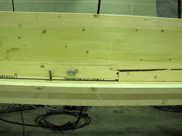
16 .5 Preparation, conditioning and assembly The timber members were stored at 65 % relative humidity (RH) and C temperature (T) for 8 at least weeks before assembly. After assembly with the double-sided nail plates fasteners, the composite beams were stored again in the climate controlled room under the same conditions for 4 weeks before the bending tests. The beam elements with double-sided nail plates were assembled in two steps in the laboratory by pressing first each double-sided nail plate individually into the CLT panel using a steel comb for double-sided nail plate (Fig. 8) and a load-controlled hydraulic jack with 55 kn per double-sided nail plate. After the installation of all the nail plates of the specimen in the CLT, the glulam beam was pressed onto the CLT panel using two hydraulic jacks applying each a force on a steel beam distributing the load over the glulam beam length (Fig. 9). A total load of 77 kn was applied on the glulam beam to press simultaneously the 14 double-sided nail plates of each test specimen. Fig. 8: Positioning and pressing the double-sided nail plates on the CLT panel. screws 13


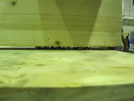
17 Fig. 9: Pressing of the glulam beam onto the DSNP preinstalled in the CLT with distributing steel beams. Some double-sided nail plates were not fully pressed towards the ends of the two distributing steel beams. An additional pressing was done at the end of the beam until full contact was achieved. The pressing depth of the double-sided nail plate teeth was satisfactory with an average gap of less than mm between the members. The nails of the nail plates become visible when the gap between the glulam and CLT elements exceeds.5 mm, see Fig. 1-a and Fig. 1-b. A remaining gap (about 3 mm) was observed at some locations for most of the specimens after the assembly was finished, usually at the second and third double-sided nail plate from the beam ends, and at the two ones at mid span. (a) (b) Fig. 1: Difference of pressing depth of the nail plates at different locations in the same beam: (a) Double-sided nail plate fully pressed (gap <.5 mm); (b) Double-sided nail plate with gap on the glulam side (gap.5 mm). screws 14

18 The inclined self-drilling screws of the test specimens B1_S and B3_NP+S were inserted some hours before carrying out the tests with a specific tool to control the 45 degree angle (Fig. 11). Fig. 11: Assembly of the composite beam elements with inclined screws at 45. The assembly of the specimen with screw-gluing was done in the climate controlled room under 65% relative humidity and C temperature. The glue opening time was 18 minutes, and the specimen cured for 4 hours before testing. Figure 1: Assembly of the screw-glued beam in the climate controlled room. screws 15

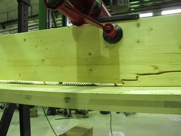
19 .6 Test setup The bending tests were carried out under a four-points loading test arrangement. The composite beam lied on two poined supports with one having the possibility to slide horizontally. The support length was 1 mm on each side and represented the actual support conditions of a floor element on a CLT wall. The beam was supported over the entire CLT element width. The concentrated loads were positioned at the third points of the beam span of 6.4 m and distributed to the top of the glulam beam via two thick steel plates (5 mm 9mm). Fig. 13: Bending test setup (#1 to #8: LVDT longitudinal slip measurement; #9: mid-span global deflection measurement) Fig. 14: View of the bending test setup The global deflection at mid-span was measured from the bottom of the CLT panel with a Tokyo Sokki DP- 5E inductive sensor. The longitudinal slip at the CLT-glulam interface was measured with linear displacement transducers (HBM-W1-TK) at each second shear connector positions along the beam from the beam ends (Fig. 13). The load was applied under load-control for the entire test with two VEB hydraulic jacks and measured by Instron UPM load cells, following the EN 6891 [15] loading procedure. The tests were stopped at the collapse of the beam. screws 16
20 Specific measurements for the deflection at mid-span δ and the slip ν at certain load levels according to EN 6891 (cf. Fig. 15) are reported in Appendix C for each test specimen. Fig. 15: Measurement points on a load-deformation curve according to EN Considered design load for the serviceability and ultimate limit states The load levels corresponding to the serviceability limit state (SLS) for the characteristic load combination w SLS and to the ultimate limit state (ULS) for the fundamental load combination w ULS are defined from the uniformly distributed load case (G k = 1.8 kn/m and Q k = kn/m ) for which the floor element is designed. The corresponding load levels considered in the 4-point bending test are noted, F SLS and F ULS, are obtained from the equivalence of the bending moment under the uniformly distributed loading and 4-point loading cases, with F = P = (3 w L)/4, where F is the total load applied, P is a single point load (Fig. 13), w is the distributed load case and L is the span of the beam. Therefore, the load levels considered for the floor reduced cross-section of 58 mm width in the SLS and ULS are F SLS = 1.6 kn and F ULS = 14.1 kn, respectively. These values are used to evaluate the bending stiffness and performance of the shear connections from a practical point of view. screws 17
21 3 Experimental results 3.1 General The load-deflection curves for all tests specimens tested are presented in Fig. 16. The collapse of the specimen is indicated by a marker at the end of each curve representing the end of the test. The design load levels considered F SLS and F ULS, defined in section.7, are also represented in Fig. 16. The dashed lines represent the theoretical load-deflection calculated according to the γ-method (cf. section.3.1) using the measured global modulus of elasticity for each timber member (cf. section.) and the slip modulus values from Table 1 and calculated with Eq. (18). Fa 3L 4a (18) 48EI The bending stiffness values used EI ef,sls,calc are given in Table 4. In beam configurations with combined shear connectors (DSNP and screws) the slip moduli of the different fastener types are added as suggested in [1]. For the screw-glued shear connections, full composite action between glulam and CLT is assumed. The flexibility due to the cross layer in the CLT panel remains considered in all cases. Fig. 16: Load-deflection curves for the four-point bending tests and calculated theoretical load-deflections screws 18
22 In Fig. 17, average load-deflection curves are presented up to 8% of the average maximum load of each test series B1_S B_NP B3_NP+S B4_SG Deflection (mm) Fig. 17: Mean load-deflection curves for series B1_S, B_NP and B3_NP+S, and single curve for B4_SG up to 8% of F max for the test series (mean value) The main results for each test series (mean values) are presented in Table 3 with the mean density ρ g,ω and ρ c,ω of the glulam and CLT members at the time of testing, respectively, the moisture content ω measured just after the bending tests, the maximum load F max, the bending stiffness EI 4.Fmax estimated between 1 % and 4 % of the observed maximum load F max, the bending stiffness EI F.SLS estimated between the load levels F SLS and F SLS /4, the deflection at mid-span δ SLS at the load F SLS, and the ratio L/δ SLS where L is the span of the beam element. Table 3: Summary of the bending test results for the series with screws only (B1_S), nail plates only (B_NP), nail plates and screws combined (B3_NP+S), and screw gluing (B4_SG) Mean values. Test series No. of tests Glulam CLT D MC D MC ρ g,ω kg/m 3 ω g (%) ρ c,ω kg/m 3 ω c (%) B1_S B_NP B3_NP+S Maximum load F max (CoV) kn (%) 69.4 (6.) 87.4 (3.4) 94. (5.9) Failure load F f (CoV) kn (%) 67.7 (7.4) 8.1 (.) Mid-span deflection at.4 F max δ 4 Fmax (CoV) mm (%) 39.9 (1.8) 6.8 (.7) Span to deflection ratio at.4 F max L/δ 4 Fmax Mid-span deflection at F SLS δ SLS (CoV) mm (%) 11.7 (7.4) 7.58 (3.5) Span to deflection ratio at B4_SG D = density, MC = Moisture Content 93.9 (5.8) 7. (.) (4.) F SLS L/δ SLS screws 19


. The timber members were tightly connected before failure. In series B_NP the ultimate failure occurred in the glulam member.")

23 3. Failure observations The test specimens with mechanical fasteners shear connection (series B1_S, B_NP and B3_NP+S) failed by a tensile bending failure of the glulam beams starting from a finger joint or a knot in most of the cases. No visible damage could be observed in the CLT panels. Compression failure could be observed on the upper side of the glulam member between the points of load application for all test series, often down to the second glulam lamella. The ultimate failure occurred in B1_S in the glulam member, triggering the sudden withdrawal some screws (both pull-through and pull out was observed). The timber members were tightly connected before failure. In series B_NP the ultimate failure occurred in the glulam member. Before the glulam beam failure, the withdrawal of the DSNP could be observed and is characterised by a slight reduction of the load in Fig. 3 before failure. In series B3_NP+S, the inclined screws seem to have prevented the separation before the failure of the glulam beam, providing a slightly higher maximum load to the composite beam Series B1_S (Inclined screws only) Fig. 18: Pictures of beam specimens after failure (Series B1_S) screws


24 3.. Series B_NP (Double-sided nail plates only) Fig. 19: Pictures of beam specimens after failure (Series B_NP) screws 1


25 3..3 Series B3_NP+S (Double-sided nail plates and inclined screws combined) Fig. : Pictures of beam specimens after failure (Series B3_NP+S) screws
26 3..4 Series B4_SG (Screw-gluing) For the specimen B4_SG, a tensile bending failure in the CLT panel (Fig. 1 (b) and (d)) and a very large compression failure at the top of the glulam beam were observed (Fig. 1 (b) and (c)). The compression failure, located near the load application point, extended down to half the height of the glulam beam, and could be observed before the CLT panel failure (Fig. 1 (a)). The glue line at the glulam-clt interface did not fail and no separation of the members was observed. (a) (b) (c) (d) Fig. 1: Failure observations series B4_SG: (a) large compression failure of the glulam beam before collapse, (b) compression failure of the glulam and tension failure of the CLT, (c) compression failure of the glulam, (d) tensile bending failure of the CLT. screws 3
27 3.3 Load-deflection curves individual test series. The load-deflection curves at mid-span are presented in Fig. to Fig. 5 for each test series with a closer view up to about 5% of the estimated failure load F est. The individual load-deflection curves and load-slip measurements along the beam are presented for each test specimen individually in Appendix B with more detailed tables of results, Appendix C. In Fig. (Series B1_S), a change in the slope at about 13 kn can be observed, indicating a change in the shear connection behaviour. A clear sound of static friction being exceeded at regular time intervals (about 1 s) and causing regular slip increments could be heard along the tests, starting at about 1 kn B1_S (1) 1 B1_S () B1_S (3) Mid-span deflection (mm) B1_S (1) 5 B1_S () B1_S (3) Mid-span deflection (mm) Fig. : Load-deflection curves at mid-span (full curves and curves up to 5% of F est ) - Series B1_S B_NP (1) 1 B_NP () B_NP (3) Mid-span deflection (mm) B_NP (1) 5 B_NP () B_NP (3) Mid-span deflection (mm) Fig. 3: Load-deflection curves at mid-span (full curves and curves up to 5% of F est ) - Series B_NP screws 4
28 B3_NP+S (1) 1 B3_NP+S () B3_NP+S (3) Mid-span deflection (mm) B3_NP+S (1) 5 B3_NP+S () B3_NP+S (3) Mid-span deflection (mm) Fig. 4: Load-deflection curves at mid-span (full curves and curves up to 5% of F est ) - Series B3_NP+S B4_SG (1) Mid-span deflection (mm) B4_SG (1) Mid-span deflection (mm) Fig. 5: Load-deflection curves at mid-span (full curves and curves up to 5% of F est ) - Series B4_SG screws 5
29 3.4 Slip measurements along the beam length - individual test series. The measured slip ν at the glulam-clt interface is plotted in Fig. 6 to Fig. 8 along the beam length for the test series B1_S, B_NP and B3_NP+S at certain load values F 1, F 4, F 6, F 8, F max, and F failure, (F failure being the last load level recorded before a drop of load of more than %). For the series B4_SG the slip was only measured at both beam ends and is presented in the result tables in Appendix C. 15 B1_S (1) 15 B1_S () 15 B1_S (3) 1.F.est F.est 6.F.max 8.F.max F.max failure 4 6 Longitudinal beam axis (m) 4 6 Longitudinal beam axis (m) 4 6 Longitudinal beam axis (m) Fig. 6: Slip measurements along the beam length at the load levels F 1, F 4, F 6, F 8, F max, and F failure Series B1_S 1 B_NP (1) 1 B_NP () 1 B_NP (3) F.est F.est 6.F.max 8.F.max F.max failure 4 6 Longitudinal beam axis (m) 4 6 Longitudinal beam axis (m) 4 6 Longitudinal beam axis (m) Fig. 7: Slip measurements along the beam length at the load levels F 1, F 4, F 6, F 8, F max, and F failure Series B_NP 8 B3_NP+S (1) 8 B3_NP+S () 8 B3_NP+S (3) F.est 4.F.est F.max 8.F.max F.max failure 4 6 Longitudinal beam axis (m) 4 6 Longitudinal beam axis (m) 4 6 Longitudinal beam axis (m) Fig. 8: Slip measurements along the beam length at the load levels F 1, F 4, F 6, F 8, F max, and F failure Series B3_NP+S screws 6
30 3.5 Bending stiffness of the composite beams In Table 4, the bending stiffness is evaluated between different load levels, between 1 % and 4 % of F max for each test specimen, and between F SLS /4 and F SLS, load levels which are the same in all test series. The calculated bending stiffnesses EI ef,sls,calc are the values used for plotting the theoretical load-deflections in Fig. 16. The corresponding degree of composite action DCA for each series is calculated according to Eq. (19): EIef EI DCA 1 EI EI (19) where EI ef, EI and EI are the effective bending stiffness of the partially composite section, the bending stiffness of the non-composite section, and the bending stiffness of the fully composite section, respectively. Concerning the bending stiffness estimated based on the load-deflection curves between F SLS /4 and F SLS, the degree of composite action is calculated for two cases, the first with EI calculated considering full composite action between the glulam and CLT, and the second considering the estimated value of the bending stiffness in series B4_SG. Table 4: Calculated bending stiffness of the floor element and degree of composite action (DCA) of the composite section Test series *NCA (EI ) Bending stiffness between.1 F max and.4 F max EI 4 Fmax MN m EI F.sls MN m Bending stiffness between F SLS /4 and F SLS DCA with EI F.sls and EI ~ FCA (%) DCA with EI F.sls and EI ~ EI B4_SG (%) Bending stiffness calculated based on measured MOE and connectors serviceability slip modulus EI ef,sls,calc MN m DCA with EI ef,sls,calc (%).9 B1_S B_NP B3_NP+S B4_SG **FCA (EI ) *NCA = No composite action (EI ef,sls,calc = EI is the sum of the bending stiffness of the glulam beam and the CLT panel) **FCA = Full composite action (EI ef,sls,calc = EI is calculated assuming that no slip can occur between the glulam and the CLT) The bending stiffness estimated in series B1_S is low due to low level of composite action provided by the screw shear connection in this configuration. EI 4 Fmax is very close to the bending stiffness of the noncomposite section (NCA) for series B1_S while EI F.sls is closer to the theoretical value. This is due to the early non-linear response of the beam specimens in this test series caused by the weak shear connection used. screws 7
31 The bending stiffnesses in series B_NP and B3_NP+S are high due to the high slip modulus of the doublesided nail plate shear connection. A difference of about 1% between EI 4 Fmax and EI F.sls can be noted for both test series. The addition of inclined screws slightly increases the bending stiffness at the both load levels considered in Table 4. The level of composite action with DSNP is high and the bending stiffness values obtained are relatively close to the one of the screw-glued test specimen. The screw-glued specimen did exhibit a high level of composite action but some slip nevertheless occurred between the CLT and glulam members, explaining part of the mismatch between the calculated theoretical values of the bending stiffness considering full composite action (FCA) and the estimation from tests. The values EI F.sls and EI ef,sls,calc are very compared to the other test series. This composite beam behaves more linearly with respect to its load-carrying capacity than the beams in the other test series. 3.6 Estimation of the floor element fundamental frequency The governing design criterion for the floor structure evaluated in this study is the minimum requirement specified by the Finnish National Annex for the vibration in the serviceability limit state. The fundamental frequency of the finished floor structure for the design case considered in this study (G k = 1.8 kn/m ) is calculated for each test series according to Eq. (13) and presented in Table 5. In addition the corresponding maximum span fulfilling the 9 Hz criterion is calculated using either the estimated bending stiffness EI F.sls, or EI ef,sls,calc (cf. Table 4). The δ 1kN is not calculated here as the result largely depends on the stiffness of the complementing layers increasing the bending stiffens in the transverse direction. An example is given in Appendix A. Table 5: Calculated fundamental frequency of the finished floor (6.4 m span) based on the bending stiffness estimated from tests and predicted by calculation, f 1,F.sls and f 1,ef,calc respectively, and maximum span fulfilling the 9 Hz limit criteria. Test series f 1,F.sls (using EI F.sls ) Max. span for f 1,F.sls 9 Hz f 1,ef,calc (using EI ef,sls,calc ) Max. span for f 1,ef,calc 9 Hz (Hz) (m) (Hz) (m) NCA (EI ) B1_S B_NP B3_NP+S B4_SG FCA (EI ) According to the test results, only the series B3_NP+S and B4_SG satisfy the 9 Hz limit criteria. Considering the calculated values, series B_NP is also fulfilling the vibration criteria for 6.4 m span. The low modulus of elasticity of the glulam beams measured in this study compared to the values to be expected according to the material strength class can explain the relatively low fundamental frequency calculated compared to the values obtained in the design example (cf. Appendix A) where the moduli of elasticity given in [5] and [16] are considered. screws 8
32 3.7 Longitudinal slip at the glulam-clt interface The longitudinal slip values along the glulam-clt interface, ν F.sls, ν F.uls and ν 4.Fmax for the load levels F sls, F uls and F 4.Fmax, respectively, are shown in Fig. 9 for each test specimen and compared to the yield slip values observed in the shear tests for the screws and double-sided nail plates [1] (cf. Table 1). The slip at.4 F max exceeds for all series the yield slip of the double-sided nail plates since the design of the beams is governed by the shear connection strength and stiffness and that the beam load-carrying capacity exceeds the design loads. As a practical evaluation the observations of the slip can be made at the design load levels F SLS and F ULS defined in section.7. The theoretical slip value at the end of the beam at the SLS and ULS calculated using Eq. (9) and the individual slip modulus of a single fastener is also shown with markers in Fig. 9, and noted ν sls,p,calc and ν uls,p,calc. 5 B1_S (1) 5 B1_S () 5 B1_S (3) F.sls F.uls 4.F.max yield slip screws sls,p,calc uls,p,calc 4 6 Longitudinal beam axis (m) 4 6 Longitudinal beam axis (m) 4 6 Longitudinal beam axis (m).8 B_NP (1).8 B_NP ().8 B_NP (3) F.sls F.uls F.max yield slip DSNP... sls,p,calc uls,p,calc 4 6 Longitudinal beam axis (m) 4 6 Longitudinal beam axis (m) 4 6 Longitudinal beam axis (m).8 B3_NP+S (1).8 B3_NP+S ().8 B3_NP+S (3) F.sls F.uls F.max yield slip screws yield slip DSNP... sls,p,calc 4 6 Longitudinal beam axis (m) 4 6 Longitudinal beam axis (m) 4 6 Longitudinal beam axis (m) uls,p,calc Fig. 9: Interface slip along the beam axis at load level F SLS, F ULS, F 4 Fmax, yield slip values for the connectors used. The longitudinal slip in series B4_SG was measured at both ends only. At F sls, the end slip measured on each side was.31 mm and.6 mm, and at F uls, the slip was.45 mm and.16 mm one each side. We note however a significant difference between the two end-slip measurements, indicating a possible defect of the screw-gluing joint on one side. screws 9
33 4 Discussion 4.1 Combination of inclined screws and double-sided nail plates One of the aims of this study was to assess the technical feasibility of a glulam-clt composite beam connected with double-sided punched metal plate fasteners. It was also considered necessary to compare the behaviour of the double-sided nail plates used alone or in combination with inclined screws in order to evaluate if a possible premature failure of the double-sided nail plate joint could be prevented with inclined screws. The results show that with the present design, double-sided nail plates performed well in a static loading situation and that the addition of inclined screws provides a limited advantage in terms of stiffness and behaviour near failure load. It should be noted that the long term performance of the joint has not been evaluated and that for this purpose, the presence of the screws might still be beneficial. It was noted in [1] that the inclined screws and the double-sided nail plates had different load-displacement responses. It was mentioned that the slip moduli of the different fasteners could be added in this specific combination but that the combination was not optimal in terms of load-carrying capacity of the fasteners. It was argued that a different inclination angle, about 3 instead of 45 could be used to obtain a better compatibility with the double-sided nail plates in terms of load-carrying capacity, noting that a lower angle would reduce the stiffness contribution of the screws in the joint. Since the behaviour of DSNP shear connectors is satisfactory in the bending test situation and that a rather high level of composite action can be reached with DSNP only, the use of vertical screws to only secure the connection for handling purpose (floor element manufacturing and on-site assembly) and safety in case of major damage of the floor element could also be considered as an alternative. 4. Floor element layout and failure The fact that the CLT panel is located at the bottom of the composite beam is advantageous for the failure of the beam (Fig. ). The large CLT bottom flange limits the tensile stresses in the glulam beam and provides the possibility for a more ductile failure with the development of a compression failure at the top of the beam prior to the tensile bending failure. 4.3 Design and buildability considerations The design example (cf. Appendix A) shows that the long-term performance is not a decisive design criterion for this composite beam design with double-sided nail plates. Concerning the design of a residential building according the Eurocode 5 and Finnish National Annex, the vibration requirement in the SLS is the primary governing design criteria, far from the long-term strength and static instantaneous deflection limits in the SLS. The bending stiffness and therefore the stiffness of the shear connection are crucial parameters for the design of the floor elements when other design levers are fixed (floor height, effective glulam beam width, etc.) which is often the case in multi-storey residential construction. screws 3
34 The relevance (viability, cost efficiency) of a glulam-clt floor solution with double-sided nail plates depends on the manufacturing possibilities. The assembly of the beam elements performed in the laboratory show that it is technically feasible to connect long timber members together by pressing simultaneously a number of double-sided nail plates. With equipment specifically designed for the assembly of such elements, it should be possible to create a cost efficient solution for glulam CLT composite floors connected with double-sided nail plates, with possibly a high level of automation. The results also showed that it is possible to reach a high level of composite action with this type of shear connector and that it is suitable for medium span floor elements. 5 Conclusions The double-sided nail plates showed an appropriate behaviour as a shear connector in the bending tests. No early separation of the timber members due to a lack of withdrawal capacity of the nail plates was observed. Concerning the failures observed the separation in series B_NP actually occurs at a very high load level suggesting that double-sided nail plates may even be used without screws or with a more limited amount of them. It should be noted that some further verifications might be necessary concerning the double-sided nail plates behaviour under repeated loadings, long-terms loading situations and behaviour in case of fire. The present design of the beam is governed by the shear connection stiffness due to the vibration requirements in the SLS. Calculations of bending stiffness using the γ-method agree reasonably well with the test results considering the input values (slip modulus) from previous shear tests on these connectors. The level of composite action achieved between the glulam beam and the CLT panel is relatively high with shear connections made with double-sided nail plates. The influence of the inclined screws is considered small when combined to double-sided nail plates. In the combined joint, a small and predictable increase of the strength and bending stiffness could be observed as well as a slightly different behaviour near failure load, the screws seeming to prevent the withdrawal of the nail plates before collapse of the beams. screws 31
35 Appendix A: Design of a glulam-clt element according to Eurocode 5 and Finnish National Annex The design procedure for a glulam-clt floor element connected with double-sided punched metal plate fasteners according to Eurocode 5 and Finnish National Annex is presented here. The design concerns the simply supported beam element presented in Fig. for a span L = 6.4 m under a uniformly distributed loading. The design verifications cover the ultimate limit state for the short-term (A..1) and long term (A..), and the serviceability limit state short term (A..3) and long term (A..4). A table summarises the results of the design procedure at the end of this Appendix. A.1 Design data: The material partial safety factor are M = 1.5 for the CLT and punched metal plate fasteners, and M = 1. for the glulam. The modification factors for service classes and load duration classes are k mod =.8 (medium term action), k def =.6 (timber members in service class 1 and permanent actions) for the timber members, and k, def f = k def = 1. (fasteners in service class 1 and permanent actions) for the fasteners. The factors for residential buildings are =.7, 1=.5, and =.3. The permanent load (self-weight and finishes) considered is term) is Q k =. kn/m. G k = 1.8 kn/m and the imposed load (medium A.1.1 Element 1: glulam beam GL3 Dimensions: h 1 = 315 mm and b 1 = 9 mm. Modulus of elasticity: E 1 = 13.7 GPa (mean modulus of elasticity parallel) E /(1 ) 1, E1 k = 8.56 GPa (long-term mean modulus of elasticity parallel). Bending strength: f = 3 MPa (characteristic value) f m,1, k mod h m,1, d m,1, k M fin def k k f =.75 MPa (design value for medium term actions) with k h the factor accounting for the size effect of the glulam beam calculated k h min / h.1 1 screws 3
36 Tensile strength parallel: f =.5 MPa (characteristic value) t,,1, k f k k f = 16. MPa (design value for medium term actions) mod h t,,1, d t,,1, k M Shear strength: f = 3.8 MPa (characteristic value) v,1, k f k f =.53 MPa (design value for medium term actions) mod v,1, d v,1, k M A.1. Elements and 3: CLT according to ETA-8/71 h = mm (longitudinal layer height) h 3 = mm (cross layer height) h 3 = mm (longitudinal layer height) b b3 bunit = 58 mm (CLT layer width, beam element width) E E = 11. GPa (mean modulus of elasticity parallel) 3 E3 37 MPa (mean modulus of elasticity perpendicular) E E, fin E3, fin = 6.88 GPa (long-term mean modulus of elasticity parallel) 1 k def G R = 5 MPa (mean rolling shear modulus) GR GR, fin = 31.5 MPa (long-term mean rolling shear modulus) (1 k ) def Bending strength: f f k f = 6.4 MPa m,, k m,3, k l m, C4, k with k l the system factor for CLT calculated as k l 1.5 nl min with nl the number of adjacent single 1.1 boards making the CLT layer according to [8]. k f f f = 16.9 MPa (design value for medium term actions) mod m,, d m,3, d m,, k M Tensile strength parallel: f f = 14 MPa t,,, k t,,3, k k f f f = 8.96 MPa (design value for medium term actions) mod t,,, d t,,3, d t,,, k M screws 33
37 Rolling shear strength (for the verification of the cross layer): f R, k = 1.5 MPa f k f =.8 MPa (design value for medium term actions) mod R, d R, k M A.1.3 Shear connection: SEP double-sided nail plates ( 7 mm ) Fastener strength: The single fastener characteristic strength value FRk (1.33.3) FRm = 9.58 kn is calculated according to [17], where.33 is used to obtain the characteristic value under the.5 fractile for 6 test replicates with 75% confidence level, and F Rm = kn is the mean single fastener strength from the test series (S8_1NP-) in [1], and.3 is the corresponding coefficient of variation.) kmod FRd FRk = kn (design single fastener strength for medium term actions) M Fastener slip modulus: k s = 53.6 kn/mm (single fastener SLS slip modulus) [1] ku ks 3 (single fastener ULS slip modulus) s = 45 mm (connectors spacing) ks ku The corresponding smeared slip moduli are given by K1, s = kn/mm/m, and K1, u = s s K1, s kn/mm/m for the short-term SLS and ULS verification, respectively, and K1, s, fin (1 k ) = kn/mm/m, and respectively. K 1, u, fin K1, u (1 k ) def, f def, f = 36.1 kn/mm/m for the long-term SLS and ULS verifications, screws 34
38 A. Calculations under the different load combinations: A..1 ULS short term: Fundamental combination: G KFI Gk Q KFI Qk with K FI = 1. the safety factor for reliability class RC (residential building 8 storeys), and G = 1.15 in Eq. (6.1b) of the Finnish National Annex to SFS EN-199. Note that the load combination with permanent loads only (Eq. (6.1b)) is not considered in this example because it is evident that it is less demanding than Eq. (6.1b) for the load case considered, both for the short and long term verifications. The load case for the single beam unit is given by w ULS : wuls G KFI Gk Q KFI Qk bunit Design bending moment: MULS, d wuls L 8 = 15.6 kn m =.94 kn/m Design shear force: V w L = 9.41 kn ULS, d ULS Bending stiffness of the composite beam for the ULS verifications according to Eq. (1) to (6) in this report: 1 EA 1 1 1, u K1, ul 1 =.459 EAh 1 a a GbL R 3, u 1 =.979 h1 h h h3 1, ue1 A1 3E3 A3 h3 = mm EA EA EA 1 1, u, u 1, u h h a = mm h h3 a3, u h3 a, u = mm EI E I E I E I E Aa E A a E Aa = 6.99 MN m ef, u , u 1 1 1, u, u , u where A i and I i are the area and the second moment of area of the i th element in Fig. 6, respectively, and γ = 1. screws 35
 Balcony balustrades using the SG12 laminated glass system: PAGE 1 (SG12FF010717) Structural Calculations for SG12 System balustrades using 21.5mm laminated toughened glass without the need for a handrail
Compression perpendicular to the grain
 Compression perpendicular to the grain Univ.-Prof. Dr.-Ing. Hans Joachim Blass Dr.-Ing. Rainer Görlacher Universität Karlsruhe Kaiserstr. 1 71 Karlsruhe Blass@holz.uka.de Goerlacher@holz.uka.de Summary
Structural Calculations for Juliet balconies using BALCONY 2 System (Aerofoil) handrail. Our ref: JULB2NB Date of issue: March 2017
 handrail. Our ref: JULB2NB Date of issue: March 2017") Juliet balconies using BALCONY 2 System (Aerofoil) handrail PAGE 1 (ref: JULB2NB280317) Structural Calculations for Juliet balconies using BALCONY 2 System (Aerofoil) handrail Our ref: JULB2NB280317 Date
Juliet balconies using BALCONY 2 System (Aerofoil) handrail PAGE 1 (ref: JULB2NB280317) Structural Calculations for Juliet balconies using BALCONY 2 System (Aerofoil) handrail Our ref: JULB2NB280317 Date
R I B E L E M E N T S
 M a d e f o r b u i l d i n g b u i l t f o r l i v i n g R IB ELEMENTS I M P R I N T KLH Massivholz GmbH Publisher and responsible for content: KLH Massivholz GmbH Version: 01/2014, Rib Elements The content
Entrance exam Master Course
 - 1 - Guidelines for completion of test: On each page, fill in your name and your application code Each question has four answers while only one answer is correct. o Marked correct answer means 4 points
Finite Element Modelling with Plastic Hinges
 01/02/2016 Marco Donà Finite Element Modelling with Plastic Hinges 1 Plastic hinge approach A plastic hinge represents a concentrated post-yield behaviour in one or more degrees of freedom. Hinges only
Design of AAC wall panel according to EN 12602
 Design of wall panel according to EN 160 Example 3: Wall panel with wind load 1.1 Issue Design of a wall panel at an industrial building Materials with a compressive strength 3,5, density class 500, welded
S TRUCTUR A L PR E- A N A LYSIS TA B LES
 M a d e f o r b u i l d i n g b u i l t f o r l i v i n g S TRUTUR A L PR E- A N A LYSIS TA LES I M P R I N T KLH Massivholz GmbH Publisher and responsible for the content: KLH Massivholz GmbH Version:
Structural Steelwork Eurocodes Development of A Trans-national Approach
 Structural Steelwork Eurocodes Development of A Trans-national Approach Course: Eurocode Module 7 : Worked Examples Lecture 0 : Simple braced frame Contents: 1. Simple Braced Frame 1.1 Characteristic Loads
QUESTION BANK DEPARTMENT: CIVIL SEMESTER: III SUBJECT CODE: CE2201 SUBJECT NAME: MECHANICS OF SOLIDS UNIT 1- STRESS AND STRAIN PART A
 DEPARTMENT: CIVIL SUBJECT CODE: CE2201 QUESTION BANK SEMESTER: III SUBJECT NAME: MECHANICS OF SOLIDS UNIT 1- STRESS AND STRAIN PART A (2 Marks) 1. Define longitudinal strain and lateral strain. 2. State
Racking Behaviour of Stabilising Walls and the Anchorage Systems for Beam and Post System in Timber
 TECHNICAL REPORT Racking Behaviour of Stabilising Walls and the Anchorage Systems for Beam and Post System in Timber Test Report Gabriela Tlustochowicz Racking Behaviour of Stabilising Walls and the Anchorage
NORMAL STRESS. The simplest form of stress is normal stress/direct stress, which is the stress perpendicular to the surface on which it acts.
 NORMAL STRESS The simplest form of stress is normal stress/direct stress, which is the stress perpendicular to the surface on which it acts. σ = force/area = P/A where σ = the normal stress P = the centric
Chapter 4. Test results and discussion. 4.1 Introduction to Experimental Results
 Chapter 4 Test results and discussion This chapter presents a discussion of the results obtained from eighteen beam specimens tested at the Structural Technology Laboratory of the Technical University
QUESTION BANK SEMESTER: III SUBJECT NAME: MECHANICS OF SOLIDS
 QUESTION BANK SEMESTER: III SUBJECT NAME: MECHANICS OF SOLIDS UNIT 1- STRESS AND STRAIN PART A (2 Marks) 1. Define longitudinal strain and lateral strain. 2. State Hooke s law. 3. Define modular ratio,
PLATE GIRDERS II. Load. Web plate Welds A Longitudinal elevation. Fig. 1 A typical Plate Girder
 16 PLATE GIRDERS II 1.0 INTRODUCTION This chapter describes the current practice for the design of plate girders adopting meaningful simplifications of the equations derived in the chapter on Plate Girders
EFFECTS OF SELF-TAPPING SCREWS AS REINFORCEMENTS IN BEAM SUPPORTS ON THE DETERMINATION OF THE GLOBAL MODULUS OF ELASTICITY IN BENDING
 EFFECTS OF SELF-TAPPING SCREWS AS REINFORCEMENTS IN BEAM SUPPORTS ON THE DETERMINATION OF THE GLOBAL MODULUS OF ELASTICITY IN BENDING - Investigations on Clearwood - University of Innsbruck Faculty of
CHARACTERIZING INFLUENCE OF LAMINATE CHARACTERISTICS ON ELASTIC PROPERTIES OF CROSS LAMINATED TIMBER
 CHARACTERIZING INFLUENCE OF LAMINATE CHARACTERISTICS ON ELASTIC PROPERTIES OF CROSS LAMINATED TIMBER Jan Niederwestberg 1, Ying Hei Chui ABSTRACT: Properties of CLT panels are influenced by the properties
Sabah Shawkat Cabinet of Structural Engineering Walls carrying vertical loads should be designed as columns. Basically walls are designed in
 Sabah Shawkat Cabinet of Structural Engineering 17 3.6 Shear walls Walls carrying vertical loads should be designed as columns. Basically walls are designed in the same manner as columns, but there are
D : SOLID MECHANICS. Q. 1 Q. 9 carry one mark each. Q.1 Find the force (in kn) in the member BH of the truss shown.
 in the member BH of the truss shown.") D : SOLID MECHANICS Q. 1 Q. 9 carry one mark each. Q.1 Find the force (in kn) in the member BH of the truss shown. Q.2 Consider the forces of magnitude F acting on the sides of the regular hexagon having
D : SOLID MECHANICS Q. 1 Q. 9 carry one mark each. Q.1 Find the force (in kn) in the member BH of the truss shown. Q.2 Consider the forces of magnitude F acting on the sides of the regular hexagon having
Bridge deck modelling and design process for bridges
 EU-Russia Regulatory Dialogue Construction Sector Subgroup 1 Bridge deck modelling and design process for bridges Application to a composite twin-girder bridge according to Eurocode 4 Laurence Davaine
PERIYAR CENTENARY POLYTECHNIC COLLEGE PERIYAR NAGAR - VALLAM THANJAVUR. DEPARTMENT OF MECHANICAL ENGINEERING QUESTION BANK
 PERIYAR CENTENARY POLYTECHNIC COLLEGE PERIYAR NAGAR - VALLAM - 613 403 - THANJAVUR. DEPARTMENT OF MECHANICAL ENGINEERING QUESTION BANK Sub : Strength of Materials Year / Sem: II / III Sub Code : MEB 310
Design of Beams (Unit - 8)
") Design of Beams (Unit - 8) Contents Introduction Beam types Lateral stability of beams Factors affecting lateral stability Behaviour of simple and built - up beams in bending (Without vertical stiffeners)
Design of Beams (Unit - 8) Contents Introduction Beam types Lateral stability of beams Factors affecting lateral stability Behaviour of simple and built - up beams in bending (Without vertical stiffeners)
STRENGTH AND STIFFNESS OF CROSS LAMINATED TIMBER AT IN-PLANE BEAM LOADING. HENRIK DANIELSSON, MARIO JELEC and ERIK SERRANO. Structural Mechanics
 STRENGTH AND STIFFNESS OF CROSS LAMINATED TIMBER AT IN-PLANE BEAM LOADING HENRIK DANIELSSON, MARIO JELEC and ERIK SERRANO Structural Mechanics DEPARTMENT OF CONSTRUCTION SCIENCES DIVISION OF STRUCTURAL
Composite bridge design (EN1994-2) Bridge modelling and structural analysis
 Bridge modelling and structural analysis") EUROCODES Bridges: Background and applications Dissemination of information for training Vienna, 4-6 October 2010 1 Composite bridge design (EN1994-2) Bridge modelling and structural analysis Laurence
EUROCODES Bridges: Background and applications Dissemination of information for training Vienna, 4-6 October 2010 1 Composite bridge design (EN1994-2) Bridge modelling and structural analysis Laurence
Feasibility of dynamic test methods in classification of damaged bridges
 Feasibility of dynamic test methods in classification of damaged bridges Flavio Galanti, PhD, MSc., Felieke van Duin, MSc. TNO Built Environment and Geosciences, P.O. Box 49, 26 AA, Delft, The Netherlands.
DESIGN AND DETAILING OF COUNTERFORT RETAINING WALL
 DESIGN AND DETAILING OF COUNTERFORT RETAINING WALL When the height of the retaining wall exceeds about 6 m, the thickness of the stem and heel slab works out to be sufficiently large and the design becomes
STRUCTURAL ANALYSIS CHAPTER 2. Introduction
 CHAPTER 2 STRUCTURAL ANALYSIS Introduction The primary purpose of structural analysis is to establish the distribution of internal forces and moments over the whole part of a structure and to identify
Special edition paper
 Development of New Aseismatic Structure Using Escalators Kazunori Sasaki* Atsushi Hayashi* Hajime Yoshida** Toru Masuda* Aseismatic reinforcement work is often carried out in parallel with improvement
STEEL BUILDINGS IN EUROPE. Multi-Storey Steel Buildings Part 10: Technical Software Specification for Composite Beams
 STEEL BUILDINGS IN EUROPE Multi-Storey Steel Buildings Part 10: Technical Software Specification for Composite Beams Multi-Storey Steel Buildings Part 10: Technical Software Specification for Composite
Recent Developments in the Area of Probabilistic Design of Timer Structures Köhler, J.; Sørensen, John Dalsgaard
 Aalborg Universitet Recent Developments in the Area of Probabilistic Design of Timer Structures Köhler, J.; Sørensen, John Dalsgaard Published in: ICASP10 : Applications of Statistics and Probability in
COMPARISON OF MODULY OF ELASTICITY OBTAINED BY NON- DESTRUCTIVE AND DESTRUCTIVE TESTS OF TIMBER SAMPLES
 COMPARISON OF MODULY OF ELASTICITY OBTAINED BY NON- DESTRUCTIVE AND DESTRUCTIVE TESTS OF TIMBER SAMPLES Marta Čukman University of Zagreb, Faculty of Civil Engineering, student Corresponding author: marta.cukman@gmail.com
CALCULATION MODE FOR ALUHD23/SH18 Traction and shear aluminium plate for Alufoot R system
 CALCULATION MODE FOR ALUHD23/SH18 Traction and shear aluminium plate for Alufoot R system INTRODUCTION ALUHD23/SH18 plate, being part of Alufoot system, is used in order to connect the CLT wall to the
NAME: Given Formulae: Law of Cosines: Law of Sines:
 NME: Given Formulae: Law of Cosines: EXM 3 PST PROBLEMS (LESSONS 21 TO 28) 100 points Thursday, November 16, 2017, 7pm to 9:30, Room 200 You are allowed to use a calculator and drawing equipment, only.
Design of reinforced concrete sections according to EN and EN
 Design of reinforced concrete sections according to EN 1992-1-1 and EN 1992-2 Validation Examples Brno, 21.10.2010 IDEA RS s.r.o. South Moravian Innovation Centre, U Vodarny 2a, 616 00 BRNO tel.: +420-511
2012 MECHANICS OF SOLIDS
 R10 SET - 1 II B.Tech II Semester, Regular Examinations, April 2012 MECHANICS OF SOLIDS (Com. to ME, AME, MM) Time: 3 hours Max. Marks: 75 Answer any FIVE Questions All Questions carry Equal Marks ~~~~~~~~~~~~~~~~~~~~~~
Influence of residual stresses in the structural behavior of. tubular columns and arches. Nuno Rocha Cima Gomes
 October 2014 Influence of residual stresses in the structural behavior of Abstract tubular columns and arches Nuno Rocha Cima Gomes Instituto Superior Técnico, Universidade de Lisboa, Portugal Contact:
EUROCODE EN SEISMIC DESIGN OF BRIDGES
 Brussels, 18-20 February 2008 Dissemination of information workshop 1 EUROCODE EN1998-2 SEISMIC DESIGN OF BRIDGES Basil Kolias Basic Requirements Brussels, 18-20 February 2008 Dissemination of information
Chapter Objectives. Design a beam to resist both bendingand shear loads
 Chapter Objectives Design a beam to resist both bendingand shear loads A Bridge Deck under Bending Action Castellated Beams Post-tensioned Concrete Beam Lateral Distortion of a Beam Due to Lateral Load
DEFORMATION CAPACITY OF OLDER RC SHEAR WALLS: EXPERIMENTAL ASSESSMENT AND COMPARISON WITH EUROCODE 8 - PART 3 PROVISIONS
 DEFORMATION CAPACITY OF OLDER RC SHEAR WALLS: EXPERIMENTAL ASSESSMENT AND COMPARISON WITH EUROCODE 8 - PART 3 PROVISIONS Konstantinos CHRISTIDIS 1, Emmanouil VOUGIOUKAS 2 and Konstantinos TREZOS 3 ABSTRACT
Aim of the study Experimental determination of mechanical parameters Local buckling (wrinkling) Failure maps Optimization of sandwich panels
 Failure maps Optimization of sandwich panels") METNET Workshop October 11-12, 2009, Poznań, Poland Experimental and numerical analysis of sandwich metal panels Zbigniew Pozorski, Monika Chuda-Kowalska, Robert Studziński, Andrzej Garstecki Poznan University
METNET Workshop October 11-12, 2009, Poznań, Poland Experimental and numerical analysis of sandwich metal panels Zbigniew Pozorski, Monika Chuda-Kowalska, Robert Studziński, Andrzej Garstecki Poznan University
9-3. Structural response
 9-3. Structural response in fire František Wald Czech Technical University in Prague Objectives of the lecture The mechanical load in the fire design Response of the structure exposed to fire Levels of
KINGS COLLEGE OF ENGINEERING DEPARTMENT OF MECHANICAL ENGINEERING QUESTION BANK. Subject code/name: ME2254/STRENGTH OF MATERIALS Year/Sem:II / IV
 KINGS COLLEGE OF ENGINEERING DEPARTMENT OF MECHANICAL ENGINEERING QUESTION BANK Subject code/name: ME2254/STRENGTH OF MATERIALS Year/Sem:II / IV UNIT I STRESS, STRAIN DEFORMATION OF SOLIDS PART A (2 MARKS)
INFLUENCE OF BOUNDARY CONDITIONS IN MODAL TESTING ON EVALUATED ELASTIC PROPERTIES OF MASS TIMBER PANELS
 INFLUENCE OF BOUNDARY CONDITIONS IN MODAL TESTING ON EVALUATED ELASTIC PROPERTIES OF MASS TIMBER PANELS Jan Niederwestberg 1, Jianhui Zhou, Ying Hei Chui 3 ABSTRACT: Cross laminated timber (CLT) has the
APPENDIX G I-BEAM SUMMARIES 0.6-IN. STRAND G-1
 APPENDIX G I-BEAM SUMMARIES.6-IN. STRAND G-1 Concrete Compressive Strength Embedment Length(L e ) Span Failure Mode Maximum Load Maximum Shear Maximum Moment Maximum Deflection attained Rebound after complete
Structural behaviour of traditional mortise-and-tenon timber joints
 Structural behaviour of traditional mortise-and-tenon timber joints Artur O. Feio 1, Paulo B. Lourenço 2 and José S. Machado 3 1 CCR Construtora S.A., Portugal University Lusíada, Portugal 2 University
RELIABLITY OF CURVED TIMBER BEAM EXPOSED TO FIRE
 Applications of Structural Fire Engineering, 15-16 October 2015, Dubrovnik, Croatia RELIABLITY OF CURVED TIMBER BEAM EXPOSED TO FIRE Robert Pečenko, Tomaž Hozjan, Goran Turk University of Ljubljana, Faculty
Shear Behaviour of Fin Plates to Tubular Columns at Ambient and Elevated Temperatures
 Shear Behaviour of Fin Plates to Tubular Columns at Ambient and Elevated Temperatures Mark Jones Research Student, University of Manchester, UK Dr. Yong Wang Reader, University of Manchester, UK Presentation
ME 243. Mechanics of Solids
 ME 243 Mechanics of Solids Lecture 2: Stress and Strain Ahmad Shahedi Shakil Lecturer, Dept. of Mechanical Engg, BUET E-mail: sshakil@me.buet.ac.bd, shakil6791@gmail.com Website: teacher.buet.ac.bd/sshakil
PES Institute of Technology
 PES Institute of Technology Bangalore south campus, Bangalore-5460100 Department of Mechanical Engineering Faculty name : Madhu M Date: 29/06/2012 SEM : 3 rd A SEC Subject : MECHANICS OF MATERIALS Subject
3. Stability of built-up members in compression
 3. Stability of built-up members in compression 3.1 Definitions Build-up members, made out by coupling two or more simple profiles for obtaining stronger and stiffer section are very common in steel structures,
STRESS, STRAIN AND DEFORMATION OF SOLIDS
 VELAMMAL COLLEGE OF ENGINEERING AND TECHNOLOGY, MADURAI 625009 DEPARTMENT OF CIVIL ENGINEERING CE8301 STRENGTH OF MATERIALS I -------------------------------------------------------------------------------------------------------------------------------
Structural Steelwork Eurocodes Development of A Trans-national Approach
 Structural Steelwork Eurocodes Development of A Trans-national Approach Course: Eurocode 3 Module 7 : Worked Examples Lecture 20 : Simple braced frame Contents: 1. Simple Braced Frame 1.1 Characteristic
SERVICEABILITY LIMIT STATE DESIGN
 CHAPTER 11 SERVICEABILITY LIMIT STATE DESIGN Article 49. Cracking Limit State 49.1 General considerations In the case of verifications relating to Cracking Limit State, the effects of actions comprise
DESIGN OF BEAMS AND SHAFTS
 DESIGN OF EAMS AND SHAFTS! asis for eam Design! Stress Variations Throughout a Prismatic eam! Design of pristmatic beams! Steel beams! Wooden beams! Design of Shaft! ombined bending! Torsion 1 asis for
Name :. Roll No. :... Invigilator s Signature :.. CS/B.TECH (CE-NEW)/SEM-3/CE-301/ SOLID MECHANICS
/SEM-3/CE-301/ SOLID MECHANICS") Name :. Roll No. :..... Invigilator s Signature :.. 2011 SOLID MECHANICS Time Allotted : 3 Hours Full Marks : 70 The figures in the margin indicate full marks. Candidates are required to give their answers
Name :. Roll No. :..... Invigilator s Signature :.. 2011 SOLID MECHANICS Time Allotted : 3 Hours Full Marks : 70 The figures in the margin indicate full marks. Candidates are required to give their answers
STRENGTH OF MATERIALS-I. Unit-1. Simple stresses and strains
 STRENGTH OF MATERIALS-I Unit-1 Simple stresses and strains 1. What is the Principle of surveying 2. Define Magnetic, True & Arbitrary Meridians. 3. Mention different types of chains 4. Differentiate between
SOUTH AFRICAN NATIONAL STANDARD. Modulus of elasticity and modulus of rupture in static bending of fibreboards Amdt 1
 ISBN 978-0-66-956-7 Any reference to SABS SM 1015 is deemed to be a reference to this standard (Government Notice No. 17 of 8 November 00) SOUTH AFRICAN NATIONAL STANDARD Modulus of elasticity and modulus
COMPARISON BETWEEN TENSILE AND COMPRESSIVE YOUNG S MODULUS OF STRUCTURAL SIZE LUMBER
 COMPARISON BETWEEN TENSILE AND COMPRESSIVE YOUNG S MODULUS OF STRUCTURAL SIZE LUMBER Kwang-Mo Kin 1, Kug-Bo Shim 2 ABSTRACT: To evaluate MOE of glued laminated timber, usually non-destructive MOE values
Serviceability Limit States
 Serviceability Limit States www.eurocode2.info 1 Outline Crack control and limitations Crack width calculations Crack width calculation example Crack width calculation problem Restraint cracking Deflection
Using the Timoshenko Beam Bond Model: Example Problem
 Using the Timoshenko Beam Bond Model: Example Problem Authors: Nick J. BROWN John P. MORRISSEY Jin Y. OOI School of Engineering, University of Edinburgh Jian-Fei CHEN School of Planning, Architecture and
Verification of a Micropile Foundation
 Engineering manual No. 36 Update 02/2018 Verification of a Micropile Foundation Program: File: Pile Group Demo_manual_en_36.gsp The objective of this engineering manual is to explain the application of
Prediction of static response of Laced Steel-Concrete Composite beam using effective moment of inertia approach
 Prediction of static response of Laced Steel-Concrete Composite beam using effective moment of inertia approach Thirumalaiselvi A 1, 2, Anandavalli N 1,2, Rajasankar J 1,2, Nagesh R. Iyer 2 1 Academy of
my!wind Ltd 5 kw wind turbine Static Stability Specification
 my!wind Ltd 5 kw wind turbine Static Stability Specification 1 P a g e 0 3 / 0 4 / 2 0 1 4 Contents Contents... 2 List of Changes... 2 Appendixes... 2 General remarks... 3 1. Introduction... 4 2. Geometry...
CHAPTER 3 EXPERIMENTAL STUDY
 Experimental Study 42 CHAPTER 3 EXPERIMENTAL STUDY 3.1. INTRODUCTION The experimental study that has been carried out in this thesis has two main objectives: 1. Characterise the concrete behaviour in mode
THEORETICAL DESIGN OF A NAILED OR BOLTED JOINT UNDER LATERAL LOAD 1. Summary
 THEORETICAL DESIGN OF A NAILED OR BOLTED JOINT UNDER LATERAL LOAD 1 BY EDWARD W. KUENZI, 2 Engineer Forest Products Laboratory,3 Forest Service U. S. Department of Agriculture Summary This report presents
Presented by: Civil Engineering Academy
 Presented by: Civil Engineering Academy Structural Design and Material Properties of Steel Presented by: Civil Engineering Academy Advantages 1. High strength per unit length resulting in smaller dead
PURE BENDING. If a simply supported beam carries two point loads of 10 kn as shown in the following figure, pure bending occurs at segment BC.
 BENDING STRESS The effect of a bending moment applied to a cross-section of a beam is to induce a state of stress across that section. These stresses are known as bending stresses and they act normally
my!wind Ltd 5 kw wind turbine Static Stability Specification
 my!wind Ltd 5 kw wind turbine Static Stability Specification 1 P a g e 0 3 / 0 4 / 2 0 1 4 Contents Contents... 2 List of Changes... 2 Appendixes... 2 General remarks... 3 1. Introduction... 4 2. Geometry...
[5] Stress and Strain
![[5] Stress and Strain](/thumbs/95/123344550.jpg "[5] Stress and Strain") [5] Stress and Strain Page 1 of 34 [5] Stress and Strain [5.1] Internal Stress of Solids [5.2] Design of Simple Connections (will not be covered in class) [5.3] Deformation and Strain [5.4] Hooke s Law
[5] Stress and Strain Page 1 of 34 [5] Stress and Strain [5.1] Internal Stress of Solids [5.2] Design of Simple Connections (will not be covered in class) [5.3] Deformation and Strain [5.4] Hooke s Law
University of Sheffield The development of finite elements for 3D structural analysis in fire
 The development of finite elements for 3D structural analysis in fire Chaoming Yu, I. W. Burgess, Z. Huang, R. J. Plank Department of Civil and Structural Engineering StiFF 05/09/2006 3D composite structures
Flexure: Behavior and Nominal Strength of Beam Sections
 4 5000 4000 (increased d ) (increased f (increased A s or f y ) c or b) Flexure: Behavior and Nominal Strength of Beam Sections Moment (kip-in.) 3000 2000 1000 0 0 (basic) (A s 0.5A s ) 0.0005 0.001 0.0015
PREDICTION OF OUT-OF-PLANE FAILURE MODES IN CFRP
 PREDICTION OF OUT-OF-PLANE FAILURE MODES IN CFRP R. R. Pinto 1, P. P. Camanho 2 1 INEGI - Instituto de Engenharia Mecanica e Gestao Industrial, Rua Dr. Roberto Frias, 4200-465, Porto, Portugal 2 DEMec,
2014 MECHANICS OF MATERIALS
 R10 SET - 1 II. Tech I Semester Regular Examinations, March 2014 MEHNIS OF MTERILS (ivil Engineering) Time: 3 hours Max. Marks: 75 nswer any FIVE Questions ll Questions carry Equal Marks ~~~~~~~~~~~~~~~~~~~~~~~~~
National Exams May 2015
 National Exams May 2015 04-BS-6: Mechanics of Materials 3 hours duration Notes: If doubt exists as to the interpretation of any question, the candidate is urged to submit with the answer paper a clear
Lecture-08 Gravity Load Analysis of RC Structures
 Lecture-08 Gravity Load Analysis of RC Structures By: Prof Dr. Qaisar Ali Civil Engineering Department UET Peshawar www.drqaisarali.com 1 Contents Analysis Approaches Point of Inflection Method Equivalent
N = Shear stress / Shear strain
 UNIT - I 1. What is meant by factor of safety? [A/M-15] It is the ratio between ultimate stress to the working stress. Factor of safety = Ultimate stress Permissible stress 2. Define Resilience. [A/M-15]
Experimental Study and Numerical Simulation on Steel Plate Girders With Deep Section
 6 th International Conference on Advances in Experimental Structural Engineering 11 th International Workshop on Advanced Smart Materials and Smart Structures Technology August 1-2, 2015, University of
NTNU Faculty of Engineering Science and Technology Department of Marine Technology TMR 4195 DESIGN OF OFFSHORE STRUCTURES
 NTNU Faculty of Engineering Science and Technology Department of Marine Technology EXERCISE 4 TMR 495 DESIGN OF OFFSHORE STRUCTURES Distr. Date: 9 th Feb 4 Sign: Q. Chen Mandatory Exercise This exercise
Mechanical analysis of timber connection using 3D finite element model
 Mechanical analysis of timber connection using 3D finite element model Bohan XU Ph.D Student Civil Engineering Laboratory (CUST) Clermont-Ferrand, France Mustapha TAAZOUNT Dr-Ing Civil Engineering Laboratory
Eurocode 8 Part 3: Assessment and retrofitting of buildings
 in the Euro-Mediterranean Area Eurocode 8 Part 3: Assessment and retrofitting of buildings Paolo Emilio Pinto Università di Roma La Sapienza Urgency of guidance documents for assessment and retrofit in
jaroslav vaculik The University of Adelaide School of Civil, Environmental & Mining Engineering
 U N R E I N F O R C E D M A S O N RY WA L L S S U B J E C T E D T O O U T- O F - P L A N E S E I S M I C A C T I O N S jaroslav vaculik A thesis submitted to The University of Adelaide School of Civil,
FCP Short Course. Ductile and Brittle Fracture. Stephen D. Downing. Mechanical Science and Engineering
 FCP Short Course Ductile and Brittle Fracture Stephen D. Downing Mechanical Science and Engineering 001-015 University of Illinois Board of Trustees, All Rights Reserved Agenda Limit theorems Plane Stress
Earthquake-resistant design of indeterminate reinforced-concrete slender column elements
 Engineering Structures 29 (2007) 163 175 www.elsevier.com/locate/engstruct Earthquake-resistant design of indeterminate reinforced-concrete slender column elements Gerasimos M. Kotsovos a, Christos Zeris
The University of Melbourne Engineering Mechanics
 The University of Melbourne 436-291 Engineering Mechanics Tutorial Four Poisson s Ratio and Axial Loading Part A (Introductory) 1. (Problem 9-22 from Hibbeler - Statics and Mechanics of Materials) A short
Influence of column web stiffening on the seismic behaviour of beam-tocolumn
 Influence of column web stiffening on the seismic behaviour of beam-tocolumn joints A.L. Ciutina & D. Dubina The Politehnica University of Timisoara, Romania ABSTRACT: The present paper summarises the
Determination of fastener stiffness and application in the structural design with semi-rigid connections
 Determination of fastener stiffness and application in the structural design with semi-rigid connections Claudia Lucia de Oliveira Santana Researcher, Institute for Technological Researches of State of
Initial Stress Calculations
 Initial Stress Calculations The following are the initial hand stress calculations conducted during the early stages of the design process. Therefore, some of the material properties as well as dimensions
Soil-Structure Interaction in Nonlinear Pushover Analysis of Frame RC Structures: Nonhomogeneous Soil Condition
 ABSTRACT: Soil-Structure Interaction in Nonlinear Pushover Analysis of Frame RC Structures: Nonhomogeneous Soil Condition G. Dok ve O. Kırtel Res. Assist., Department of Civil Engineering, Sakarya University,
Job No. Sheet No. Rev. CONSULTING Engineering Calculation Sheet. Member Design - Steel Composite Beam XX 22/09/2016
 CONSULTING Engineering Calculation Sheet jxxx 1 Member Design - Steel Composite Beam XX Introduction Chd. 1 Grade 50 more common than Grade 43 because composite beam stiffness often 3 to 4 times non composite
FINITE ELEMENT ANALYSIS OF TAPERED COMPOSITE PLATE GIRDER WITH A NON-LINEAR VARYING WEB DEPTH
 Journal of Engineering Science and Technology Vol. 12, No. 11 (2017) 2839-2854 School of Engineering, Taylor s University FINITE ELEMENT ANALYSIS OF TAPERED COMPOSITE PLATE GIRDER WITH A NON-LINEAR VARYING
CIVIL DEPARTMENT MECHANICS OF STRUCTURES- ASSIGNMENT NO 1. Brach: CE YEAR:
 MECHANICS OF STRUCTURES- ASSIGNMENT NO 1 SEMESTER: V 1) Find the least moment of Inertia about the centroidal axes X-X and Y-Y of an unequal angle section 125 mm 75 mm 10 mm as shown in figure 2) Determine
DIVISION: METALS SECTION: METAL FASTENINGS SECTION: STEEL DECKING REPORT HOLDER: PNEUTEK, INC.
 ICC ES Report ICC ES () 7 () www.icc es.org Most Widely Accepted and Trusted ESR 1 Reissued /1 This report is subject to renewal /. DIVISION: METALS SECTION: METAL FASTENINGS SECTION: 1 STEEL ING REPORT
DESIGN OF STAIRCASE. Dr. Izni Syahrizal bin Ibrahim. Faculty of Civil Engineering Universiti Teknologi Malaysia
 DESIGN OF STAIRCASE Dr. Izni Syahrizal bin Ibrahim Faculty of Civil Engineering Universiti Teknologi Malaysia Email: iznisyahrizal@utm.my Introduction T N T G N G R h Flight Span, L Landing T = Thread
Basic and Special Design Concepts of CLT Elements loaded out-of-plane
 1 Basic and Special Design Concepts of CLT Elements loaded out-of-plane G. Schickhofer *, A. Thiel **, J. Dröscher * * Institute of Timber Engineering and Wood Technology, Graz University of Technology
Advanced modelling for design helping of heterogeneous CLT panels in bending
 Advanced modelling for design helping of heterogeneous CLT panels in bending Lorenzo Franzoni, Arthur Lebée, Gilles Forêt, Florent Lyon To cite this version: Lorenzo Franzoni, Arthur Lebée, Gilles Forêt,
SHEAR RESISTANCE BETWEEN CONCRETE-CONCRETE SURFACES
 , DOI: 10.2478/sjce-2013-0018 M. KOVAČOVIC SHEAR RESISTANCE BETWEEN CONCRETE-CONCRETE SURFACES Marek KOVAČOVIC Email: marek.kovacovic@gmail.com Research field: composite structures Address: Department
A CONNECTION ELEMENT FOR MODELLING END-PLATE CONNECTIONS IN FIRE
 A CONNECTION ELEMENT OR MODELLING END-PLATE CONNECTIONS IN IRE Dr Zhaohui Huang Department of Civil & Structural Engineering, University of Sheffield 22 September 29 1. INTRODUCTION Three approaches for
Annex - R C Design Formulae and Data
 The design formulae and data provided in this Annex are for education, training and assessment purposes only. They are based on the Hong Kong Code of Practice for Structural Use of Concrete 2013 (HKCP-2013).
STRUCTURAL CALCULATIONS
 STRUCTURAL CALCULATIONS FOR SG10 SYSTEM BALUSTRADES USING 21.5mm LAMINATED TOUGHENED GLASS without the need for a handrail BY BALCONY SYSTEMS LIMITED Unit 6 Systems House Eastbourne Road Blindly Heath
1 Input data. Profis Anchor Company: Specifier: Address: Phone I Fax: Page: Project: Sub-Project I Pos. No.
 1 Specifier's comments: Check of Existing Base plate (B6)- According to max. forces on Node No. 11979, LC 1.4(D.L.+WX) 1 Input data Anchor type and diameter: HIT-HY 200 + HIT-V-F (8.8) M27 Seismic/Filling