A STUDY OF FLUVIAL GEOMORPHOLOGY ASPECTS OF HYDRAULIC DESIGN
|
|
|
- Sophie Dean
- 5 years ago
- Views:
Transcription
 1")
1 A STUDY OF FLUVIAL GEOMORPHOLOGY ASPECTS OF HYDRAULIC DESIGN A. David Parr, Ph.D. and John Shelley CEAE Department University of Kansas (Funded by KDOT) 1
2 Acknowledgments Jim Richardson Brad Brad Rognlie Mike Mike Orth KDOT KDOT Bridge Section 2
3 Stable Channel Design KDOT is sometimes required to realign short reaches of alluvial channels to facilitate highway improvements or to provide protection for highway structures or roadway embankments. The new stream reaches should be dynamically stable and should have geomorphic properties that are characteristic of natural streams in similar settings. They should also be hydraulically and ecologically compatible with the contiguous upstream and downstream stream reaches. 3
4 Stream Modification - Road Project Old Road Old Road Old Stream Old Stream New Stream New Stream New Road New Road (b) (a) 4
5 Protection - Meanders on the Kansas River (a) (b) 5
6 Approaches to Stable Channel Design Regime Methods Empirical regression equations - not for natural channels Reference-Reach Reach Methods Rosgen-type methods The design channel geometry is scaled from a stable reference reach on the same stream network or from a stream of the same type with similar geologic and hydrologic characteristics. Analytical Methods Use hydraulic resistance equations and sediment transport equations to design a channel reach that has the same flow and sediment transport capacity as a representative stable upstream supply reach for Bank-full Discharge Conditions. 6
7 Bank-full Discharge Conditions Copeland* states Bank-full discharge is the maximum discharge that a steam can convey without overflowing into the floodplain. The water surface elevation for this condition is called the bank-full stage. Bank-full discharge is also referred to as the channel-forming discharge. * 7
8 Upstream Supply Reach Riffle on Stable Upstream Supply Reach Project Site Project Site Supply Reach Cross Section Flow Sinuosity = L stream /L valley 8
9 Bankfull Conditions for Supply Reach Cross Section (1.2 to 2 year recurrence interval) W bf Bankfull Stage d max A bf W bf = bankfull width A bf = bankfull area d bf = A bf /W bf = bankfull depth 9
10 Determination of Bank-full Stage ( Involves assessing the elevation where the channel, under bank-full discharge conditions, ends and the floodplain begins. The indicators used to assess this elevation are as follows: Top of the point bar A change in vegetation Slope change in channel cross section Top of the undercut slope Change in particle size (where soils end and sediments begin), Drift lines and water marks 10
11 University of Kansas Studies Guidelines for Stream Realignment Design KAM Method McEnroe, Young and Shelley Report No. K-TRAN K KU-08-2 Stream Realignment Design using a Reference Reach ARR Method McEnroe, Young and Shelley Report No. K-TRAN K KU-09-4 This Study A Study of Fluvial Geomorphology Aspects of Hydraulic Design (HEC-RAS applications) Parr and Shelley Report No. K-TRAN: K KU
12 KAM and ARR Methods Consider alluvial (noncohesive) and threshold (cohesive) channels. Strengths Include planform design for stream meanders and pool spacing Designs pool depth Uses a simple version of the Meyer-Peter Mueller sediment transport equation for analytical methods ARR incorporates features of both analytical and reference reach methods 12
13 KAM and ARR Methods (Cont.) Limitations Plane bed (no bedforms) Wide channels (Large width to depth ratios) No consideration of grain size distribution other than d 50 Does not allow for separation of bed and bank hydraulic roughness 13
14 Study Objectives Develop procedures to use HEC-RAS 4.0 in the design of stable channel reaches for alluvial streams using the Analytical Approach. Provide examples for streams with Sand beds Gravel/cobble beds. Compare HEC-RAS methods with McEnroe s KAM and ARR Methods. 14
15 Stable Channel Design in HEC-RAS Uses Steady Flow modeling to determine parameters needed for the sediment transport modeling components. Velocity Depth Area Only Manning s s n-values n can be used in the HEC-RAS steady flow model for resistance. Uses Hydraulic Design Functions to perform uniform flow and sediment transport capacity calculations. Brownlie, Strickler, Limerinos and Manning equations can be used to account for channel resistance. Brownlie and Limerinos resistance equations account for bed form resistance as well as resistance due to grains. 15


16 HEC-RAS Hydraulic Design Functions used in Analytical Design Stable Channel Design Uniform Flow Sediment Transport Capacity Sand Beds Sand Beds Gravel/Cobble Beds Gravel/Cobble Beds 16
17 Resistance Formulas Used in Hydraulic Design Functions 17
18 Equation Applicability Strengths Limitations Manning Stricker Limerinos Brownlie All natural and artificial streams. Cobble bed streams dominated by grain size friction. Stream beds with sediment sizes from coarse sand to cobble under an upper flow regime. Sand bed streams of either an upper or a lower regime. Easy to use and to understand. Required for HEC-RAS hydraulic modeling. Quantified the hydraulics losses due to grain size friction based on measurable parameters. Includes losses due to both grain roughness and bedforms. Based on measurable parameters. Requires a high level of engineering judgment to choose an appropriate value from a table or from a book of reference streams. Does not include losses due to bed forms. May be unrealistically low. Not applicable to other sediment sizes or to the lower regime flow. Includes losses due to both grain Not applicable to other roughness and bedforms. Based sediment sizes. on measurable parameters. Can be used for either the upper or the lower flow regime. Correlates with the Brownlie sediemnt transport function. HEC-RAS Resistance Formulas for Alluvial Channels 18
19 Manning s s Equation 1.49 n= R S V 2/3 1/2 V= Mean Velocity in ft/sec, 1.49 = coefficient for English Units (1.0 for Metric), n = Manning s s n value, R = Hydraulic radius, ft. = Area/Wetted Perimeter, S = Slope of the Energy Grade Line. (Bed slope for uniform flow) 19
20 Strickler Equation n R = φ ks k 1/6 s where k = Nikuradse equivalet sand roughness, ft or m, = d s for natural channels and d for riprap lined channels. R φ = Strickler function = for natrual channels k s = for velocity and stone size calculations in riprap channels = for discharge calculations in riprap channels R = hydraulic radius 20
21 Limerinos Equation n = R 1/ d log R d 84 = the particle size, ft, for which 84% of the sediment mixture is finer. Data ranged from to ft (1.5 to 250 mm). BIG STUFF n = Manning s s n value. Data ranged from 0.02 to R = Hydraulic radius, ft. Data ranged from 1 to 6 ft (0.35 to 1.83 m). 21
22 Brownlie Resistance Equations Sand Only Lower Regime R n= S σ d d 50 Upper Regime ( ) R n= S σ d d 50 ( ) d 50 = the particle size, ft, for which 50% of the sediment mixture is finer by weight, s = the geometric standard deviation of the sediment mixture
23 Brownlie Resistance Equations (Cont.) Lower Regime F Transition F < F < F ' g ' g ' ' 0.8 g g 1.25 g Upper Regime S > or F > F F F g 1.74 = 1/3 S V = = ( s 1) gd where s 50 g s = sediment specific gravity ( 2.65 for sand) s < F g ' g grain Froude number 23
24 HEC-RAS Sediment Transport Equations 24
25 Sand Beds - Brownlie Sediment Transport Equation Used in the Stable Channel Hydraulic Design Function for sand bed channels only.. The method is called the Copeland Method. Based on dimensional analysis and regression of a very large body of field and laboratory sediment transport data for sand beds. Only applied to the movable bed does not consider sediment transport from the main channel banks. 25
26 Brownlie Sediment Transport Equation (Sand Bed Natural Channels) C = F F S r d ( g go) / ( ) where C = bed material concentration in ppm by weight r = representative grain roughness height d * o ( ) F = V / gd ρ ρ / ρ = grain Froude number g go = geometric mean grain size of bed material S = slope of energy grade line F τ σ Y * o g = 4.596τ s S g (10) 7.7Y = Y + = ( R ( )/ ) g ρs ρ ρ R = gd / ν = grain Reynolds number g σ = critical grain Froude number critical shear stress = geometric standard deviation of bed material = 26
27 Gravel/Cobble Beds Sediment Transport Potential Functions Ackers-White Engelund-Hansen Laursen-Copeland Meyer-Peter Meyer-Peter Muller Toffaleti Yang 27

28 Temp, Temp, o F Ranges for Sediment Transport Functions 28 d range, range, mm mm Mean Mean d, mm mm Spec Spec Gravity Gravity Velocity, Velocity, fps fps Depth, Depth, ft ft Energy Energy Grad Grad Width Width ft ft
29 Sand Beds HEC-RAS Stable Channel Design 29
30 HR Stable Channel Design Copeland Method using Brownlie Resistance and Sediment Transport Eqs. Sand Bed Channels Only. Resistance Due to Sidewall Roughness, Grains of the Bed Material and Bed Forms. Sediment Transport from Bed Only. Sidewall Roughness Method Applied. Does not specify channel plan form geometry or profile features. (See McEnroe KAM and ARR methods.) 30
31 HR Stable Channel Design Requirements Upstream Supply Channel: (Trapezoidal channel geometry required.) Bottom width, depth, channel slope, side slopes, discharge, Manning s s n for sidewalls, sediment gradation or sediment conc. Design Channel: Manning s s n for sidewalls, side slopes, sediment gradation,and either the bottom width, depth, or channel slope. Both: Need d 16, d 50 and d 84 31
32 Procedure for Stable Channel Design of Sand Bed Channels Establish the bank-full properties of an upstream reference reach riffle cross section. Discharge, cross section geometry via station-elevation data, stage, bed material (d 16, d 50 and d 84 ),, longitudinal energy grade line slope. Open the Uniform Flow function with the Manning for the bank resistance and Brownlie for the movable bed resistance. Input the slope and discharge. By iteration, determine the bank n-values n needed to obtain the desired bank-full water surface elevation (stage) for the given bank-full discharge and slope. 32
33 Procedure for Stable Channel Design of Sand Bed Channels (Cont.) Using the bank n-values n from the previous step, change the resistance formula for the bed to Manning then by iteration determine the appropriate n-value n for the bed to obtain the desired bankfull stage. Create an upstream supply reach that has three of the natural channels using the bank and bed n-values determined above for the bankfull channel. Run the HEC-RAS model. 33
34 Procedure for Stable Channel Design of Sand Bed Channels (Cont.) Determine an equivalent trapezoidal channel that has the same conveyance as the natural supply reach. Open the Stable Channel Design function. Input the side slopes, base width, bank n-values n and the energy grade line slope of the equivalent upstream supply channel. Input the side slopes and bank n-values n for the design channel. Run the Stable Channel Design model. 34
35 Sand Bed Example Bank-full Conditions d 16, d 50, d 84 = 1.33, 2 and 3 mm, respectively Q = 325 cfs Stage = 7 ft Slope = Elevation (ft) Elevation (ft) Station (ft) Station (ft) Sta-Elev Sta-Elev Bankfull Elevation Bankfull Elevation Movable Bed Movable Bed 35

36 Uniform Flow with Final Manning s s n values (Initially Brownlie for movable bed, unknown for banks) 36
37 Natural Supply Reach 37
 Elevation (ft) 20 20 15 15 10 10 5 5 0 0 0 10 20 30 40 0 10 20 30 40 Station (ft)")

38 Equivalent Trapezoidal Channel h A bnk P bnk Equivalent Trapezoidal Channel Elevation (ft) Elevation (ft) Station (ft) Station (ft) Sta Elev Points Bankfull Water Surface Equivalent Sta Elev Points Channel Movable Bankfull Bed Water Surface Equivalent Channel Movable Bed 38
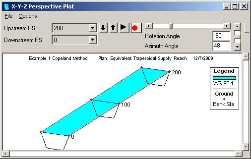
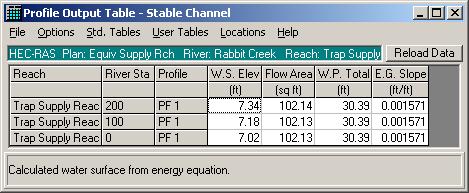
39 Trapezoidal Channel Supply Reach 39


40 Stable Channel Design Function 40

41 Compute 41

42 Select Design Channel for b = 20 ft 20 FT 20 FT 42
43 Stability Curve, Width vs. Slope ppm ppm 43
44 Gravel/Cobble Beds HEC-RAS Sediment Transport Capacity Function 44
45 HR Sediment Transport Capacity (STC) Grain size classes are input as grain size and percent finer. Computes STC for each size class, g si Total STC is computed by the equation g s,total = p i g si where p i = fraction of size class i in the bed. Can compute the total STC for all six Sediment Transport Potential functions. 45
46 Gravel/Cobble Example The stream has the following bank-full conditions Water surface elevation = 11.7 feet Discharge = 3,100 cfs Slope = Elevation (ft) Elevation (ft) Station Station (ft) (ft) Sta-Elev Sta-Elev Bankfull Bankfull Elevation Elevation Movable Movable Bed Bed
47 Pebble Count for Gravel/Cobble Stream INCHES PARTICLE MILLIMETER SIZE CLASS COUNT % CUM % D top (mm) Silt/Clay < S/C Very Fine S Fine A Medium N Coarse D Very Coarse S Very Fine Fine G Fine R Medium A Medium V Coarse E Coarse L Very Coarse S Very Coarse Small C Small O L Large B E Large B S Small B D Small O E Medium U R Lrg to Very Lrg L S BEDROCK BDRK NOTE 47
48 Log-probability plot of Bed Material Sand Gravel Cobble 48


49 Make New HEC-RAS Model with one cross section and no discharge 49
50 Uniform Flow Bed uses Limerinos, banks use Manning (T&E gives n bank = 0.077) 50
51 Uniform Flow Bed uses Mannings, Banks use n = (T&E gives n bed = ) 51


52 Create and Run Natural Supply Reach 52
53 Sediment Transport Capacity Function LOB Input Grain Sizes (Fake size for banks) Main ROB Diam, mm % Finer Diam, mm % Finer Diam, mm % Finer

54 Compute, Sediment Rating Curve Plot, Generate Report 54
55 Select All Grains Sizes to see a more detailed Report Bed Material Fraction by Standard Grade Size A-W E-H Laur MPM Toff Yang Bed Material Fraction by Standard Grade Size A-W E-H Laur MPM Toff Yang Class dm (mm) Left Main Right (tons/day) (tons/day) (tons/day) (tons/day) (tons/day) (tons/day) Class dm (mm) Left Main Right (tons/day) (tons/day) (tons/day) (tons/day) (tons/day) (tons/day) All Grains All Grains

56 Meyer-Peter Mueller Function Results
57 Design 1 (b = 35 ft, m = 3:1 hor: vert) Assume slope Create 3 cross section model with trapezoidal xsecs with same n s n s and Q as supply reach Run steady flow model Run Sediment Transport Capacity function See if STC equals 1083 tons/day if not back to the top with a new slope 57
58 Design 1 (b = 35 ft, m = 3:1 hor: vert) T & E gives S = T & E gives S = S = = S = = b b = = Natural Natural Design Design b = 35 Natural Design Nat/Des b = 35 Natural Design Function tons/day Nat/Des Nat/Des Function tons/day Nat/Des Function tons/day Function tons/day A-W A-W NA NA A-W A-W NA NA E-H E-H E-H E-H Laur Laur NA NA Laur Laur MPM MPM MPM MPM Toff Toff Toff Toff Yang Yang Yang Yang S = = S = = b b = = Natural Natural Design Design b = 35 Natural Design Nat/Des b = 35 Natural Design Function tons/day Nat/Des Nat/Des Function tons/day Nat/Des Function tons/day Function tons/day A-W A-W A-W A-W NA NA E-H E-H E-H E-H Laur Laur Laur Laur MPM MPM MPM MPM Toff Toff Toff Toff Yang Yang Yang Yang


59 Final Design 59
60 Design 2 - Select slope and side slopes, find b S = , m = 2.5:1 hor: vert b b = = STC STC in in Tons/Day Tons/Day bnk bnk ht ht = = S S = = m = = Function Function All All Grains Grains RS RS 0 0 RS RS RS RS A-W A-W Station Station Elevation Elevation Station Station Elevation Elevation Station Station Elevation Elevation E-H E-H Laur Laur MPM MPM Toff Toff Yang Yang
61 S = , m = 2.5:1 hor: vert b = 15 ft, bank ht = ft Design Design Channel, Channel, b = 15', 15', hor:vert hor:vert = 2.5:1, 2.5:1, S = Elevation Elevation (ft) (ft) Station Station (ft) (ft) Design Design Channel Channel Bankfull Bankfull Elevation Elevation Movable Movable Bed Bed 61
62 Elevation Elevation (ft) (ft) Design 3 - S = , m = 2.5:1 hor: vert b = 76 ft, bank ht = 8.73 ft Station Station (ft) (ft) Design Design Channel Channel Bankfull Bankfull Elevation Elevation Movable Movable Bed Bed 4 4 b b = = MPM Gs (Tons/day) = Final Final Design Design 2 2 bnk bnk ht ht = = S S = = m = = Tons/day Tons/day RS RS 0 0 RS RS RS RS Function Function All All Grains Grains Station Station Elevation Elevation Station Station Elevation Elevation Station Station Elevation Elevation A-W A-W E-H E-H Laur Laur MPM MPM Toff Toff Yang Yang MPM Gs (Tons/day) = Final Design 3 62
63 Sidewall Correction Method W d n w A w /2 m d y d A A w /2 b A b 1 1 m d b d n b m d n w square } 4/3 2/3 1/2 2 A 2 4/3 1 1 Metric version of Manning ' s Equation V = R S V = S n n P Einstein assumed V and S are constant in bank area and sidewall area constant /3 2 3/4 3/4 2 3/4 V 1 A V 1 A 1 A V = 2 4/3 = 2 = 3/2 S n P S n P n P S 3/2 P Constant 3/2 Pw 3/2 Pb n = nw = nb = β A A A w b P P P A= A + A n = n + n n P= n P + n P β β β 3/2 3/2 w 3/2 b 3/2 3/2 3/2 w b w b w w b b 2/3 3/2 3/2 1 n P n P n = n P + n P also A = A and A = A 3/2 3/2 P n P n P 3/2 3/2 w w b b ( w w b b) w ( ) b ( ) 63
64 Sidewall Example 1 2 S = n w = n = w = n b = P = ft P = + = ft P= P + P = ft 2 2 b 50 ; w b w 72.4 (5)(10) A = 50*5 = 250 ft ; A = 2 = 50 ft A = A + A = 300 ft rect tria rect tria 2/3 2/3 1 3/2 3/2 1 3/2 3/2 n= ( nw Pw + nb Pb) = ((0.040) (0.025) 50) P 72.4 n = Q = 1.49 (300) (72.4) 5/3 2/ / (0.040) 22.4 (0.025) 50 Aw = = ft and A = = ft (0.030) 72.4 (0.030) /2 3/2 2 2 ( 300) 143 3/2 b 3/2 ( 300) 157 Geometric values A = 50 ft and A = 250 ft w = ft s 2 2 b 64
65 ARR Analytical Method W d n w y d n d = Manning s 1 composite n 1 m d m d b d n b m d n w 1.49 A Manning for Design Channel Qd = Sd ARR Eq.4 2 n P ( s ) ( ) 5/3 d 2/3 d 8b 3/2 MPM B = γys ( γs γ) d50 ARR Eq. 4 6 ρ y S G 1 d = =.4 8 m m 50 Bm Bd bd bm ARR Eq yd Sd Gs 1 d50 Given Q, m, n, S = S, G = 2.65, d, b and y. d d d m d s 50 m m Use iteration to solve Eqs.4 2and 4 8for b and y by iteration d Subscripts d and m denote design channel and match reach channels, respectively. d 3/2 d 65
66 ARR vs HEC-RAS Composite n from HEC-RAS Supply Reach ) ARR solution for Design 1 ( HR solution b d = 35 ft) d m (mm) ) ARR solution for Design 1 ( HR solution b d = 35 ft) d m (mm) m d = 3 S d = n d = m d = 3 S d = n d = y d b d A d P d W b Q b ΔQ y d b d A d P d W b Q b ΔQ b HR = 35 ft b ARR = 42.9 ft b HR /b ARR = 0.82 ) ARR solution for Design 2 ( HR solution b d = 15 ft) d m (mm) ) ARR solution for Design 2 ( HR solution b d = 15 ft) d m (mm) m d = 2.5 S d = n d = m d = 2.5 S d = n d = y d b d A d P d W b Q b ΔQ y d b d A d P d W b Q b ΔQ b HR = 15 ft b ARR = 22.8 ft b HR /b ARR = 0.66 ) ARR solution for Design 3 ( HR solution b d = 76 ft) d m (mm) ) ARR solution for Design 3 ( HR solution b d = 76 ft) d m (mm) m d = 2.5 S d = n d = m d = 2.5 S d = n d = y d b d A d P d W b Q b ΔQ y d b d A d P d W b Q b ΔQ ARR did not converge b HR = 76 ft b ARR = 58.8 ft b HR /b ARR =
67 ARR vs HEC-RAS Composite n values from HR Design Reaches (b) ARR solution for Design 1 ( HR solution b d = 35 ft) m d = 3 S d = n d = d m (mm) = 22.6 y d b d A d P d W b Q b ΔQ n = b HR = 35 ft b ARR = 33.2 ft b HR /b ARR = 1.05 (c) ARR solution for Design 2 ( HR solution b d = 15 ft) m d = 2.5 S d = n d = d m (mm) = 22.6 y d b d A d P d W b Q b ΔQ (d) ARR solution for Design 3 ( HR solution b d = 76 ft) ft) m d = 2.5 S d = n d = d m (mm) = 22.6 y d b d A d P d W b Q b ΔQ n = b HR = 15 ft b ARR = 17.8 ft b HR /b ARR = 0.84 ARR did not converge n = b HR = 76 ft b ARR = 58.8 ft b HR /b ARR =
68 ARR s s Simplified MPM Equation ARR simplified MPM equation 1 y d 8b } 3/2 B= ( RKR) γ R S γ γ d ρ ( ) }50 b s m 3/2 Meyer Peter Mueller ( MPM ) 8b B= RKR R S ( ) d ρ ' b b 3/2 ( ) γ b γs γ m ' n b RKR = = Nikuradse roughness ratio nb n n = Manning coefficient for grain size = total Manning coefficient 3/2 68
69 Conclusions McEnroe s s KAM and ARR methods provide very useful tools and should serve as references for all stable channel design projects. It is recommended that HEC-RAS be used in lieu of the analytical approaches of KAM and ARR if the grain size distribution is known for an alluvial channel. If the grain size distribution is unknown or if the channel has a cohesive bed, the KAM and ARR methods should be used in their entirety. The HEC-RAS methods reported herein only provide for design of the riffle cross section and do not include help for planform design aspects. The methods outlined in McEnroe s s reports should be used for the overall stream design. They provide guidance for the design of meanders, riffle pool spacing and pool dimensions. 69
70 Analysis of Bed Grain Size Distribution Sieve Analysis Visual-Accumulation Tube Pebble Count 70
71 Log-normal Distribution Probability Density Function PDF 1 1 log d log d f(log d) exp σlog d 2π 2 σ log d Cumulative Distribution Function CDF σ g 50 = 84.1 log σ log d d15.9 = = = log d d F(log d) = f(log d) d(log d) = P/100 StandardDeviation d d d d 1 1 d σ log d = (log d84.1 log d15.9 ) = log = log 2 2 d Geometric standard deveiation d d σ g 84.1 log σ log d d15.9 = = = d d d d d
72 Standardized Random Variable Mean = 0, standard deviation =1 2 log d log d 1 z = ( ) = exp 2π 2 50 z PDF f z σ log d z CDF F( z) = f ( z) dz where F( z) = 1 F( z) F(z) for Standard Normal Random Variable z F(z) for Standard Normal Random Variable z z z
73 Example - Sand Bed Material 73
74 Log-Probability Plot of Sand Bed Data Cumulative Distribution Function Expressed as a probability (%) d 84 =0.363 mm d (mm) d 50 =0.232 mm d 16 =0.158 mm σ σ d log d g 65 d = = = d log log = = ( ) ( ) 0.386σ + log d log = = = = log d mm 74
75 Log Probability Plot using NORMSINV Function in EXCEL -0.2 d 15.9 d 50 d 84.1 log(d 84 ) log(d 84 ) log(d 50 ) log(d 50 ) log(d 16 ) log(d 16 ) log 10 (d) NORMSINV(P/100) 75
76 NORMSINV and NORMSDIST EXCEL Functions d 50 = 0.48 mm log 10 (d 50) = d 50 = 0.48 mm log 10 (d 50) = σ g = 1.28 mm log 10 (σ g) = σ g = 1.28 mm log 10 (σ g) = log( di ) log( d50) zi = log( di ) log( d50) zi = log log ( ( σ g σ ) ) d d = = i i log ( d ) + z log ( σ ) ( ) ( ) 50 i g 10 log d50 + zilog σ g 10 g P (% finer) F(z) z=normsinv(f) d i (mm) F(z)=NORMSDIST(z) P (% finer) F(z) z=normsinv(f) d i (mm) F(z)=NORMSDIST(z) d 20 = d 20 = d 40 = d 40 = d 60 = d 60 = d 80 = d 80 = d = d = d 50 = d 50 = log( di ) log( d50) zi = log( di ) log( d50) zi = log log ( ( σ g σ ) ) g d i (mm) z F(z)=NORMSDIST(z) P (% finer) d i (mm) z F(z)=NORMSDIST(z) P (% finer)
77 Geometric Standard Deviation ( d84 d50 ) ( d50 d16 ) ( d d ) ( d d ) ( d d ) ( d d ) 2 logσ = log log + log log ( ) ( ) ( ) 2 logσ = log / + log / = log / logσ = log ( d / d ) logσ = log ( d / d ) = log d / d 2 σ = / d logσ = log d log d σ = d / d logσ top d Alternative Method in HEC bot RAS Manual top = log d log d σ = d / d bot d d σ = σ 0.5( ) ave = σtop + σbot = d d
78 Geometric Standard Deviation when P i for smallest sample d is greater than 0.16 Let P i = the lowest percent finer from the pebble count analysis and let z i = the standardized normal variable that gives F(z) = P i /100. ( 84 P ) (1 z)logσ = log d log d logσ σ ( log 84 log P ) = = = 1 (1 z) d 84 = d P 1 1 d log d d d d log (1 z) (1 z) d P (1 z) P 78
79 1 Example for Smallest d > d 16 Given d = 8mm and d = 2mm P = 32 F( z) = 0.32 F( z) = 1 F( z) = = 0.68 z = z = σ (1 z) d (1 ( )) = = = = 84 log d50 log d84 log 2.04 log 2.04 d 50 d P d = = d = = = 2.79 mm ( 79
80 Pebble Count for Gravel/Cobble Stream Sand Gravel Cobble 80
81 L A SOIL PARTICLES PORES Theoretical Justification for Pebble Count porosity = V / V ; A = na; V = A( x) dx pores total pores pores pores 0 As = (1 n) A = area of A occupied by soil Ai = area of A occupied by particles of a specified size range fi = Ai / As Wi γ svi Vi Vi pi = = = = W γ V V (1 n) V p p p i i i s, total s s, total s, total total L L L L i i ( i s) ( i[ (1 ) ]) A dx A dx f A dx p n A dx = = = = (1 nv ) (1 n) AL (1 n) AL (1 n) AL L total ( i[ ]) L f (1 n) A dx fi (1 n) Adx 0 0 fi (1 n) AL = = = (1 nal ) (1 nal ) (1 nal ) = f i Actual Pebble Count Shielding, settling, etc. Actual Pebble Count Shielding, settling, etc. L 81
82 Mixed Sand and Gravel Beds Watershed Institute, Inc. Pebble Count Data log10(d) log10(d) MT043442RR01 MT043442RR01 d D16 dd50 d D84 3 d D16 dd50 d D D d (mm) 0.5 D d (mm) 0.5 dd dd D -0.5 d dd dd dd normsinv(p/100) normsinv(p/100) Pebble Count Data D16 D50 D84 Extrapolated Pebble Count Data D16 D50 D84 Extrapolated log10(d) log10(d) SN321115RR SN321115RR dd16 dd50 dd84 3 dd16 dd50 dd d D (mm) 0 d D (mm) -1 dd dd 16 D d D dd d dd normsinv(p/100) normsinv(p/100) Pebble Count Data D16 D50 D84 Extrapolated Pebble Count Data D16 D50 D84 Extrapolated 82
83 Mixed Sand and Gravel Beds (cont.) W finer (gm) W finer (gm) Sand Gravel Sand Gravel Dd Dd σ g W σ g (gm) W (gm) Two Bed Materials Two Bed Materials log D log 10 (d) D log 10 (d) Gravel Sand Gravel Sand log log D log 10 D (d) log 10 (d) Two Bed Materials Two Bed Materials 3 3 Sand 2.5 Sand Gravel Gravel Sand 2.5 Dd Sand Gravel Gravel 10 2 Dd 50 σ g σ 1.5 W g (gm) W (gm) NORMINV(P/100) norminv(p/100) NORMINV(P/100) norminv(p/100) Sand Gravel Sand Gravel 83
84 Mixed Sand and Gravel Beds (cont.) W Finer (gm) W Finer (gm) Combined Combined Sand SandGravel Gravel 90 Sand SandGravel Gravel D dd σ g d σ W (gm) g g W (gm) σ g W (gm) W (gm) log D log D log log 10 (d) 10 (d) Combined Combined log log 10 (d) 10 (d) log D log D Sand SandGravel Gravel Sand SandGravel Gravel D dd σ g d σ W (gm) g g W (gm) σ g W (gm) W (gm) log D 50 D 50-1 log 10 (d 50 ) d 50 (mm) log log D 50 D (d ) d (mm) norminv(p/100) norminv(p/100) 84
3 Theoretical Basis for SAM.sed Calculations
 3 Theoretical Basis for SAM.sed Calculations Purpose Sediment transport functions can be used to calculate the bed material portion of the sediment discharge rating curve. This rating curve can then be
Technical Memorandum. To: From: Copies: Date: 10/19/2017. Subject: Project No.: Greg Laird, Courtney Moore. Kevin Pilgrim and Travis Stroth
 Technical Memorandum To: From: Greg Laird, Courtney Moore Kevin Pilgrim and Travis Stroth 5777 Central Avenue Suite 228 Boulder, CO 80301 www.otak.com Copies: [Electronic submittal] Date: 10/19/2017 Subject:
Sediment and Erosion Design Guide
 Sediment and Erosion Design Guide Sediment Transport & Bulking Factors Goals of this Session Review key principals Review basic relationships and available tools Review bulking factor relationships Purposes
Mangyeong River Hydraulic Modeling Analysis
 Mangyeong River Hydraulic Modeling Analysis Draft Prepared For: Korea Institute of Construction Technology, Republic of Korea by: Dr. Pierre Y. Julien Jaehoon Kim Colorado State University Engineering
* Chapter 9 Sediment Transport Mechanics
 Chapter 9 Sediment Transport Mechanics Section I Introduction 9-1. Definition Sedimentation embodies the processes of erosion, entrainment, transportation, deposition, and compaction of sediment. These
Field Methods to Determine/ Verify Bankfull Elevation, XS Area & Discharge
 Module # 6 Field Methods to Determine/ Verify Bankfull Elevation, XS Area & Discharge Iowa s River Restoration Toolbox Level 1 / Base Training Overview of Basic Field Data Collection Site Map Cross Sections
Fish Passage at Road Crossings
 Fish Passage at Road Crossings 1 Crossing Design Workshop Outline 1:00 to 2:00 Intro, Design Overview, Channel Width 2:00 to 2:15 Break 2:15 to 3:15 No-Slope, Stream Simulation Design 3:15 to 3:30 Break
Water quality needs: Flow, velocity. Fish biologists need: Critical depth or velocity. Hydrology gives flows m 3 /s or day
 Environmental Water Allocation Hydraulics Dr L Beevers Heriot Watt University, it UK l.beevers@hw.ac.uk Overview Why hydraulics in EWA? Different types of flows Theory Case studies Review Why do we need
Geomorphology Geology 450/750 Spring Fluvial Processes Project Analysis of Redwood Creek Field Data Due Wednesday, May 26
 Geomorphology Geology 450/750 Spring 2004 Fluvial Processes Project Analysis of Redwood Creek Field Data Due Wednesday, May 26 This exercise is intended to give you experience using field data you collected
Ways To Identify Background Verses Accelerated Erosion
 Ways To Identify Background Verses Accelerated Erosion Establish Background Condition From Old Ground Photos, Aerial Photos, and Maps Compare Rate Over Time At the Same Location, or for Reaches Channel
OBJECTIVES. Fluvial Geomorphology? STREAM CLASSIFICATION & RIVER ASSESSMENT
 STREAM CLASSIFICATION & RIVER ASSESSMENT Greg Babbit Graduate Research Assistant Dept. Forestry, Wildlife & Fisheries Seneca Creek, Monongahela National Forest, West Virginia OBJECTIVES Introduce basic
Fluvial Geomorphology
 Geomorphic Components of Riparian Ecosystems W. Barry Southerland, Ph.D. Fluvial Geomorphologist, CPESC #514 West National Technology Support Center Water Quality and Quantity Technology Development Team
EXAMPLES (SEDIMENT TRANSPORT) AUTUMN 2018
 AUTUMN 2018") EXAMPLES (SEDIMENT TRANSPORT) AUTUMN 2018 Q1. Using Cheng s formula estimate the settling velocity of a sand particle of diameter 1 mm in: (a) air; (b) water. Q2. Find the critical Shields parameter diameter
EXAMPLES (SEDIMENT TRANSPORT) AUTUMN 2018 Q1. Using Cheng s formula estimate the settling velocity of a sand particle of diameter 1 mm in: (a) air; (b) water. Q2. Find the critical Shields parameter diameter
CONCEPTS Conservational Channel Evolution and Pollutant Transport System
 CONCEPTS Conservational Channel Evolution and Pollutant Transport System Eddy J. Langendoen Watershed Physical Processes Research Unit National Sedimentation Laboratory USDA Agricultural Research Service
GEOL 652. Poudre River Fieldtrip
 GEOL 652. Poudre River Fieldtrip One of the more difficult variables to measure and/or estimate when studying flow in natural channels is that of roughness. Roughness, usually approximated with Manning
Stable Channel Analysis and Design
 PDHonline Course H145 (4 PDH) Stable Channel Analysis and Design Instructor: Joseph V. Bellini, PE, PH, DWRE, CFM 2012 PDH Online PDH Center 5272 Meadow Estates Drive Fairfax, VA 22030-6658 Phone & Fax:
Restoration Modeling Analysis for Abandoned Channels of the Mangyeong River
 1) 한국환경과학회지제20권 ( 제5호 ), 555~564, 2011 Journal of the Environmental Sciences DOI: 10.5322/JES.2011.20.5.555 Restoration Modeling Analysis for Abandoned Channels of the Mangyeong River Jaehoon Kim, Pierre
Tom Ballestero University of New Hampshire. 1 May 2013
 Tom Ballestero University of New Hampshire 1 May 2013 1 Hydrology 2 Basic Hydrology Low flows most common Flows that fill the stream to the banks and higher are much less common Filling the stream to the
Calculation of Stream Discharge Required to Move Bed Material
 Calculation of Stream Discharge Required to Move Bed Material Objective: Students will map two sections of a stream and calculate the depth, velocity, and discharge of flows required to move the stream
!"#$%&&'()*+#$%(,-./0*)%(!
*+#$%(,-./0*)%(!") 8:30 Sign in Hoosic River Revival Coalition!"#$%&&'()*+#$%(,-./0*)%(! 12-#30+4/#"5-(60 9:00 Welcome and Introductions 9:15 Goals for Today s Program: A Description of the Planning Process 9:30 First Session:
8:30 Sign in Hoosic River Revival Coalition!"#$%&&'()*+#$%(,-./0*)%(! 12-#30+4/#"5-(60 9:00 Welcome and Introductions 9:15 Goals for Today s Program: A Description of the Planning Process 9:30 First Session:
Uniform Channel Flow Basic Concepts. Definition of Uniform Flow
 Uniform Channel Flow Basic Concepts Hydromechanics VVR090 Uniform occurs when: Definition of Uniform Flow 1. The depth, flow area, and velocity at every cross section is constant 2. The energy grade line,
MATHEMATICAL MODELING OF FLUVIAL SEDIMENT DELIVERY, NEKA RIVER, IRAN. S.E. Kermani H. Golmaee M.Z. Ahmadi
 JOURNAL OF ENVIRONMENTAL HYDROLOGY The Electronic Journal of the International Association for Environmental Hydrology On the World Wide Web at http://www.hydroweb.com VOLUME 16 2008 MATHEMATICAL MODELING
Sediment transport and river bed evolution
 1 Chapter 1 Sediment transport and river bed evolution 1.1 What is the sediment transport? What is the river bed evolution? System of the interaction between flow and river beds Rivers transport a variety
NATURE OF RIVERS B-1. Channel Function... ALLUVIAL FEATURES. ... to successfully carry sediment and water from the watershed. ...dissipate energy.
 1 2 Function... Sevier River... to successfully carry sediment and water from the watershed....dissipate energy. 3 ALLUVIAL FEATURES 4 CHANNEL DIMENSION The purpose of a stream is to carry water and sediment
Determining the Suitable Sediment extraction Locations of Existing Sand and Gravel Mines on Boshar River in Iran using HEC-RAS Modeling
 ICSE6-134 Determining the Suitable Sediment extraction Locations of Existing Sand and Gravel Mines on Boshar River in Iran using HEC-RAS Modeling Mohammad GHARESIFARD 1, Ali JAHEDAN 2, Bahar MOLAZEM 3
Vegetation effects on river hydraulics. Johannes J. (Joe) DeVries David Ford Consulting Engineers, Inc. Sacramento, CA
 DeVries David Ford Consulting Engineers, Inc. Sacramento, CA") Vegetation effects on river hydraulics Johannes J. (Joe) DeVries David Ford Consulting Engineers, Inc. Sacramento, CA jjdevries@ford-consulting.com SAC05 D2P31 RM 99.0L VIEW UPSTREAM AT UPSTREAM END DWR
Vegetation effects on river hydraulics Johannes J. (Joe) DeVries David Ford Consulting Engineers, Inc. Sacramento, CA jjdevries@ford-consulting.com SAC05 D2P31 RM 99.0L VIEW UPSTREAM AT UPSTREAM END DWR
Aquifer an underground zone or layer of sand, gravel, or porous rock that is saturated with water.
 Aggradation raising of the streambed by deposition that occurs when the energy of the water flowing through a stream reach is insufficient to transport sediment conveyed from upstream. Alluvium a general
Open Channel Flow Part 2. Ch 10 Young, notes, handouts
 Open Channel Flow Part 2 Ch 10 Young, notes, handouts Uniform Channel Flow Many situations have a good approximation d(v,y,q)/dx=0 Uniform flow Look at extended Bernoulli equation Friction slope exactly
Session C1 - Applying the Stream Functions Pyramid to Geomorphic Assessments and Restoration Design
 University of Massachusetts - Amherst ScholarWorks@UMass Amherst International Conference on Engineering and Ecohydrology for Fish Passage International Conference on Engineering and Ecohydrology for Fish
What discharge (cfs) is required to entrain the D 84 (84 th percentile of sediment size distribution) in Red Canyon Wash?
 is required to entrain the D 84 (84 th percentile of sediment size distribution) in Red Canyon Wash?") Gregory Indivero 31 October 2011 What discharge (cfs) is required to entrain the D 84 (84 th percentile of sediment size distribution) in Red Canyon Wash? What discharge was required to deposit observed
Gregory Indivero 31 October 2011 What discharge (cfs) is required to entrain the D 84 (84 th percentile of sediment size distribution) in Red Canyon Wash? What discharge was required to deposit observed
GLG598 Surface Processes and Landform Evolution K. Whipple VERDE RIVER: FLOW MECHANICS, ROUGHNESS, AND SHEAR STRESS
 VERDE RIVER: FLOW MECHANICS, ROUGHNESS, AND SHEAR STRESS This lab will introduce you to some common field techniques and some general understanding of the geomorphic processes operating in a stream. The
GLG598 Surface Processes and Landform Evolution K. Whipple Fall 2012 VERDE RIVER: FLOW MECHANICS, ROUGHNESS, AND SHEAR STRESS
 VERDE RIVER: FLOW MECHANICS, ROUGHNESS, AND SHEAR STRESS This lab will introduce you to some common field techniques and some general understanding of the geomorphic processes operating in a stream. The
Do you think sediment transport is a concern?
 STREAM RESTORATION FRAMEWORK AND SEDIMENT TRANSPORT BASICS Pete Klingeman 1 What is Your Restoration Project Like? k? Do you think sediment transport is a concern? East Fork Lewis River, WA Tidal creek,
International Journal of Scientific & Engineering Research, Volume 6, Issue 3, March ISSN
 International Journal of Scientific & Engineering Research, Volume 6, Issue 3, March-2015 1338 Modeling of Sediment Transport Upstream of Al- Shamia Barrage Prof. Dr. Saleh I. Khassaf, Mohammed jaber Abbas
PENNSYLVANIA DEPARTMENT OF TRANSPORTATION ENGINEERING DISTRICT 3-0
 PENNSYLVANIA DEPARTMENT OF TRANSPORTATION ENGINEERING DISTRICT 3-0 LYCOMING COUNTY S.R.15, SECTION C41 FINAL HYDROLOGIC AND HYDRAULIC REPORT STEAM VALLEY RUN STREAM RELOCATION DATE: June, 2006 REVISED:
May 7, Roger Leventhal, P.E. Marin County Public Works Laurel Collins Watershed Sciences
 May 7, 2013 Roger Leventhal, P.E. Marin County Public Works Laurel Collins Watershed Sciences Background Funded in 2009 under EPA 2100 Grant for $30k and managed by SFEP Project Goals: Update original
Beaver Creek Corridor Design and Analysis. By: Alex Previte
 Beaver Creek Corridor Design and Analysis By: Alex Previte Overview Introduction Key concepts Model Development Design Accuracy Conclusion Refresh v = Beaver Creek Site = Wittenberg Introduction Low head
The Importance of Riparian Vegetation in Channel Restoration: Moving Towards Quantification in Design
 The Importance of Riparian Vegetation in Channel Restoration: Moving Towards Quantification in Design Rob Millar Department of Civil Engineering The University of British Columbia "Nothing is as practical
STREAM MODULES: SPREADSHEET TOOLS FOR RIVER EVALUATION, ASSESSMENT AND MONITORING **
 STREAM MODULES: SPREADSHEET TOOLS FOR RIVER EVALUATION, ASSESSMENT AND MONITORING ** D. E. Mecklenburg 1, A. Ward 2 Abstract Stream physical condition is increasingly a priority for resource managers.
APPLICATION OF HEC-RAS MODEL FOR ESTIMATING CHANGES IN WATERCOURSE GEOMETRY DURING FLOODS
 Studia Geotechnica et Mechanica, Vol. XXXIV, No. 2, 2012 DOI: 105277/sgm021206 APPLICATION OF HEC-RAS MODEL FOR ESTIMATING CHANGES IN WATERCOURSE GEOMETRY DURING FLOODS JOANNA MARKOWSKA Department of Environmental
Stream Classification
 Stream Classification Why Classify Streams? Communication Tool Describe Existing Conditions & Trends Describe Restoration Goals Research Tool Morphologic Stream Classification Systems Schumm (1977) Alluvial
CHAPTER 2- BACKGROUND. INVESTIGATIONS OF COMPOSITE ROUGHNESS COEFFICIENT IN A RIVER WITH LOW FLOW
 2. Background 2.1 Introduction The estimation of resistant coefficient and hence discharge capacity in a channel or river is one of the fundamental problems facing river engineers. When applying Manning
~ W 89 CONTENTS J-1 J-1 J-6 J-7 J-9 J-10 J-10 J-10
 15 W 89 J-1. J-2. J-3. J-4. J-5. J-6 J-7. J-8. CONTENTS Introduction... Stable Slope Method... Example 1... Armor Bed Method... Example 2...*.... Dominant Discharge... Bed Material Gradation... Numerical
APPENDIX B Hydraulic Considerations for Pipeline Crossings of Stream Channels
 APPENDIX B Hydraulic Considerations for Pipeline Crossings of Stream Channels B-1 B-2 APPENDIX B HYDRAULIC CONSIDERATIONS FOR PIPELINE CROSSINGS OF STREAM CHANNELS Pipeline crossings of perennial, intermittent,
Alluvial Channel Design
 United States Department of Agriculture Natural Resources Conservation Service Stream Restoration Design Chapter 9 Issued August 2007 Cover photo: In an alluvial channel, there is a continual exchange
Uniform Channel Flow Basic Concepts Hydromechanics VVR090
 Uniform Channel Flow Basic Concepts Hydromechanics VVR090 ppt by Magnus Larson; revised by Rolf L Feb 2014 SYNOPSIS 1. Definition of Uniform Flow 2. Momentum Equation for Uniform Flow 3. Resistance equations
Estimating Scour. CIVE 510 October 21 st, 2008
 Estimating Scour CIVE 510 October 21 st, 2008 1 Causes of Scour 2 Site Stability 3 Mass Failure Downward movement of large and intact masses of soil and rock Occurs when weight on slope exceeds the shear
Geomorphology 5. Stream Sediment Stream Sediment
 Geomorphology 5. Stream Sediment 1 Name 47 Points LEARNING OUTCOMES 5. Stream Sediment By the end of this assignment you should be able to: Describe the relationship between particle size and critical
 1.3.1.1 Incipient Motion Particle movement will occur when the instantaneous fluid force on a particle is just larger than the instantaneous resisting force related to the submerged particle weight and
* Chapter 10 Nonequilibrium Sediment Transport
 Chapter 10 Nonequilibrium Sediment Transport Section I Introduction 10-1. General Nonequilibrium sediment transport refers to cases where the outflowing sediment discharge from a reach does not equal the
7.3 Sediment Delivery Analysis
 7.3 Sediment Delivery Analysis In order to evaluate potential changes in sedimentation patterns that could occur due to impacts from the FCP and LPP alignments, sediment assessment models were constructed
Sediment Transport Analysis for Stream Restoration Design: The Good, the Bad, and the Ugly.
 Sediment Transport Analysis for Stream Restoration Design: The Good, the Bad, and the Ugly. Brett Jordan Phd, PE HydroGeo Designs LLC. Land and Water Services Inc. THE GOOD THE BAD THE UGLY THE GOOD THE
How to Design Bendway Weirs
 How to Design Bendway Weirs Project Background U.S. Bureau of Reclamation: Middle Rio Grande Channel Maintenance Program 29-Mile Study Reach: Cochiti Dam to Bernalillo Geomorphic Changes Due to Dam Construction
Riparian Assessment. Steps in the right direction... Drainage Basin/Watershed: Start by Thinking Big. Riparian Assessment vs.
 Riparian Assessment vs. Monitoring Riparian Assessment What is a healthy stream? Determine stream/riparian health Determine change or trend, especially in response to mgmt Classification = designation
Sediment Sampling and Analysis for Stream Restoration Projects
 Sediment Sampling and Analysis for Stream Restoration Projects by Craig Fischenich 1 and Charlie Little 2 September 2007 Complexity Low Moderate High Value Low Moderate High Cost Low Moderate High OVERVIEW
Vermont Stream Geomorphic Assessment. Appendix E. River Corridor Delineation Process. VT Agency of Natural Resources. April, E0 - April, 2004
 Vermont Stream Geomorphic Assessment Appendix E River Corridor Delineation Process Vermont Agency of Natural Resources - E0 - River Corridor Delineation Process Purpose A stream and river corridor delineation
A STUDY OF LOCAL SCOUR AT BRIDGE PIERS OF EL-MINIA
 A STUDY OF LOCAL SCOUR AT BRIDGE PIERS OF EL-MINIA Dr. Gamal A. Sallam 1 and Dr. Medhat Aziz 2 ABSTRACT Bridges are critical structures that require a substantial investment to construct and serve an important
(3) Sediment Movement Classes of sediment transported
 Sediment Movement Classes of sediment transported") (3) Sediment Movement Classes of sediment transported Dissolved load Suspended (and wash load ) Important for scouring algae Bedload (5-10% total load Moves along bed during floods Source of crushing for
(3) Sediment Movement Classes of sediment transported Dissolved load Suspended (and wash load ) Important for scouring algae Bedload (5-10% total load Moves along bed during floods Source of crushing for
Module 2. The Science of Surface and Ground Water. Version 2 CE IIT, Kharagpur
 Module The Science of Surface and Ground Water Lesson Sediment Dynamics in Alluvial Rivers and Channels Instructional Objectives On completion of this lesson, the student shall be able to learn the following:.
Application of Fluvial Geomorphologic Techniques At Abandoned Mine Sites 1. David A. Greenfield 2 Dennis M. Palladino 3
 Application of Fluvial Geomorphologic Techniques At Abandoned Mine Sites 1 David A. Greenfield 2 Dennis M. Palladino 3 ABSTRACT Watersheds that have been severely impacted by mining can no longer transport
Coarse Sediment Augmentation on Regulated Rivers. Scott McBain McBain & Trush, Inc.
 Coarse Sediment Augmentation on Regulated Rivers Scott McBain McBain & Trush, Inc. scott@mcbaintrush.com Components Some geomorphic and ecological considerations Conceptual approach at understanding augmentation
Summary of Hydraulic and Sediment-transport. Analysis of Residual Sediment: Alternatives for the San Clemente Dam Removal/Retrofit Project,
 Appendix N SUMMARY OF HYDRAULIC AND SEDIMENT-TRANSPORT ANALYSIS OF RESIDUAL SEDIMENT: ALTERNATIVES FOR THE SAN CLEMENTE DAM REMOVAL/RETROFIT PROJECT, CALIFORNIA the San Clemente Dam Removal/Retrofit Project,
BED LOAD SEDIMENT TRANSPORT
 BED LOAD SEDIMENT TRANSPORT Kamal EL KADI ABDERREZZAK EDF-R&D, Laboratoire National d Hydraulique et Environnement (LNHE) 1 17-19 September 2009 UNL, Santa Fe, Argentina OUTLINE I. Bed load II. Settling
Avoiding Geohazards in the Mid-Atlantic Highlands by Using Natural Stream Principles
 Avoiding Geohazards in the Mid-Atlantic Highlands by Using Natural Stream Principles J. Steven Kite, WVU Neal Carte, WVDOT Will Harman, Michael Baker Corp. Donald D. Gray, WVU Photo: W. Gillespie North
Squaw Creek. General Information
 General Information is a tributary to the Salmon River. It enters the north side of the river about 0 miles downstream of North Fork, Idaho. The study reach is about a 30 ft length of stream about 2 miles
Design and Construction
 Design and Construction Stream Simulation With power point slides shamelessly stolen from: Forest Service AOP Training Course Bob Gubernick Paul Anderson John Kattell USDA Forest Service Interim Directive
Appendix E Rosgen Classification
 Appendix E Stream Type s Using the morphometric parameters described above, stream reaches are classified into 7 major stream types (Aa+ through G) based on s (1996) criteria. The relevant stream classifications
An Adaptive Assessment of the Flushing Flow Needs of the Lower Poudre River, Colorado: First Evaluation
 Hydrology Days 29 An Adaptive Assessment of the Flushing Flow Needs of the Lower Poudre River, Colorado: First Evaluation 1 Robert T Milhous Hydrologist. Fort Collins, Colorado 8526 Abstract. Adaptive
Prediction of bed form height in straight and meandering compound channels
 Water Resources Management III 311 Prediction of bed form height in straight and meandering compound channels R. D. Karamisheva, J. F. Lyness, W. R. C. Myers, J. O Sullivan & J. B. C. Cassells School of
Modelling of flow and sediment transport in rivers and freshwater deltas Peggy Zinke
 1 Modelling of flow and sediment transport in rivers and freshwater deltas Peggy Zinke with contributions from Norwegian and international project partners 2 Outline 1. Introduction 2. Basic ideas of flow
CR AAO Bridge. Dead River Flood & Natural Channel Design. Mitch Koetje Water Resources Division UP District
 CR AAO Bridge Dead River Flood & Natural Channel Design Mitch Koetje Water Resources Division UP District Old County Road AAO Bridge Map courtesy of Marquette County Silver Lake Basin McClure Basin
Why Geomorphology for Fish Passage
 Channel Morphology - Stream Crossing Interactions An Overview Michael Love Michael Love & Associates mlove@h2odesigns.com (707) 476-8938 Why Geomorphology for Fish Passage 1. Understand the Scale of the
Perspectives on river restoration science, geomorphic processes, and channel stability
 Perspectives on river restoration science, geomorphic processes, and channel stability Stream Restoration Forum: Science and Regulatory Connections Andrew C. Wilcox Department of Geosciences University
(3) Sediment Movement Classes of sediment transported
 Sediment Movement Classes of sediment transported") 9/17/15 (3) Sediment Movement Classes of sediment transported Dissolved load Suspended load Important for scouring algae Bedload (5-10% total load) Moves along bed during floods Source of crushing for
9/17/15 (3) Sediment Movement Classes of sediment transported Dissolved load Suspended load Important for scouring algae Bedload (5-10% total load) Moves along bed during floods Source of crushing for
UNIFORM FLOW CRITICAL FLOW GRADUALLY VARIED FLOW
 UNIFORM FLOW CRITICAL FLOW GRADUALLY VARIED FLOW Derivation of uniform flow equation Dimensional analysis Computation of normal depth UNIFORM FLOW 1. Uniform flow is the flow condition obtained from a
Appendix E Methods for Streambed Mobility/Stability Analysis
 Stream Simulation Appendix E Methods for Streambed Mobility/Stability Analysis This appendix provides background on the use and limitations of several sediment entrainment equations that are the most practical
Fluvial Processes in River Engineering
 Fluvial Processes in River Engineering Howard H. Chang San Diego State University... A WILEY-INTERSCIENCE PUBLTCATION John Wiley & Sons New York Chicbester Brisbane Toronto Singapore CONTENTS PARTI FLUVIAL
Implementing a Project with 319 Funds: The Spring Brook Meander Project. Leslie A. Berns
 Implementing a Project with 319 Funds: The Spring Brook Meander Project Leslie A. Berns "...to acquire... and hold lands... for the purpose of protecting and preserving the flora, fauna and scenic beauties...
The UCD community has made this article openly available. Please share how this access benefits you. Your story matters!
 Provided by the author(s) and University College Dublin Library in accordance with publisher policies., Please cite the published version when available. Title Sediment transport formulae for compound
Sediment Transport in Open Channels
 35 Sediment Transport in Open Channels D. A. Lyn Purdue University 35.1 Introduction 35.2 The Characteristics of Sediment Density, Size, and Shape Size Distribution Fall (or Settling) Velocity Angle of
Stream Simulation: A Simple Example
 Stream Simulation: A Simple Example North Thompson Creek, CO Paul T. Anderson U.S.D.A. Forest Service Here s How We Started May 2011 2-1 USDA-Forest Service Here s How We Finished Forest Service Aquatic
Spreadsheet Tools for Quantifying the Costs and Benefits of Two-Stage Channels
 Spreadsheet Tools for Quantifying the Costs and Benefits of Two-Stage Channels J. Witter, A. Ward, D. Mecklenburg, J. D Ambrosio, S. Roley, and J. Tank AWRA Agricultural Hydrology and Water Quality II
PolyMet NorthMet Project
 RS 26 Draft-01 December 8, 2005 RS26 Partridge River Level 1 Rosgen Geomorphic Survey Rosgen Classification Partridge River from Headwaters to Colby Lake Prepared for PolyMet NorthMet Project December
Field Observations and One-Dimensional Flow Modeling of Summit Creek in Mack Park, Smithfield, Utah
 Intermountain Center for River Rehabilitation and Restoration, Utah State University 31 July 2018 Field Observations and One-Dimensional Flow Modeling of Summit Creek in Mack Park, Smithfield, Utah I.
Final Report. Prepared for. American Rivers, California Trout, Friends of the River and Trout Unlimited
 A of the Potential Downstream Sediment Deposition Following the Removal of Iron Gate, Copco, and J.C. Boyle Dams, Klamath River, CA Final Report Prepared for American Rivers, California Trout, Friends
Overview of fluvial and geotechnical processes for TMDL assessment
 Overview of fluvial and geotechnical processes for TMDL assessment Christian F Lenhart, Assistant Prof, MSU Research Assoc., U of M Biosystems Engineering Fluvial processes in a glaciated landscape Martin
MEANDER MIGRATION MODEL ASSESSMENT FOR THE JANUARY 2005 STORM, WHITMAN PROPERTY, SAN ANTONIO CREEK, VENTURA COUNTY, CALIFORNIA
 MEANDER MIGRATION MODEL ASSESSMENT FOR THE JANUARY 2005 STORM, WHITMAN PROPERTY, SAN ANTONIO CREEK, VENTURA COUNTY, CALIFORNIA Prepared by Eric Larsen, Ph.D. Mark Rains, Ph.D. October 2006 INTRODUCTION
UPPER COSUMNES RIVER FLOOD MAPPING
 UPPER COSUMNES RIVER FLOOD MAPPING DRAFT BASIC DATA NARRATIVE FLOOD INSURANCE STUDY SACRAMENTO COUTY, CALIFORNIA Community No. 060262 November 2008 Prepared By: CIVIL ENGINEERING SOLUTIONS, INC. 1325 Howe
Probabilistic Evaluation of a Meandering Low-Flow Channel. February 24 th, UMSRS
 Probabilistic Evaluation of a Meandering Low-Flow Channel February 24 th, 2014 2014 UMSRS 1 2 acknowledgments Low- Flow Channel (LFC) overview Proposed Diversion Channel collects runoff from: The Rush
Technical Memorandum No Sediment Model
 Pajaro River Watershed Study in association with Technical Memorandum No. 1.2.9 Sediment Model Task: Development of Sediment Model To: PRWFPA Staff Working Group Prepared by: Gregory Morris and Elsie Parrilla
NUMERICAL ANALYSIS OF THE BED MORPHOLOGY IN THE REACH BETWEEN CABRUTA AND CAICARA IN ORINOCO RIVER.
 NUMERICAL ANALYSIS OF THE BED MORPHOLOGY IN THE REACH BETWEEN CABRUTA AND CAICARA IN ORINOCO RIVER. Raul A CABRITA F MEE13634 Supervisor: Shinji EGASHIRA ABSTRACT The present study aims to evaluate numerically
Geology 550 Spring 2005 LAB 3: HYDRAULICS OF PRAIRIE CREEK
 Geology 550 Spring 2005 LAB 3: HYDRAULICS OF PRAIRIE CREEK Objectives: 1. To examine the distribution of velocity in a stream channel 2. To characterize the state of flow using dimensionless variables
Accounting for increased flow resistance due to lateral momentum loss in restoration designs using 2-stage channels
 Skamania 2005 Accounting for increased flow resistance due to lateral momentum loss in restoration designs using 2-stage channels Outline Aim and Objectives Definition Use of 2-stage channels in stream
U.S. Army Corps of Engineers Detroit District. Sediment Trap Assessment Saginaw River, Michigan
 U.S. Army Corps of Engineers Detroit District December 2001 December 2001 This report has been prepared for USACE, Detroit District by: W.F. BAIRD & ASSOCIATES LTD. 2981 YARMOUTH GREENWAY MADISON, WISCONSIN
SYLLABUS, GEO 432/532 APPLIED GEOMORPHOLOGY
 SYLLABUS, GEO 432/532 APPLIED GEOMORPHOLOGY Spring 2013 College of Earth, Ocean, and Atmospheric Sciences Oregon State University 3 credits T Th 8:00 9:20 am, Wlkn 210 Stephen Lancaster Wlkn 142, 7-9258,
Geomorphic Importance of Winter Peak Flows and Annual Snowmelt Hydrographs in a Sierra Nevada Boulder-Bedrock River
 Geomorphic Importance of Winter Peak Flows and Annual Snowmelt Hydrographs in a Sierra Nevada Boulder-Bedrock River Scott McBain and Bill Trush McBain & Trush, Inc. Clavey River and Cherry Creek vicinity
MODELING OF LOCAL SCOUR AROUND AL-KUFA BRIDGE PIERS Saleh I. Khassaf, Saja Sadeq Shakir
 ISSN 2320-9100 11 International Journal of Advance Research, IJOAR.org Volume 1, Issue 8,August 2013, Online: ISSN 2320-9100 MODELING OF LOCAL SCOUR AROUND AL-KUFA BRIDGE PIERS Saleh I. Khassaf, Saja Sadeq
What? River response to base level rise. The morphodynamic system. Why? Channel-forming discharge. Flow. u = What s in a name. Flow Sediment transport
 River response to base level rise and other boundary conditions Dr. Maarten Kleinhans Summer course climate change and fluvial systems Course materials of Prof. Gary Parker Flow Sediment transport What?
Dynamique des rivières. res
 Dynamique des rivières res 1 Rivers are enormously diverse size: varies by many orders of magnitude geometry: highly variable substrate: bedrock or sediment sediment type: sediment size ranges from mud
Evaluation of Scour Depth around Bridge Piers with Various Geometrical Shapes
 Evaluation of Scour Depth around Bridge Piers with Various Geometrical Shapes Dr. P. D. Dahe * Department of Civil Engineering, SGGSIE&T, Vishnupuri, Nanded (Maharashtra) S. B. Kharode Department of Civil