Estimating Scour. CIVE 510 October 21 st, 2008
|
|
|
- Kellie Cassandra O’Neal’
- 6 years ago
- Views:
Transcription
1 Estimating Scour CIVE 510 October 21 st,

2 Causes of Scour 2
3 Site Stability 3
4 Mass Failure Downward movement of large and intact masses of soil and rock Occurs when weight on slope exceeds the shear strength of bank material Typically a result of water saturating a slide-prone slope Rapid draw down Flood stage manipulation Tidal effects Seepage 4
5 Mass Failure Rotational Slide Concave failure plane, typically on slopes ranging from degrees 5
6 Translational Slide Mass Failure Shallower slide, typically along well-defined plane 6
7 Site Stability 7
8 Toe Erosion Occurs when particles are removed from the bed/bank whereby undermining the channel toe Results in gravity collapse or sliding of layers Typically a result of: Reduced vegetative bank structure Smoothed channels, i.e., roughness removed Flow through a bend 8

9 Toe Erosion 9

10 Toe Erosion 10
11 Site Stability 11
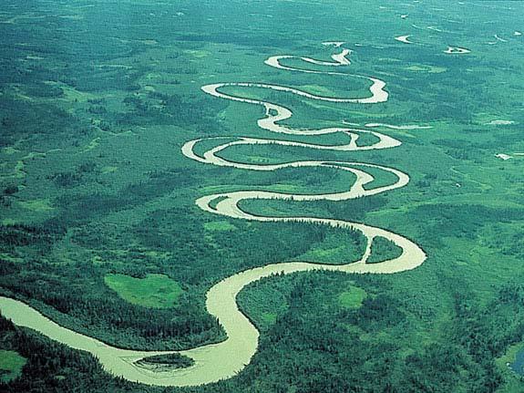
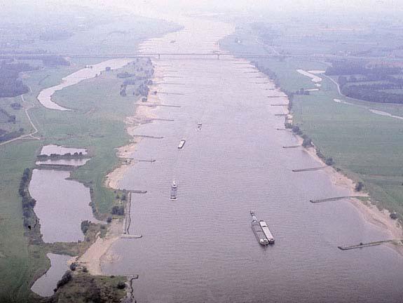
12 Avulsion and Chute Cutoffs Abrupt change in channel alignment resulting in a new channel within the floodplain Typically caused by: Concentrated overland flow Headcutting and/or scouring within floodplain Manmade disturbances Chute cutoff smaller scale than avulsion 12

13 Avulsion and Chute Cutoffs 13
14 Site Stability 14
15 Subsurface Entrainment Piping occurs when subsurface flow transports soil particles resulting in the development of a tunnel. Tunnels reduce soil cohesion causing slippage and ultimately streambank erosion. Typically caused by: Groundwater seepage Water level changes 15
16 Subsurface Entrainment 16
17 Groundwater table Normal water level Seepage flow Normal (baseflow( baseflow) ) conditions
18 Flood water level Seepage flow During flood peak
19 Area of high seepage gradients and uplift pressure Seepage flow Normal water level After flood recession
20 Site Stability 20
21 Scour Erosion at a specific location that is greater than erosion found at other nearby locations of the stream bed or bank. Simons and Sentruk (1992) 21
22 Scour Scour depths needed for: Revetment design Drop structures Highway structures Foundation design Anchoring systems Habitat enhancement 22
23 Scour Equations All empirical relationships Specific to scour type Designed for and with sand-bed systems May distinguish between live-bed and clear-water conditions Modifications for gravel-bed systems 23
24 Calculating Scour Identify type(s) of expected scour Calculate depth for each type Account for cumulative effect Compare to any know conditions 24
25 5 Types of Scour Bend scour Constriction scour Drop/weir scour Jet scour Local scour 25

26 Bend Scour 26
27 Bend Scour Caused by secondary currents Material removed from toe Field observations can be helpful in assessing magnitude Conservative first estimate: Equal to the flow depth upstream of bend Three empirical relationships 27
28 Bend Scour Three methods Thorne (1997) Flume and river experiments D 50 bed from 0.3 to 63 mm Applicable to gravel bed systems Maynord (1996) Used for sand-bed channels Provides conservative estimate for gravel-bed systems Wattanabe (Maynord 1996) Ditto 28
29 Thorne Equation d 1.07 log R c = 2 y W 1 Where d = maximum depth of scour (L) y 1 = average flow depth directly upstream of the bend (L) W = width of flow (L) R c = radius of curvature (L) R c 2< < 22 W 29
30 Maynord Equation D R W mb = c D W D u u Where D mb = maximum water depth in bend (L) D u = mean channel depth at upstream crossing (L) W = width of flow at upstream end of bend (L) R c = radius of curvature (L) R c W < < 1.5 < < W Du 30
31 Maynord Equation D R W mb = c D W D u u Notes: Developed from measured data on 215 sand bed channels Flow events between 1 and 5 year return intervals Not valid for overbank flows that exceed 20 percent of channel depth Equation is a best fit, not an envelope NO FOS Factor of safety of 1.08 is recommended English or metric units Width is that of active flow 31
32 Wattanabe Equation d s D W = α + β Rc Where d s = scour depth below maximum depth in bend (L) W = channel top width (L) R c = radius of curvature (L) D = mean channel depth (L) S = bed slope (L/L) f = Darcy friction factor α = X X X WS = log 10 D 2 β = π x f 1 x = f 1.42 sinσ + cosσ f σ tan = 1.5 f 1.42 f 32
33 Wattanabe Equation d s D α β W = + Rc Notes: Results correlated will with Mississippi River data Limits of application are unknown FOS of 1.2 is recommended English or metric units may be used 33
34 5 Types of Scour Bend scour Constriction scour Drop/weir scour Jet scour Local scour 34
35 Constriction Scour 35
36 Constriction Scour Occurs when channel features created a narrowing of the channel Typically, constriction is harder than the channel banks or bed Caused from natural and/or engineered features Large woody debris Bridge crossings Bedrock Flow training structures Tree roots/established vegetation 36
37 Constriction Scour Scour equations Developed from flume tests of bridge abutments Equations can be applied for natural or other induced constrictions Most accepted methods: Laursen live-bed equation (1980) Laursen clear-water equation (1980) 37
38 Constriction Scour Live-bed conditions Coarse sediments may armor the bed Compare with clear-water depth and use lower value Requires good judgment! Equation developed for sand-bed streams Application to gravel bed: Provides conservative estimate of scour depth 38
39 Laursen Live-Bed Equation y 2 Q 2 W 1 = y1 Q1 W2 d = y y A Where d = average depth of constriction scour (L) y 0 = average depth of flow in constricted reach without scour (L) y 1 = average depth of flow in upstream main channel (L) y 2 = average depth of flow in constricted reach after scour (L) Q 2 = flow in constricted section (L 3 /T) Q 1 = flow in upstream channel (L 3 /T) W 1 = bottom width in approach channel (L) W 2 = bottom width in constricted section (L) A = regression exponent 39
40 Laursen Live-Bed Equation y 2 Q 2 W 1 = y1 Q1 W2 d = y y A ω = fall velocity of D50 bed material (L/T) U* = shear velocity (L/T) = (gy 1 S e ) 0.5 g = acceleration due to gravity (L/T 2 ) S e = EGL slope in main channel (L/L) U*/ω < 0.5 A 0.59 Mode of bed Transport Bed 0.5 to Suspended > Suspended 40
41 Laursen Live-Bed Equation 41
42 Laursen Live-Bed Equation y 2 Q 2 W 1 = y1 Q1 W2 d = y y A Notes: Assumes all flow passes through constricted reach Coarse sediment may limit live-bed scour If bed is armored, compare with at clearwater scour Both English and metric units can be used 42
43 Laursen Clear-Water Equation Where 2 Q 2 y2 = CDm W2 d = y y d = average depth of constriction scour (L) y 0 = average depth of flow in constricted reach without scour (L) y 2 = average depth of flow in constricted reach after scour (L) Q 2 = flow in constricted section (L 3 /T) D m = 1.25D50 = assumed diameter of smallest non-transportable particle in bed material in constricted reach (L) W 2 = bottom width in constricted section (L) C = unit constant; 120 for English, 40 for metric 43
44 Laursen Clear-Water Equation Notes: y Q CD 0.67 W 2 m 2 = d = y y Only uses flow through constricted section If constriction has an overbank, separate computation made for the channel and each overbank Can be used for gravel bed systems Armoring analysis or movement by size fraction 44
45 5 Types of Scour Bend scour Constriction scour Drop/weir scour Jet scour Local scour 17 OCT address mistake on equation two slides ago 45
46 Drop/Weir Scour 46
47 Drop/Weir Scour Result of roller formed by cascading flow Caused from Perched culverts Culverts under pressure flow Spillway exits Natural drops in high-gradient mountain streams 47
48 Drop/Weir Scour Two methods U.S. Bureau of Reclamation Equation Vertical Drop Structure (1995) Used for scour estimation immediately downstream of a vertical drop Provides conservative estimate for sloping sills Laursen and Flick (1983) Sloping sills of rock or natural material 48
49 USBR Vertical Drop Equation = s t m d KH q d Where d s = scour depth immediately downstream of drop (m) q = unit discharge (m 3 /s/m) H t = total drop in head, measured from the upstream to downstream energy grade line (m) d m = tailwater depth immediately downstream of scour hole (m) K = regression constant of
50 USBR Vertical Drop Equation = s t m d KH q d Notes: Calculated scour depth is independent of bed-material grain size If large material is present, it may take decades for scour to reach final depth Must use metric units 50
51 Laursen and Flick Equation y R d = 4 3 y d c 50 s c m D50 yc Where d s = scour depth immediately downstream of drop (L) y c = critical flow depth (L) D 50 = median grain size of bed material (L) R 50 = median grain size of sloping sill (L) d m = tailwater depth immediately downstream of scour hole (L) 51
52 Laursen and Flick Equation y R d = 4 3 y d c 50 s c m D50 yc Notes Developed specifically for sloping sills constructed of rock Non-Conservative for other applications Can use English or metric units 52
53 5 Types of Scour Bend scour Constriction scour Drop/weir scour Jet scour Local scour 53

54 Jet Scour 54
55 Jet Scour Lateral bars Sub-channel formation 55
56 Jet Scour High energy side channel or tributary discharges 56
57 Jet Scour Tight radius of curvature 57
58 Jet Scour Very difficult problem to solve Simons and Senturk (1992) provide some guidance Good case for adding a substantial FOS 58
59 Jet Scour 59
60 Jet Scour 60
61 Jet Scour 61
62 5 Types of Scour Bend scour Constriction scour Drop/weir scour Jet scour Local scour 62

63 Local Scour 63
64 Local Scour Appears as tight scallops along a bank-line Depressions in a channel bed Generated by flow patterns around an object or obstruction Extent varies with obstruction Can be objective of design 64

65 Local Scour Pier Scour Equations 65
66 Local Scour Pier Scour Equations Developed for sand-bed rivers Provides conservative estimate for gravel-bed systems Can be applied to other obstructions Assumes object extends above water surface Colorado State University Equation 66
67 Local Scour Colorado State University Equation Can be applied to both live-bed and clear-water conditions Provides correction factor for bed material > 6 cm gravel beds Field verification shows equation to be conservative 67
68 CSU Pier Scour Equation d y y b = 2.0K KKK Fr 0.43 Where d = maximum depth of scour, measured below bed elevation (m) y 1 = flow depth directly upstream of pier (m) b = pier width (m) F r = approach Froude number K 1 K 4 = correction factors 68
69 CSU Pier Scour Equation d y y b = 2.0K KKK Fr K 1 = correction factor for pier nose shape
70 CSU Pier Scour Equation d y y b = 2.0K KKK Fr 0.43 K 1 = correction factor for pier nose shape For angle of attach > 5 o, K 1 = 1.0 For angle of attach 5 o Square nose K 1 = 1.1 Circular K 1 = 1.0 Group of cylinders K 1 = 1.0 Sharp nose K 1 =
71 CSU Pier Scour Equation d y y b = 2.0K KKK Fr 0.43 K 2 = correction factor for angle of attach of flow L K2 = Cosθ + Sinθ b Where L = length of pier (along flow line of angle of attach) (m) b = pier width (m) Θ = angle of attach (degrees)
72 CSU Pier Scour Equation d y y b = 2.0K KKK Fr 0.43 K 2 = correction factor for angle of attach of flow Θ L/b = 4 L/b = 8 L/b =
73 CSU Pier Scour Equation d y y1 K 3 = correction factor for bed conditions Selected for type and size of dunes Use 1.1 for gravel-bed rivers 0.65 b = 2.0K KKK Fr
74 CSU Pier Scour Equation d y y b = 2.0K KKK Fr K 3 = correction factor for bed conditions 0.43 Bed Condition clear water scour plane bed/anti-dune small dunes medium dunes large dunes Dune Height (m) n/a n/a 0.6 to 3 3 to 9 >9 K
75 CSU Pier Scour Equation d y y1 K 4 = correction factor for armoring of bed material K 4 varies between 0.7 and 1.0 K 4 = 1.0 for D 50 < 60 mm, or for V r > 1.0 K 4 = [1 0.89(1-V r ) 2 ] 0.5, for D 50 > 60 mm 0.65 b = 2.0K KKK Fr 0.43 V r = V ( ) V ( ) c90 V i V i V i D 0.65 b 50 = V c50 V = 6.19 y D c 1/6 1/3 1 c 75
76 V r = CSU Pier Scour Equation V ( ) V ( ) c90 V i V i d y y b = 2.0K KKK Fr V i D 0.65 b 50 = V c V = 6.19 y D c 1/6 1/3 1 c Where V = approach velocity (m/s) V r = velocity ratio V i = approach velocity when particles at pier begin to move (m/s) V c90 = critical velocity for D 90 bed material size (m/s) V c50 = critical velocity for D 50 bed material size (m/s) Y 1 = flow depth upstream of pier (m) D c = particle size selected to compute V c (m) 76
77 CSU Pier Scour Equation d y y b = 2.0K KKK Fr 0.43 Where d = maximum depth of scour, measured below bed elevation (m) y 1 = flow depth directly upstream of pier (m) b = pier width (m) F r = approach Froude number K 1 K 4 = correction factors 77
78 Local Scour Abutment scour 78
79 Local Scour Abutment scour Developed for sand-bed systems Provides conservative estimate for gravel-bed systems Can be applied to other obstructions Results can be reduced based on experience Froelich Equation 79
80 Local Scour Froehlich Equation Predicts scour as a function of shape, angle with respect to flow, length normal to flow and approach flow conditions Provides conservative estimate for gravel-bed systems Can be applied to other obstructions Assumes object extends above water surface 80
81 Froehlich Equation for Live- Bed Scour at Abutments d y 0.43 L' KK 1 2 Fr 1.0 = + y Where d = maximum depth of scour, measured below bed elevation (m) y = flow depth at abutment (m) F r = approach Froude number L = length of abutment projected normal to flow (m) K 1 K 2 = correction factors 81
82 Froehlich Equation for Live- Bed Scour at Abutments d y 0.43 L' = KK F r y L = length of abutment projected normal to flow (m) θ 82
83 Froehlich Equation d y 0.43 L' KK 1 2 Fr 1.0 = + y K 1 = correction factor for abutment shape K 1 = 1.0 for vertical abutment K 1 = 0.82 for vertical abutment with wing walls K 1 = 0.55 for spill through abutments 83
84 Froehlich Equation d y 0.43 L' KK 1 2 Fr 1.0 = + y K 2 = correction factor for angle of embankment to flow θ 84
85 Froehlich Equation d y 0.43 L' KK 1 2 Fr 1.0 = + y K 2 = correction factor for angle of embankment to flow 0.13 Where = angle between channel bank and abutment is > 90 degrees of embankment points upstream is < 90 degrees if embankment points downstream K 2 θ = 90 85
86 Check Method U.S. Bureau of Reclamation 86
87 Check Method U.S. Bureau of Reclamation Provides method to compute scour at: Channel bends Piers Grade-control structures Vertical rock banks or walls May not be as conservative as previous approaches 87
88 Check Method U.S. Bureau of Reclamation Computes scour depth by applying an adjustment to the average of three regime equations Neil equation (1973) Modified Lacey Equation (1930) Blench equation (1969) 88
89 Neil Equation y n q = y d bf q bf m Where y n = scour depth below design flow level (L) y bf = average bank-full flow depth (L) q d = design flow discharge per unit width (L 2 /T) q bf = bankfull flow discharge per unit width (L 2 /T) m = exponent varying from 0.67 for sand and 0.85 for coarse gravel 89
90 Neil Equation y n q = y d bf q bf m Obtain field measurements of an incised reach Compute bank-full discharge and associated hydraulics Determine scour depth 90
91 Modified Lacey Equation y L Q = 0.47 f 3.3 Where y L = mean depth at design discharge (L) Q = design discharge (L 3 /T) f = Lacey s silt factor = 1.76 D D 50 = median size of bed material (must be in mm!) 91
92 Blench Equation y B = q F 0.67 d 0.33 bo Where y B = depth for zero bed sediment transport (L) q d = design discharge per unit width (L 2 /T) F bo = Blench s zero bed factor 92
93 Blench Equation y B = q F 0.67 d 0.33 bo F bo = Blench s zero bed factor 93
94 Check Method U.S. Bureau of Reclamation Computes scour depth by applying an adjustment to the average of three regime equations Neil equation (1973) Modified Lacey Equation (1930) Blench equation (1969) Adjust as follows 94
95 Check Method U.S. Bureau of Reclamation d d d = N N N = K y L L L = K y K y B b B Where d N, d L, d B = depth of scour from Neil, Lacey and Blench equations, respectively K N, K L, K B = adjustment coefficients for each equation 95
96 Check Method U.S. Bureau of Reclamation K N, K L, K B Condition Neil-K N Lacey-K L Blench-K B Bend Scour Straight reach (wandering thalweg) Moderate bend Severe bend Right-angle bend Vertical rock bank or wall Nose of Piers Small dam or grade control
97 Check Method U.S. Bureau of Reclamation d d d = N N N = K y L L L = K y K y B b B Average values and compare to results of previous methods Appropriate level of conservatism?? 97
98 REFERENCES 1. Lane, E.W Design of stable channels. Transactions of the American Society of Civil Engineers. 120: U.S. Department of Transportation, Federal Highway Administration Design of Roadside Channel with Flexable Linings. Hydraulic Engineering Circular No. 15. Publication No. FHWA-IP Richardson, E.V. and S.R. Davis. U.S. Department of Transportation, Federal Highway Administration, Evaluating Scour at Bridges, Hydraulic Engineering Circular No. 18. Publication No. FHWA-IP U.S. Department of Transportation, Federal Highway Administration Highways in the River Environment. 5. Thorne, C.R., R.D. Hey and M.D. Newson Applied Fluvial Geomorphology for River Engineering and Management. John Wiley and Sons, Inc. New York, N.Y. 98
99 REFERENCES 6. Maynord, S Toe Scour Estimation on Stabilized Bendways. Journal of Hydraulic Engineering, American Society of Civil Engineers, Vol. 122, No U.S. Department of Transportation, Federal Highway Administration. 1955a. Stream Stability at Highway Structures. Hydraulic Engineering Circular No Laursen, E.M. and Flick, M.W Final Report, Predicting Scour at Bridges: Questions Not Fully Answered Scour at Sill Structures, Report ATTI-83-6, Arizona Department of Transportation. 9. Simons, D.B and Senturk, F Sediemnt Transport Technology, Water Resources Publications, Littleton, CO. 10. Bureau of Reclamation, Sediment and River Hydraulics Section Computing Degradation and Local Scour, Technical Guideline for Bureau of Reclamation, Denver, CO. 99
A STUDY OF LOCAL SCOUR AT BRIDGE PIERS OF EL-MINIA
 A STUDY OF LOCAL SCOUR AT BRIDGE PIERS OF EL-MINIA Dr. Gamal A. Sallam 1 and Dr. Medhat Aziz 2 ABSTRACT Bridges are critical structures that require a substantial investment to construct and serve an important
Countermeasure Calculations and Design
 Countermeasure Calculations and Design Summarized from Bridge Scour and Stream Instability Countermeasures, Experience, Selection, and Design Guidance, Second Edition, Publication No. FHWA NHI 01-003,
Aquifer an underground zone or layer of sand, gravel, or porous rock that is saturated with water.
 Aggradation raising of the streambed by deposition that occurs when the energy of the water flowing through a stream reach is insufficient to transport sediment conveyed from upstream. Alluvium a general
Evaluation of Scour Depth around Bridge Piers with Various Geometrical Shapes
 Evaluation of Scour Depth around Bridge Piers with Various Geometrical Shapes Dr. P. D. Dahe * Department of Civil Engineering, SGGSIE&T, Vishnupuri, Nanded (Maharashtra) S. B. Kharode Department of Civil
Stream Geomorphology. Leslie A. Morrissey UVM July 25, 2012
 Stream Geomorphology Leslie A. Morrissey UVM July 25, 2012 What Functions do Healthy Streams Provide? Flood mitigation Water supply Water quality Sediment storage and transport Habitat Recreation Transportation
CONCEPTS Conservational Channel Evolution and Pollutant Transport System
 CONCEPTS Conservational Channel Evolution and Pollutant Transport System Eddy J. Langendoen Watershed Physical Processes Research Unit National Sedimentation Laboratory USDA Agricultural Research Service
APPENDIX B Hydraulic Considerations for Pipeline Crossings of Stream Channels
 APPENDIX B Hydraulic Considerations for Pipeline Crossings of Stream Channels B-1 B-2 APPENDIX B HYDRAULIC CONSIDERATIONS FOR PIPELINE CROSSINGS OF STREAM CHANNELS Pipeline crossings of perennial, intermittent,
Bank stabilization by redirective structures on the Santa Clara River, Ventura County, CA
 116 Alex Yescas Senior Water Resources Engineer Atkins North America Bank stabilization by redirective structures on the Santa Clara River, Ventura County, CA Abstract The Santa Clara River is one of the
Upper Mississippi River Basin Environmental Management Program Workshop
 Presentation to the Upper Mississippi River Basin Environmental Management Program Workshop by Michael Rodgers River Engineer US Army Corps of Engineers, St. Louis District August 17, 2007 Engineering
MODELING OF LOCAL SCOUR AROUND AL-KUFA BRIDGE PIERS Saleh I. Khassaf, Saja Sadeq Shakir
 ISSN 2320-9100 11 International Journal of Advance Research, IJOAR.org Volume 1, Issue 8,August 2013, Online: ISSN 2320-9100 MODELING OF LOCAL SCOUR AROUND AL-KUFA BRIDGE PIERS Saleh I. Khassaf, Saja Sadeq
Erosion Rate is a Function of Erodibility and Excess Shear Stress = k ( o - c ) From Relation between Shear Stress and Erosion We Calculate c and
 From Relation between Shear Stress and Erosion We Calculate c and") Equilibrium, Shear Stress, Stream Power and Trends of Vertical Adjustment Andrew Simon USDA-ARS, Oxford, MS asimon@msa-oxford.ars.usda.gov Non-Cohesive versus Cohesive Materials Non-cohesive: sands and
Equilibrium, Shear Stress, Stream Power and Trends of Vertical Adjustment Andrew Simon USDA-ARS, Oxford, MS asimon@msa-oxford.ars.usda.gov Non-Cohesive versus Cohesive Materials Non-cohesive: sands and
Sensitivity Analysis of the Effective Parameters with Respect to Cantilever Type Failure in Composite Riverbanks
 Sensitivity Analysis of the Effective Parameters with Respect to Cantilever Type Failure in Composite Riverbanks A. Samadi 1, E. Amiri-Tokaldany 2, and M. H. Davoudi 3 1 Ph.D. Candidate, Department of
Step 5: Channel Bed and Planform Changes
 Step 5: Channel Bed and Planform Changes When disturbed, streams go through a series of adjustments to regain equilibrium with the flow and sediment supply of their watersheds. These adjustments often
Appendix F Channel Grade Control Structures
 Stream Simulation Appendix F Channel Grade Control Structures This appendix briefly describes permanent grade control structures that are sometimes needed in the upstream and/or downstream reaches adjacent
GEOL 652. Poudre River Fieldtrip
 GEOL 652. Poudre River Fieldtrip One of the more difficult variables to measure and/or estimate when studying flow in natural channels is that of roughness. Roughness, usually approximated with Manning
Geomorphic Importance of Winter Peak Flows and Annual Snowmelt Hydrographs in a Sierra Nevada Boulder-Bedrock River
 Geomorphic Importance of Winter Peak Flows and Annual Snowmelt Hydrographs in a Sierra Nevada Boulder-Bedrock River Scott McBain and Bill Trush McBain & Trush, Inc. Clavey River and Cherry Creek vicinity
River Meandering and Braiding. Pierre Y. Julien. Department of Civil and Environmental Engineering Colorado State University Fort Collins, Colorado
 River Meandering and Braiding Pierre Y. Julien Department of Civil and Environmental Engineering Colorado State University Fort Collins, Colorado River Mechanics and Sediment Transport Lima Peru January
Ways To Identify Background Verses Accelerated Erosion
 Ways To Identify Background Verses Accelerated Erosion Establish Background Condition From Old Ground Photos, Aerial Photos, and Maps Compare Rate Over Time At the Same Location, or for Reaches Channel
!"#$%&&'()*+#$%(,-./0*)%(!
*+#$%(,-./0*)%(!") 8:30 Sign in Hoosic River Revival Coalition!"#$%&&'()*+#$%(,-./0*)%(! 12-#30+4/#"5-(60 9:00 Welcome and Introductions 9:15 Goals for Today s Program: A Description of the Planning Process 9:30 First Session:
8:30 Sign in Hoosic River Revival Coalition!"#$%&&'()*+#$%(,-./0*)%(! 12-#30+4/#"5-(60 9:00 Welcome and Introductions 9:15 Goals for Today s Program: A Description of the Planning Process 9:30 First Session:
Hydraulic Design of Energy Dissipators for Culverts and Channels HEC 14 September 1983 Metric Version
 Hydraulic Design of Energy Dissipators for Culverts and Channels HEC 14 September 1983 Metric Version Welcome to HEC 14 - Hydraulic Design of Energy Dissipators for Culverts and Channels Table of Contents
PART 2:! FLUVIAL HYDRAULICS" HYDROEUROPE
 PART 2:! FLUVIAL HYDRAULICS" HYDROEUROPE 2009 1 HYDROEUROPE 2009 2 About shear stress!! Extremely complex concept, can not be measured directly!! Computation is based on very primitive hypotheses that
Why Stabilizing the Stream As-Is is Not Enough
 Why Stabilizing the Stream As-Is is Not Enough Several examples of alternatives to the County s design approach have been suggested. A common theme of these proposals is a less comprehensive effort focusing
Why Geomorphology for Fish Passage
 Channel Morphology - Stream Crossing Interactions An Overview Michael Love Michael Love & Associates mlove@h2odesigns.com (707) 476-8938 Why Geomorphology for Fish Passage 1. Understand the Scale of the
Do you think sediment transport is a concern?
 STREAM RESTORATION FRAMEWORK AND SEDIMENT TRANSPORT BASICS Pete Klingeman 1 What is Your Restoration Project Like? k? Do you think sediment transport is a concern? East Fork Lewis River, WA Tidal creek,
Rapid Geomorphic Assessments: RGA s
 Establishing Current Reference Conditions Rates and concentrations of suspended-sediment transport vary over time and space due to factors such as precipitation characteristics and discharge, geology,
HYDROLOGY AND HYDRAULICS MUSKEG RIVER BRIDGE
 PUBLIC WORKS CANADA HYDROLOGY AND HYDRAULICS MUSKEG RIVER BRIDGE KILOMETRE 207.9, LIARD HIGKWAY December 1978 I I f I I I I # Bolter Parish Trimble Ltd. ONLIULTINO Public Works, Canada, 9925-109 Street,
SCOPE OF PRESENTATION STREAM DYNAMICS, CHANNEL RESTORATION PLANS, & SEDIMENT TRANSPORT ANALYSES IN RELATION TO RESTORATION PLANS
 DESIGN METHODS B: SEDIMENT TRANSPORT PROCESSES FOR STREAM RESTORATION DESIGN PETER KLINGEMAN OREGON STATE UNIVERSITY CIVIL ENGINEERING DEPT., CORVALLIS 2 ND ANNUAL NORTHWEST STREAM RESTORATION DESIGN SYMPOSIUM
Uniform Channel Flow Basic Concepts. Definition of Uniform Flow
 Uniform Channel Flow Basic Concepts Hydromechanics VVR090 Uniform occurs when: Definition of Uniform Flow 1. The depth, flow area, and velocity at every cross section is constant 2. The energy grade line,
Technical Memorandum. To: From: Copies: Date: 10/19/2017. Subject: Project No.: Greg Laird, Courtney Moore. Kevin Pilgrim and Travis Stroth
 Technical Memorandum To: From: Greg Laird, Courtney Moore Kevin Pilgrim and Travis Stroth 5777 Central Avenue Suite 228 Boulder, CO 80301 www.otak.com Copies: [Electronic submittal] Date: 10/19/2017 Subject:
Fish Passage at Road Crossings
 Fish Passage at Road Crossings 1 Crossing Design Workshop Outline 1:00 to 2:00 Intro, Design Overview, Channel Width 2:00 to 2:15 Break 2:15 to 3:15 No-Slope, Stream Simulation Design 3:15 to 3:30 Break
CHAPTER 2- BACKGROUND. INVESTIGATIONS OF COMPOSITE ROUGHNESS COEFFICIENT IN A RIVER WITH LOW FLOW
 2. Background 2.1 Introduction The estimation of resistant coefficient and hence discharge capacity in a channel or river is one of the fundamental problems facing river engineers. When applying Manning
ADDRESSING GEOMORPHIC AND HYDRAULIC CONTROLS IN OFF-CHANNEL HABITAT DESIGN
 ADDRESSING GEOMORPHIC AND HYDRAULIC CONTROLS IN OFF-CHANNEL HABITAT DESIGN Conor Shea - Hydrologist U.S. Fish and Wildlife Service Conservation Partnerships Program Arcata, CA Learning Objectives Examine
Degradation Concerns related to Bridge Structures in Alberta
 Degradation Concerns related to Bridge Structures in Alberta Introduction There has been recent discussion regarding the identification and assessment of stream degradation in terms of how it relates to
Rock Sizing for Batter Chutes
 Rock Sizing for Batter Chutes STORMWATER MANAGEMENT PRACTICES Photo 1 Rock-lined batter chute Photo 2 Rock-lined batter chute 1. Introduction In the stormwater industry a chute is a steep drainage channel,
Rock Sizing for Small Dam Spillways
 Rock Sizing for Small Dam Spillways STORMWATER MANAGEMENT PRACTICES Photo 1 Rock-lined spillway on a construction site sediment basin Photo 2 Rock-lined spillway on a small farm dam 1. Introduction A chute
MATHEMATICAL MODELING OF FLUVIAL SEDIMENT DELIVERY, NEKA RIVER, IRAN. S.E. Kermani H. Golmaee M.Z. Ahmadi
 JOURNAL OF ENVIRONMENTAL HYDROLOGY The Electronic Journal of the International Association for Environmental Hydrology On the World Wide Web at http://www.hydroweb.com VOLUME 16 2008 MATHEMATICAL MODELING
NATURAL RIVER. Karima Attia Nile Research Institute
 NATURAL RIVER CHARACTERISTICS Karima Attia Nile Research Institute NATURAL RIVER DEFINITION NATURAL RIVER DEFINITION Is natural stream of water that flows in channels with ih more or less defined banks.
Objectives This tutorial demonstrates how to perform sediment transport simulations in SRH-2D.
 SMS v. 12.2 SRH-2D Tutorial Objectives This tutorial demonstrates how to perform sediment transport simulations in SRH-2D. Prerequisites SMS Overview tutorial SRH-2D Requirements SRH-2D Model Map Module
GLG362/GLG598 Geomorphology K. Whipple October, 2009 I. Characteristics of Alluvial Channels
 I. Characteristics of Alluvial Channels Self-formed morphology set by entrainment, transport, and deposition They move unconsolidated sedimentary materials present in the valley fill flood plain/bank flow
Stable Channel Analysis and Design
 PDHonline Course H145 (4 PDH) Stable Channel Analysis and Design Instructor: Joseph V. Bellini, PE, PH, DWRE, CFM 2012 PDH Online PDH Center 5272 Meadow Estates Drive Fairfax, VA 22030-6658 Phone & Fax:
Closed duct flows are full of fluid, have no free surface within, and are driven by a pressure gradient along the duct axis.
 OPEN CHANNEL FLOW Open channel flow is a flow of liquid, basically water in a conduit with a free surface. The open channel flows are driven by gravity alone, and the pressure gradient at the atmospheric
Inflow Seepage Influence on Pier Scour
 54 TRANSPORTATION RSARCH RCORD 121 Inflow Seepage Influence on Pier Scour STVN R. ABT, JRRY R. RICHARDSON, AND RODNY J. WITTLRS A flume study was conducted to investigate the influence of inflow seepage
(3) Sediment Movement Classes of sediment transported
 Sediment Movement Classes of sediment transported") (3) Sediment Movement Classes of sediment transported Dissolved load Suspended (and wash load ) Important for scouring algae Bedload (5-10% total load Moves along bed during floods Source of crushing for
(3) Sediment Movement Classes of sediment transported Dissolved load Suspended (and wash load ) Important for scouring algae Bedload (5-10% total load Moves along bed during floods Source of crushing for
(3) Sediment Movement Classes of sediment transported
 Sediment Movement Classes of sediment transported") 9/17/15 (3) Sediment Movement Classes of sediment transported Dissolved load Suspended load Important for scouring algae Bedload (5-10% total load) Moves along bed during floods Source of crushing for
9/17/15 (3) Sediment Movement Classes of sediment transported Dissolved load Suspended load Important for scouring algae Bedload (5-10% total load) Moves along bed during floods Source of crushing for
NATURE OF RIVERS B-1. Channel Function... ALLUVIAL FEATURES. ... to successfully carry sediment and water from the watershed. ...dissipate energy.
 1 2 Function... Sevier River... to successfully carry sediment and water from the watershed....dissipate energy. 3 ALLUVIAL FEATURES 4 CHANNEL DIMENSION The purpose of a stream is to carry water and sediment
Chapter 3.8: Energy Dissipators. By Dr. Nuray Denli Tokyay
 Chapter 3.8: Energy Dissipators By Dr. Nuray Denli Tokyay 3.1 Introduction A stilling basin is a short length of paved channel placed at the foot of a spillway or any other source of supercritical flow
Sessom Creek Sand Bar Removal HCP Task 5.4.6
 Sessom Creek Sand Bar Removal HCP Task 5.4.6 Prepared by: Dr. Thomas Hardy Texas State University Dr. Nolan Raphelt Texas Water Development Board January 6, 2013 DRAFT 1 Introduction The confluence of
Project (Project No. US-CA-62-2) Maintenance Inspection and Reports (Subtask 14.1) Inspection Report No.2
 Maintenance Inspection and Reports (Subtask 14.1) Inspection Report No.2") MEMORANDUM TO: FROM: Jim Well, Ducks Unlimited Mike Harvey, PhD, PG SUBJECT: M&T/ Llano Seco Fish Screen Project (Project No. US-CA-62-2) Maintenance Inspection and Reports (Subtask 14.1) Inspection Report
MEMORANDUM TO: FROM: Jim Well, Ducks Unlimited Mike Harvey, PhD, PG SUBJECT: M&T/ Llano Seco Fish Screen Project (Project No. US-CA-62-2) Maintenance Inspection and Reports (Subtask 14.1) Inspection Report
Riparian Assessment. Steps in the right direction... Drainage Basin/Watershed: Start by Thinking Big. Riparian Assessment vs.
 Riparian Assessment vs. Monitoring Riparian Assessment What is a healthy stream? Determine stream/riparian health Determine change or trend, especially in response to mgmt Classification = designation
Addressing the Impact of Road-Stream Crossing Structures on the Movement of Aquatic Organisms
 Scott Jackson University of Massachusetts Amherst Addressing the Impact of Road-Stream Crossing Structures on the Movement of Aquatic Organisms Dams Sub-standard Culverts Excessive Velocities Inlet Drop
MEANDER MIGRATION MODEL ASSESSMENT FOR THE JANUARY 2005 STORM, WHITMAN PROPERTY, SAN ANTONIO CREEK, VENTURA COUNTY, CALIFORNIA
 MEANDER MIGRATION MODEL ASSESSMENT FOR THE JANUARY 2005 STORM, WHITMAN PROPERTY, SAN ANTONIO CREEK, VENTURA COUNTY, CALIFORNIA Prepared by Eric Larsen, Ph.D. Mark Rains, Ph.D. October 2006 INTRODUCTION
Rock Sizing for Waterway & Gully Chutes
 Rock Sizing for Waterway & Gully Chutes WATERWAY MANAGEMENT PRACTICES Photo 1 Rock-lined waterway chute Photo 2 Rock-lined gully chute 1. Introduction A waterway chute is a stabilised section of channel
Lectures Hydrology & Fluvial Geomorphology. Gauley River Images. Ancients' (= Biblical) Model of Water (Hydrologic) Cycle
 Model of Water (Hydrologic) Cycle") Lectures 11-13 13 Hydrology & Fluvial Geomorphology Gauley River Images http://www.youtube.com/watch?v=eulmuyegtz4&feature=related Ancients' (= Biblical) Model of Water (Hydrologic) Cycle Stream Water
Lectures 11-13 13 Hydrology & Fluvial Geomorphology Gauley River Images http://www.youtube.com/watch?v=eulmuyegtz4&feature=related Ancients' (= Biblical) Model of Water (Hydrologic) Cycle Stream Water
Open Channel Flow Part 2. Ch 10 Young, notes, handouts
 Open Channel Flow Part 2 Ch 10 Young, notes, handouts Uniform Channel Flow Many situations have a good approximation d(v,y,q)/dx=0 Uniform flow Look at extended Bernoulli equation Friction slope exactly
B-1. Attachment B-1. Evaluation of AdH Model Simplifications in Conowingo Reservoir Sediment Transport Modeling
 Attachment B-1 Evaluation of AdH Model Simplifications in Conowingo Reservoir Sediment Transport Modeling 1 October 2012 Lower Susquehanna River Watershed Assessment Evaluation of AdH Model Simplifications
LEVEE DESIGN FOR FLOOD PROTECTION ON ALLUVIAL FANS
 LEVEE DESIGN FOR FLOOD PROTECTION ON ALLUVIAL FANS BRUCE M. PHILLIPS 1 ABSTRACT The dynamic nature of alluvial fans in arid environments offers numerous floodplain management challenges primarily due to
Business. Meteorologic monitoring. Field trip? Reader. Other?
 Business Meteorologic monitoring Field trip? Reader Other? Classification Streams Characterization Discharge measurements Why classify stream channels? Why Classify Stream Channels? Provides a common language
River Restoration and Rehabilitation. Pierre Y. Julien
 River Restoration and Rehabilitation Pierre Y. Julien Department of Civil and Environmental Engineering Colorado State University Fort Collins, Colorado River Mechanics and Sediment Transport Lima Peru
Perspectives on river restoration science, geomorphic processes, and channel stability
 Perspectives on river restoration science, geomorphic processes, and channel stability Stream Restoration Forum: Science and Regulatory Connections Andrew C. Wilcox Department of Geosciences University
Tom Ballestero University of New Hampshire. 1 May 2013
 Tom Ballestero University of New Hampshire 1 May 2013 1 Hydrology 2 Basic Hydrology Low flows most common Flows that fill the stream to the banks and higher are much less common Filling the stream to the
Hydraulics of bendway weirs
 River Basin Management IV 389 Hydraulics of bendway weirs C. Thornton 1, S. Abt 1, D. Baird 2 & R. Padilla 3 1 Colorado State University, Fort Collins, CO, USA 2 U.S. Bureau of Reclamation, Denver, CO,
Streams. Stream Water Flow
 CHAPTER 14 OUTLINE Streams: Transport to the Oceans Does not contain complete lecture notes. To be used to help organize lecture notes and home/test studies. Streams Streams are the major geological agents
MEANDER MIGRATION MODEL ASSESSMENT FOR THE 50- AND 100-YEAR STORMS, WHITMAN PROPERTY, SAN ANTONIO CREEK, VENTURA COUNTY, CALIFORNIA
 MEANDER MIGRATION MODEL ASSESSMENT FOR THE 50- AND 100-YEAR STORMS, WHITMAN PROPERTY, SAN ANTONIO CREEK, VENTURA COUNTY, CALIFORNIA Prepared by Eric Larsen, Ph.D. Mark Rains, Ph.D. October 2006 TABLE OF
Fluvial Processes in River Engineering
 Fluvial Processes in River Engineering Howard H. Chang San Diego State University... A WILEY-INTERSCIENCE PUBLTCATION John Wiley & Sons New York Chicbester Brisbane Toronto Singapore CONTENTS PARTI FLUVIAL
Calculation of Stream Discharge Required to Move Bed Material
 Calculation of Stream Discharge Required to Move Bed Material Objective: Students will map two sections of a stream and calculate the depth, velocity, and discharge of flows required to move the stream
Discharge. Discharge (Streamflow) is: Q = Velocity (L T -1 ) x Area (L 2 ) Units: L 3 T -1 e.g., m 3 s -1. Velocity. Area
 is: Q = Velocity (L T -1 ) x Area (L 2 ) Units: L 3 T -1 e.g., m 3 s -1. Velocity. Area") Discharge Discharge (Streamflow) is: Q = Velocity (L T -1 ) x Area (L 2 ) Units: L 3 T -1 e.g., m 3 s -1 Velocity Area Where is the average velocity?? 3 Source: Brooks et al., Hydrology and the Management
Discharge Discharge (Streamflow) is: Q = Velocity (L T -1 ) x Area (L 2 ) Units: L 3 T -1 e.g., m 3 s -1 Velocity Area Where is the average velocity?? 3 Source: Brooks et al., Hydrology and the Management
Stream Restoration and Environmental River Mechanics. Objectives. Pierre Y. Julien. 1. Peligre Dam in Haiti (deforestation)
") Stream Restoration and Environmental River Mechanics Pierre Y. Julien Malaysia 2004 Objectives Brief overview of environmental river mechanics and stream restoration: 1. Typical problems in environmental
Stream Restoration and Environmental River Mechanics Pierre Y. Julien Malaysia 2004 Objectives Brief overview of environmental river mechanics and stream restoration: 1. Typical problems in environmental
Erosion Surface Water. moving, transporting, and depositing sediment.
 + Erosion Surface Water moving, transporting, and depositing sediment. + Surface Water 2 Water from rainfall can hit Earth s surface and do a number of things: Slowly soak into the ground: Infiltration
Historical channel change on the Upper Gila River, Arizona and New Mexico in response to anthropogenic modifications and extreme floods
 Historical channel change on the Upper Gila River, Arizona and New Mexico in response to anthropogenic modifications and extreme floods www.archives.gov www.paztcn.wr.usgs.gov wrh.noaa.gov Upper Gila River
Dam Removal Analysis Guidelines for Sediment
 A review of: Dam Removal Analysis Guidelines for Sediment Joe Rathbun (Retired) rathbunj@sbcglobal.net Some Potential Sediment Issues Reservoir restoration Downstream water quality Downstream deposition
Avoiding Geohazards in the Mid-Atlantic Highlands by Using Natural Stream Principles
 Avoiding Geohazards in the Mid-Atlantic Highlands by Using Natural Stream Principles J. Steven Kite, WVU Neal Carte, WVDOT Will Harman, Michael Baker Corp. Donald D. Gray, WVU Photo: W. Gillespie North
Rock Sizing for Multi-Pipe & Culvert Outlets
 Rock Sizing for Multi-Pipe & Culvert Outlets STORMWATER AND WATERWAY MANAGEMENT PRACTICES Photo 1 Rock pad outlet structure at end of a duel stormwater pipe outlet Photo 2 Rock pad outlet structure at
Stream Entrainment, Erosion, Transportation & Deposition
 Lecture 12 Zone 2 of the Fluvial System, Continued Stream Entrainment, Erosion, Transportation & Deposition Erosion in a Fluvial Landscape Corrosion Chemical Erosion Corrasion Mechanical Weathering Cavitation
Dedicated to Major Contributors to the Concepts of Flow of Water and Sediment in Alluvial Channels:
 Geomorphic, Hydrologic, Hydraulic and Sediment Concepts Applied To Alluvial Rivers By Daryl B. Simons, Ph.D., P.E., D.B. Simons & Associates, Inc.; Everett V. Richardson, Ph.D., P.E., Ayres Associates,
The Importance of Riparian Vegetation in Channel Restoration: Moving Towards Quantification in Design
 The Importance of Riparian Vegetation in Channel Restoration: Moving Towards Quantification in Design Rob Millar Department of Civil Engineering The University of British Columbia "Nothing is as practical
[1] Performance of the sediment trap depends on the type of outlet structure and the settling pond surface area.
![[1] Performance of the sediment trap depends on the type of outlet structure and the settling pond surface area.](/thumbs/76/74245181.jpg "[1] Performance of the sediment trap depends on the type of outlet structure and the settling pond surface area.") Sediment Trench SEDIMENT CONTROL TECHNIQUE Type 1 System Sheet Flow Sandy Soils Type 2 System [1] Concentrated Flow Clayey Soils Type 3 System [1] Supplementary Trap Dispersive Soils [1] Performance of
Sediment Trench SEDIMENT CONTROL TECHNIQUE Type 1 System Sheet Flow Sandy Soils Type 2 System [1] Concentrated Flow Clayey Soils Type 3 System [1] Supplementary Trap Dispersive Soils [1] Performance of
The River Restoration Centre therrc.co.uk. Understanding Fluvial Processes: supporting River Restoration. Dr Jenny Mant
 The River Restoration Centre therrc.co.uk Understanding Fluvial Processes: supporting River Restoration Dr Jenny Mant Jenny@therrc.co.uk Understanding your catchment Hydrology Energy associated with the
How to Design Bendway Weirs
 How to Design Bendway Weirs Project Background U.S. Bureau of Reclamation: Middle Rio Grande Channel Maintenance Program 29-Mile Study Reach: Cochiti Dam to Bernalillo Geomorphic Changes Due to Dam Construction
PREDICTING UNDERSEEPAGE OF MASONRY DAMS Published in Proceedings of 29 th ASDSO Conference, Hollywood, FL, Sept Oct. 1, 2009.
 PREDICTING UNDERSEEPAGE OF MASONRY DAMS Published in Proceedings of 29 th ASDSO Conference, Hollywood, FL, Sept. 27 - Oct. 1, 29. Joshua M. Hendrix, EIT, US Army Corps of Engineers, Rock Island, IL Timothy
HAW CREEK, PIKE COUNTY, MISSOURI-TRIB TO SALT RIVER ERODING STREAM THREATHENING COUNTY ROAD #107, FOURTEEN FT TALL ERODING BANK WITHIN 4 FT OF THE
 HAW CREEK, PIKE COUNTY, MISSOURI-TRIB TO SALT RIVER ERODING STREAM THREATHENING COUNTY ROAD #107, FOURTEEN FT TALL ERODING BANK WITHIN 4 FT OF THE ROAD, PROJECT CONSTRUCTED IN 1 DAY, MARCH 10, 2009 BY
Stream Classification
 Stream Classification Why Classify Streams? Communication Tool Describe Existing Conditions & Trends Describe Restoration Goals Research Tool Morphologic Stream Classification Systems Schumm (1977) Alluvial
Module 2 Lecture 9 Permeability and Seepage -5 Topics
 Module 2 Lecture 9 Permeability and Seepage -5 Topics 1.2.7 Numerical Analysis of Seepage 1.2.8 Seepage Force per Unit Volume of Soil Mass 1.2.9 Safety of Hydraulic Structures against Piping 1.2.10 Calculation
SELBY CREEK STREAM HABITAT RESTORATION AND RIPARIAN REVEGETATION PROJECT: GEOMORPHIC ANALYSIS AND REVIEW
 SELBY CREEK STREAM HABITAT RESTORATION AND RIPARIAN REVEGETATION PROJECT: GEOMORPHIC ANALYSIS AND REVIEW Submitted to Bioengineering Institute P.O. Box 1554 Laytonville, CA 95454 By Matthew O Connor, PhD,
Surface Water and Stream Development
 Surface Water and Stream Development Surface Water The moment a raindrop falls to earth it begins its return to the sea. Once water reaches Earth s surface it may evaporate back into the atmosphere, soak
Channel Pattern. Channel Pattern, Meanders, and Confluences. Description of Channel Pattern. Bridge (2003)
") Channel Pattern Channel Pattern, Meanders, and Confluences Outline Description of channel pattern Alternate bars Channel pattern continua and evolution Controls of channel pattern Description of Channel
Channel Pattern Channel Pattern, Meanders, and Confluences Outline Description of channel pattern Alternate bars Channel pattern continua and evolution Controls of channel pattern Description of Channel
Water quality needs: Flow, velocity. Fish biologists need: Critical depth or velocity. Hydrology gives flows m 3 /s or day
 Environmental Water Allocation Hydraulics Dr L Beevers Heriot Watt University, it UK l.beevers@hw.ac.uk Overview Why hydraulics in EWA? Different types of flows Theory Case studies Review Why do we need
Appendix E Rosgen Classification
 Appendix E Stream Type s Using the morphometric parameters described above, stream reaches are classified into 7 major stream types (Aa+ through G) based on s (1996) criteria. The relevant stream classifications
Carmel River Bank Stabilization at Rancho San Carlos Road Project Description and Work Plan March 2018
 Carmel River Bank Stabilization at Rancho San Carlos Road Project Description and Work Plan March 2018 EXISTING CONDITION The proposed Carmel River Bank Stabilization at Rancho San Carlos Road Project
United States Army Corps of Engineers Engineering Manual EM
 United States Army Corps of Engineers Engineering Manual EM 1110-2-1601 1 Chapter 2 Open Channel Hydraulic Theory 2 Open Channel Hydraulic Theory Physical Hydraulic Elements Hydraulic Design Aspects Flow
 1.3.1.1 Incipient Motion Particle movement will occur when the instantaneous fluid force on a particle is just larger than the instantaneous resisting force related to the submerged particle weight and
Summary of Hydraulic and Sediment-transport. Analysis of Residual Sediment: Alternatives for the San Clemente Dam Removal/Retrofit Project,
 Appendix N SUMMARY OF HYDRAULIC AND SEDIMENT-TRANSPORT ANALYSIS OF RESIDUAL SEDIMENT: ALTERNATIVES FOR THE SAN CLEMENTE DAM REMOVAL/RETROFIT PROJECT, CALIFORNIA the San Clemente Dam Removal/Retrofit Project,
Lateral Inflow into High-Velocity Channels
 Lateral Inflow into High-Velocity Channels by Richard L. Stockstill PURPOSE: This Coastal and Hydraulics Engineering Technical Note (CHETN) investigates lateral flow discharging into a high-velocity channel.
Landscape Development
 Landscape Development Slopes Dominate Natural Landscapes Created by the interplay of tectonic and igneous activity and gradation Deformation and uplift Volcanic activity Agents of gradation Mass wasting
Sedimentation Scour Model Gengsheng Wei, James Brethour, Markus Grünzner and Jeff Burnham August 2014; Revised October 2014
 Flow Science Report 03-14 Sedimentation Scour Model Gengsheng Wei, James Brethour, Markus Grünzner and Jeff Burnham August 2014; Revised October 2014 1. Introduction The three-dimensional sediment scour
presented by Umut Türker Open Channel Flow
 presented by Umut Türker Open Channel Flow What is open channel flow? Open channel flow is a flow which has a free surface and flows due to the gravitational effect What is open channel flow? Open channel
Long Valley Meadow Restoration Project
 Long Valley Meadow Restoration Project USDA Forest Service Mogollon Rim Ranger District Coconino National Forest Coconino County, Arizona T13N, R9E, Section 12 and T13N, R10E, Sections 6 and 7 Gila and
Design and Construction
 Design and Construction Stream Simulation With power point slides shamelessly stolen from: Forest Service AOP Training Course Bob Gubernick Paul Anderson John Kattell USDA Forest Service Interim Directive
Fluvial Geomorphology
 Geomorphic Components of Riparian Ecosystems W. Barry Southerland, Ph.D. Fluvial Geomorphologist, CPESC #514 West National Technology Support Center Water Quality and Quantity Technology Development Team
APPENDIX A REACH DECRIPTIONS. Quantico Creek Watershed Assessment April 2011
 APPENDIX A REACH DECRIPTIONS Basin 615, South Fork of Quantico Creek - Project Reach Descriptions Reach Name: 615-A Coordinates (NAD 83, Virginia State Plane North): 11796510.57, 6893938.95 to 11801555.79,
Overview of fluvial and geotechnical processes for TMDL assessment
 Overview of fluvial and geotechnical processes for TMDL assessment Christian F Lenhart, Assistant Prof, MSU Research Assoc., U of M Biosystems Engineering Fluvial processes in a glaciated landscape Martin