After lecture 13 you should be able to
|
|
|
- Louisa Howard
- 6 years ago
- Views:
Transcription

1 Lecture 13: Design of paper and board packages Stacking, shocks, climate loading, analytical methods, computer based design tools After lecture 13 you should be able to use the most important analytical expressions for box compression strength describe analytical approaches for determination of the bending stiffness of paperboard and corrugated board panels qualitatively discuss the influence of non-perfect stacking perform simple design of cushioning materials describe how heat transfer mechanisms influences product protection 1
2 Literature Pulp and Paper Chemistry and Technology - Volume 4, Paper Products Physics and Technology, Chapter 10 Paperboard Reference Manual, pp Fundamentals of packaging technology, Chapter 15 Handbook of Physical Testing of Paper, Chapter 11 The design procedure Theoretical predictions Laboratory testing Full-scale testing Design Implement Test!! Not different from for example the automotive or many other types of industries! 2


 From")


3 Loads during transport and storage Transport between manufacturer, wholesaler and retailer by different types of vehicles Reloading by i.e. forklifts Many time consuming manual operations at wholesalers and retailers Varying climate conditions (temperature and moisture) From Jamialahmadi, Trost, Östlund, 2009 EXAMPLE: Stacking of boxes Static compression load Top-load compression of the most stressed package in the pallet. Most stressed package 3

 Determination of the maximum load that a rectangular box can")
4 Methods for determination of box compression strength Laboratory and service testing + Closest to reality and reliable - Time consuming and expensive to do parametric investigations Empirical analytical calculations + Quick to use with acceptable accuracy in many applications - Models approximate and less useful for parametric studies Numerical simulations of box deformation based on the finite element method (FEM) (Will be discussed in more detail in next lecture) + In general high accuracy and easy to do parametric investigations - Not straight-forward to use and still not fully developed for every paper and board application Box Compression Test (BCT) Determination of the maximum load that a rectangular box can carry. 4
5 Paperboard cartons Box compression strength of rectangular boxes Consider a box subjected to compressive loading due to stacking. 1. At small loadings, the load is evenly distributed along the perimeter of the box 2. At a certain load the panels of the box buckle in a characteristic way 3. At the corners of the box the corners themselves prevent buckling of the panels 4. Load is then primarily carried by small zones at the corners of the box 5. Failure of the box finally occurs by compressive failure at the corners Grangård (1969, 1970) show that the compression strength of PAPERBOARD boxes (the BCT-value) correlate well with the strength of laboratory tested panels. 5
6 Buckling of paperboard boxes Observation: In-plane stiffness of panel is in general much larger than bending stiffness Panel 1: This panel wants to buckle, i.e. the panel would like to deform in the x 1 -direction. 2 1 Panel 2: The in-plane deformation of this panel is small, i.e. this panel will not deform very much in the x 1 -direction. x 3 Consequently, close to the corners Panel 1 x 2 cannot deform in the x 1 -direction, and the corners will remain primarily vertical. x 1 Buckling of simply supported isotropic plate subjected to uniform compressive loading Timoshenko (1936) P c πt = 2 σ E sc 2 3(1 υ ) P c t = ultimate strength of buckled panel = plate thickness υ = Poisson's ratio E = in-plane Young's modulus σ = yield stress in compression sc 6
 per unit width S = S S b b b MD CD b Et S = 12 3 SCT F σ sc c t THEN FOR A PANEL: P")
7 Modifications for an anisotropic plates Introduce the geometric mean of the bending stiffness Introduce the bending stiffness per unit width, S b, instead of Young s modulus E and the panel thickness t Consider influence of Poisson s ratio to be negligible Replace σ sc by the short span compression strength (SCT) per unit width S = S S b b b MD CD b Et S = 12 3 SCT F σ sc c t THEN FOR A PANEL: P π F S S c = 2 SCT b b c MD CD Short Span Compression Strength SCT F c 07mm 0.7 7
8 BOX compression strength Paperboard boxes Grangård s formula: SCT P = k Fc Sb The constant k that is introduced instead of 2π may vary depending on the dimensions of the box and the design (type of box). This constant needs to be determined through extensive testing. The quality of the crease will also strong affect k. A comment on fibre orientation and mechanical properties Board dried with 2 % stretch in MD and free drying in CD 8
9 Corrugated board containers Stacking strength of corrugated board boxes (15 RSC boxes) Mean box compression strength, 5764 N Maximum, 6420 N Minimum, 5100 N Standard deviation, 374 N Coefficient of variation, 6.5 % 9
10 Analysis of typical load-deformation curve Load versus deformation for an A- flute RSC-box using fixed platens. A. Any unevenness in the box is levelled ll out. Top crease lines begin to roll. B. The steepest corners of the box start to take load. C. Sub-peak caused by smallscale yielding of one of the fold crease lines. D. Buckling of long panels. E. Maximum load. Collapse of box corners and buckling of short panels. F. Localized stability Usefulness of box compression strength Boxes are tested individually. If boxes are stacked in patterns other than a columns the full strength potential will not be realized. Climatic conditions may degrade box compression strength. Creep will affect the results considerably. The box may be subjected to dynamic loading, such as vibrations, that will accelerate failure. 10
 1 b b 1 b P Z = c Fc")
11 BOX compression strength McKee s formula P = β F S Z c 0,75 0,25 0,5 c P c = Box compression strength F c = Compressive strength of plane panel (ECT) S = Geometric mean of MD and CD bending stiffness Z = Perimeter of box β = Empirical constant S b MD S b CD The McKee model Semi-empirical approach for description of the post-buckling behaviour P P F Z CR c cb, = constants ( ) 1 b b 1 b P Z = c Fc PCR = ultimate strength of the panel = buckling load for simply supported plate = edgewise compression strength of panel (ECT) 11

12 The McKee model Buckling load for thin orthotropic panel where k P CR CR = S S W MD CD 12kCR π r n = n r r S MD = SCD /4 t W K W t n is related to the buckling pattern The McKee model Approximations 1. The parameter K is a complex function of several corrugated board and liner parameters, but the value K = 0,5 was adopted by McKee without further notice. 2. The parameter ( S ) 1/4 MD SCD was set to 1,17 from practical measurements. 3. The panel width was related to the perimeter Z by W = Z/4, i.e. a square box. 12
13 Simplified expression for total box load b 2 2b b b b 2b 1 1 b = ( 4π ) ( 1 c) ( MD CD ) P c F S S Z k where k is a modified buckling coefficient. 1 b = 1,33 when b 0, 76 Further simplifications: for boxes with depth-to-perimeter values 0,143 k ( ) b b b b 2 b 1 c MD CD P = af S S Z Evaluation of constants a and b for A-, B- and C-flute RSCboxes yields in SI-units: b b P= 375F S S Z ( ) 0,25 0,75 0,5 c MD CD Comments on McKee s formula The constants evaluated for typical U.S. boxes in the early 1960s It assumes that the boxes are square, but modification for the effect of aspect ratio exists. It predicts maximum load, but not deformation. Influence of transverse shear is ignored. Examining boxes during failure often reveals a pattern that suggests the presence of shear near the corners (leaning flutes). 13

14 Influence of box perimeter and height on BCT-value Box compression strength/n Height/mm Perimeter/mm Failure in corrugated board panels 1. Global buckling 2. Failure initiated by local buckling in the corner regions of the concave side of a panel 3. Multi-axial stress state! Nordstrand (2004) 14

15 Micromechanical models Tensile stiffness: Bending stiffness: EA = EBt E = Et per unit width b 3 Bt S = EI = E 12 3 b t S = E per unit width 12 Micromechanical models of corrugated board t t liner t t liner 15
16 In-plane stiffness of corrugated board panels core E 0 α take-up factor E MD t α core fluting CD = tcore E fluting CD t fluting fluting thickness t core core thickness liner, bottom tliner, bottom liner, top tliner, top EMD = EMD + EMD t t liner, bottom tliner, bottom core tcore t liner, top liner, top ECD = ECD + ECD + ECD t t t Rules of mixture from parallel model for lamellar composites Simplified expressions for the bending stiffness of corrugated board panels A first order approximation in both MD and CD neglects the influence of the medium. However, the medium should give an appreciable contribution to the bending stiffness, particularly in CD liner t t t I = Btliner + Btliner = Btliner Steiner s theorem! liner b liner t t t S = E tliner = Eb = { Steadman} = S More advanced models exist, but they are cumbersome to use, and cannot be considered to be part of a fundamental course on packaging materials. Needs to be implemented into easy-to-use software. Numerical calculation of the bending stiffness is of course also possible and explored in the scientific literature. 16


17 Stacking - Alternative load cases Roll cage The corrugated board boxes are 1 not stacked perfectly on top of each other stacked incorrectly leaning 6 7 stacked on other products than boxes Ranking of load cases Average number of loaded vertical box panels
18 Safe and risky load cases In average 4-2,5 loaded vertical panels 4 3,5 3 2,5 Critical load cases In average 2-0 loaded vertical panels ,
19 Distribution of load cases for a sample containing 290 boxes 25% 100% 20% 80% 15% 60% Frekvens Ack. frekvens 10% 40% 5% 20% 0% 0 0,5 1 1,5 2 2,5 3 3,5 4 el. obel. 194 rent belastade lådor antal belastade sidopaneler (ABS-tot) 100% = 290 lådor 0% BCT-value of paperboard boxes BCT N 250 Stacking strength Staplingsstyrka for two boxes två kapslar on top i höjd of each other (correct (rätt, förskjuten stacking and 6 mm displaced längs, förskjuten 6 mm in different 6 mm längs directions) och åt sidan) 200 medelvärde average standardavvikelse. dev stacking förskjutningsmönster pattern 19
20 Product package interaction Interaction between packages P P δ Primary packaging δ Secondary packaging Interaction between packages Influence of head space P P δ δ 20
 EUPS (European standard for defining the")
21 Company relates software for analysis of box compression strength In general, paper companies have in-house developed software for box compression analysis. Optipack from Korsnäs Performance-Service/OptiPack/# Billerud Box Design CD SCA (based on analyses using the finite element method) EUPS (European standard for defining the strength characteristics of corrugated packaging. The End Use Performance Standard, EUPS, is based on studies of supply chain requirements. It provides comprehensive performance criteria that can be applied when selecting corrugated board.) Optipack 21


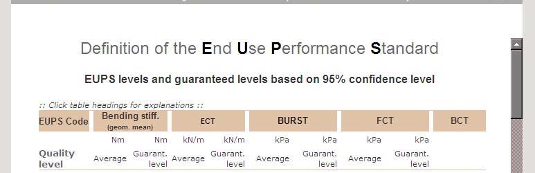
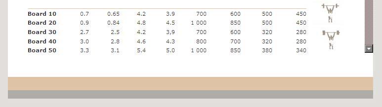
22 Billerud Box Design EUPS 22
23 EUPS Bending Stiffness Calculations Bending Stiffness Calculation Single wall board : Corrugated Board: Liner Specific: Fluting Specific: Wall: Inner liner: Inside fluting: Tensile Stiffness, Tensile Stiffness, Flute Height: 3,66 mm CD 425 kn/m CD 345 kn/m Flute Pitch: 7,95 mm Tensile Stiffness, MD 1150 kn/m Thickness 184 μm Take-up factor: 1,42 (cal.) Thickness 165 μm Outer liner: Tensile Stiffness, CD Tensile Stiffness, MD Thickness 425 kn/m 1150 kn/m 165 μm Predicted Geometrical Mean of Bending Stiffness: 5,4 (Nm) (Disregarded w hen Double flute boards are calculated) Double wall board : Wall: Middle Liner: Outside Fluting: Tensile Stiffness, Tensile Stiffness, Flute Height: 2,5 mm CD 425 kn/m CD 345 kn/m Flute Pitch: 6,5 mm Tensile Stiffness, MD 1150 kn/m Thickness 184 μm Take-up factor: 1,31 (cal.) Thickness 165 μm Predicted Geometrical Mean of Bending Stiffness: 16,8 (Nm) (Disregarded w hen Single w all boards are calculated) Design against shocks 23
 Measure the acceleration (retardation) (expressed as a multiple of the acceleration due to")
24 Design of shock absorbance/damping materials A. No damping B. Incorrect damping C. Correct damping A B C Drop testing Drop the product against an elastic foundation (Winkler foundation) Measure the acceleration (retardation) (expressed as a multiple of the acceleration due to gravity, g) [alternatively measure the force during the drop test] By successively increasing the stiffness of the shock absorber/damping material, the value at which the product fails can be determined. 24
25 Drop testing - II In general, different values will be obtained depending on the orientation of the product. The durability against shocks is measured in multiples of g. For electronic devices, for example, this value is typically 20-80g. The packaging price is increasing very quickly if the durability value is below 20g. Drop and impact testing of packaging 25
26 Loads during transport and handling Shocks Drop a package Movement of package during vehicle transportation Overturn a package It is in practise impossible to estimate a design drop height that a package possibly can be subjected to during handling. Loads during transport and handling Design must be based on experience Low weight products are in general treated less carefully than heavy products. Package stacked on pallets are in general subjected to lower drop height than single packaging. Typically design values are 0,3 1,0 m. 26

 h = drop height")


27 Typical designs of cushioning c = The mechanical properties of damping materials at h a = retardation (in g) h = drop height T = thickness of damping material W W mgh = V W = impact energy (strain energy) per unit volume m = mass g = constant of gravity V = volume of damping material 27
28 Optimal damping factor The cushioning factor varies depending on how the mechanical behaviour of the material is utilised. The cushioning factor is dependent of the load rate (through h) There is an optimal impact energy for the cushioning material. For lower values is the material not used efficiently For higher values is the material thickness not high enough A good damping material has a value of the cushioning factor c not below 2-3 m/s 2 Corrugated board Typical dampening factor + Low price - Damaged after one shock - Small working region W min -W max - Hygroscopic 28
29 Foam Typical dampening factor + Can be tailor made to different shapes + Good damping properties + Can be obtained in different stiffness - Damaged during shock loading. Will lose some of its damping properties. Foam particles Typical dampening factor + Can be used as filler + Packing density can vary - Not as good damping properties as homogeneous materials 29
30 Example of cushioning factor Cushioning factor c = damping factor Design for box performance in a given environment Simulate given environmental conditions Test box performance using a realistic load Compare with, for example, design against metal fatigue in the vehicle industry 30
31 Design for heat isolation of packaging The physical problem is to prevent heat transport. 1. Isolate by use of an isolation material 2. Avoid that the product is exposed to heat (fans, cooling systems etc.) Principles for heat transport Conduction (sv. värmeledning) Through bodies Convection (sv. konvektion) At solids/fluid or fluids/fluids interfaces Radiation (sv. strålning) 31
 depends on temperature Convection (konvektion) at solids/fluid or")


32 Heat transport warm cold warm Conduction (värmeledning) through bodies depends on temperature gradient Radiation (strålning) depends on temperature Convection (konvektion) at solids/fluid or fluids/fluids interfaces depends on surface roughness and mixing Conduction Fourier s law Fourier's law is an empirical law. The rate of heat flow, dq/dt, through a homogenous solid is directly proportional to the area, A, of the section at right angles to the direction of heat flow, and to the temperature difference along the path of heat flow, dt/dx i.e. λ= heat conductivity coefficient 32

 k as: dq = ka ( T 2 T 1) dt k = 1 1 dm 1 + + α λ")
33 Convection Heat transfer from the solid surface to the fluid can be described by Newton's law of cooling. It states that the heat transfer, dq/dt, from a solid surface of area A, at a temperature Tw, to a fluid of temperature T, is: α = heat transfer coefficient Heat transfer coefficient Combining conduction and convection gives the total heat transfer coefficient (värmeövergångstal) k as: dq = ka ( T 2 T 1) dt k = 1 1 dm α λ α 1 m m 2 33
 dq = F A σ T T dt object-wall object object wall For concentric bodies with A object << A wall, the geometry factor F object-wall is ε")
34 Radiation σ = 0 ε 1 (emissivity, for a non-black body) Emitted energy-rate dq = εσ AT dt , W/m K (Stefan-Bolzmann constant) For object in an enclosure the radiative exchange between object and wall is 4 T is the absolute temperature in K 4 4 ( ) dq = F A σ T T dt object-wall object object wall For concentric bodies with A object << A wall, the geometry factor F object-wall is ε object. After lecture 13 you should be able to use the most important analytical expressions for box compression strength describe analytical approaches for determination of the bending stiffness of paperboard and corrugated board panels qualitatively discuss the influence of non-perfect stacking perform simple design of cushioning materials describe heat transfer mechanisms that influences product protection 34
Design of paper and board packages
 Lecture 14: Design of paper and board packages Design of paper and board packaging: stacking, analytical methods. Software such as Billerud Box Design, EUPS, Model PACK & Korsnäs After lecture 14 you should
Packaging Materials, SE2127 Problems with Solutions
 Packaging Materials, SE2127 Problems with Solutions Compiled by Mikael S. Magnusson and Sören Östlund Department of Solid Mechanics Royal Institute of Technology - KTH, Stockholm, Sweden 2010 Contents
Computational Analysis for Composites
 Computational Analysis for Composites Professor Johann Sienz and Dr. Tony Murmu Swansea University July, 011 The topics covered include: OUTLINE Overview of composites and their applications Micromechanics
After lecture 16 you should be able to
 Lecture 16: Design of paper and board packaging Advanced concepts: FEM, Fracture Mechanics After lecture 16 you should be able to describe the finite element method and its use for paper- based industry
FEA A Guide to Good Practice. What to expect when you re expecting FEA A guide to good practice
 FEA A Guide to Good Practice What to expect when you re expecting FEA A guide to good practice 1. Background Finite Element Analysis (FEA) has transformed design procedures for engineers. Allowing more
NORMAL STRESS. The simplest form of stress is normal stress/direct stress, which is the stress perpendicular to the surface on which it acts.
 NORMAL STRESS The simplest form of stress is normal stress/direct stress, which is the stress perpendicular to the surface on which it acts. σ = force/area = P/A where σ = the normal stress P = the centric
Mechanics of Materials Primer
 Mechanics of Materials rimer Notation: A = area (net = with holes, bearing = in contact, etc...) b = total width of material at a horizontal section d = diameter of a hole D = symbol for diameter E = modulus
Machine Direction Strength Theory of Corrugated Fiberboard
 Thomas J. Urbanik 1 Machine Direction Strength Theory of Corrugated Fiberboard REFERENCE: Urbanik.T.J., Machine Direction Strength Theory of Corrugated Fiberboard, Journal of Composites Technology & Research,
Unit 18 Other Issues In Buckling/Structural Instability
 Unit 18 Other Issues In Buckling/Structural Instability Readings: Rivello Timoshenko Jones 14.3, 14.5, 14.6, 14.7 (read these at least, others at your leisure ) Ch. 15, Ch. 16 Theory of Elastic Stability
KINK BAND FORMATION OF FIBER REINFORCED POLYMER (FRP)
") KINK BAND FORMATION OF FIBER REINFORCED POLYMER (FRP) 1 University of Science & Technology Beijing, China, niukm@ustb.edu.cn 2 Tsinghua University, Department of Engineering Mechanics, Beijing, China,
KINK BAND FORMATION OF FIBER REINFORCED POLYMER (FRP) 1 University of Science & Technology Beijing, China, niukm@ustb.edu.cn 2 Tsinghua University, Department of Engineering Mechanics, Beijing, China,
Finite Element Analysis of Corrugated Board under Bending Stress
 J. Fac. Agr., Kyushu Univ., 57 (1), 181 188 (2012) Finite Element Analysis of Corrugated Board under Bending Stress Jongmin PARK 1, Ghiseok KIM 2, Soonhong KWON 1, Sungwon CHUNG 1, Soongoo KWON 1, Wonsick
TABLE OF CONTENTS. Mechanics of Composite Materials, Second Edition Autar K Kaw University of South Florida, Tampa, USA
 Mechanics of Composite Materials, Second Edition Autar K Kaw University of South Florida, Tampa, USA TABLE OF CONTENTS 1. INTRODUCTION TO COMPOSITE MATERIALS 1.1 Introduction... 1.2 Classification... 1.2.1
Chapter 3. Load and Stress Analysis
 Chapter 3 Load and Stress Analysis 2 Shear Force and Bending Moments in Beams Internal shear force V & bending moment M must ensure equilibrium Fig. 3 2 Sign Conventions for Bending and Shear Fig. 3 3
*MAT_PAPER - a new orthotropic elastoplastic model for paper materials
 *MAT_PAPER - a new orthotropic elastoplastic model for paper materials Jesper Karlsson, Dynamore Nordic Mikael Schill, Dynamore Nordic Johan Tryding, Tetra Pak *MAT_PAPER (*MAT_274) A new orthotropic elastoplastic
1 INTRODUCTION 2 SAMPLE PREPARATIONS
 Chikage NORITAKE This study seeks to analyze the reliability of three-dimensional (3D) chip stacked packages under cyclic thermal loading. The critical areas of 3D chip stacked packages are defined using
PREDICTION OF BUCKLING AND POSTBUCKLING BEHAVIOUR OF COMPOSITE SHIP PANELS
 FONDATĂ 1976 THE ANNALS OF DUNAREA DE JOS UNIVERSITY OF GALATI. FASCICLE IX. METALLURGY AND MATERIALS SCIENCE N 0. 007, ISSN 15 08X PREDICTION OF BUCKLING AND POSTBUCKLING BEHAVIOUR OF COMPOSITE SHIP PANELS
University of Sheffield The development of finite elements for 3D structural analysis in fire
 The development of finite elements for 3D structural analysis in fire Chaoming Yu, I. W. Burgess, Z. Huang, R. J. Plank Department of Civil and Structural Engineering StiFF 05/09/2006 3D composite structures
BEAMS AND PLATES ANALYSIS
 BEAMS AND PLATES ANALYSIS Automotive body structure can be divided into two types: i. Frameworks constructed of beams ii. Panels Classical beam versus typical modern vehicle beam sections Assumptions:
PURE BENDING. If a simply supported beam carries two point loads of 10 kn as shown in the following figure, pure bending occurs at segment BC.
 BENDING STRESS The effect of a bending moment applied to a cross-section of a beam is to induce a state of stress across that section. These stresses are known as bending stresses and they act normally
Lecture 8 Viscoelasticity and Deformation
 Read: pg 130 168 (rest of Chpt. 4) 1 Poisson s Ratio, µ (pg. 115) Ratio of the strain in the direction perpendicular to the applied force to the strain in the direction of the applied force. For uniaxial
D : SOLID MECHANICS. Q. 1 Q. 9 carry one mark each. Q.1 Find the force (in kn) in the member BH of the truss shown.
 in the member BH of the truss shown.") D : SOLID MECHANICS Q. 1 Q. 9 carry one mark each. Q.1 Find the force (in kn) in the member BH of the truss shown. Q.2 Consider the forces of magnitude F acting on the sides of the regular hexagon having
D : SOLID MECHANICS Q. 1 Q. 9 carry one mark each. Q.1 Find the force (in kn) in the member BH of the truss shown. Q.2 Consider the forces of magnitude F acting on the sides of the regular hexagon having
Dynamic Response Of Laminated Composite Shells Subjected To Impulsive Loads
 IOSR Journal of Mechanical and Civil Engineering (IOSR-JMCE) e-issn: 2278-1684,p-ISSN: 2320-334X, Volume 14, Issue 3 Ver. I (May. - June. 2017), PP 108-123 www.iosrjournals.org Dynamic Response Of Laminated
*MAT_PAPER and *MAT_COHESIVE_PAPER: Two New Models for Paperboard Materials
 14 th International LS-DYNA Users Conference Session: Constitutive Modeling *MAT_PAPER and *MAT_COHESIVE_PAPER: Two New Models for Paperboard Materials Jesper Karlsson 1, Mikael Schill 1, Johan Tryding
ε t increases from the compressioncontrolled Figure 9.15: Adjusted interaction diagram
 CHAPTER NINE COLUMNS 4 b. The modified axial strength in compression is reduced to account for accidental eccentricity. The magnitude of axial force evaluated in step (a) is multiplied by 0.80 in case
PLATE GIRDERS II. Load. Web plate Welds A Longitudinal elevation. Fig. 1 A typical Plate Girder
 16 PLATE GIRDERS II 1.0 INTRODUCTION This chapter describes the current practice for the design of plate girders adopting meaningful simplifications of the equations derived in the chapter on Plate Girders
Lecture 7, Foams, 3.054
 Lecture 7, Foams, 3.054 Open-cell foams Stress-Strain curve: deformation and failure mechanisms Compression - 3 regimes - linear elastic - bending - stress plateau - cell collapse by buckling yielding
EE C245 ME C218 Introduction to MEMS Design
 EE C245 ME C218 Introduction to MEMS Design Fall 2007 Prof. Clark T.-C. Nguyen Dept. of Electrical Engineering & Computer Sciences University of California at Berkeley Berkeley, CA 94720 Lecture 16: Energy
CHAPTER 6 HEAT DISSIPATION AND TEMPERATURE DISTRIBUTION OF BRAKE LINER USING STEADY STATE ANALYSIS
 131 CHAPTER 6 HEAT DISSIPATION AND TEMPERATURE DISTRIBUTION OF BRAKE LINER USING STEADY STATE ANALYSIS 6.1 INTRODUCTION Drum brakes were the first types of brakes used on motor vehicles. Nowadays, over
Design of Beams (Unit - 8)
") Design of Beams (Unit - 8) Contents Introduction Beam types Lateral stability of beams Factors affecting lateral stability Behaviour of simple and built - up beams in bending (Without vertical stiffeners)
Design of Beams (Unit - 8) Contents Introduction Beam types Lateral stability of beams Factors affecting lateral stability Behaviour of simple and built - up beams in bending (Without vertical stiffeners)
THE EFFECT OF GEOMETRY ON FATIGUE LIFE FOR BELLOWS
 Advanced Materials Development and Performance (AMDP2011) International Journal of Modern Physics: Conference Series Vol. 6 (2012) 343-348 World Scientific Publishing Company DOI: 10.1142/S2010194512003418
Influence of residual stresses in the structural behavior of. tubular columns and arches. Nuno Rocha Cima Gomes
 October 2014 Influence of residual stresses in the structural behavior of Abstract tubular columns and arches Nuno Rocha Cima Gomes Instituto Superior Técnico, Universidade de Lisboa, Portugal Contact:
five Mechanics of Materials 1 ARCHITECTURAL STRUCTURES: FORM, BEHAVIOR, AND DESIGN DR. ANNE NICHOLS SUMMER 2017 lecture
 ARCHITECTURAL STRUCTURES: FORM, BEHAVIOR, AND DESIGN DR. ANNE NICHOLS SUMMER 2017 lecture five mechanics www.carttalk.com of materials Mechanics of Materials 1 Mechanics of Materials MECHANICS MATERIALS
Using the Timoshenko Beam Bond Model: Example Problem
 Using the Timoshenko Beam Bond Model: Example Problem Authors: Nick J. BROWN John P. MORRISSEY Jin Y. OOI School of Engineering, University of Edinburgh Jian-Fei CHEN School of Planning, Architecture and
Soft Bodies. Good approximation for hard ones. approximation breaks when objects break, or deform. Generalization: soft (deformable) bodies
 bodies") Soft-Body Physics Soft Bodies Realistic objects are not purely rigid. Good approximation for hard ones. approximation breaks when objects break, or deform. Generalization: soft (deformable) bodies Deformed
Soft-Body Physics Soft Bodies Realistic objects are not purely rigid. Good approximation for hard ones. approximation breaks when objects break, or deform. Generalization: soft (deformable) bodies Deformed
BUCKLING COEFFICIENTS FOR SIMPLY SUPPORTED, FLAT, RECTANGULAR SANDWICH PANELS UNDER BIAXIAL COMPRESSION
 U. S. FOREST SERVICE RESEARCH PAPER FPL 135 APRIL 1970 BUCKLING COEFFICIENTS FOR SIMPLY SUPPORTED, FLAT, RECTANGULAR SANDWICH PANELS UNDER BIAXIAL COMPRESSION FOREST PRODUCTS LABORATORY, FOREST SERVICE
Calculation of Damage-dependent Directional Failure Indices from the Tsai-Wu Static Failure Criterion
 Van Paepegem, W. and Degrieck, J. (3. alculation of Damage-dependent Directional Failure Indices from the sai-wu Static Failure riterion. omposites Science and echnology, 63(, 35-3. alculation of Damage-dependent
TRIALS WITH A SIMPLIFIED METHOD FOR BUCKLING AND ULTIMATE STRENGTH ANALYSIS OF COMPOSITE PLATES
 DEPT. OF MATH., UNIVERSITY OF OSLO RESEARCH REPORT IN MECHANICS, No. 1 ISSN 0801-9940 December 2012 TRIALS WITH A SIMPLIFIED METHOD FOR BUCKLING AND ULTIMATE STRENGTH ANALYSIS OF COMPOSITE PLATES by Qiao
EMA 3702 Mechanics & Materials Science (Mechanics of Materials) Chapter 2 Stress & Strain - Axial Loading
 Chapter 2 Stress & Strain - Axial Loading") MA 3702 Mechanics & Materials Science (Mechanics of Materials) Chapter 2 Stress & Strain - Axial Loading MA 3702 Mechanics & Materials Science Zhe Cheng (2018) 2 Stress & Strain - Axial Loading Statics
MA 3702 Mechanics & Materials Science (Mechanics of Materials) Chapter 2 Stress & Strain - Axial Loading MA 3702 Mechanics & Materials Science Zhe Cheng (2018) 2 Stress & Strain - Axial Loading Statics
D : SOLID MECHANICS. Q. 1 Q. 9 carry one mark each.
 GTE 2016 Q. 1 Q. 9 carry one mark each. D : SOLID MECHNICS Q.1 single degree of freedom vibrating system has mass of 5 kg, stiffness of 500 N/m and damping coefficient of 100 N-s/m. To make the system
Mechanics of Solids. Mechanics Of Solids. Suraj kr. Ray Department of Civil Engineering
 Mechanics Of Solids Suraj kr. Ray (surajjj2445@gmail.com) Department of Civil Engineering 1 Mechanics of Solids is a branch of applied mechanics that deals with the behaviour of solid bodies subjected
Modelling the nonlinear shear stress-strain response of glass fibrereinforced composites. Part II: Model development and finite element simulations
 Modelling the nonlinear shear stress-strain response of glass fibrereinforced composites. Part II: Model development and finite element simulations W. Van Paepegem *, I. De Baere and J. Degrieck Ghent
FINITE ELEMENT CORROBORATION OF BUCKLING PHENOMENA OBSERVED IN CORRUGATED BOXES 1. Thomas J. Urbanik. Edmond P. Saliklis
 FINITE ELEMENT CORROBORATION OF BUCKLING PHENOMENA OBSERVED IN CORRUGATED BOXES Thomas J. Urbanik Research Engineer USDA Forest Service Forest Products Laboratory One Gifford Pinchot Drive Madison, WI
Chapter. Materials. 1.1 Notations Used in This Chapter
 Chapter 1 Materials 1.1 Notations Used in This Chapter A Area of concrete cross-section C s Constant depending on the type of curing C t Creep coefficient (C t = ε sp /ε i ) C u Ultimate creep coefficient
Modelling and numerical simulation of the wrinkling evolution for thermo-mechanical loading cases
 Modelling and numerical simulation of the wrinkling evolution for thermo-mechanical loading cases Georg Haasemann Conrad Kloß 1 AIMCAL Conference 2016 MOTIVATION Wrinkles in web handling system Loss of
Game Physics. Game and Media Technology Master Program - Utrecht University. Dr. Nicolas Pronost
 Game and Media Technology Master Program - Utrecht University Dr. Nicolas Pronost Soft body physics Soft bodies In reality, objects are not purely rigid for some it is a good approximation but if you hit
4. Objectives of Research work
 4. Objectives of Research work 4.1 Objectives of Study: The design of bellows is challenging looking to varieties of applications and evaluation of stresses is further difficult to approximate due to its
THE BENDING STIFFNESSES OF CORRUGATED BOARD
 AMD-Vol. 145/MD-Vol. 36, Mechanics of Cellulosic Materials ASME 1992 THE BENDING STIFFNESSES OF CORRUGATED BOARD S. Luo and J. C. Suhling Department of Mechanical Engineering Auburn University Auburn,
Transverse shear measurement for corrugated board and its significance
 Transverse shear measurement for corrugated board and its significance ROMAN E. POPIL 1, DOUGLAS W. COFFIN 2 AND CHARLES C. HABEGER 3 SUMMARY When a corrugated box is placed under vertical load the panel
64. Measurement of vibrations of rotating elements in a folding machine
 64. Measurement of vibrations of rotating elements in a folding machine K. Ragulskis 1, L. Ragulskis 2, E. Kibirkštis 3, S. V. Augutis 4, D. Vainilavičius 5, V. Miliūnas 6, D. Pauliukaitis 7 1 Kaunas University
MINIMUM WEIGHT STRUCTURAL SANDWICH
 U.S. DEPARTMENT OF AGRICULTURE FOREST SERVICE FOREST PRODUCTS LABORATORY MADISON, WIS. In Cooperation with the University of Wisconsin U.S.D.A. FOREST SERVICE RESEARCH NOTE Revised NOVEMBER 1970 MINIMUM
REVIEW OF BUCKLING MODE AND GEOMETRY EFFECTS ON POSTBUCKLING STRENGTH OF CORRUGATED CONTAINERS
 PVP-VoI. 343, Development, Validation, and Application of Inelastic Methods for Structural Analysis and Design ASME 1996 REVIEW OF BUCKLING MODE AND GEOMETRY EFFECTS ON POSTBUCKLING STRENGTH OF CORRUGATED
IDENTIFICATION OF THE ELASTIC PROPERTIES ON COMPOSITE MATERIALS AS A FUNCTION OF TEMPERATURE
 IDENTIFICATION OF THE ELASTIC PROPERTIES ON COMPOSITE MATERIALS AS A FUNCTION OF TEMPERATURE Hugo Sol, hugos@vub.ac.be Massimo Bottiglieri, Massimo.Bottiglieri@vub.ac.be Department Mechanics of Materials
ENG1001 Engineering Design 1
 ENG1001 Engineering Design 1 Structure & Loads Determine forces that act on structures causing it to deform, bend, and stretch Forces push/pull on objects Structures are loaded by: > Dead loads permanent
VALIDATION of CoDA SOFTWARE for COMPOSITES SYNTHESIS AND PRELIMINARY DESIGN (or GETTING COMPOSITES USED - PART 2 )
") VALIDATION of CoDA SOFTWARE for COMPOSITES SYNTHESIS AND PRELIMINARY DESIGN (or GETTING COMPOSITES USED - PART 2 ) Graham D Sims and William R Broughton Composites Design Data and Methods, Centre for Materials
VALIDATION of CoDA SOFTWARE for COMPOSITES SYNTHESIS AND PRELIMINARY DESIGN (or GETTING COMPOSITES USED - PART 2 ) Graham D Sims and William R Broughton Composites Design Data and Methods, Centre for Materials
SECTION 7 DESIGN OF COMPRESSION MEMBERS
 SECTION 7 DESIGN OF COMPRESSION MEMBERS 1 INTRODUCTION TO COLUMN BUCKLING Introduction Elastic buckling of an ideal column Strength curve for an ideal column Strength of practical column Concepts of effective
CASE STUDIES IN RAILWAY CONSTRUCTION
 MSC COURSE 2016/2017 AUTUMN SEMESTER CASE STUDIES IN RAILWAY CONSTRUCTION RAILWAY SUPERSTRUCTURE CALCULATION ZIMMERMANN-EISENMANN METHOD SZÉCHENYI ISTVÁN UNIVERSITY Zoltán MAJOR junior lecturer Conventional
2766. Differential quadrature method (DQM) for studying initial imperfection effects and pre- and post-buckling vibration of plates
 for studying initial imperfection effects and pre- and post-buckling vibration of plates") 2766. Differential quadrature method (DQM) for studying initial imperfection effects and pre- and post-buckling vibration of plates Hesam Makvandi 1, Shapour Moradi 2, Davood Poorveis 3, Kourosh Heidari
2766. Differential quadrature method (DQM) for studying initial imperfection effects and pre- and post-buckling vibration of plates Hesam Makvandi 1, Shapour Moradi 2, Davood Poorveis 3, Kourosh Heidari
Thermal Systems. What and How? Physical Mechanisms and Rate Equations Conservation of Energy Requirement Control Volume Surface Energy Balance
 Introduction to Heat Transfer What and How? Physical Mechanisms and Rate Equations Conservation of Energy Requirement Control Volume Surface Energy Balance Thermal Resistance Thermal Capacitance Thermal
External Pressure... Thermal Expansion in un-restrained pipeline... The critical (buckling) pressure is calculated as follows:
 pressure is calculated as follows:") External Pressure... The critical (buckling) pressure is calculated as follows: P C = E. t s ³ / 4 (1 - ν ha.ν ah ) R E ³ P C = Critical buckling pressure, kn/m² E = Hoop modulus in flexure, kn/m² t s
External Pressure... The critical (buckling) pressure is calculated as follows: P C = E. t s ³ / 4 (1 - ν ha.ν ah ) R E ³ P C = Critical buckling pressure, kn/m² E = Hoop modulus in flexure, kn/m² t s
FLEXIBILITY METHOD FOR INDETERMINATE FRAMES
 UNIT - I FLEXIBILITY METHOD FOR INDETERMINATE FRAMES 1. What is meant by indeterminate structures? Structures that do not satisfy the conditions of equilibrium are called indeterminate structure. These
Solution to Multi-axial Fatigue Life of Heterogenic Parts & Components Based on Ansys. Na Wang 1, Lei Wang 2
 5th International Conference on Information Engineering for Mechanics and Materials (ICIMM 215) Solution to Multi-axial Fatigue Life of Heterogenic Parts & Components Based on Ansys Na Wang 1, Lei Wang
BUCKLING MODE CLASSIFICATION OF MEMBERS WITH OPEN THIN-WALLED CROSS-SECTIONS
 CIMS 4 Fourth International Conference on Coupled Instabilities in Metal Structures Rome, Italy, 27-29 September, 24 BUCKLING MODE CLASSIFICATION OF MEMBERS WITH OPEN THIN-WALLED CROSS-SECTIONS S. ÁDÁNY,
Fire Analysis of Reinforced Concrete Beams with 2-D Plane Stress Concrete Model
 Research Journal of Applied Sciences, Engineering and Technology 5(2): 398-44, 213 ISSN: 24-7459; E-ISSN: 24-7467 Maxwell Scientific Organization, 213 Submitted: April 29, 212 Accepted: May 23, 212 Published:
SERVICEABILITY OF BEAMS AND ONE-WAY SLABS
 CHAPTER REINFORCED CONCRETE Reinforced Concrete Design A Fundamental Approach - Fifth Edition Fifth Edition SERVICEABILITY OF BEAMS AND ONE-WAY SLABS A. J. Clark School of Engineering Department of Civil
Stresses in Curved Beam
 Stresses in Curved Beam Consider a curved beam subjected to bending moment M b as shown in the figure. The distribution of stress in curved flexural member is determined by using the following assumptions:
7.6 Stress in symmetrical elastic beam transmitting both shear force and bending moment
 7.6 Stress in symmetrical elastic beam transmitting both shear force and bending moment à It is more difficult to obtain an exact solution to this problem since the presence of the shear force means that
GATE SOLUTIONS E N G I N E E R I N G
 GATE SOLUTIONS C I V I L E N G I N E E R I N G From (1987-018) Office : F-16, (Lower Basement), Katwaria Sarai, New Delhi-110016 Phone : 011-65064 Mobile : 81309090, 9711853908 E-mail: info@iesmasterpublications.com,
Plane Strain Test for Metal Sheet Characterization
 Plane Strain Test for Metal Sheet Characterization Paulo Flores 1, Felix Bonnet 2 and Anne-Marie Habraken 3 1 DIM, University of Concepción, Edmundo Larenas 270, Concepción, Chile 2 ENS - Cachan, Avenue
SERVICEABILITY LIMIT STATE DESIGN
 CHAPTER 11 SERVICEABILITY LIMIT STATE DESIGN Article 49. Cracking Limit State 49.1 General considerations In the case of verifications relating to Cracking Limit State, the effects of actions comprise
Theoretical Manual Theoretical background to the Strand7 finite element analysis system
 Theoretical Manual Theoretical background to the Strand7 finite element analysis system Edition 1 January 2005 Strand7 Release 2.3 2004-2005 Strand7 Pty Limited All rights reserved Contents Preface Chapter
ME 354, MECHANICS OF MATERIALS LABORATORY COMPRESSION AND BUCKLING
 ME 354, MECHANICS OF MATERIALS LABATY COMPRESSION AND BUCKLING PURPOSE 01 January 2000 / mgj The purpose of this exercise is to study the effects of end conditions, column length, and material properties
Heat Transfer: Physical Origins and Rate Equations. Chapter One Sections 1.1 and 1.2
 Heat Transfer: Physical Origins and Rate Equations Chapter One Sections 1.1 and 1. Heat Transfer and Thermal Energy What is heat transfer? Heat transfer is thermal energy in transit due to a temperature
Impact and Crash Modeling of Composite Structures: A Challenge for Damage Mechanics
 Impact and Crash Modeling of Composite Structures: A Challenge for Damage Mechanics Dr. A. Johnson DLR Dr. A. K. Pickett ESI GmbH EURO-PAM 99 Impact and Crash Modelling of Composite Structures: A Challenge
Structural Dynamics Lecture Eleven: Dynamic Response of MDOF Systems: (Chapter 11) By: H. Ahmadian
 By: H. Ahmadian") Structural Dynamics Lecture Eleven: Dynamic Response of MDOF Systems: (Chapter 11) By: H. Ahmadian ahmadian@iust.ac.ir Dynamic Response of MDOF Systems: Mode-Superposition Method Mode-Superposition Method:
Structural Dynamics Lecture Eleven: Dynamic Response of MDOF Systems: (Chapter 11) By: H. Ahmadian ahmadian@iust.ac.ir Dynamic Response of MDOF Systems: Mode-Superposition Method Mode-Superposition Method:
9.5 Compression Members
 9.5 Compression Members This section covers the following topics. Introduction Analysis Development of Interaction Diagram Effect of Prestressing Force 9.5.1 Introduction Prestressing is meaningful when
Engineering Science OUTCOME 1 - TUTORIAL 4 COLUMNS
 Unit 2: Unit code: QCF Level: Credit value: 15 Engineering Science L/601/10 OUTCOME 1 - TUTORIAL COLUMNS 1. Be able to determine the behavioural characteristics of elements of static engineering systems
1 Static Plastic Behaviour of Beams
 1 Static Plastic Behaviour of Beams 1.1 Introduction Many ductile materials which are used in engineering practice have a considerable reserve capacity beyond the initial yield condition. The uniaxial
ME 582 Advanced Materials Science. Chapter 2 Macromechanical Analysis of a Lamina (Part 2)
") ME 582 Advanced Materials Science Chapter 2 Macromechanical Analysis of a Lamina (Part 2) Laboratory for Composite Materials Research Department of Mechanical Engineering University of South Alabama, Mobile,
ME 582 Advanced Materials Science Chapter 2 Macromechanical Analysis of a Lamina (Part 2) Laboratory for Composite Materials Research Department of Mechanical Engineering University of South Alabama, Mobile,
Mechanical Engineering Ph.D. Preliminary Qualifying Examination Solid Mechanics February 25, 2002
 student personal identification (ID) number on each sheet. Do not write your name on any sheet. #1. A homogeneous, isotropic, linear elastic bar has rectangular cross sectional area A, modulus of elasticity
Finite Element Modeling of an Aluminum Tricycle Frame
 Finite Element Modeling of an Aluminum Tricycle Frame A. Rodríguez, B. Chiné*, and J. A. Ramírez Costa Rica Institute of Technology, School of Materials Science and Engineering, Cartago, Costa Rica *Corresponding
3. Overview of MSC/NASTRAN
 3. Overview of MSC/NASTRAN MSC/NASTRAN is a general purpose finite element analysis program used in the field of static, dynamic, nonlinear, thermal, and optimization and is a FORTRAN program containing
Finite Element Modelling with Plastic Hinges
 01/02/2016 Marco Donà Finite Element Modelling with Plastic Hinges 1 Plastic hinge approach A plastic hinge represents a concentrated post-yield behaviour in one or more degrees of freedom. Hinges only
Estimation of the Residual Stiffness of Fire-Damaged Concrete Members
 Copyright 2011 Tech Science Press CMC, vol.22, no.3, pp.261-273, 2011 Estimation of the Residual Stiffness of Fire-Damaged Concrete Members J.M. Zhu 1, X.C. Wang 1, D. Wei 2, Y.H. Liu 2 and B.Y. Xu 2 Abstract:
Analytical Strip Method for Thin Isotropic Cylindrical Shells
 IOSR Journal of Mechanical and Civil Engineering (IOSR-JMCE) e-issn: 2278-1684,p-ISSN: 2320-334X, Volume 14, Issue 4 Ver. III (Jul. Aug. 2017), PP 24-38 www.iosrjournals.org Analytical Strip Method for
THE TRANSVERSE OFF-AXIS STIFFNESS AND STRENGTH OF SOFTWOODS. Abstract
 THE TRANSVERSE OFF-AXIS STIFFNESS AND STRENGTH OF SOFTWOODS Carl S. Moden 1, Jessica Polycarpe 1 and Lars A. Berglund 2 1 Dept. of Aeronautical and Vehicle Engineering The Royal Institute of Technology
TABLE OF CONTENTS SECTION TITLE PAGE 2 PRINCIPLES OF SEISMIC ISOLATION OF BRIDGES 3
 TABLE OF CONTENTS SECTION TITLE PAGE 1 INTRODUCTION 1 2 PRINCIPLES OF SEISMIC ISOLATION OF BRIDGES 3 3 ANALYSIS METHODS OF SEISMICALLY ISOLATED BRIDGES 5 3.1 Introduction 5 3.2 Loadings for the Analysis
PES Institute of Technology
 PES Institute of Technology Bangalore south campus, Bangalore-5460100 Department of Mechanical Engineering Faculty name : Madhu M Date: 29/06/2012 SEM : 3 rd A SEC Subject : MECHANICS OF MATERIALS Subject
INTRODUCTION TO STRAIN
 SIMPLE STRAIN INTRODUCTION TO STRAIN In general terms, Strain is a geometric quantity that measures the deformation of a body. There are two types of strain: normal strain: characterizes dimensional changes,
Hardened Concrete. Lecture No. 16
 Hardened Concrete Lecture No. 16 Fatigue strength of concrete Modulus of elasticity, Creep Shrinkage of concrete Stress-Strain Plot of Concrete At stress below 30% of ultimate strength, the transition
Mechanics of Inflatable Fabric Beams
 Copyright c 2008 ICCES ICCES, vol.5, no.2, pp.93-98 Mechanics of Inflatable Fabric Beams C. Wielgosz 1,J.C.Thomas 1,A.LeVan 1 Summary In this paper we present a summary of the behaviour of inflatable fabric
This is the accepted version of a paper presented at 2014 IEEE Electrical Insulation Conference (EIC).
.") http://www.diva-portal.org Postprint This is the accepted version of a paper presented at 2014 IEEE Electrical Insulation Conference (EIC). Citation for the original published paper: Girlanda, O., Tjahjanto,
http://www.diva-portal.org Postprint This is the accepted version of a paper presented at 2014 IEEE Electrical Insulation Conference (EIC). Citation for the original published paper: Girlanda, O., Tjahjanto,
Laboratory 4 Bending Test of Materials
 Department of Materials and Metallurgical Engineering Bangladesh University of Engineering Technology, Dhaka MME 222 Materials Testing Sessional.50 Credits Laboratory 4 Bending Test of Materials. Objective
Lecture 15 Strain and stress in beams
 Spring, 2019 ME 323 Mechanics of Materials Lecture 15 Strain and stress in beams Reading assignment: 6.1 6.2 News: Instructor: Prof. Marcial Gonzalez Last modified: 1/6/19 9:42:38 PM Beam theory (@ ME
Optimization of Thin-Walled Beams Subjected to Bending in Respect of Local Stability and Strenght
 Mechanics and Mechanical Engineering Vol. 11, No 1 (2007) 37 48 c Technical University of Lodz Optimization of Thin-Walled Beams Subjected to Bending in Respect of Local Stability and Strenght Tadeusz
A RESEARCH ON NONLINEAR STABILITY AND FAILURE OF THIN- WALLED COMPOSITE COLUMNS WITH OPEN CROSS-SECTION
 A RESEARCH ON NONLINEAR STABILITY AND FAILURE OF THIN- WALLED COMPOSITE COLUMNS WITH OPEN CROSS-SECTION H. Debski a*, J. Bienias b, P. Jakubczak b a Faculty of Mechanical Engineering, Department of Machine
Predicting Fatigue Life with ANSYS Workbench
 Predicting Fatigue Life with ANSYS Workbench How To Design Products That Meet Their Intended Design Life Requirements Raymond L. Browell, P. E. Product Manager New Technologies ANSYS, Inc. Al Hancq Development
STRUCTURAL ANALYSIS OF A WESTFALL 2800 MIXER, BETA = 0.8 GFS R1. By Kimbal A. Hall, PE. Submitted to: WESTFALL MANUFACTURING COMPANY
 STRUCTURAL ANALYSIS OF A WESTFALL 2800 MIXER, BETA = 0.8 GFS-411519-1R1 By Kimbal A. Hall, PE Submitted to: WESTFALL MANUFACTURING COMPANY OCTOBER 2011 ALDEN RESEARCH LABORATORY, INC. 30 Shrewsbury Street
Chapter 3. Load and Stress Analysis. Lecture Slides
 Lecture Slides Chapter 3 Load and Stress Analysis 2015 by McGraw Hill Education. This is proprietary material solely for authorized instructor use. Not authorized for sale or distribution in any manner.
VIBRATION ENERGY FLOW IN WELDED CONNECTION OF PLATES. 1. Introduction
 ARCHIVES OF ACOUSTICS 31, 4 (Supplement), 53 58 (2006) VIBRATION ENERGY FLOW IN WELDED CONNECTION OF PLATES J. CIEŚLIK, W. BOCHNIAK AGH University of Science and Technology Department of Robotics and Mechatronics
Thermal Analysis. with SolidWorks Simulation 2013 SDC. Paul M. Kurowski. Better Textbooks. Lower Prices.
 Thermal Analysis with SolidWorks Simulation 2013 Paul M. Kurowski SDC PUBLICATIONS Schroff Development Corporation Better Textbooks. Lower Prices. www.sdcpublications.com Visit the following websites to