CASE STUDIES IN RAILWAY CONSTRUCTION
|
|
|
- Francis Peters
- 5 years ago
- Views:
Transcription

1 MSC COURSE 2016/2017 AUTUMN SEMESTER CASE STUDIES IN RAILWAY CONSTRUCTION RAILWAY SUPERSTRUCTURE CALCULATION ZIMMERMANN-EISENMANN METHOD SZÉCHENYI ISTVÁN UNIVERSITY Zoltán MAJOR junior lecturer
2 Conventional track calculation is limited to quasi-static loading of the track structure, schematized as an elastically supported beam. To the static load is added a dynamic increment.
3 Winkler support model Conventional track consists basically of two parallel continuous beams, the rails, which are fixed at regular intervals onto sleepers supported from below and from the side by a medium which cannot be deformed, the ballast bed. In turn, the ballastbed rests on a formation which also cannot be deformed [295]. In elementary calculations it is usually presupposed that the Winkler hypothesis applies to track support; this hypothesis was formulated in 1867 and reads: at each point of support the compressive stress is proportional to the local compression. This relation can be written as: σ=c*w in which: σ = local compressive stress on the support [N/m²]; w = local subsidence of the support [m]; C = foundation modulus [N/m³].

4 This relation is illustrated in the figure:
5 Discrete rail support Let us consider the situation of a discretely supported rail. Between the vertical force F(x i ) on a support number at x = x i with effective rail support area A rs and the deflection w(x i ), the following relation exists according to Winkler: F(x i )=C*A rs *w(xi)=k d *w(x i ) Hence the spring constant of the support is: k d =C*A rs

6 This relation is illustrated in the figure:
7 Continuous rail support In this case a distributed load p(x) between rail and the supporting structure will exist which is, according to Winkler, proportional to the deflection function w(x): p(x)=k*w(x) where: k = foundation coefficient [N/m/m] The foundation coefficient can be interpreted as a spring constant per unit length.
8 In this case the contact pressure on the continuous rail support is: σ rs (x)=p(x)*b c in which b c is the width of the supporting strip under the rail.
9 Approximation of discrete rail support A discretely supported rail structure can be analyzed by numerical means. However, for a static assessment and simple configurations the continuous theory, may also be used as an approximation method for discretely supported rail structures.
10 The equivalence with the actual discretely supported track then follows from: k k d *a a = spacing between centers of discrete supports

11 This relation is illustrated in the figure:
12 Beam on elastic foundation model Let us consider an infinitely long rail (CWR track) with bending stiffness EI which is continuously supported by an elastic foundation with foundation coefficient k and loaded a wheel load Q at x = 0. This beam calculation was first proposed by Zimmermann.

13 This problem is illustrated in the figure:
14 where: Q = wheel load [N]; EI = bending stiffness rail [Nm²]; k = foundation coefficient [N/m/m]; w(x) = rail deflection at x [m].
15 To derive the formula for the deflection w(x) of the beam, we first write down the equilibrium conditions of a beam element. Since there is only one variable (x) here, differentials are indicated by 'd' (rather than ' ').

16 Equilibrium conditions of a beam element :
17 Equilibrium requires: q*dx + (dd/dx)*dx = k*w*dx D*dx = (dm/dx)*dx The constitutive equation is: M = EI*(d 2 w/dx 2 )
18 From these equations the differential equation of the problem can be derived: EI*(d 4 w/dw 4 )+k*w=q(x) Since we deal only with point loads, the distributed load q(x) will not be considered here (q 0). The discrete wheel load Q will be introduced later as boundary condition.
19 After introduction of the short notation for spatial derivatives to x it follows: EI*w IV +k*w=0 The boundary conditions for the part x > 0 are: w( )=0; w (0)=0; w" (0)=Q/2EI
20 After substitution of an exponential function for the deflection, the solution of the problem is: w(x)=(q*l 3 )/(8*EI)*ƞ(x)=Q/(2*k*L)* ƞ(x) The distributed reaction force of the foundation follows from equation: p(x)= k*w(x)=q/(2*l )*ƞ(x)
21 The bending moment in the beam follows from equation: M(x)=(Q*L)/4 *μ(x) The quantity L in these equations is the socalled characteristic length determined by: L= (4*EI/k) 0,25
22 Furthermore, two shape functions are present:
23 The functions η(x) and μ(x) determine the form of the elastic line and the moment distribution. The left portion (x < 0) of these lines results from symmetry considerations. These lines may also be used as influence lines for determining deflection and bending moment for x= 0 resulting from nearby wheel loads. The expressions represent heavily damped harmonic waves with wavelength 2πL. They are therefore also a good tools for the approximation of finite beams with a central wheel load, provided the length of the beam is greater than 2πL.
 and")
24 The functions η(x) and μ(x):
25 If there are several wheel loads, as in the case of bogies, then the resulting deflection and bending moment are found by means of superposition. At point x = 0 the following is found: In which l i is the distance of wheel load Q i to point x = 0.
26 Two-axle bogie - example Consider the situation where an infinitely long track is loaded by a two-axle with a half wheel-base l = 1.25 m. The characteristic length L is fixed at 100 cm. UIC 54 rail with a bending stiffness of EI = 4.93 kncm² is used. With the help of the ƞ-line and the μ-line, both deflection and bending moment for the rail are determined at points A and B.

27 This problem is illustrated in the figure:
28 For a single wheel load Q = 125 kn the maximum deflection and the maximum bending moment are: w max =Q*L 3 /(8*EI)=0.32 cm M max =Q*L/4=3125 kncm
29 For point A this reads: w A = (QL 3 /(8*EI))*(1+ƞ c )=0.32 cm M A = (QL/4)*(1+μ c )=2766 kncm For point B the values become: w B =2*(QL 3 /(8*EI))*ƞ A =0.23 cm M B =2*(QL/4)* μ A = 1125 kncm This calculation example demonstrates that negative bending moments of the order of 40% of the maximum positive bending moments may occur in the rail.
30 Alternative expressions for characteristic length L Based on equations, other useful expressions can be formulated for the characteristic length of the track:
31 in which: EI = bending stiffness of rail [Nm²]; k = foundation coefficient of continuous support [N/m/m]; k d = spring constant of discrete support [N/m]; a = spacing between centers of discrete supports [m]; C rs = foundation modulus at contact area between rail and sleeper [N/m³]; C bs = foundation modulus at contact area between baseplate and sleeper [N/m³]; C sb = foundation modulus at contact area between sleeper and ballast bed [N/m³]; A rs = contact area between rail and sleeper for half sleeper [m²]; A bs = contact area between baseplate and sleeper for half sleeper [m²]; A sb = contact area between sleeper and ballast bed for half sleeper [m²].
32 Order of magnitude of elasticity constants The table lists the various quantities used to express the elasticity of the rail supporting structure together with their units. Moreover, global values are given which correspond to the qualifications 'poor' and 'good' to characterize the condition of the foundation.
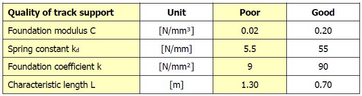
33
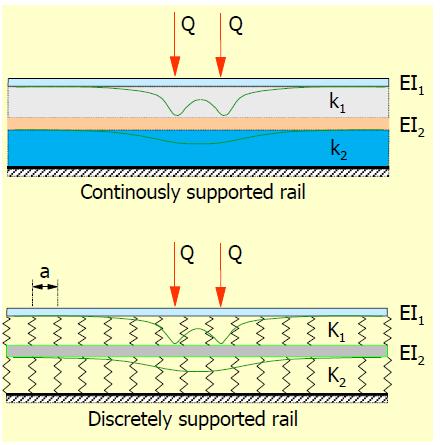
34 Double beam model The Zimmermann model is sufficient to understand the general behavior of the track structure. In some cases a more accurate description is necessary, for instance when the individual behavior of rail pads is investigated or if the effect of a slab foundation under the track is to be assessed. A more realistic model is the double beam model. For discrete supports with relatively high spacing a two-layer model can be used based on FEM techniques. For continuously supported track a two-layer model is useful, which actually is a generalization of the standard Zimmermann model. Both models, loaded for instance by two equal vertical forces, are drawn in the next figure with the characteristic deflection lines.
35
36 The upper beam in each model is the rail, whereas the other beam represents the continuity in the supporting structure which is mostly due to a slab track or other reinforcing structure. The model for the continuously supported rail is relatively simple and will be presented here. Without a distributed load on the rail the differential equations for this model are:
37 EI 1 *(d 4 w 1 /dx 4 )+k 1 *(w 1 w 2 )=0 EI 2 *(d 4 w 2 /dx 4 )+(k 1 +k 2 )*(w 2 k 1 *w 1 )=0
38 Dynamic amplification factor It is common practice to carry out a strength or fatigue calculation for a static load system, or often a single wheel load, using the longitudinal beam theory, according to which the dynamic effects are taken into account by a speed coefficient or dynamic amplification factor. The effect of running speed on load is in reality highly complex because of the dynamic interaction between vehicle and track. In view of the nature of the load, it is also more correct to carry out a fatigue calculation.
39 Several simple formulas have been proposed which aim to assess the dynamic rail stress. These formulas are a rough approximation of reality because the geometric quality of the track and the mechanical characteristics of the track and the vehicle are not sufficiently taken into account. One such empirical calculation scheme, which has been accepted by European railway companies, was developed by Eisenmann and is based on the following observations and assumptions:
40 Measurements on which this empirical method is based have shown that the stresses in the rail foot, from a statistical point of view, have a normal distribution as illustrated in the next figure; The mean value is independent of running speed V (studied up to 200 km/h) and can be determined with sufficient accuracy using Zimmermann s longitudinal beam calculation; The standard deviation is dependent on the running speed V and the state of the track.
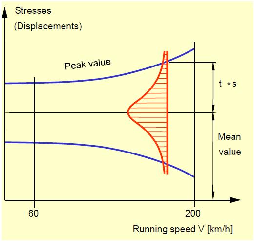
41
42 The Eisenmann scheme to determine the DAF (Dynamic Amplification Factor) is dependent on the train speed, the track quality, and chosen factor t and reads as follows: DAF- formula:
43 t = multiplication factor of standard deviation which depends on the confidence interval. Since the rail is so important for safety and reliability of rail traffic a value of 3 is recommended as the chance of exceeding the maximum calculated stresses is only 0.15%; ϕ = factor depending on track quality; V = train speed [km/h].

44 Values of t and ϕ factors
45 Maximum bending stress in rail foot center According to the Eisenmann method, the greatest expected dynamic bending tensile stress in the rail foot center can be determined from: σ max =DAF*σ mean
46 The mean value of the rail bending stress follows from : σ mean =M/W yf DAF = dynamic amplification factor M = bending moment [knm]; W yf = section modulus, relative to the rail foot [m³]
47
48 Railway superstructure calculation FEM method
49 The classical concepts of railway track analysis, such Beam on Elastic Foundation (BOEF), Winkler s theory or Zimmermann method are categorized as onedimensional analysis of a railway structure and are simplification of a beam laid on a continuous support (soil s subgrade or foundation). These methods are still very useful for analyzing a simple design and analysis of railway track systems. Unfortunately, for doing a complex analysis of a railway track, these methods have lack of capabilities, since they only take into account one dimensional system and neglect the actual discrete support provided by crossed sleeper, ballast, sub ballast mat and subgrade.
50 Nowadays, the use of computer software for doing Finite Element Method (FEM) or Finite Element Analysis (FEA) of a structure is very common for engineers. FEA consists of a huge amount of complex calculations; therefore, a manual calculation by hand is almost impossible to be done. Hence, the use of computer software will be very useful in this manner. The applications of FEM using software also widen in the field of railway infrastructure design and analysis. There are many advantages of using FEM method using computer. However, related to its complexities, one should understands the concepts and knows-how to solve the problems, to idealize the structure into FEM model in computer, and to choose the suitable elements and its behaviours, and also the correct method.
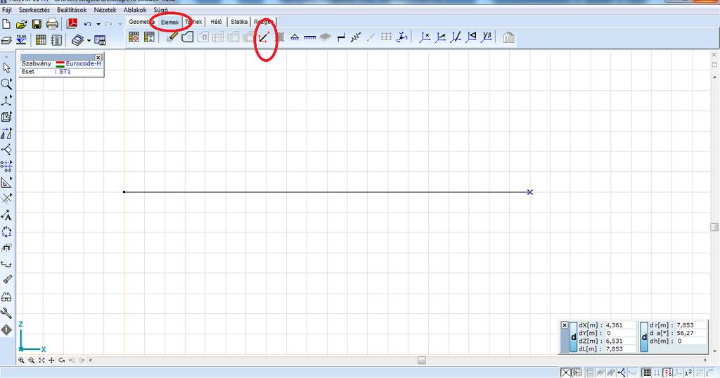
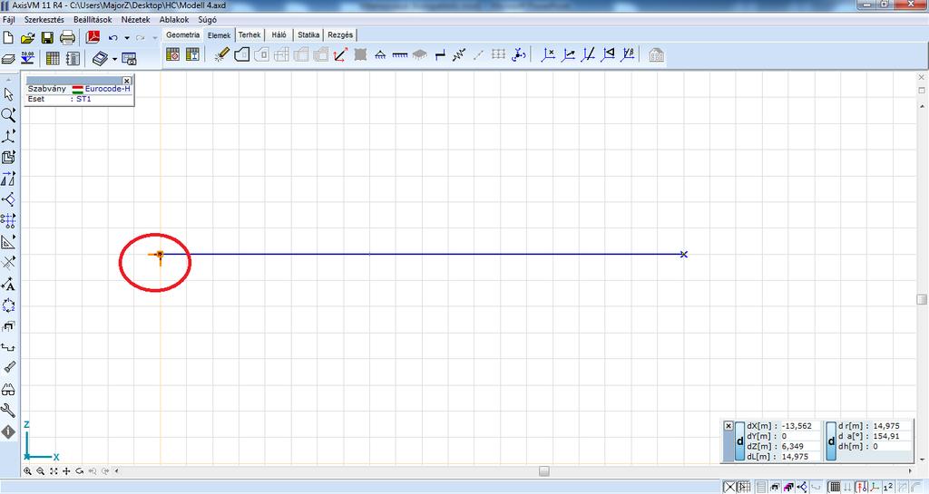
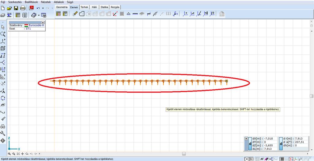
51 The FEM model E x I

52 Definition of the beam
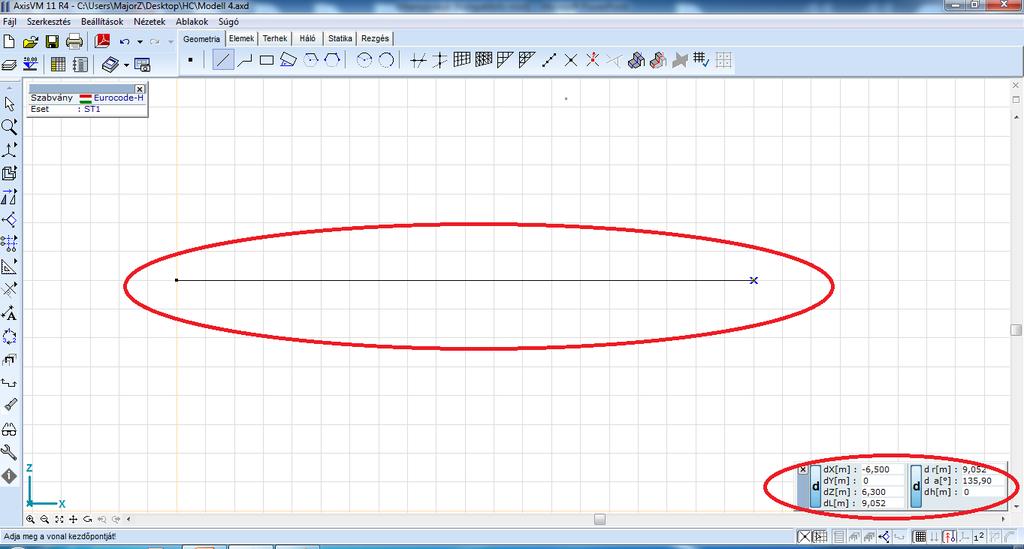
53
54
55

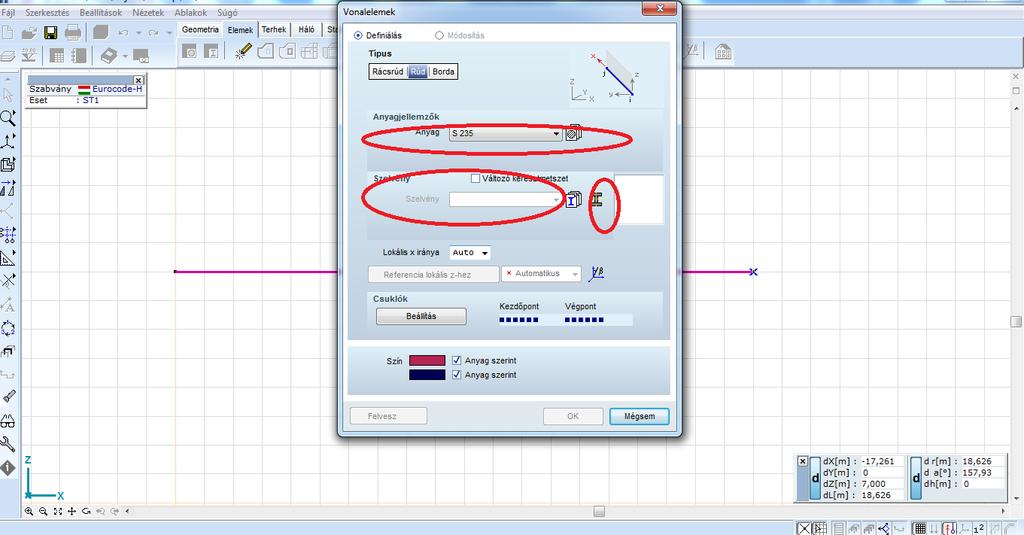
56 Definition of the cross-section
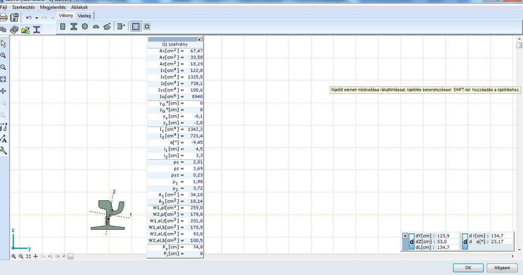
57

58 Definition of the supports
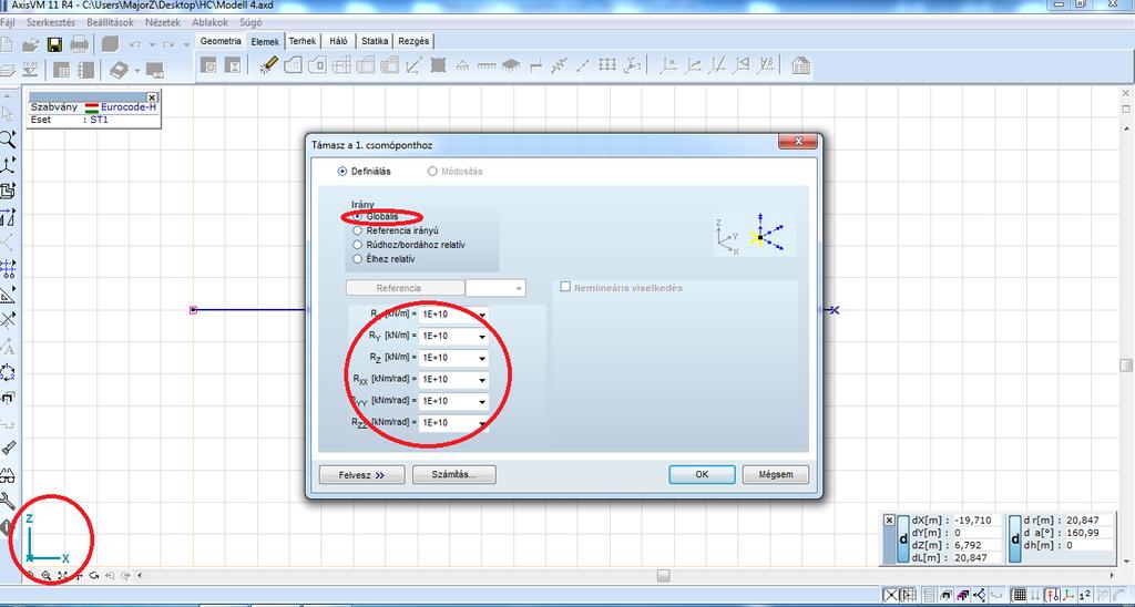
59
60
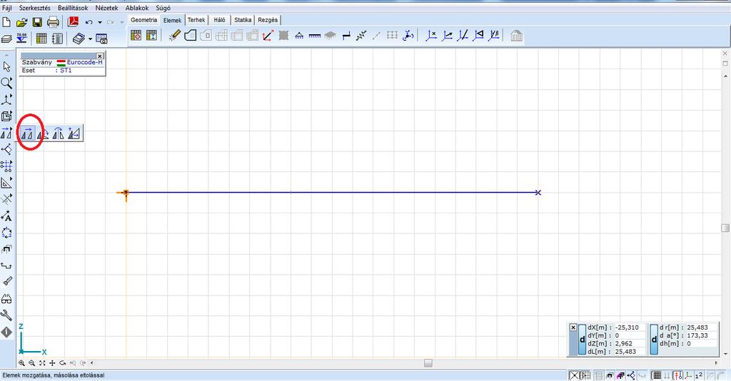
61
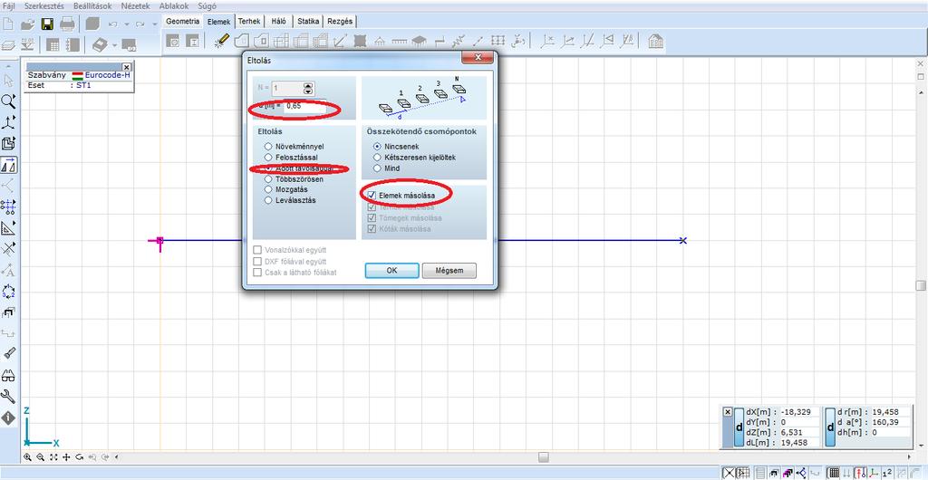
62
63

64 Definition of the loads
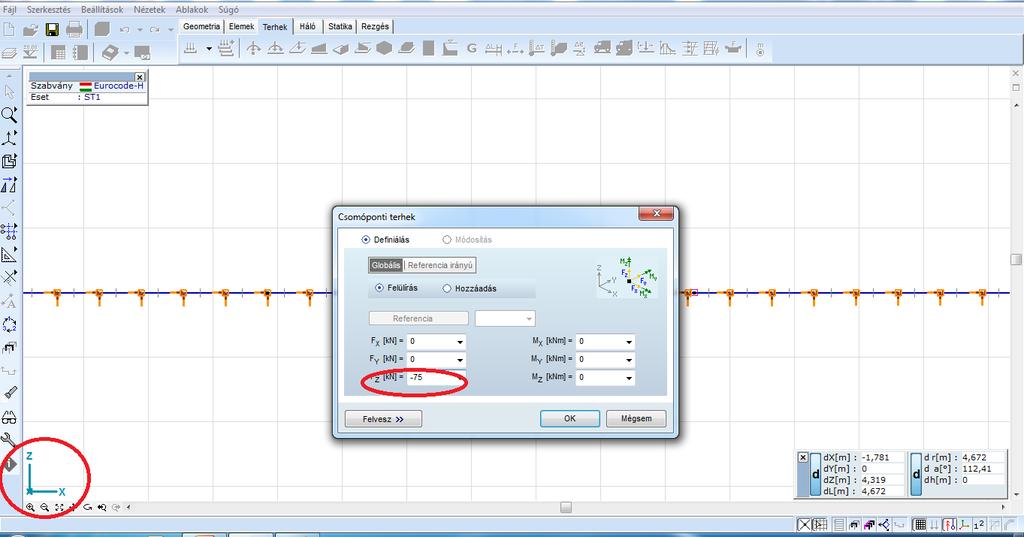
65
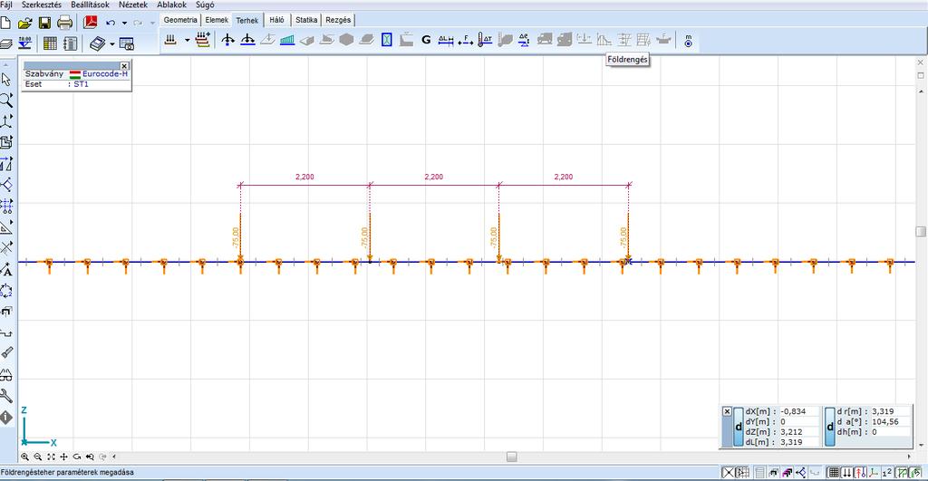
66
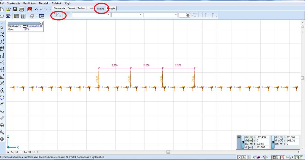
67 Calculation
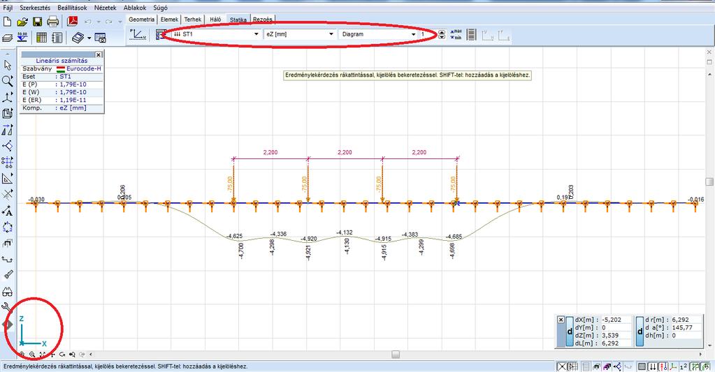
68 Results - deflection

69 Results - moments
70 REFERENCES Coenraad Esveld: Modern Railway Track Second Edition MRT-Productions, 2001, Zaltbommel
Numerical Analysis of Rail-Subgrade System
 Numerical Analysis of Rail-Subgrade System LUCACI Gheorghe Politehnica University of Timisoara, Civil Engineering Faculty, Ioan Curea 1, Timisoara, Romania, email: gheorghe.lucaci@ct.upt.ro Abstract:-
Dynamic analysis of rail track for high speed trains. 2D approach.
 Dynamic analysis of rail track for high speed trains. 2D approach. A. Gomes Correia & J. Cunha University of Minho, Department of Civil Engineering, Civil Engineering Centre, Guimarães, Portugal J. Marcelino
A PROCEDURE TO DETERMINE THE CRITICAL SPEED OF RAILWAY TRACKS BASED ON THE WINKLER'S HYPOTHESIS AND STATIC FEM SIMULATIONS
 6th European Conference on Computational Mechanics (ECCM 6) 7th European Conference on Computational Fluid Dynamics (ECFD 7) 11 15 June 2018, Glasgow, UK A PROCEDURE TO DETERMINE THE CRITICAL SPEED OF
FULL SCALE TESTS AND STRUCTURAL EVALUATION OF SOIL-STEEL FLEXIBLE CULVERTS FOR HIGH-SPEED RAILWAYS
 II European Conference BURIED FLEXIBLE STEEL STRUCTURES Rydzyna 3-4.4.1 FULL SCALE TESTS AND STRUCTURAL EVALUATION OF SOIL-STEEL FLEXIBLE CULVERTS FOR HIGH-SPEED RAILWAYS Andreas ANDERSSON*, Håkan SUNDQUIST**,
Effect of rail unevenness correlation on the prediction of ground-borne vibration from railways
 Effect of rail unevenness correlation on the prediction of ground-borne vibration from railways Evangelos Ntotsios; David Thompson Institute of Sound and Vibration Research, University of Southampton,
A NEW SAFETY PHILOSOPHY FOR CWR
 Coenraad Esveld Page 1 of 6 A NEW SAFETY PHILOSOPHY FOR CWR Coenraad Esveld Professor of Railway Engineering TU Delft From 1992 to 1997 the ERRI Committee D 202 carried out an extensive study on the behaviour
Investigation on dynamic behavior of railway track in transition zone
 Journal of Mechanical Science and Technology 25 (2) (2) 287~292 wwwspringerlinkcom/content/738494x DOI 7/s22622x Investigation on dynamic behavior of railway track in transition zone JabbarAli Zakeri *
Generation and Propagation of vibrations induced by high-speed railways
 Generation and Propagation of vibrations induced by high-speed railways João Manso Abstract In the years to come, Portugal has several challenges to overcome and one is to try to modernize its train network.
A STUDY ON THE WHEELSET/SLAB TRACK VERTICAL INTERACTION
 A STUDY ON THE WHEELSET/SLAB TRACK VERTICAL INTERACTION Associate Professor PhD. eng. Traian MAZILU Department of Railway Vehicles, University Politehnica of Bucharest 33 Splaiul Independentei, sector
Dynamic behaviour of a steel plate girder railroad bridge with rail joints
 Structures Under Shock and Impact XI 313 Dynamic behaviour of a steel plate girder railroad bridge with rail joints H. M. Kim 1, S. I. Kim 2 & W. S. Hwang 2 1 Department of Railroad Structure Research,
1 Introduction. Abstract
 Abstract This paper reports results from a numerical model to calculate subgrade settlement in railway tracks due to repeated dynamic loading. The trains are modelled as rigid body 2-axle carriages on
DETERMINING THE STRESS PATTERN IN THE HH RAILROAD TIES DUE TO DYNAMIC LOADS 1
 PERIODICA POLYTECHNICA SER. CIV. ENG. VOL. 46, NO. 1, PP. 125 148 (2002) DETERMINING THE STRESS PATTERN IN THE HH RAILROAD TIES DUE TO DYNAMIC LOADS 1 Nándor LIEGNER Department of Highway and Railway Engineering
Parametric Study of Thermal Stability on Continuous Welded Rail
 IJR International Journal of Railway Vol. 3, No. 4 / December 2010, pp. 126-133 The Korean Society for Railway arametric Study of Thermal Stability on Continuous Welded Rail Dong-Ho Choi* and Ho-Sung Na
Computational Simulation of Dynamic Response of Vehicle Tatra T815 and the Ground
 IOP Conference Series: Earth and Environmental Science PAPER OPEN ACCESS Computational Simulation of Dynamic Response of Vehicle Tatra T815 and the Ground To cite this article: Jozef Vlek and Veronika
NOISE & VIBRATION MITIGATION IN RAILWAY TRACK
 NOISE & VIBRATION MITIGATION IN RAILWAY TRACK Coenraad Esveld Esveld Consulting Services Emeritus Professor of Railway Engineering TU Delft 1 Noise: Rolling; Engines; Curves; Braking; Aerodynamics. Vibration:
CWR track vibration characteristics varying with the change of supporting condition
 Computers in Railways XIII 745 CWR track vibration characteristics varying with the change of supporting condition L. Li & Y. Luo Railway and Urban Mass Transit Research Institute, Tongji University, China
Lecture 15 Strain and stress in beams
 Spring, 2019 ME 323 Mechanics of Materials Lecture 15 Strain and stress in beams Reading assignment: 6.1 6.2 News: Instructor: Prof. Marcial Gonzalez Last modified: 1/6/19 9:42:38 PM Beam theory (@ ME
Experimental validation of a numerical model for the ground vibration from trains in tunnels
 Experimental validation of a numerical model for the ground vibration from trains in tunnels Qiyun Jin; David Thompson; Daniel Lurcock; Martin Toward; Evangelos Ntotsios; Samuel Koroma Institute of Sound
Indian railway track analysis for displacement and vibration pattern estimation
 Indian railway track analysis for displacement and vibration pattern estimation M. Mohanta 1, Gyan Setu 2, V. Ranjan 3, J. P. Srivastava 4, P. K. Sarkar 5 1, 3 Department of Mechanical and Aerospace Engineering,
Numerical prediction of track
 Numerical prediction of track settlement in railway turnouts Department of Applied Mechanics / CHARMEC Chalmers University of Technology Gothenburg, Sweden 15 Contents Objectives of CHARMEC TS15 Introduction
Edinburgh Research Explorer
 Edinburgh Research Explorer EVALUATING THE DYNAMIC BEHAVIOUR OF CONCRETE SLAB TRACK FOR HIGH SPEED RAIL USING NUMERICAL ANALYSIS Citation for published version: Forde, M, Zimele, L, De Bold, R & Ho, C
Fatigue Crack Analysis on the Bracket of Sanding Nozzle of CRH5 EMU Bogie
 Journal of Applied Mathematics and Physics, 2015, 3, 577-583 Published Online May 2015 in SciRes. http://www.scirp.org/journal/jamp http://dx.doi.org/10.4236/jamp.2015.35071 Fatigue Crack Analysis on the
Emission of Train-Induced Ground Vibration Prediction of Axle-Load Spectra and its Experimental Verification
 Emission of Train-Induced Ground Vibration Prediction of Axle-Load Spectra and its Experimental Verification Lutz Auersch BAM Federal Institute of Material Research and Testing, Unter den Eichen, Berlin,
This procedure covers the determination of the moment of inertia about the neutral axis.
 327 Sample Problems Problem 16.1 The moment of inertia about the neutral axis for the T-beam shown is most nearly (A) 36 in 4 (C) 236 in 4 (B) 136 in 4 (D) 736 in 4 This procedure covers the determination
Mechanistic Pavement Design
 Seminar on Pavement Design System and Pavement Performance Models Reykjavik, 22. 23. March, 2007 Mechanistic Pavement Design A Road to Enhanced Understanding of Pavement Performance Sigurdur Erlingsson
General elastic beam with an elastic foundation
 General elastic beam with an elastic foundation Figure 1 shows a beam-column on an elastic foundation. The beam is connected to a continuous series of foundation springs. The other end of the foundation
2 marks Questions and Answers
 1. Define the term strain energy. A: Strain Energy of the elastic body is defined as the internal work done by the external load in deforming or straining the body. 2. Define the terms: Resilience and
Vertical vibrations of composite bridge/track structure/high-speed train systems. Part 1: Series-of-types of steel-concrete bridges
 BULLETIN OF THE POLISH ACADEMY OF SCIENCES TECHNICAL SCIENCES, Vol. 62, No. 1, 2014 DOI: 10.2478/bpasts-2014-0018 Vertical vibrations of composite bridge/track structure/high-speed train systems. Part
International Journal of Advance Engineering and Research Development
 Scientific Journal of Impact Factor (SJIF): 4.72 International Journal of Advance Engineering and Research Development Volume 4, Issue 11, November -2017 Parametric Study on Response of Railway Tracks
STUDY OF EFFECTS OF VIBRATIONS CAUSED BY RAILWAY TRAFFIC TO BUILDINGS
 Bulletin of the Transilvania University of Braşov CIBv 2014 Vol. 7 (56) Special Issue No. 1-2014 STUDY OF EFFECTS OF VIBRATIONS CAUSED BY RAILWAY TRAFFIC TO BUILDINGS R. NERIŞANU 1 D. DRĂGAN 1 M. SUCIU
DYNAMIC CHARACTERISTICS STUDY AND VIBRATION CONTROL OF MODERN TRAM TRACK SYSTEM
 DYNAMIC CHARACTERISTICS STUDY AND VIBRATION CONTROL OF MODERN TRAM TRACK SYSTEM Zheyu Zhang, Anbin Wang, Jian Bai, Zhiqiang Wang Luoyang Ship Material Research Institute Format of Presentation 31 3 4 35
1 Static Plastic Behaviour of Beams
 1 Static Plastic Behaviour of Beams 1.1 Introduction Many ductile materials which are used in engineering practice have a considerable reserve capacity beyond the initial yield condition. The uniaxial
Introduction to Continuous Systems. Continuous Systems. Strings, Torsional Rods and Beams.
 Outline of Continuous Systems. Introduction to Continuous Systems. Continuous Systems. Strings, Torsional Rods and Beams. Vibrations of Flexible Strings. Torsional Vibration of Rods. Bernoulli-Euler Beams.
PURE BENDING. If a simply supported beam carries two point loads of 10 kn as shown in the following figure, pure bending occurs at segment BC.
 BENDING STRESS The effect of a bending moment applied to a cross-section of a beam is to induce a state of stress across that section. These stresses are known as bending stresses and they act normally
The present paper concentrates on the results of in situ vibration measurements performed within the
 EXPERIMENTAL RESULTS OF FREE FIELD AND STRUCTURAL VIBRATIONS DUE TO UNDERGROUND RAILWAY TRAFFIC P. Chatterjee a, G. Degrande a, S. Jacobs a, J. Charlier b, P. Bouvet b and D. Brassenx c a K.U.Leuven, Department
Railway induced ground vibration
 RIVAS Training Workshop 23/5/213, Die Schmiede, Berlin, Germany "Reducing railway induced ground vibration by interventions on the transmission path" Railway induced ground vibration Geert Lombaert, Stijn
Accuracy, and the prediction of ground vibration from underground railways Hugh Hunt 1 and Mohammed Hussein 2
 5 th Australasian Congress on Applied Mechanics, ACAM 2007 10-12 December 2007, Brisbane, Australia Accuracy, and the prediction of ground vibration from underground railways Hugh Hunt 1 and Mohammed Hussein
Final Exam Solution Dynamics :45 12:15. Problem 1 Bateau
 Final Exam Solution Dynamics 2 191157140 31-01-2013 8:45 12:15 Problem 1 Bateau Bateau is a trapeze act by Cirque du Soleil in which artists perform aerial maneuvers on a boat shaped structure. The boat
UNIVERSITA` DEGLI STUDI DI PADOVA
 UNIVERSITA` DEGLI STUDI DI PADOVA SCUOLA DI INGEGNERIA Dipartimento ICEA Corso di Laurea Magistrale in Ingegneria Civile TESI DI LAUREA SOIL-STRUCTURE INTERACTION: REVIEW OF THE FUNDAMENTAL THEORIES Relatore:
Rolf Diehl, Reinhard Gorlich and Georg Holzl 2 1 Introduction In the speed range from about 60 to about 250 km/h rolling noise is the dominant noise f
 Rolf Diehl, Reinhard Gorlich and Georg Holzl 1 Acoustic Optimisation of Railroad Track Using Computer Aided Methods Rolf Diehl and Reinhard Gorlich Muller{BBM GmbH, D{82152 Planegg, Robert-Koch-Str. 11
Track stiffness assessment. Abstract
 Track stiffness assessment Alain Robinet, Engineering Department, SNCF, France Email: alain.robinet@sncf.fr Mohsen Hosseingholian, Civil Engineering Department, University of Caen, France Email: mhosseingholian@yahoo.com
Lecture 2: Introduction to Uncertainty
 Lecture 2: Introduction to Uncertainty CHOI Hae-Jin School of Mechanical Engineering 1 Contents Sources of Uncertainty Deterministic vs Random Basic Statistics 2 Uncertainty Uncertainty is the information/knowledge
Finite Difference Dynamic Analysis of Railway Bridges Supported by Pasternak Foundation under Uniform Partially Distributed Moving Railway Vehicle
 , October 21-23, 2015, San Francisco, USA Finite Difference Dynamic Analysis of Railway Bridges Supported by Pasternak Foundation under Uniform Partially Distributed Moving Railway Vehicle M. C. Agarana
Stress Analysis Lecture 4 ME 276 Spring Dr./ Ahmed Mohamed Nagib Elmekawy
 Stress Analysis Lecture 4 ME 76 Spring 017-018 Dr./ Ahmed Mohamed Nagib Elmekawy Shear and Moment Diagrams Beam Sign Convention The positive directions are as follows: The internal shear force causes a
D : SOLID MECHANICS. Q. 1 Q. 9 carry one mark each.
 GTE 2016 Q. 1 Q. 9 carry one mark each. D : SOLID MECHNICS Q.1 single degree of freedom vibrating system has mass of 5 kg, stiffness of 500 N/m and damping coefficient of 100 N-s/m. To make the system
TMHL TMHL (Del I, teori; 1 p.) SOLUTION I. II.. III. Fig. 1.1
 SOLUTION I. II.. III. Fig. 1.1") TMHL61 2014-01-16 (Del I, teori; 1 p.) 1. Fig. 1.1 shows three cases of sharp cracks in a sheet of metal. In all three cases, the sheet is assumed to be very large in comparison with the crack. Note the
TMHL61 2014-01-16 (Del I, teori; 1 p.) 1. Fig. 1.1 shows three cases of sharp cracks in a sheet of metal. In all three cases, the sheet is assumed to be very large in comparison with the crack. Note the
DESIGN OF A HIGH SPEED TRAIN USING A MULTIPHYSICAL APPROACH
 DESIGN OF A HIGH SPEED TRAIN USING A MULTIPHYSICAL APPROACH Aitor Berasarte Technologies Management Area Technology Division CAF WHAT DO WE ANALYSE? AERODYNAMICS STRUCTURAL ANALYSIS DYNAMICS NOISE & VIBRATIONS
interaction and ground borne vibration Excitation mechanisms of train/track Structural Mechanics, Department of Civil Engineering, KU Leuven
 RIVAS Training Workshop 9//23, Hotel Bloom, Brussels, Belgium "Reducing railway induced ground vibration by controlling the source" Excitation mechanisms of train/track interaction and ground borne vibration
The Running Behaviour of an Elastic Wheelset
 The Running Behaviour of an Elastic Wheelset Ingo Kaiser German Aerospace Center (DLR) Oberpfaffenhofen, Institute of Robotics and Mechatronics Karl Popp University of Hannover, Institute of Mechanics
REGULATION OF THE DYNAMIC LIVE LOAD FAC- TOR FOR CALCULATION OF BRIDGE STRUCTURES ON HIGH-SPEED RAILWAY MAINLINES
 Vol. 13, Issue 1/2017, 12-19, DOI: 10.1515/cee-2017-0002 REGULATION OF THE DYNAMIC LIVE LOAD FAC- TOR FOR CALCULATION OF BRIDGE STRUCTURES ON HIGH-SPEED RAILWAY MAINLINES Leonid K. DYACHENKO 1,*, Andrey
Equivalent Dynamics Model of Ballasted Track Bed
 Master's Degree Thesis ISRN: BTH-AMT-EX--212/D-23--SE Equivalent Dynamics Model of Ballasted Track Bed Said Daoud Xie Guowei Liu Xiaoming Department of Mechanical Engineering Blekinge Institute of Technology
3. BEAMS: STRAIN, STRESS, DEFLECTIONS
 3. BEAMS: STRAIN, STRESS, DEFLECTIONS The beam, or flexural member, is frequently encountered in structures and machines, and its elementary stress analysis constitutes one of the more interesting facets
FINITE GRID SOLUTION FOR NON-RECTANGULAR PLATES
 th International Conference on Earthquake Geotechnical Engineering June 5-8, 7 Paper No. 11 FINITE GRID SOLUTION FOR NON-RECTANGULAR PLATES A.Halim KARAŞĐN 1, Polat GÜLKAN ABSTRACT Plates on elastic foundations
Beams. Beams are structural members that offer resistance to bending due to applied load
 Beams Beams are structural members that offer resistance to bending due to applied load 1 Beams Long prismatic members Non-prismatic sections also possible Each cross-section dimension Length of member
Modelling vibration from surface and underground railways as an evolutionary random process
 icccbe 010 Nottingham University Press Proceedings of the International Conference on Computing in Civil and Building Engineering W Tizani (Editor) Modelling vibration from surface and underground railways
M5 Simple Beam Theory (continued)
") M5 Simple Beam Theory (continued) Reading: Crandall, Dahl and Lardner 7.-7.6 In the previous lecture we had reached the point of obtaining 5 equations, 5 unknowns by application of equations of elasticity
M5 Simple Beam Theory (continued) Reading: Crandall, Dahl and Lardner 7.-7.6 In the previous lecture we had reached the point of obtaining 5 equations, 5 unknowns by application of equations of elasticity
Chapter 11. Displacement Method of Analysis Slope Deflection Method
 Chapter 11 Displacement ethod of Analysis Slope Deflection ethod Displacement ethod of Analysis Two main methods of analyzing indeterminate structure Force method The method of consistent deformations
Finite Element Analyses on Dynamic Behavior of Railway Bridge Due To High Speed Train
 Australian Journal of Basic and Applied Sciences, 6(8): 1-7, 2012 ISSN 1991-8178 Finite Element Analyses on Dynamic Behavior of Railway Bridge Due To High Speed Train Mehrdad Bisadi, S.A. Osman and Shahrizan
Introduction to Structural Member Properties
 Introduction to Structural Member Properties Structural Member Properties Moment of Inertia (I): a mathematical property of a cross-section (measured in inches 4 or in 4 ) that gives important information
PLAT DAN CANGKANG (TKS 4219)
") PLAT DAN CANGKANG (TKS 4219) SESI I: PLATES Dr.Eng. Achfas Zacoeb Dept. of Civil Engineering Brawijaya University INTRODUCTION Plates are straight, plane, two-dimensional structural components of which
PLAT DAN CANGKANG (TKS 4219) SESI I: PLATES Dr.Eng. Achfas Zacoeb Dept. of Civil Engineering Brawijaya University INTRODUCTION Plates are straight, plane, two-dimensional structural components of which
Roadway Grade = m, amsl HWM = Roadway grade dictates elevation of superstructure and not minimum free board requirement.
 Example on Design of Slab Bridge Design Data and Specifications Chapter 5 SUPERSTRUCTURES Superstructure consists of 10m slab, 36m box girder and 10m T-girder all simply supported. Only the design of Slab
Dynamic behaviour of transition zones in railways
 Dynamic behaviour of transition zones in railways B. E. Z. Coelho 1 Delft University of Technology, Delft, the Netherlands P. Hölscher Deltares, Delft, the Netherlands F. B. J. Barends Delft University
Quintic beam closed form matrices (revised 2/21, 2/23/12) General elastic beam with an elastic foundation
 General elastic beam with an elastic foundation") General elastic beam with an elastic foundation Figure 1 shows a beam-column on an elastic foundation. The beam is connected to a continuous series of foundation springs. The other end of the foundation
General elastic beam with an elastic foundation Figure 1 shows a beam-column on an elastic foundation. The beam is connected to a continuous series of foundation springs. The other end of the foundation
five Mechanics of Materials 1 ARCHITECTURAL STRUCTURES: FORM, BEHAVIOR, AND DESIGN DR. ANNE NICHOLS SUMMER 2017 lecture
 ARCHITECTURAL STRUCTURES: FORM, BEHAVIOR, AND DESIGN DR. ANNE NICHOLS SUMMER 2017 lecture five mechanics www.carttalk.com of materials Mechanics of Materials 1 Mechanics of Materials MECHANICS MATERIALS
DYNAMIC EFFECT OF HIGH SPEED RAILWAY TRAFFIC LOADS ON THE BALLAST TRACK SETTLEMENT
 Congresso de Métodos Numéricos em Engenharia 211 Coimbra, 14 a 17 de Junho 211 c APMTAC, Portugal 211 DYNAMIC EFFECT OF HIGH SPEED RAILWAY TRAFFIC LOADS ON THE BALLAST TRACK SETTLEMENT K. Nguyen, J. M.
New Insight into Track Modulus of ballasted Track
 New Insight into Track Modulus of ballasted Track Dipl. Ing. ETH Michael Kohler, Institut für Verkehrsplanung, Transporttechnik, Strassenund Eisenbahnbau ETH Zürich Conference paper STRC 2002 Session XXX
Effect of periodicity of railway track and wheel rail interaction on wheelset track dynamics
 Arch Appl Mech (2015) 85:1321 1330 DOI 10.1007/s00419-014-0981-4 SPECIAL RomanBogacz Włodzimierz Czyczuła Robert Konowrocki Effect of periodicity of railway track and wheel rail interaction on wheelset
Attenuation of rail vibration: Analysis of experimental data
 Attenuation of rail vibration: Analysis of experimental data A. Bracciali, F. Piccioli Dipartimento di Meccanica e Tecnologie Industriali Università di Firenze v. Santa Marta, 3 50139 Firenze e-mail: bracciali@ing.unifi.it
Fatigue Life Analysis Of Joint Bar Of Insulated Rail Joint
 Fatigue Life Analysis Of Joint Bar Of Insulated Rail Joint Washimraja Sheikh, Piyush M. Sirsat, Nakul K. Mahalle RTM Nagpur University, Priyadarshini College of Engineering, Assistant Professor, Department
Dynamic FE analysis of a continuous steel railway bridge and comparisons with field measurements
 Dynamic FE analysis of a continuous steel railway bridge and comparisons with field measurements G. Kaliyaperumal, B. Imam, T. Righiniotis & M. Chryssanthopoulos Faculty of Engineering and Physical Sciences,
2. Determine the deflection at C of the beam given in fig below. Use principal of virtual work. W L/2 B A L C
 CE-1259, Strength of Materials UNIT I STRESS, STRAIN DEFORMATION OF SOLIDS Part -A 1. Define strain energy density. 2. State Maxwell s reciprocal theorem. 3. Define proof resilience. 4. State Castigliano
Research Article Influence of Sleepers Shape and Configuration on Track-Train Dynamics
 Shock and Vibration, Article ID 393867, 7 pages http://dx.doi.org/10.1155/2014/393867 Research Article Influence of Sleepers Shape and Configuration on Track-Train Dynamics Roman Bogacz, 1,2 WBodzimierz
FINITE ELEMENTS METHOD IN ANALYSIS OF PROPAGATION OF VIBRATIONS WAVE IN THE SOIL
 Journal of KONES Powertrain and Transport, Vol. 18, No. 3 2011 FINITE ELEMENTS METHOD IN ANALYSIS OF PROPAGATION OF VIBRATIONS WAVE IN THE SOIL Jaros aw Bednarz, Jan Targosz AGH University of Science and
Assumptions: beam is initially straight, is elastically deformed by the loads, such that the slope and deflection of the elastic curve are
 *12.4 SLOPE & DISPLACEMENT BY THE MOMENT-AREA METHOD Assumptions: beam is initially straight, is elastically deformed by the loads, such that the slope and deflection of the elastic curve are very small,
 UNIT III DEFLECTION OF BEAMS 1. What are the methods for finding out the slope and deflection at a section? The important methods used for finding out the slope and deflection at a section in a loaded
International Journal of Advance Engineering and Research Development. Parametric Study of Beam Slab Raft Foundation
 Scientific Journal of Impact Factor (SJIF): 4.72 International Journal of Advance Engineering and Research Development Volume 4, Issue, May-2017 Parametric Study of Beam Slab Raft Foundation Sudhir.D.Ravani
Lateral load-deflection behaviour of single piles - An analysis of the small pile deflections
 Lateral load-deflection behaviour of single piles - An analysis of the small pile deflections Abderrazak Tharrafi 1, and Ali Bouafia 1,* 1 University Saâd Dahleb at Blida, Faculty of Technology, Dept.
A METHOD OF LOAD INCREMENTS FOR THE DETERMINATION OF SECOND-ORDER LIMIT LOAD AND COLLAPSE SAFETY OF REINFORCED CONCRETE FRAMED STRUCTURES
 A METHOD OF LOAD INCREMENTS FOR THE DETERMINATION OF SECOND-ORDER LIMIT LOAD AND COLLAPSE SAFETY OF REINFORCED CONCRETE FRAMED STRUCTURES Konuralp Girgin (Ph.D. Thesis, Institute of Science and Technology,
[8] Bending and Shear Loading of Beams
![[8] Bending and Shear Loading of Beams](/thumbs/92/110949676.jpg "[8] Bending and Shear Loading of Beams") [8] Bending and Shear Loading of Beams Page 1 of 28 [8] Bending and Shear Loading of Beams [8.1] Bending of Beams (will not be covered in class) [8.2] Bending Strain and Stress [8.3] Shear in Straight
[8] Bending and Shear Loading of Beams Page 1 of 28 [8] Bending and Shear Loading of Beams [8.1] Bending of Beams (will not be covered in class) [8.2] Bending Strain and Stress [8.3] Shear in Straight
P.E. Civil Exam Review:
 P.E. Civil Exam Review: Structural Analysis J.P. Mohsen Email: jpm@louisville.edu Structures Determinate Indeterminate STATICALLY DETERMINATE STATICALLY INDETERMINATE Stability and Determinacy of Trusses
Research on the Detecting System of High-speed Railway Wheel Defect based on Laser Method
 8th World Conference on Nondestructive Testing, 6- April, Durban, South Africa esearch on the Detecting System of High-speed ailway Wheel Defect based on Laser Method Yangkai, Pengchaoyong,Wangli,GaoxiaorongWangzeyong,Zhangyu,Pengjianping
Lecture 2: Stresses in Pavements
 Lecture 2: Stresses in Pavements Stresses in Layered Systems At any point, 9 stresses exist. They are 3 normal stresses (s z, s r, s t ) and 6 shearing stresses ( t rz = t zr, t rt = t tr, and t tz = t
Stress Analysis Lecture 3 ME 276 Spring Dr./ Ahmed Mohamed Nagib Elmekawy
 Stress Analysis Lecture 3 ME 276 Spring 2017-2018 Dr./ Ahmed Mohamed Nagib Elmekawy Axial Stress 2 Beam under the action of two tensile forces 3 Beam under the action of two tensile forces 4 Shear Stress
STRUCTURAL ANALYSIS CHAPTER 2. Introduction
 CHAPTER 2 STRUCTURAL ANALYSIS Introduction The primary purpose of structural analysis is to establish the distribution of internal forces and moments over the whole part of a structure and to identify
Design of reinforced concrete sections according to EN and EN
 Design of reinforced concrete sections according to EN 1992-1-1 and EN 1992-2 Validation Examples Brno, 21.10.2010 IDEA RS s.r.o. South Moravian Innovation Centre, U Vodarny 2a, 616 00 BRNO tel.: +420-511
Mechanical Design in Optical Engineering
 OPTI Buckling Buckling and Stability: As we learned in the previous lectures, structures may fail in a variety of ways, depending on the materials, load and support conditions. We had two primary concerns:
Chapter Objectives. Copyright 2011 Pearson Education South Asia Pte Ltd
 Chapter Objectives To generalize the procedure by formulating equations that can be plotted so that they describe the internal shear and moment throughout a member. To use the relations between distributed
FEA A Guide to Good Practice. What to expect when you re expecting FEA A guide to good practice
 FEA A Guide to Good Practice What to expect when you re expecting FEA A guide to good practice 1. Background Finite Element Analysis (FEA) has transformed design procedures for engineers. Allowing more
Development of Verification and Validation Procedures for Computer Simulation use in Roadside Safety Applications NCHRP 22-24
 Development of Verification and Validation Procedures for Computer Simulation use in Roadside Safety Applications NCHRP 22-24 PHENOMENA IMPORTANCE RANKING TABLES (PIRTS) Meeting Agenda 1:00-1:15 Introductions/Kick-off
Composite bridge design (EN1994-2) Bridge modelling and structural analysis
 Bridge modelling and structural analysis") EUROCODES Bridges: Background and applications Dissemination of information for training Vienna, 4-6 October 2010 1 Composite bridge design (EN1994-2) Bridge modelling and structural analysis Laurence
EUROCODES Bridges: Background and applications Dissemination of information for training Vienna, 4-6 October 2010 1 Composite bridge design (EN1994-2) Bridge modelling and structural analysis Laurence
Keywords: Track Deflection, Low Frequency Track Vibration, Train Loads, Dominant frequencies, Track Stiffness, Energy Harvesting
 1 Properties of train load frequencies and their applications D.R.M. Milne*, L.M. Le Pen, D.J. Thompson, W. Powrie Faculty of Engineering and the Environment, University of Southampton, Southampton SO17
Suggestion of Impact Factor for Fatigue Safety Assessment of Railway Steel Plate Girder Bridges
 Suggestion of Impact Factor for Fatigue Safety Assessment of Railway Steel Plate Girder Bridges 1 S.U. Lee, 2 J.C. Jeon, 3 K.S. Kyung Korea Railroad, Daejeon, Korea 1 ; CTC Co., Ltd., Gunpo, Kyunggi, Korea
BEAMS AND PLATES ANALYSIS
 BEAMS AND PLATES ANALYSIS Automotive body structure can be divided into two types: i. Frameworks constructed of beams ii. Panels Classical beam versus typical modern vehicle beam sections Assumptions:
Lecture-08 Gravity Load Analysis of RC Structures
 Lecture-08 Gravity Load Analysis of RC Structures By: Prof Dr. Qaisar Ali Civil Engineering Department UET Peshawar www.drqaisarali.com 1 Contents Analysis Approaches Point of Inflection Method Equivalent
However, reliability analysis is not limited to calculation of the probability of failure.
 Probabilistic Analysis probabilistic analysis methods, including the first and second-order reliability methods, Monte Carlo simulation, Importance sampling, Latin Hypercube sampling, and stochastic expansions
Calculation and analysis of internal force of piles excavation supporting. based on differential equation. Wei Wang
 International Conference on Energy and Environmental Protection (ICEEP 016) Calculation and analysis of internal force of piles excavation supporting based on differential equation Wei Wang School of Prospecting
Evaluation of Dynamic Properties of Trackbed Foundation Soil Using Mid-size Resonant Column Test
 IJR International Journal of Railway Vol. 6, No. 3 / September 03, pp. -9 The Korean Society for Railway Evaluation of Dynamic Properties of Trackbed Foundation Soil Using Mid-size Resonant Column Test
The Influence of Damping on Vibration Induced by High-Speed Trains
 The Influence of Damping on Vibration Induced by High-Speed Trains Z. Dimitrovová and J.N. Varandas UNIC, Department of Civil Engineering New University of Lisbon, Monte de Caparica, Portugal in B.H.V.
Modelling of Train Induced Vibration
 Modelling of Train Induced Vibration E. Ntotsios 1, S.G. Koroma 1, W.I. Hamad 2, D.J. Thompson 1, H.E.M. Hunt 2, J.P. Talbot 2, M.F.M. Hussein 3 1 ISVR, University of Southampton, United Kingdom 2 Engineering
Symmetric Bending of Beams
 Symmetric Bending of Beams beam is any long structural member on which loads act perpendicular to the longitudinal axis. Learning objectives Understand the theory, its limitations and its applications