NTC THERMISTORS General Characteristics... 2 Application Notes... 6 Selection Guide... 8 Ordering Code... 9
|
|
|
- Conrad Freeman
- 6 years ago
- Views:
Transcription
1 AVX NTC Thermistors
2 Contents NTC Thermistors NTC THERMISTORS General Characteristics Application Notes Selection Guide Ordering Code NTC SMD Thermistors NC 12 - NC With Nickel Barrier Termination NB 12 - NB With Nickel Barrier Termination NB 21 - NB Packaging Surface Mounting Guide NTC Accurate NJ 28 - NI 24 - NK 20 - NP NTC Disc Thermistors ND 03/06/09 - NE 03/06/09 - NV 06/ Packaging NTC Leadless Disc Thermistors NR Series for Consumer and Automotive Applications NTC Inrush Current Limiters Thermistors NF Application Guide Voltage-Current and Resistance-Temperature Characteristics Packaging Resistance Tables of Resistance vs Temperature Identification Traceability RoHS/ELV Compliance As we are anxious that our customers should benefit from the latest developments in the technology and standards, AVX reserves the right to modify the characteristics published in this brochure. NOTICE: Specifications are subject to change without notice. Contact your nearest AVX Sales Office for the latest specifications. All statements, information and data given herein are believed to be accurate and reliable, but are presented without guarantee, warranty, or responsibility of any kind, expressed or implied. Statements or suggestions concerning possible use of our products are made without representation or warranty that any such use is free of patent infringement and are not recommendations to infringe any patent. The user should not assume that all safety measures are indicated or that other measures may not be required. Specifications are typical and may not apply to all applications. 1
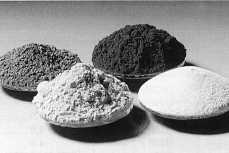
3 NTC Thermistors General Characteristics 1 INTRODUCTION NTC thermistors are thermally sensitive resistors made from a mixture of Mn, Ni, Co, Cu, Fe oxides. Sintered ceramic bodies of various sizes can be obtained. Strict conditions of mixing, pressing, sintering and metallization ensure an excellent batch-to-batch product characteristics. This semi-conducting material reacts as an NTC resistor, whose resistance decreases with increasing temperature. This Negative Temperature Coefficient effect can result from an external change of the ambient temperature or an internal heating due to the Joule effect of a current flowing through the thermistor. By varying the composition and the size of the thermistors, a wide range of resistance values (0.1Ω to 1MΩ) and temperature coefficients (-2 to -6% per C) can be achieved. RoHS (Restriction of Hazardous Substances - European Union directive 2002/95/EC). ELV (End of Life-Vehicle - European Union directive 2000/53/EC). All Thermistor Products have been fully RoHS/ELV since before Chip Thermistor NB RoHS/ELV Status: external Plating 100% smooth semi-bright Sn as standard SnPb Termination available on request. 2 MAIN CHARACTERISTICS 2.1 CHARACTERISTICS WITH NO DISSIPATION Nominal Resistance (Rn) The nominal resistance of an NTC thermistor is generally given at 25 C. It has to be measured at near zero power so that the resultant heating only produces a negligible measurement error. The following table gives the maximum advised measurement voltage as a function of resistance values and thermal dissipation factors. This voltage is such that the heating effect generated by the measurement current only causes a resistance change of 1% Rn/Rn. Ranges of Maximum measuring voltage values (V) (Ω) δ = 2 mw/ C δ = 5 mw/ C δ = 10 mw/ C δ = 20 mw/ C R < R < R 1, ,000 < R 10, ,000 < R 100, R < 100, Temperature - Resistance characteristics R (T) This is the relation between the zero power resistance and the temperature. It can be determined by experimental measurements and may be described by the ratios R (T) /R (25 C) where: R (T) is the resistance at any temperature T R (25 C) is the resistance at 25 C. These ratios are displayed on pages 36 to Temperature coefficient (α) The temperature coefficient ( ) which is the slope of the curve at a given point is defined by: 100 dr = and expressed in % per C. R dt Sensitivity index (B) The equation R = A exp (B/T) may be used as a rough approximation of the characteristic R (T). B is called the sensitivity index or constant of the material used. To calculate the B value, it is necessary to know the resistances R 1 and R 2 of the thermistor at the temperatures T 1 and T 2. 1 The equation: R 1 = R 2 exp B ( - 1 T 1 T 2 ) 1 R leads to: B (K) = n ( 1 ) 1 R ( T 1 T 2 ) Conventionally, B will be most often calculated for temperatures T 1 = 25 C and T 2 = 85 C ( K and K). In fact, as the equation R = A exp (B/T) is an approximation, the value of B depends on the temperatures T 1 and T 2 by which it is calculated. For example, from the R (T) characteristic of material M (values given on page 36), it can be calculated: B (25 85) = 3950 B (0 60) = 3901 B (50 110) = 3983 When using the equation R = A exp (B/T) for this material, the error can vary by as much as 9% at 25 C, 0.6% at 55 C and 1.6% at 125 C. Using the same equation, it is possible to relate the values of the index B and the coefficient α: 1 dr = 1 = A exp (B/T) R dt A exp (B/T) thus = B T 2 expressed in %/ C -B T 2 2
4 NTC Thermistors General Characteristics Further approximation of R (T) curve The description of the characteristic R (T) can be improved by using a greater number of experimental points, and by using the equation: 1 = A + B ( n R) + C ( n R) T 3 The parameters A, B and C are determined by solving the set of equations obtained by using the measured resistances at three temperatures. The solution of the above equation gives the resistance at any temperature: n R (T) = ( ) ( ( ) ()) 1 3 A- 1/T A- 1/T [ - 27 B C C C ( ) ( 27 3 A- 1/T 2+ 4 B ( ) () ) A- 1/T C The precision of this description is typically 0.2 C for the range 50 to +150 C (A, B, C being determined with experimental values at 20, +50 and 120 C) or even better if this temperature range is reduced. The ratios R(T)/R(25 C) for each of the different materials shown on pages 36 to 40 have been calculated using the above method Resistance tolerance and temperature precision An important characteristic of a thermistor is the tolerance on the resistance value at a given temperature. This uncertainty on the resistance (DR/R) may be related to the corresponding uncertainty on the temperature (DT), using the relationship: T = 100 R R 1 Example: consider the thermistor ND06M00152J R (25 C) = 1500 ohms Made from M material R (T) characteristic shown on page 23 gives: = - 4.4%/ C at 25 C Tolerance R/R = ±5% is equivalent to: T = 5%/4.4%/ C = ±1.14 C Resistance tolerance at any temperature Any material used for NTC manufacturing always displays a dispersion for the R (T) characteristic. This dispersion depends on the type of material used and has been especially reduced for our accuracy series thermistors. C C ] Thus, the tolerance on the resistance ( R 2 /R 2 ) at a temperature T 2 is the sum of two contributions as illustrated on Figure 1: the tolerance R 1 /R 1 at a temperature T 1 used as a reference. an additional contribution due to the dispersion on the characteristic R (T) which may be called Manufacturing tolerance (Tf). RΩ R 25 Figure 1 Differentiating the equation R = A exp (B/T), the two contributions on the tolerance at T can also be written: R 2 = R 1 + B R 2 R 1 Graph with B Graph with B ± B } ( R) 25 C } ( R) 25 C + 25 C T Temperature ( C) 1-1 T 1 T 2 The T(f) values given with the resistance temperature characteristics on pages 36 to 40 are based on a computer simulation using this equation and experimental values Designing the resistance tolerances Using the fact that the coefficient decreases with temperature (α = B/T 2 ), it is generally useful to define the closest tolerance of the thermistor at the maximum value of the temperature range where an accuracy in C is required. For example, let us compare the two designs 1 and 2 hereafter: } TF } = ( R) T T R α Design 1 Design 2 ( C) (Ω) (%/ C) R/R(%) T( C) R/R(%) T( C) Only the Design 2 is able to meet the requirement T 1 C from 25 C to 100 C. 3
5 NTC Thermistors General Characteristics Shaping of the R (T) characteristic By the use of a resistor network, it is possible to modify the R (T) characteristic of a thermistor so that it matches the required form, for example a linear response over a restricted temperature range. A single fixed resistor Rp placed in parallel with a thermistor gives a S shape resistance temperature curve (see Figure 2) which is substantially more linear at the temperature range around the inflexion point (Ro, To). R (kω) R TO R p R O T O Figure 2 Linearization of a thermistor It can be calculated that better linearization is obtained when the fixed resistor value and the mid-range temperature are related by the formula: B To Rp = R x To B+ 2To For example, with a thermistor ND03N00103J R 25 C = 10kΩ, B = 4080 K good linearization is obtained with a resistor in parallel where the value is: Rp = 10,000 Ω x = 8088 Ω (2 x 298) Demonstration of the R (T) parameters calculation To help our customers when designing thermistors for temperature measurement or temperature compensation, software developed by our engineering department is available upon request. R p T ( C) 2.2 CHARACTERISTICS WITH ENERGY DISSIPATION When a current is flowing through an NTC thermistor, the power due to the Joule effect raises the temperature of the NTC above ambient. The thermistor reaches a state of equilibrium when the power supplied becomes equal to the power dissipated in the environment. The thermal behavior of the thermistor is mainly dependent on the size, shape and mounting conditions. Several parameters have been defined to characterize these properties: Heat capacity (H) The heat capacity is the amount of heat required to change the temperature of the thermistor by 1 C and is expressed in J/ C Dissipation factor ( ) This is the ratio between the variation in dissipated power and the variation of temperature of the NTC. It is expressed in mw/ C and may be measured as: = U.I where U.I is the power necessary to raise to 85 C the temperature of a thermistor maintained in still air at 25 C Maximum permissible temperature (T max) This is the maximum ambient temperature at which the thermistor may be operated with zero dissipation. Above this temperature, the stability of the resistance and the leads attachment can no longer be guaranteed Maximum permissible power at 25 C (Pmax) This is the power required by a thermistor maintained in still air at 25 C to reach the maximum temperature for which it is specified. For higher ambient temperatures, the maximum permissible power is generally derated according to the Figure 3 hereafter and TL = Tmax 10 C. P max 25 TL Tmax T C Figure 3 Derating of maximum power 4
6 NTC Thermistors General Characteristics Voltage Current curves V (l) These curves describe the behavior of the voltage drop V measured across the NTC as the current l through the NTC is increased. They describe the state of equilibrium between power resulting from Joule effect and dissipated power in the surroundings. (Figure 4) V Vmax Io Figure 4 Voltage current curve V (l) Several zones can be identified: low current zone dissipated energy only produces negligible heating and the curve V (l) is almost linear. non-linear zone the curve V (l) displays a maximum voltage Vmax for a current lo.this maximum voltage Vmax and the temperature Tmax reached by the NTC under these conditions can be determined by using the equations: P = V 2 /R = (T - Tamb) and R = Ramb exp B (1/T - 1/Tamb) therefore: Tmax = B/2 - B 2 /4 - BT ~ amb T amb Vmax = (T max - T amb ) R amb exp [ B( 1-1 Tmax Tamb)] where is the dissipation factor and Tamb is the ambient temperature. high current zone for higher currents, an increase in temperature of the NTC decreases the resistance and the voltage more rapidly than the increase of the current. Above a certain dissipated power, the temperature of the NTC exceeds the permissible value Current Time curves l(t) When voltage is applied to a thermistor, a certain amount of time is necessary to reach the state of equilibrium described by the V(l) curves. This is the heating up time of the thermistor which depends on the voltage and the resistance on one side and the heat capacity and dissipation on the other. The curves l(t) are of particular interest in timing applications. I 1+T ( amb ) B Thermal time constant When a thermistor is self-heated to a temperature T above ambient temperature Tamb, and allowed to cool under zero power resistance, this will show a transient situation. At any time interval dt, dissipation of the thermistor ( (T Tamb)dt) generates a temperature decrease HdT, resulting in the equation: 1 dt = - dt (T - Tamb) H The solution to this equation for any value of t, measured from t = 0, is: n (T - T amb) = - t (To - Tamb) H We can define a thermal time constant as: = H/ expressed in seconds. Where the time t = : (T - Tamb) / (To - Tamb) = exp - 1 = expressing that for t =, the thermistor cools to 63.2% of the temperature difference between the initial To and Tamb (see Figure 5). According to IEC 539 our technical data indicates measured with To = 85 C, Tamb = 25 C and consequently T = 47.1 C. T ( C) t Figure 5 Temperature time curve T(t) t (s) Response time More generally, it is possible to define a response time as the time the thermistor needs to reach 63.2% of the total temperature difference when submitted to a change in the thermal equilibrium (for example from 60 C to 25 C in silicone oil 47V20 Rhodorsil). 5
7 NTC Thermistors Application Notes TEMPERATURE MEASUREMENT High sensitivity and low cost make NTC thermistors the most common device used for temperature measurement. Thermistor circuit Non-linearity of the R -T curve generally leads to the use of a resistor network to linearize the signal. An example is given in Figure 6. More precise measurements and temperature display can also be achieved with simple electronic equipment as shown in Figure 7. R2 R 3 A/D converter The choice of the model will particularly take into account the small size (better response time) and the resistance tolerance. Mounting conditions (dissipation), and input voltage (self-heating) will also be carefully defined to avoid serious errors in temperature measurement. R1 R NTC µ processor with R/T algorithm Display T C TEMPERATURE CONTROL AND ALARM NTC thermistors can be used as a simple on-off control temperature system or temperature alarm system. Figure 8 gives an example of such a circuit. When the temperature increases to a defined value, the resistance of the thermistor decreases and the current becomes sufficiently high to energize the relay and provide temperature alarm or heating system turn-off. The high sensitivity of thermistors (about 4% resistance change for 1 C) allows the temperature to be controlled very precisely. TEMPERATURE COMPENSATION As many electronic components (integrated circuits, amplifiers,...) have a positive temperature coefficient of resistance, NTC thermistors represent a cheap and interesting solution to compensate for this effect and provide an improved temperature stability for electronic equipment. It is necessary to include the thermistor in a resistor network (Figure 10) calculated in such a manner that the network coefficient compensates exactly for the positive temperature coefficient of the other component (Figure 9). Common leaded discs or chip thermistors are well suited for this application. Figure 6 Figure 7 R1 R2 R3 R NTC Figure 8 Resistance RC RTotal R C R R R NTC R NTC Temperature Figure 9 Figure 10 6
8 NTC Thermistors Application Notes LIQUID LEVEL OR FLOW DETECTION RS The dissipation of a thermistor is significantly different in a liquid or in a gas, in a static fluid or in a stirred one. A liquid level detector or a gas flow measurement can be designed using this property. In Figure 11, the output voltage measured on the thermistor depends upon the dissipation factor of its environment, and can be illustrated by V-l curves (Figure 12). This voltage can be used to detect the presence (V 2 ) or absence (V 1 ) of liquid around the thermistor or measure the flow speed. A good design should define a precise operating temperature range, where dissipation in the high dissipating medium at highest ambient temperature remains higher than the dissipation in low dissipating medium at lowest ambient temperature. V in V 2 V 1 Vin Voltage Figure 11 V RNTC SURGE PROTECTION k 2 k 1 A soft start of sensitive apparatus can be achieved by using NTC thermistors as described in Figures 13 and 14. At turn-on, the NTC absorbs the surge current, limits the current across the equipment and protects it. Then, the thermistor heats, its resistance decreases and most of the power becomes applied to the apparatus. In its design, the thermistor will be selected with a thermal capacity higher than the surge energy to absorb. This property is useful when using NTC thermistor as inrush current limiter for switching power supplies (see on page 29). Figure 12 Equipment Figure 13 V in/r S R NTC Current TIME DELAY The current-time characteristic of a thermistor is used in time delay applications such as delaying energization of a relay after application of power to an electrical circuit. The time delay, time necessary for the thermistor to heat up to the temperature where its resistance allows the current to reach the switching value of the relay, is mainly defined with the nominal resistance of the thermistor. The time delay is also strongly dependent upon the ambient temperature, as shown in Figure 15. Power Unprotected equipment Protected equipment NTC absorbed power Time Figure 14 Current T = 50 C T = 40 C T = 25 C Time Figure 15 7
9 NTC Thermistors Selection Guide Types Range of Values Main Applications Page R at 25 C SMD NC 12/20 10 Ω 1 MΩ - Hybrid circuit - Temperature 10 NB 12/20 Compensation 12 NB 21/23 14 Accuracy Series NJ 28 NI 24 NP 30 NK 20 2 kω 100 kω 2 kω 100 kω - Temperature measurement 19 Leaded Discs N.03 N.06 N Ω 1 MΩ 150 Ω 330 kω 68 Ω 150 kω - Temperature measurement and regulation - Level detection - Compensation 21 Leadless Discs NR Custom designed products generally defined at two temperatures - Automotive and industrial thermal control 27 NF 08 NF 10 NF 13 NF 15 NF 20 Inrush Current Limiters 5 Ω to 33 Ω 2.5 Ω to 120 Ω 2.5 Ω to 60 Ω 1.3 Ω to 47 Ω 2.5 Ω to 33 Ω - Current limitation - Delay circuit 29 8
10 NTC Thermistors Ordering Code HOW TO ORDER NC20 K M Type NC 12 NC 20 NB 12 NB 20 NB 21 NB 23 NJ 28 NI 24 NK 20 ND 03 ND 06 ND 09 Material Code I J K L M N P Q R S T U (See tables pages 36 to 40) Material Code 2nd Digit NJ, NK Types: A NB, NC Types: C or O or 5 or 2 Other Types: 0 Resistance at 25ºC (EIA Code) Tolerance on Resistance at 25 C F: ± 1% G: ± 2% H: ± 3% J: ± 5% K: ± 10% L: ± 15% M: ± 20% X: ± 25% Suffix NR.. 1. Resistance expressed by two significant figures 1st digit: 0 (zero) 2nd and 3rd digits: the first two significant figures of the resistance value at 25 C. 4th digit: for values 10 Ω: the number of ZEROS to be added to the resistance value for values 1 Ω and 9.9 Ω: the numerical 9 signifying that the resistance value is to be multiplied by 0.1 for values < 1 Ω: the numerical 8 signifying that the resistance value is to be multiplied by 0.01 Examples: 1000 Ω: Ω: Ω: Resistance expressed by three significant figures 1st, 2nd and 3rd digits: the first three significant figures of the resistance value at 25 C. 4th digit: for values > 100 Ω: the number of ZEROS to be added to the resistance value for values > 10 Ω and < 100 Ω: the numerical 9 signifying that the resistance value is to be multiplied by 0.01 for values > 1 Ω and < 10 Ω: the numerical 8 signifying that the capacitance value is to be multiplied by 0.01 Examples : 196 Ω: Ω: 4729 For leadless discs (types NR) see specification and ordering code on pages 28 and 29. 9
11 NTC SMD Thermistors NC 12 NC 20 Chip thermistors are a high quality and low cost device especially developed for surface mounting applications. They are widely used for temperature compensation but can also achieve temperature control of printed circuits. Its silver - palladium - platinum metallization provides a high degree of resistance to dewetting of the terminations during soldering (typically 260 C / 30 s). Types NC 12 NC 20 IEC SIZE : 0805 IEC SIZE : 1206 DIMENSIONS: millimeters (inches) 2 (.079) ± 0.3 (.012) 1.25 (.049) ± 0.2 (.008) 0.5 (.020) (.051) 0.2 (.008) min 0.2 (.008) min 1.6 (.063) ± 0.25 (.010) 0.5 (.020) (.059) 3.2 (.126) ± 0.4 (.016) 0.2 (.008) min 0.2 (.008) min Terminations Silver palladium platinum metallization Marking On packaging only Climatic category 40/125/56 Operating temperature -55 C to +150 C Tolerance on Rn (25 C) ±5%, ±10%, ±20% Maximum dissipation at 25 C 0.12 W 0.24 W Thermal dissipation factor 2 mw/ C 4 mw/ C Thermal time constant 5 s 7 s Resistance - Temperature characteristics: pages 36 to 40. APPLICATIONS LCD compensation Battery packs Mobile phones CD players Heating systems Air-conditioning systems Temperature control of Switch Mode Power Supplies Compensation of pressure sensors Protection of power transistors in various electronic circuits HOW TO ORDER NC 20 K M BA 10 Type Material Code K (See tables pages 11, 36-40) Resistance 10,000 Ω Tolerance M (±20%) J (±5%) K (±10%) Suffix: Packaging : Bulk BA: Plastic tape (180mm diam. reel) BE: Plastic tape (1/2 reel) BC: Plastic tape (330mm diam. reel) BB: Cardboard tape (180mm diam. reel) BF: Cardboard tape (1/2 reel) BD: Cardboard tape (330mm diam. reel)
12 NTC SMD Thermistors NC 12 NC 20 TABLE OF VALUES Types NC 12 IEC SIZE : 0805 Rn at 25 C Material B (K) at 25 C (1) ± 5% (Ω) Code ( B/B (2) ± 3% ) (%/ C) NC 12 KC NC 12 KC NC 12 KC NC 12 KC NC 12 KC KC 3470 ± 5% 3.9 NC 12 KC NC 12 KC NC 12 KC NC 12 KC NC 12 KC NC 12 MC NC 12 MC NC 12 MC NC 12 MC NC 12 MC NC 12 MC NC 12 MC NC 12 MC NC 12 MC MC 3910 ± 3% 4.4 NC 12 MC NC 12 MC NC 12 MC ,000 NC 12 MC ,200 NC 12 MC ,500 NC 12 MC ,800 NC 12 MC ,200 NC 12 MC ,700 NC 12 MC ,300 NC 12 J ,300 NC 12 J ,900 J 3480 ± 3% 3.9 NC 12 J ,700 NC 12 J ,600 NC 12 K ,800 NC 12 K ,200 K 3630 ± 3% 4.0 NC 12 K ,000 NC 12 K ,000 NC 12 L ,000 NC 12 L ,000 L 3790 ± 3% 4.2 NC 12 M ,000 NC 12 M ,000 M 3950 ± 3% 4.4 NC 12 M ,000 NC 12 M ,000 NC 12 N ,000 NC 12 N ,000 N 4080 ± 3% 4.6 NC 12 L ,000 L ± 3% 4.1 NC 12 N ,000 N 4080 ± 3% 4.6 NC 12 P ,000 NC 12 P ,000 P 4220 ± 3% 4.7 NC 12 P ,000 NC 12 P ,000 NC 12 Q ,000 Q 4300 ± 3% -4.7 NC 20 IEC SIZE : 1206 Types Rn at 25 C Material B (K) at 25 C (1) ± 5% (Ω) Code ( B/B (2) ± 3% ) (%/ C) NC 20 KC NC 20 KC NC 20 KC NC 20 KC NC 20 KC NC 20 KC KC 3470 ± 5% 3.9 NC 20 KC NC 20 KC NC 20 KC NC 20 KC NC 20 KC NC 20 KC NC 20 KC NC 20 MC NC 20 MC NC 20 MC NC 20 MC NC 20 MC NC 20 MC NC 20 MC MC 3910 ± 3% 4.4 NC 20 MC NC 20 MC NC 20 MC NC 20 MC NC 20 MC ,000 NC 20 MC ,200 NC 20 MC ,500 NC 20 I ,800 NC 20 I ,200 NC 20 I ,700 I 3250 ± 5% 3.7 NC 20 I ,300 NC 20 J ,900 NC 20 J ,700 J 3480 ± 3% 3.9 NC 20 J ,600 NC 20 J ,800 NC 20 K ,200 NC 20 K ,000 K 3630 ± 3% 4.0 NC 20 K ,000 NC 20 K ,000 NC 20 L ,000 NC 20 L ,000 L 3790 ± 3% 4.2 NC 20 M ,000 NC 20 M ,000 M 3950 ± 3% 4.4 NC 20 M ,000 NC 20 M ,000 NC 20 N ,000 NC 20 N ,000 N 4080 ± 3% 4.6 NC 20 N ,000 NC 20 N ,000 NC 20 P ,000 NC 20 P ,000 P 4220 ± 3% 4.7 NC 20 P ,000 NC 20 P ,000 NC 20 Q ,000 NC 20 Q ,000 Q 4300 ± 3% 4.7 NC 20 Q ,000 NC 20 Q ,000 NC 20 R ,000 NC 20 R ,000 R 4400 ± 3% 4.8 NC 20 R ,000 NC 20 R ,000,000 11
13 NTC SMD Thermistors With Nickel Barrier Termination NB 12 - NB 20 Chip thermistors are high quality and low cost devices especially developed for surface mounting applications. They are widely used for temperature compensation but can also achieve temperature control of printed circuits. A nickel barrier metallization provides outstanding qualities of solderability and enables this chip to meet the requirements of the most severe soldering processes. Types NB 12 NB 20 IEC SIZE : 0805 IEC SIZE : 1206 DIMENSIONS: millimeters (inches) 2 (.079) ± 0.3 (.012) 1.25 (.049) ± 0.2 (.008) 0.5 (.020) (.051) 0.2 (.008) min 0.2 (.008) min 1.6 (.063) ± 0.25 (.010) 0.5 (.020) (.059) 3.2 (.126) ± 0.4 (.016) 0.2 (.008) min 0.2 (.008) min Terminations Nickel Barrier Marking On packaging only Climatic category 40/125/56 Operating temperature -55 C to +150 C Tolerance on Rn (25 C) ±5%, ±10%, ±20% Maximum dissipation at 25 C 0.12 W 0.24 W Thermal dissipation factor 2 mw/ C 4 mw/ C Thermal time constant 5 s 7s Resistance - Temperature characteristics: pages 36 to 40. APPLICATIONS LCD compensation Battery packs Mobile phones CD players Heating systems Air-conditioning systems Temperature control of Switch Mode Power Supplies Compensation of pressure sensors Protection of power transistors in various electronic circuits HOW TO ORDER NB 20 K M BA 12 Type Material Code K (See tables page 13) Resistance 10,000 Ω Tolerance M (±20%) J (±5%) K (±10%) Suffix: Packaging : Bulk BA: Plastic tape (180mm diam. reel) BE: Plastic tape (1/2 reel) BC: Plastic tape (330mm diam. reel) BB: Cardboard tape (180mm diam. reel) BF: Cardboard tape (1/2 reel) BD: Cardboard tape (330mm diam. reel)
14 NTC SMD Thermistors With Nickel Barrier Termination NB 12 NB 20 TABLE OF VALUES NB 12 IEC SIZE : 0805 Types Rn at 25 C Material B (K) at 25 C (Ω) Code (1) ± 5% ( B/B ) (%/ C) (2) ± 3% NB 12 KC NB 12 KC NB 12 KC NB 12 KC NB 12 KC KC 3470 ± 5% 3.9 NB 12 KC NB 12 KC NB 12 KC NB 12 KC NB 12 KC NB 12 MC NB 12 MC NB 12 MC NB 12 MC NB 12 MC NB 12 MC NB 12 MC NB 12 MC NB 12 MC MC 3910 ± 3% 4.4 NB 12 MC NB 12 MC NB 12 MC ,000 NB 12 MC ,200 NB 12 MC ,500 NB 12 MC ,800 NB 12 MC ,200 NB 12 MC ,700 NB 12 MC ,300 NB 12 J ,300 NB 12 J ,900 J 3480 ± 3% 3.9 NB 12 J ,700 NB 12 J ,600 NB 12 K ,800 NB 12 K ,200 K 3630 ± 3% 4.0 NB 12 K ,000 NB 12 L ,000 NB 12 L ,000 L 3790 ± 3% 4.2 NB 12 M ,000 NB 12 M ,000 M 3950 ± 3% 4.4 NB 12 M ,000 NB 12 M ,000 NB 12 N ,000 NB 12 N ,000 N 4080 ± 3% 4.6 NB 12 N ,000 NB 12 L ,000 L ± 3% 4.1 NB 12 N ,000 NB 12 N ,000 N ± 3% 4.7 NB 12 P ,000 P 4220 ± 3% 4.7 NB 12 SC ,000 SC 4500 ± 3% 4.8 NB 12 P ,000 NB 12 P ,000 P 4220 ± 3% 4.7 NB 12 P ,000 NB 12 Q ,000 NB 12 Q ,000 Q 4300 ± 3% 4.7 NB 12 R ,000,000 R 4400 ± 3% 4.8 NB 20 IEC SIZE : 1206 Types Rn at 25 C Material B (K) at 25 C (Ω) Code (1) ± 5% ( B/B ) (%/ C) (2) ± 3% NB 20 MC MC 3910 ± 3% 4.4 NB 20 MC ,000 MC 3910 ± 3% 4.4 NB 20 J ,700 NB 20 J ,600 J 3480 ± 3% 3.9 NB 20 J ,800 NB 20 J ,200 J ± 3% 3.9 NB 20 K ,000 NB 20 K ,000 K 3630 ± 3% 4.0 NB 20 L ,000 NB 20 L ,000 L 3790 ± 3% 4.2 NB 20 L ,000 NB 20 M ,000 NB 20 M ,000 M 3950 ± 3% 4.4 NB 20 M ,000 NB 20 M ,000 NB 20 N ,000 NB 20 N ,000 N 4080 ± 3% 4.6 NB 20 N ,000 NB 20 N ,000 N ± 3% 4.7 NB 20 P ,000 NB 20 P ,000 NB 20 P ,000 P 4220 ± 3% 4.7 NB 20 P ,000 NB 20 Q ,000 NB 20 Q ,000 NB 20 Q ,000 Q 4300 ± 3% 4.7 NB 20 Q ,000 NB 20 Q ,000 NB 20 R ,000 NB 20 R ,000 R 4400 ± 3% 4.8 NB 20 R ,000,000 13
15 NTC SMD Thermistors With Nickel Barrier Termination NB 21 - NB 23 Chip thermistors are high quality and low cost devices especially developed for surface mounting applications. They are widely used for temperature compensation but can also achieve temperature control of printed circuits. A nickel barrier metallization provides outstanding qualities of solderability and enables this chip to meet the requirements of the most severe soldering processes. Types NB 21 NB 23 IEC SIZE : 0603 IEC SIZE : 0402 DIMENSIONS: millimeters (inches) 1.6 (.063) 0.2 (.008) 0.8 (.031) ±0.2 (.008) 0.8 (.031) ±0.2 (.008) 0.2 (.008) min 0.2 (.008) min 0.40 ± 0.1 (0.02 ±0.004) 0.60 (0.024) max 1.0 ± 0.1 (0.04 ± 0.004) 0.25 (0.10) min 0.25 (0.10) min Terminations Nickel Barrier Marking On packaging only Climatic category 40/125/56 Operating temperature -55 C to +150 C Tolerance on Rn (25 C) ±5%, ±10%, ±20% Maximum dissipation at 25 C 0.07 W 0.06 W Thermal dissipation factor 1 mw/ C 0.8 mw/ C Thermal time constant 4 s 3 s Resistance - Temperature characteristics: pages 36 to 40. APPLICATIONS LCD compensation Battery packs Mobile phones CD players Heating systems Air-conditioning systems Temperature control of Switch Mode Power Supplies Compensation of pressure sensors Protection of power transistors in various electronic circuits HOW TO ORDER NB 21 K M BB Type Material Code K (See tables page 15) Resistance 10,000 Ω Tolerance M (±20%) J (±5%) K (±10%) Suffix: Packaging : Bulk BB: Cardboard tape (180mm diam. reel) BF: Cardboard tape (1/2 reel) BD: Cardboard tape (330mm diam. reel) 14
16 NTC SMD Thermistors With Nickel Barrier Termination NB 21 - NB 23 TABLE OF VALUES Types NB 21 IEC SIZE : 0603 Rn at 25 C Material B (K) at 25 C (1) ± 5% (Ω) Code ( B/B (2) ± 3% ) (%/ C) NB 21 KC NB 21 KC KC 3470 ± 5% 3.9 NB 21 KC NB 21 MC ,000 MC 3910 ± 3% 4.4 NB 21 J ,700 J 3480 ± 3% 3.9 NB 21 J , ± 3% 3.9 NB 21 J ,000 J ± 3% 3.9 NB 21 K ,000 NB 21 K ,000 K 3630 ± 3% 4.0 NB 21 L ,000 L 3790 ± 3% 4.2 NB 21 M ,000 M 3950 ± 3% 4.4 NB 21 M ,000 NB 21 L ,000 L ± 3% 4.1 NB 21 N ,000 N 4080 ± 3% 4.6 NB 21 N ,000 N ± 3% 4.7 NB 21 P ,000 P 4220 ± 3% 4.7 NB 21 Q ,000 Q 4300 ± 3% 4.7 NB 21 Q ,000 Types NB 23 IEC SIZE : 0402 Rn at 25 C Material B (K) at 25 C (1) ± 5% (Ω) Code ( B/B (2) ± 3% ) (%/ C) NB 23 NC ,000 NC 4080 ± 3% 4.6 NB 23 RC ,000 RC 4340 ± 3% 4.7 NB 23 NC ,000 NB 23 NC ,000 NC 4080 ± 3% 4.6 NB 23 RC ,000 NB 23 RC ,000 RC 4340 ± 3% 4.7 NB 23 NE ,000 NE 4100 ± 3% 4.6 NB 23 RC ,000 NB 23 RC ,000 RC 4340 ± 3% 4.7 NB 23 RC ,000 15
17 Packaging for Automatic Insertion NTC Chip Thermistors / NC/NB Series AUTOMATIC INSERTION Super 8 Plastic Tape Packaging: The mechanical and dimensional reel characteristics are in accordance with the IEC publication (.217) ±0.2 (.008) Cover Tape Max 3 B0 B1 Max 3 30µ ± 5µ T K R = 0.3 (.012) Max. Max 3 D0 A1 Hole P2 Max 3 A (.008) 1 (.039) -0 P0 F E Direction of unreeling W Designation Symbol Value Tolerance Tape width W 8 ±0.2 Tape thickness T 0.4 max. Pitch of the sprocket holes P0 4 ±0.1 Diameter of the sprocket holes D0 1.5 ±0.1-0 Distance E 1.75 ±0.1 Distance (center to center) F 3.5 ±0.05 Distance (center to center) P2 2 ±0.1 Sizes of the NC 12 (0805) A0 1.5 ±0.1 cavities B0 2.4 ±0.1 K 1.4 max. K ±0.1 (size is adjustable) (K = t1 +0.2) NC 20 (1206) A ±0.1 B ±0.1 K 1.5 max. K ±0.1 (size is adjustable) (K = t1 +0.2) ø180 (7.09) (.079) ø 62 (2.44) ± 1.5 (.059) 14.4 (.567) max. 8.4 (.331) (.006) (.020) ø 20.5 (.087) (.006) ø (.502) - 0 Reel according to ISO/DIS Direction of unreeling Bottom side Reel Upper side QUANTITY PER REEL Type Suffix Qty Per Reel NC - NB 12 BA 4000 BE 2000 NC 20 - NB 20 BA 3000 BE
18 Packaging for Automatic Insertion NTC Chip Thermistors / NC/NB Series AUTOMATIC INSERTION 8mm Paper Tape Packaging: The mechanical and dimensional reel characteristics are in accordance with the IEC publication T D 0 P 2 P 0 10 PITCHES CUMULATIVE TOLERANCE ON TAPE 0.20mm (0.008) E 1 BOTTOM COVER TAPE TOP COVER TAPE B 0 F E 2 W G T 1 T 1 CAVITY SIZE SEE NOTE 1 A0 CENTER LINES OF CAVITY P 1 User Direction of Feed Designation Symbol Value Tolerance Tape width W /+0.3 Tape thickness T 1.1 max. Pitch of the sprocket holes P0 4 ±0.1 Diameter of the sprocket holes 1.5 D0-0/+0.1 ±0.1 Distance E ±0.1 Distance (center to center) F 3.5 ±0.05 Distance (center to center) P2 2 ±0.05 Cover tape thickness T max. Distance E min. Distance G 0.75 min. Component pitch 0805/ ±0.1 P ±0.1 ø180 (7.09) (.079) ø 62 (2.44) ± 1.5 (.059) 14.4 (.567) max. 8.4 (.331) (.006) (.020) ø 20.5 (.087) (.006) ø (.502) - 0 Reel according to ISO/DIS Direction of unreeling Bottom side Reel Upper side QUANTITY PER REEL Type Suffix Qty Per Reel NB - NC 12 BB 4000 NB 21 BF 2000 NB 23 BB BF
19 Surface Mounting Guide Chip Thermistor Application Notes STORAGE Wave Good solderability is maintained for at least twelve months, provided the components are stored in their as received packaging at less than 40 C and 70% RH Preheat Natural Cooling SOLDERABILITY / LEACHING Terminations to be well soldered after immersion in a 60/40 tin/lead solder bath at 235 ± 5 C for 2 ± 1 seconds. Terminations will resist leaching for at least the immersion times and conditions recommendations shown below. Solder Temp T 230ºC to 250ºC P/N Termination Solder Solder Immersion Type Tin/Lead Temp ºC Time Seconds NC AgPdPt 60/ ± 5 15 max NB Nickel Barrier 60/ ± 5 30 ± 1 NB products are compatible with a wide range of soldering conditions consistent with good manufacturing practice for surface mount components. This includes Pb free reflow processes with peak temperatures up to 270ºC. Recommended profiles for reflow and wave soldering are shown below for reference. NC products are recommended for lead soldering application or gluing techniques. 0 1 to 2 min 3 sec. max (Preheat chips before soldering) T/maximum 150 C a) The visual standards used for evaluation of solder joints will need to be modified as lead free joints are not as bright as with tin-lead pastes and the fillet may not be as large. b) Resin color may darken slightly due to the increase in temperature required for the new pastes. c) Lead-free solder pastes do not allow the same self alignment as lead containing systems. Standard mounting pads are acceptable, but machine set up may need to be modified. Reflow D2 Solder Temp Preheat 220ºC to 250ºC Natural Cooling RECOMMENDED SOLDERING PAD LAYOUT Dimensions in mm (inches) REFLOW SOLDERING D1 D3 D4 D5 Temperature C min 1min (Minimize soldering time) 10 sec. max Pre-heating: 150 C ±15 C / 60-90s Max. Peak Gradient: 2.5 C/s Peak Temperature: 245 C ±5 C Time at >230 C: 40s Max. Time (s) Case Size P/N D1 D2 D3 D4 D NB (.067) (.024) (.020) (.024) (.020) 0603 NB (.091) (.031) (.028) (0.31) (.030) 0805 NB (.118) (.039) (.039) (.039) (.049) 1206 NB (.157) (.039) (.079) (.039) (.098) WAVE SOLDERING Case Size P/N D1 D2 D3 D4 D NB (.122) (.047) (.028) (.047) (.030) 0805 NB (.157) (.059) (.039) (.059) (.049) 1206 NB (.197) (.059) (.079) (.059) (.063) 18
20 NTC Accurate Thermistors NJ 28 NI 24 NK 20 High precision resistance and an outstanding ability to reproduce the sensibility index B, make these ranges of products the types of thermistors ideal for temperature measurement applications. Leaded or unleaded, these small size and rapid response time thermistors are able to meet the most accurate requirements. Types NJ 28 NP 30 NI 24 NK 20 Finish Coated chip with phenolic Coated chip with epoxy Chip resin + varnish Coated chip with epoxy AWG30 insulated leads + tinned copper wires + Silver plated nickel wires DIMENSIONS: millimeters (inches) 35 (1.38) min 2.8 (.110) max 2.8 (.110) max 3 (.118) max 0.4 (.016) +10 % - 15% 3.0 (.118) max 3.0 (.118) max 35 (1.38) min 3 (.118) max 0.4 (.016) +10% -15% 2.4 (.094) max 2.4 (.094) max 35 (1.38) min 3 (.118) max 0.57 (.022) +7% -7% 0.75 (.030) ± 0.25 (.010) 1.75 (.069) ± 0.25 (0.10) 1.75 (.069) ± 0.25 (0.10) Marking On packaging only Operating temperature -55 C to +150 C Tolerance on Rn (25 C) ±1%, ±2%, ±3% Maximum dissipation at 25 C 0.16 W Thermal dissipation factor* 3 mw/ C 3 mw/ C 2 mw/ C Thermal time constant 8 s 8 s 6 s Response time < 2 s TABLE OF VALUES Types Rn at 25 C (Ω) Material Code B (K) at 25 C (%/ C) N _ KA ,000 KA 3625 ± 1% 4.1 N _ MA ,000 MA 3960 ± 0.5% 4.5 N _ MA ,000 MA 3960 ± 0.5% 4.5 N _ MA ,000 MA 3960 ± 0.5% 4.5 N _ NA ,000 NA 4100 ± 1% 4.6 N _ PA ,000 PA 4235 ± 1% 4.8 N _ QA ,000 QA 4250 ± 1% 4.8 N _ RA ,000 RA 4380 ± 1% 4.9 * = Add type as outlined above (Example NJ 2 8). Resistance - Temperature characteristics: pages 36 to 40. HOW TO ORDER NJ28 MA 0502 F-- Type Material Code MA (See table above) Resistance 5 kω Tolerance F (±1%) 19

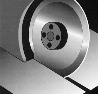

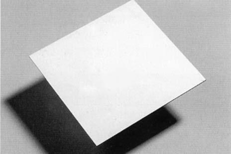
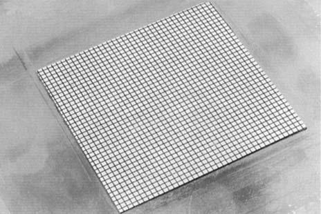
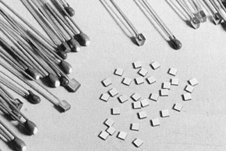
21 NTC Thermistors Manufacturing Process NJ 28 NI 24 NK 20 20
 NV: epoxy")

22 NTC Disc Thermistors ND 03/06/09 NE 03/06/09 NV 06/09 APPLICATIONS Commodity Product: 2 families ND or NE : general purpose NV : professional Alarm and temperature measurement application Temperature regulation application Level detection application Compensation application TECHNOLOGY ND: epoxy-phenolic resin coating NE: epoxy resin coating (recommended for severe mounting conditions) NV: epoxy varnish coating Leads: Radial copper wire tinned Marking: on package only for ND03 & NE03 ND/NE 06/09:Nominal resistance and tolerance for ±5%, ±10% NV06/09: Nominal resistance and tolerance Delivery Mode: Bulk, reeled or ammopacked Leaded Discs N.03 N.06 N.09 PERFORMANCE CHARACTERISTICS Types General purpose Professional ND03 or NE03 ND06 or NE06 ND09 or NE09 NV06 NV09 Climatic category 55/125/ /125/ Operating Temperature 55 to +150 C 55 to +150 C 55 to +150 C 55 to +150 C 55 to +150 C Tolerance on Rn 330Ω to 1MΩ : ± ±5%, ±10%, ±20% ±5%, ±10%, ±20% ±2%, ±5%, ±10% ±2%, ±5%, ±10% (25 C) 5, 10, 20% 1500Ω to 150 kω : ± 3% Maximum dissipation at 25 C 0.25 W 0.71 W 0.9 W 0.69 W 0.85 W Thermal dissipation factor 5 mw/ C 7.1 mw/ C 9 mw/ C 6.9 mw/ C 8.5 mw/ C Thermal time constant 10 s 22 s 30 s 18 s 30 s Response time < 3s STANDARDIZATION NV range : approved by NFC Type: TN115 A for NV06 TN116 for NV09 List: GAM-T1 List: LNZ OPTIONS Consult factory for availability of options: other nominal resistance values other tolerances alternative lead materials or lengths controlled dimensions 21
23 NTC Disc Thermistors ND/NE 03 TABLE OF VALUES ND03/NE03 TYPE ND03/NE (.138) max 3 (.118) max 35 (1.38) min 3 (.118) max ø 0.5 (.020) +10% (0.1) Part Number Rn at 25 C (Ω) Material Code B (K) (1) ± 5% ( B/B (2) ± 3% ) at 25 C (%/ C) N_03I N_03I I 3250 (1) 3.7 N_03J N_03J ,000 J 3480 (2) 3.9 N_03K ,500 N_03K ,200 K 3630 (2) 4.0 N_03L ,700 L 3790 (2) 4.2 N_03L ,300 N_03M ,700 N_03M ,800 M 3950 (2) 4.4 N_03N ,000 N_03N ,000 N 4080 (2) 4.6 N_03P ,000 N_03P ,000 P 4220 (2) 4.7 N_03Q ,000 N_03Q ,000 Q 4300 (2) 4.7 N_03R ,000 N_03R ,000 R 4400 (2) 4.8 N_03S ,000 S 4520 (2) 5.0 N_03T ,000 N_03T ,000 T 4630 (2) 5.1 N_03U ,000,000 U 4840 (2)
24 NTC Disc Thermistors ND/NE/NV 06 TABLE OF VALUES ND06/NE06/NV06 ND06/NE (.248) max 4 (.157) max NV (.248) max 3.5 (.138) max 35 (1.38) min 3 (.118) max ø 0.6 (.024) +10% (1.38) min 3 (.118) max ø 0.6 (.024) +10% (0.2) 5.08 (0.2) Part Number Rn at 25 C (Ω) Material Code N_06J N_06J N_06K N_06K N_06L N_06L ,000 B (K) (1) ± 5% ( B/B (2) ± 3% ) at 25 C (%/ C) J 3480 (2) 3.9 K 3630 (2) 4.0 L 3790 (2) 4.2 N_06M ,500 M 3950 (2) 4.4 N_06N ,200 N_06N ,300 N 4080 (2) 4.6 N_06P ,700 N_06P ,800 P 4220 (2) 4.7 N_06P ,000 N_06Q ,000 N_06Q ,000 Q 4300 (2) 4.7 N_06R ,000 R 4400 (2) 4.8 N_06S ,000 N_06S ,000 S 4520 (2) 5.0 N_06T ,000 T 4630 (2) 5.1 N_06U ,000 N_06U ,000 U 4840 (2) 5.3 N_06U ,000 For other resistance values, please consult us. 23
25 NTC Disc Thermistors ND/NE/NV 09 TABLE OF VALUES ND09/NE09/NV09 ND09/NE (.375) max 5 (.197) max NV (.374) max 3.5 (.138) max 35 (.138) min 3 (.118) max ø 0.6 (.024) +10% (.138) min 3 (.118) max ø 0.6 (.024) +10% (.02) 5.08 (.02) Part Number Rn at 25 C (Ω) Material Code N_09J N_09J N_09K N_09K B (K) (1) ± 5% ( B/B (2) ± 3% ) at 25 C (%/ C) J 3480 (2) 3.9 K 3630 (2) 4.0 N_09L L 3790 (2) 4.2 N_09M N_09M M 3950 (2) 4.4 N_09N ,000 N_09N ,500 N 4080 (2) 4.6 N_09P ,200 N_09P ,300 P 4220 (2) 4.7 N_09Q ,700 N_09Q ,800 Q 4300 (2) 4.7 N_09R ,000 N_09R ,000 R 4400 (2) 4.8 N_09S ,000 S 4520 (2) 5.0 N_09T ,000 N_09T ,000 T 4630 (2) 5.1 N_09U ,000 N_09U ,000 U 4840 (2) 5.3 N_09U ,000 24
26 NTC Disc Thermistors Packaging for Automatic Insertion PACKAGING AND KINK SUFFIXES Tables below indicate the suffixes to specify when ordering to get the required kink and packaging. For devices on tape, it is necessary to specify the height (H or Ho) which is the distance between the tape axis (sprocket holes axis) and the seating plane on the printed circuit board. The following types can be ordered on tape either in AMMOPACK (fan folder) or on REEL in accordance with IEC Straight leads: H represents the distance between the sprocket holes axis and the bottom plane of component body (base of resin or base of stand off). Kinked leads and flat leads: Ho represents the distance between the sprocket holes axis and the base on the knee (kinked leads) or the bottom of the flat part (flat leads). Reel & Ammopack millimeters (inches) Types Suffix H or Ho Leads Quantity/Size Packaging ND/NE 16 ± CA (0.630 ± 0.020) Straight 3000 AMMOPACK & 16 ± 0.5 NJ28 CB (0.630 ± 0.020) Straight 3000 REEL CC 19.5 ± 0.5 (0.768 ± 0.020) CD 19.5 ± 0.5 (0.768 ± 0.020) ND/NE/NV 16 ± 0.5 DA 06/09 (0.630 ± 0.020) DB 16 ± 0.5 (0.630 ± 0.020) DC 19.5 ± 0.5 (0.768 ± 0.020) DD 19.5 ± 0.5 (0.768 ± 0.020) DL 16 ± 0.5 (0.630 ± 0.020) DM 16 ± 0.5) (0.630 ± 0.020) DN 19.5 ± 0.5 (0.768 ± 0.020) DP 19.5 ± 0.5 (0.768 ± 0.020) Bulk Type Quantity/box ND/NE ND/NE ND/NE NV NV NI24 NJ NK20 HOW TO ORDER Straight 3000 AMMOPACK Straight 3000 REEL Straight 1500 AMMOPACK Straight 1500 REEL Straight 1500 AMMOPACK Straight 1500 REEL Kinked 1500 AMMOPACK Kinked 1500 REEL Kinked 1500 AMMOPACK Kinked 1500 REEL NTC Type ND03 NE03 NJ28 NTC Types ND/NE/NV 06/09 H 2.54 (0.10) H Ho 5.08 (0.20) ND06 P K Type Material Code P Resistance 10 kω Tolerance K (±10%) Packaging Bulk 25
27 Automatic Insertion NTC Disc Thermistors TAPING CHARACTERISTICS Missing components A maximum of 3 consecutive components may be missing from the bandolier, surrounded by at least 6 filled positions. The number of missing components may not exceed 0.5% of the total per packing module. The beginning and the end of tape exhibit 8 or 9 blank positions. DIMENSIONS: millimeters (inches) AMMOPACK REEL H 8 (.315) 30 (1.18) Interlayer Paper I L I H 330 (13.0) 46 (1.81) 290 (11.4) L 31 (1.22) 360 (14.2) 42 (1.66) Inside 48(1.99) Outside h h P Reference plane p p Marking on this side H1 W2 P1 A B E H0 W1 W0 W H H1 Adhesive tape I2 D0 P0 d Cross section A - B Direction of unreeling t E Value Tolerance Dimensions Characteristics / -0.5 W Leading tape width 6 ±0.3 W 0 Adhesive tape width / -0.5 W 1 Sprocket hole position 3 max. W2 Distance between the top of the tape and the adhesive 4 ±0.2 D 0 Diameter of sprocket hole 16/19.5 ±0.5 H0 Distance between the tape axis and the seating plane of the component H1 Distance between the tape axis and the top of component body Value Tolerance Dimensions Characteristics 12.7 ±0.2 P 0 Sprocket holes pitch 254 ±1 Distance between 21 consecutive holes 20 pitches 0.7 ±0.2 t Total thickness of tape E Lead spacing ± 0.7 P 1 Distance between the sprocket hole axis and the lead axis 12.7 ±1.0 P Spacing of components ±5% d Lead diameter 0 ±1.3 3 P Verticality of components 0 ±2 3 h Alignment of components 26
28 NTC Leadless Disc Thermistors This type of product is widely used in automotive and consumer applications. They are assembled in custom-probes for sensing the temperature of liquids (water, oil,...), gases or surface of any other component. The metallization covers completely the surfaces of the thermistor. The particularly flat and smooth surfaces ensure an excellent electrical and thermal contact under pressure. Types NR Metallization Physical data (dim. in mm) D E Marking Operating temperature On package only / On parts upon request -40 C to +200 C Custom - designed products defined with: Values and tolerances D ± D R 1 ± R 1 /R 1 at T 1 E ± E R 2 ± R 2 /R 2 at T 2,... DESIGN OF THE THERMISTOR Choice of the resistances If the application is to measure the temperature around a defined point, a unique nominal resistance can be chosen (for example, among standard values of the ND range products presented on pages 20 to 24). When it is required to measure the temperature over selected ranges T 1 T 2, T 2 T 3,..., the corresponding resistance R 1, R 2, R 3,..., must be such that they can be located on the R (T) characteristic of an existing NTC material (for example among standard materials whose R (T) are displayed on pages 36 to 40). The resistances must also be compatible with the resistivity of the material and the dimensions of the thermistor. Choice of the tolerances The precision of the temperature measurement determines the calculation of the tolerance on the resistance: R/R = (%/ C). T ( C) For example, the NTC NR , using N5 material (R (T) characteristic displayed on page 38), requires a precision of 1 C over the temperature range 110 C C. The tolerances can be calculated: R 110 C /R 110 C = 1 C* 2.91%/ C = 2.91% R 120 C /R 120 C = 1 C* 2.76%/ C = 2.76% *For your specific requirements, please consult us. HOW TO ORDER NR Type P/N Code 27
29 NTC Leadless Disc Thermistors We present below some examples of our custom - designed products as an illustration of the different ways to define products. DIMENSIONS: millimeters (inches) Material B R Types D E 1 ± R 1 T 1 R 2 ± R 2 T 2 R 3 ± R 3 T 3 Code (k) at T 1 ( C) at T 2 ( C) at T 3 ( C) NR (.217) ± 0.5 (.020) 1.1 (.043) ± 0.4 (.016) N Ω ± 7.5% Ω ± 5% 96.5 NR (.264) ± 0.5 (.020) 1.7 (.067) ± 0.3 (.012) N Ω ± 3.3% Ω ± 5.3% 140 NR (.217) ± 0.5 (.020) 1.0 (.040) ± 0.2 (.008) N Ω ± 2.9% Ω ± 2.8% 120 NR (.217) ± 0.5 (.020) 1.3 (.051) ± 0.4 (.016) S Ω± 7.5% Ω ± 5% 90 NR (.193) ± 0.3 (.012) 1.5 (.060) ± 0.4 (.016) M Ω ± 10% Ω ± 5% NR (.217) ± 0.4 (.016) 1.0 (.040) ± 0.2 (.008) P Ω ± 10% 25 NR (.275) ± 0.3 (.012) 1.2 (.047) ± 0.2 (.008) L Ω ± 10% Ω ± 7.5% Ω ± 6.7% 100 NR (.014) ± 0.3 (.012) 1.7 (.067) ± 0.3 (.012) K Ω ± 6% Ω ± 5.4% 96.5 NR (.217) ± 0.5 (.020) 1.5 (.060) ± 0.4 (.016) J Ω ±5% 25 NR (.217) ± 0.5 (.020) 1.0 (.040) ± 0.2 (.008) P Ω ± 10% Ω ± 7% Ω ± 7% 120 NR (.185) ± 0.4 (.016) 1.2 (.047) ± 0.2 (.008) R Ω ±2% 25 NR (.193) ± 0.3 (.012) 1.2 (.047) ± 0.2 (.008) N Ω ± 10% Ω ± 6.7% Ω ± 5% 105 NR (.181) ± 0.3 (.012) 1.4 (.055) ± 0.3 (.012) J Ω ± 13% Ω ± 10% 100 NR (.228) ± 0.3 (.012) 1.0 (.040) ± 0.2 (.008) L Ω ± 8.7% Ω ± 10% Ω ± 7.8% 100 NR (.240) ± 0.3 (.012) 1.5 (.060) ± 0.3 (.012) N Ω ± 9.2% Ω ± 8.5% Ω ± 8.5% 130 NR (.264) ± 0.4 (.016) 1.7 (.067) ± 0.3 (.012) N Ω ± 11% Ω ± 7% 100 NR (.197) ± 0.5 (.020) 1.5 (.060) ± 0.5 (.020) J Ω ± 10% Ω ± 7% 121 NR (.236) ± 0.5 (.020) 3.2 (.125) ± 0.3 (.012) P Ω ± 3% Ω ± 3% 96.5 NR (.217) ± 0.5 (.020) 1.1 (.043) ± 0.4 (.016) Q Ω ± 9% Ω ± 7.7% 96.5 Resistance - Temperature characteristics: pages 36 to
NTC Disc Thermistors ND 03/06/09 NE 03/06/09 NV 06/09 APPLICATIONS TECHNOLOGY PERFORMANCE CHARACTERISTICS OPTIONS STANDARDIZATION
 ND 03/06/09 NE 03/06/09 NV 06/09 APPLICATIONS Commodity Product: 2 families ND or NE : general purpose NV : professional Alarm and temperature measurement application Temperature regulation application
0.5 (.020) (.051) 0.2 (.008) min 0.2 (.008) min
 (.051) 0.2 (.008) min 0.2 (.008) min") With Nickel Barrier Termination NB 12 - NB 20 Chip thermistors are high quality and low cost devices especially developed for surface mounting applications. They are widely used for temperature compensation
With Nickel Barrier Termination NB 12 - NB 20 Chip thermistors are high quality and low cost devices especially developed for surface mounting applications. They are widely used for temperature compensation
Zinc Oxide Varistors. VE/VF Types for Heavy Duty Applications ( P Series ) FEATURES PARTICULAR CHARACTERISTICS 18 TPC
 FEATURES PARTICULAR CHARACTERISTICS 18 TPC") VE/VF Types for Heavy Duty Applications ( P Series ) FEATURES P Series are especially dedicated to heavy duty applications encountered in the AC power network. Higher surge current and energy ratings provide
VE/VF Types for Heavy Duty Applications ( P Series ) FEATURES P Series are especially dedicated to heavy duty applications encountered in the AC power network. Higher surge current and energy ratings provide
Varistors to
 FEATURES Zinc oxide disc, epoxy coated Straight leads Straight leads with flange (2322 592 and 593 series only) Kinked leads. APPLICATION Suppression of transients. DESCRIPTION The varistors consist of
WW12C, WW08C, WW06C, WW04C, WW02C. Low ohm chip resistors ( power ) Size 1206, 0805, 0603, 0402, 0201
 Size 1206, 0805, 0603, 0402, 0201") WW12C, WW08C, WW06C, WW04C, WW02C ±5%, ±1%, ±0.5% Low ohm chip resistors ( power ) Size 1206, 0805, 0603, 0402, 0201 *Contents in this sheet are subject to change without prior notice. Page 1 of 8 ASC_WWxxC_V05
WW12C, WW08C, WW06C, WW04C, WW02C ±5%, ±1%, ±0.5% Low ohm chip resistors ( power ) Size 1206, 0805, 0603, 0402, 0201 *Contents in this sheet are subject to change without prior notice. Page 1 of 8 ASC_WWxxC_V05
Resin-Molded, Radial-Lead Solid Tantalum Capacitors
 Resin-Molded, Radial-Lead Solid Tantalum Capacitors PERFORMANCE CHARACTERISTICS Operating Temperature: - 55 C to +25 C (above 85 C, voltage derating is required) Capacitance Range: 0. μf to 3 μf Capacitance
Lead (Pb)-free Thick Film, Rectangular Commodity Chip Resistors
-free Thick Film, Rectangular Commodity Chip Resistors") ...BC e3 Lead (Pb)-free Thick Film, Rectangular Commodity Chip Resistors STANDARD ELECTRICAL SPECIFICATIONS TYPE CASE SIZE IMPERIAL CASE SIZE METRIC POWER RATING P 70 W LIMITING ELEMENT VOLTAGE U max.
...BC e3 Lead (Pb)-free Thick Film, Rectangular Commodity Chip Resistors STANDARD ELECTRICAL SPECIFICATIONS TYPE CASE SIZE IMPERIAL CASE SIZE METRIC POWER RATING P 70 W LIMITING ELEMENT VOLTAGE U max.
CHIP RESISTOR. Chip Resistors Selection Guide. General Purpose Chip Resistor. Zero Ohm Jumper Resistor. Chip Resistor Array MAX WORKING VOLTAGE
 Chip Resistors Selection Guide General Purpose Chip Resistor SIZE/ mm POWER RATING MAX WORKING VOLTAGE TOLERANCE RESISTANCE RANGE 0402 1.00*0.50 0603 1.60*0.80 1/10W 0. 0805 2.00*1.25 1/8W 1 0. 1206 3.10*1.60
Resin-Molded, Radial-Lead Solid Tantalum Capacitors
 Resin-Molded, Radial-Lead Solid Tantalum Capacitors PERFORMANCE CHARACTERISTICS Operating Temperature: -55 C to +25 C (above 85 C, voltage derating is required) Capacitance Range: 0. μf to 3 μf Capacitance
WK25V, WK20V, WK12V, WK08V, WK06V. Thick Film High Voltage Chip Resistors. Size 2512, 2010,1206, 0805, 0603
 WK25V, WK20V, WK12V, WK08V, WK06V ±5%, ±2%, ±1%, ±0.5% Thick Film High Voltage Chip Resistors Size 2512, 2010,1206, 0805, 0603 *Contents in this sheet are subject to change without prior notice. Page 1
HIGH VOLTAGE MULTILAYER CERAMIC CAPACITORS
 DESCRIPTION: RoHS compliant (*) Capacitors 0805 to 6560 Rated voltage 1000V to 10KV Dielectric Type I and II SMD and leaded versions * Non RoHS version still maintained for current applications. I. Foreword
Ceramic Disc Capacitors Class 1 and 2, 500 V DC, General Purpose
 D Series Ceramic Disc Capacitors D D FEATURES Low losses High stability Tangent line SH Tangent line SH High capacitance in small size Kinked (preferred) or straight leads Compliant to RoHS directive 2002/95/EC
NPN/PNP low V CEsat Breakthrough in Small Signal (BISS) transistor pair in a SOT457 (SC-74) Surface Mounted Device (SMD) plastic package.
 transistor pair in a SOT457 (SC-74) Surface Mounted Device (SMD) plastic package.") Rev. 02 14 July 2005 Product data sheet 1. Product profile 1.1 General description NPN/PNP low V CEsat Breakthrough in Small Signal (BISS) transistor pair in a SOT457 (SC-74) Surface Mounted Device (SMD)
Rev. 02 14 July 2005 Product data sheet 1. Product profile 1.1 General description NPN/PNP low V CEsat Breakthrough in Small Signal (BISS) transistor pair in a SOT457 (SC-74) Surface Mounted Device (SMD)
Metallized polyester film capacitors MKT 470
 MKT RADIAL POTTED TYPE PITCH 5 mm CBA141 Fig.1 Simplified outlines. FEATURES Low-inductive wound cell of metallized (PETP) film Potted with epoxy resin in a flame-retardant case Radial leads of solder-coated
T h e rm i s t o r s
 Data Pack E Issued March 00 - T h e rm i s t o r s NTC thermistors The R S range of NTC thermistors includes standard tolerance negative temperature coefficient thermistors, a range of small close tolerance
NTC Thermistors, Accuracy Line
 N Thermistors, Accuracy Line FEATURES Accuracy over a wide temperature range High stability over a long life Excellent price/performance ratio APPLICATIONS Temperature sensing and control QUICK REFERENCE
Lead (Pb)-Free Thick Film, Rectangular High Value Chip Resistor
-Free Thick Film, Rectangular High Value Chip Resistor") Lead (Pb)-Free Thick Film, Rectangular High Value Chip Resistor FEATURES High resistance values (up to 470M) Suitable for voltage dividers and hybrids Pure tin plating provides compatibility with lead
Lead (Pb)-Free Thick Film, Rectangular High Value Chip Resistor FEATURES High resistance values (up to 470M) Suitable for voltage dividers and hybrids Pure tin plating provides compatibility with lead
NPN/PNP transistor pair connected as push-pull driver in a SOT457 (SC-74) Surface-Mounted Device (SMD) plastic package.
 Surface-Mounted Device (SMD) plastic package.") Rev. 0 26 September 2006 Product data sheet. Product profile. General description NPN/PNP transistor pair connected as push-pull driver in a SOT457 (SC-74) Surface-Mounted Device (SMD) plastic package..2
Rev. 0 26 September 2006 Product data sheet. Product profile. General description NPN/PNP transistor pair connected as push-pull driver in a SOT457 (SC-74) Surface-Mounted Device (SMD) plastic package..2
NPN/PNP low V CEsat Breakthrough in Small Signal (BISS) transistor pair in a SOT457 (SC-74) Surface Mounted Device (SMD) plastic package.
 transistor pair in a SOT457 (SC-74) Surface Mounted Device (SMD) plastic package.") Rev. 03 11 December 2009 Product data sheet 1. Product profile 1.1 General description NPN/PNP low V CEsat Breakthrough in Small Signal (BISS) transistor pair in a SOT457 (SC-74) Surface Mounted Device
Rev. 03 11 December 2009 Product data sheet 1. Product profile 1.1 General description NPN/PNP low V CEsat Breakthrough in Small Signal (BISS) transistor pair in a SOT457 (SC-74) Surface Mounted Device
Multilayer Ceramic Chip Capacitors
 HIGH VOLTAGE SERIES JARO high voltage series Multilayer Ceramic Capacitors are constructed by depositing alternative layers of ceramic dielectric materials and internal metallic electrodes, by using advanced
High Precision Thick Film chip resistors. Size 1206, 0805, 0603, 0402, 0201
 WK2K, WK08K, WK06K, WK04K, WK02K ±.0%, ±0.5% Thick Film TC50/TC00 High Precision Thick Film chip resistors Size 206, 0805, 0603, 0402, 020 Page of 7 ASC_WKxxK_V07 NOV- 205 FEATURE. SMD Thick film resistor
AC Line Rated Ceramic Disc Capacitors Class X1, 760 V AC, Class Y1, 500 V AC
 AC Line Rated Ceramic Disc Capacitors Class X1, 760 V AC, Class Y1, 500 V AC FEATURES Complying with IEC 60384-14 4 th edition Can pass 10 kv pulses (10 per polarity) Withstands 85 / 85 / 1000 h test Reduced
Lead (Pb)-Free Thick Film, Rectangular, Trimmable Chip Resistors
-Free Thick Film, Rectangular, Trimmable Chip Resistors") Lead (Pb)-Free Thick Film, Rectangular, Trimmable Chip Resistors STANDARD ELECTRICAL SPECIFICATIONS MODEL CASE SIZE INCH CASE SIZE METRIC POWER RATING P 70 W LIMITING ELEMENT VOLTAGE Umax. AC RMS /DC V
Lead (Pb)-Free Thick Film, Rectangular, Trimmable Chip Resistors STANDARD ELECTRICAL SPECIFICATIONS MODEL CASE SIZE INCH CASE SIZE METRIC POWER RATING P 70 W LIMITING ELEMENT VOLTAGE Umax. AC RMS /DC V
Lead (Pb)-Bearing Thick Film, Rectangular High Value Chip Resistor
-Bearing Thick Film, Rectangular High Value Chip Resistor") Lead (Pb)-Bearing Thick Film, Rectangular High Value Chip Resistor FEATURES High resistance values (up to 470M) Suitable for voltage dividers and hybrids Lead (Pb)-bearing termination plating on Ni barrier
Lead (Pb)-Bearing Thick Film, Rectangular High Value Chip Resistor FEATURES High resistance values (up to 470M) Suitable for voltage dividers and hybrids Lead (Pb)-bearing termination plating on Ni barrier
High Ohmic/High Voltage Resistors
 High Ohmic/High Voltage Resistors A metal glazed film is deposited on a high grade ceramic body. After a helical groove has been cut in the resistive layer, tinned electrolytic copper wires are welded
NTC Thermistors, Accuracy Line
 FEATURES Accuracy over a wide temperature range High stability over a long life Excellent price/performance ratio Old part number was 2322 640 3/4/6... Component in accordance to RoHS 2002/95/EC and WEEE
Ceramic Disc Capacitors Class 1, 3 kv DC
 S Series Ceramic Disc Capacitors D D FEATURES Low losses High stability Tangent line SH Tangent line SH High capacitance in small size Kinked (preferred) or straight leads Compliant to RoHS directive 2002/095/EC
Axial Leaded Multilayer Ceramic Capacitors for Automotive Applications Class 1 and Class 2, 50 V DC, 100 V DC, 200 V DC
 Axial Leaded Multilayer Ceramic Capacitors for Automotive Applications Class 1 and Class 2, 50 V DC, 100 V DC, 200 V DC FEATURES AEC-Q200 qualified with PPAP available High reliability MLCC insert with
Data sheet FIXED THICK FILM CHIP RESISTORS; RECTANGULAR TYPE RMC1/32,1/20,1/16S,1/16,1/10,1/8,1/4,1/2,1. AEC-Q200 qualified (Without RMC1/32)
") No.: RMC-K-HTS-0006 /11 Date: 2017. 4. 18 Data sheet Title: Style: RMC1/32,1/20,1/16S,1/16,1/10,1/8,1/4,1/2,1 AEC-Q200 qualified (Without RMC1/32) RoHS COMPLIANCE ITEM Halogen and Antimony Free Note: Stock
No.: RMC-K-HTS-0006 /11 Date: 2017. 4. 18 Data sheet Title: Style: RMC1/32,1/20,1/16S,1/16,1/10,1/8,1/4,1/2,1 AEC-Q200 qualified (Without RMC1/32) RoHS COMPLIANCE ITEM Halogen and Antimony Free Note: Stock
150 V, 2 A NPN high-voltage low V CEsat (BISS) transistor
 transistor") Rev. 0 November 2009 Product data sheet. Product profile. General description NPN high-voltage low V CEsat Breakthrough In Small Signal (BISS) transistor in a medium power SOT223 (SC-73) Surface-Mounted
Rev. 0 November 2009 Product data sheet. Product profile. General description NPN high-voltage low V CEsat Breakthrough In Small Signal (BISS) transistor in a medium power SOT223 (SC-73) Surface-Mounted
DATA SHEET. Radial series Leaded ceramic multilayer capacitors. BCE Sud Passive Components Oct 16
 DATA SEET File under BCE Sud Passive Components, 2003 Oct 16 BCE Sud Passive Components A former part of Philips Components FEATURES Very high capacitance per unit volume Low cost. APPLICATIONS These conformally
Class 1, 100 V (DC) (flanged types) Miniature ceramic plate capacitors
 (flanged types) Miniature ceramic plate capacitors") FEATURES High-frequency circuits Temperature compensating High stability Space saving. APPLICATIONS In a great variety of electronic circuits, e.g. in filters and tuning circuits where high stability and/or
FEATURES High-frequency circuits Temperature compensating High stability Space saving. APPLICATIONS In a great variety of electronic circuits, e.g. in filters and tuning circuits where high stability and/or
Data sheet FIXED CHIP RESISTORS; RECTANGULAR TYPE & WIDE TERMINATION. AEC-Q200 qualified. RoHS COMPLIANCE ITEM Halogen and Antimony Free
 No.: TWMC K HTS-0001 /4 Date: 2017. 4. 21 Data sheet Title: FIXED CHIP RESISTORS; RECTANGULAR TYPE & WIDE TERMINATION Style: TWMC32, 50, 63 AEC-Q200 qualified RoHS COMPLIANCE ITEM Halogen and Antimony
Double-Sided Chip Resistors
 Double-Sided Two parallel resistance elements in a single chip Excellent pulse withstand performance Laser trimmed up to 0.5% tolerance Enhanced working voltage Enhanced power rating Pb-free terminations
Platinum SMD Flat Chip Temperature Sensor
 Platinum SMD Flat Chip Temperature Sensor FEATURES Standardized characteristics according to IEC 60751 Advanced thin film technology Short reaction times down to t 0.9 2 s (in air) Outstanding stability
AC Line Rated Ceramic Disc Capacitors Class X1, 760 V AC, Class Y1, 500 V AC
 AC Line Rated Ceramic Disc Capacitors Class X1, 760 V AC, Class Y1, 500 V AC FEATURES Complying with IEC 60384-14 4 th edition High reliability Vertical (inline) kinked or straight leads Singlelayer AC
Commercial Chip - C0G 16Vdc to 10kVdc
 Commercial Chip - CG 16Vdc to 1kVdc A range of commercial MLC chip capacitors in Ultra stable EIA Class I CG, or NP, dielectric. CG chips are used in precision circuitry requiring Class I stability and
Ceramic Disc DC Capacitors Class 2, Low Loss 500 V, 1 kv, 2 kv and 3 kv
 Ceramic Disc DC Capacitors Class 2, tangent line D SH FEATURES High reliability Low losses High capacitance in small size Kinked leads Compliant to RoHS directive 2002/95/EC F Capacitors with inside kink
Data sheet FIXED THICK FILM CHIP RESISTORS; RECTANGULAR TYPE AND HIGH POWER ANTI SURGE. AEC-Q200 qualified
 No.: RPCH-K-HTS-0001 /2 Date: 2017.4.21 Data sheet Title: Style: FIXED THICK FILM CHIP RESISTORS; RECTANGULAR TYPE AND HIGH POWER ANTI SURGE RPCH16,20,32,35 AEC-Q200 qualified RoHS COMPLIANCE ITEM Halogen
Technical Data Sheet. Pb Free. Specification GR101 SSC. Customer. Rev. 02 January 서식번호 : SSC- QP (Rev.0.
 Specification GR101 Pb Free Drawn SSC Approval Customer Approval [ Contents ] 1. Description 2. Absolute maximum ratings 3. Electro-Optical characteristics 4. Characteristic diagrams 5. Reliability result
NTC Thermistor:TSM Series
 Features. RoHS & Halogen Free (HF) compliant. EIA size: 00, 00, 00, 080. Highly reliable structure. Operating temperature range: -0 ~+. Wide resistance range. Cost effective. Agency recognition: UL / cul
Disc Ceramic Capacitors
 Professional Ceramic Capacitors - Class I, II and III I-STD-202F The professional ceramic disc capacitors were specially developed for applications in severe environmental conditions, high humidity, temperature,
Metallized Polyester PCMT 365/366/367 film capacitors
 Metallized Polyester PCMT 365/366/367 MKT RADIAL LACQUERED CAPACITORS (Dipped Type) - Orange Pitch 5.0/7.5mm 365 366 367 QUICK REFERENCE DATA acitance range (E12 series) 0.001 to 1.0 acitance tolerance
Precision Thin Film Chip Resistor Array
 ACAC 0612 (concave terminations) and ACAS 0612 (convex terminations) thin chip resistor arrays combine the proven reliability of precision thin film chip resistor products with the advantages of chip resistor
Lead (Pb)-free Thick Film, Rectangular Commodity Chip Resistors
-free Thick Film, Rectangular Commodity Chip Resistors") Lead (Pb)-free Thick Film, Rectangular Commodity Chip Resistors FEATURES High volume product suitable for commercial applications Stability ( R/R 1 % for 1000 h at 70 C) Lead (Pb)-free solder contacts
Lead (Pb)-free Thick Film, Rectangular Commodity Chip Resistors FEATURES High volume product suitable for commercial applications Stability ( R/R 1 % for 1000 h at 70 C) Lead (Pb)-free solder contacts
FEATURES APPLICATIONS DESCRIPTION QUICK REFERENCE DATA. PILKOR components
 FEATURES Excellent anti-surge characteristics Stable characteristics to moisture resistance even in high resistance range. Good replacement for ceramic plate resistors. APPLICATIONS Telecommunication Industrial
NTC Thermistors [From Philips Data Handbook PA ]
![NTC Thermistors [From Philips Data Handbook PA ]](/thumbs/72/67578653.jpg "NTC Thermistors [From Philips Data Handbook PA ]") NTC Thermistors [From Philips Data Handbook PA02 1989] Definition and composition Negative temperature coefficient thermistors (NTCs) are resistive components, of which the resistance decreases as temperature
NTC Thermistors [From Philips Data Handbook PA02 1989] Definition and composition Negative temperature coefficient thermistors (NTCs) are resistive components, of which the resistance decreases as temperature
Precision Leaded Resistors
 FEATURES Approved according to CECC 40101-806 Advanced thin film technology Low TC: ± 15 to Precision tolerance of value: ± 0.1 % and ± 0.25 % Superior overall : class 0.05 Wide precision range: 10 to
Commercial Chip - R3L 16Vdc to 5kVdc
 Commercial Chip - R3L 16Vdc to 5kVdc A range of commercial MLC chip capacitors in R3L dielectric. This is a Class I temperature compensating N22 dielectric with an energy density that exceeds conventional
WW12E, WW08E, WW06E ±5%, ±1% Thick film low ohm chip resistors Size 1206, 0805, 0603 RoHS Exemption free and Halogen free
 WW12E, WW08E, WW06E ±5%, ±1% Thick film low ohm chip resistors Size 1206, 0805, 0603 RoHS Exemption free and Halogen free *Contents in this sheet are subject to change without prior notice. Page 1 of 7
Radial Leaded Multilayer Ceramic Capacitors For Automotive Applications Class 1 and Class 2, 50 V DC, 100 V DC, 200 V DC
 Radial eaded Multilayer Ceramic Capacitors For Automotive Applications Class 1 and Class 2, 50 V DC, 100 V DC, 200 V DC FEATURES AEC-Q200 qualified with PPAP available igh reliability MCC insert with wet
Ceramic Disc Capacitors Class 1 and 2, 100 V DC, General Purpose
 D Series Ceramic Disc Capacitors D D EATURES Low losses High stability Tangent line SH Tangent line DR High capacitance in small size Kinked (preferred) or straight leads Compliant to RoHS directive 2002/95/EC
Tantalum Through-Hole Capacitors Molded Radial T370 & T378 Micron MIL-PRF-49137/6 (CX06 Style) Applications
 Applications") Overview The KEMET T370 and T378 Micron MIL-PRF-49137/6 (CX06 Style) capacitors are available in a variety of case styles and sizes. These capacitors are designed to operate from 55 C to +85 C at full
Overview The KEMET T370 and T378 Micron MIL-PRF-49137/6 (CX06 Style) capacitors are available in a variety of case styles and sizes. These capacitors are designed to operate from 55 C to +85 C at full
DATA SHEET SURFACE-MOUNT CERAMIC MULTILAYER CAPACITORS General purpose & High capacitance Class 2, X5R
 DATA SHEET SURFACE-MOUNT CERAMIC MULTILAYER CAPACITORS General purpose & High capacitance Class 2, 6.3 V TO 50 V 10 nf to 100 µf RoHS compliant Product Specification Product specification 2 Surface-Mount
Approval sheet WF10A. 1%, 5% Ultra High Power Chip Resistors Size 1210, 3/4W. *Contents in this sheet are subject to change without prior notice.
 WF10A 1%, 5% Ultra High Power Chip Resistors Size 1210, 3/4W *Contents in this sheet are subject to change without prior notice. Page 1 of 7 ASC_WF10A_V02 MAY - 2016 FEATURE 1. High reliability and stability
Non Magnetic Chip C0G & X7R
 Non Magnetic Chip CG & X7R This range of MLC chip capacitors that are completely non magnetic. They are designed to operate in non magnetic environments such as Magnetic Resonance Imaging (MRI) and Nuclear
Data sheet FIXED THICK FILM CHIP RESISTORS; RECTANGULAR TYPE ANDULTRAHIGH VOLTAGE. AEC-Q200 qualified. RoHS COMPLIANCE ITEM Halogen and Antimony Free
 No.: RZC K HTS 0001 /6 Date: 2017. 4. 21 Data sheet Title: FIXED THICK FILM CHIP RESISTORS; RECTANGULAR TYPE ANDULTRAHIGH VOLTAGE Style: RZC50, 63 AEC-Q200 qualified RoHS COMPLIANCE ITEM Halogen and Antimony
WW25R ±1%, ±5%, 2W Metal plate low ohm power chip resistors Size 2512 (6432)
") WW25R ±1%, ±5%, 2W Metal plate low ohm power chip resistors Size 2512 (6432) Current Sensing Type Automotive AEC Q200 compliant *Contents in this sheet are subject to change without prior notice. Page
WW25R ±1%, ±5%, 2W Metal plate low ohm power chip resistors Size 2512 (6432) Current Sensing Type Automotive AEC Q200 compliant *Contents in this sheet are subject to change without prior notice. Page
ATC 700 B Series NPO Porcelain and Ceramic Multilayer Capacitors
 ATC 700 Series NPO Porcelain and Ceramic Multilayer Capacitors Case Size Capacitance Range (.1" x.1") 0.1 pf to 5 pf Low ESR/ESL Zero TCC Low Noise High Self-Resonance Rugged Construction Established Reliability
WW25Q ±1%, ±5%, 1W Metal plate low ohm power chip resistors Size 2512 (6432)
") WW25Q ±1%, ±5%, 1W Metal plate low ohm power chip resistors Size 2512 (6432) Current Sensing Type Automotive AEC Q200 compliant *Contents in this sheet are subject to change without prior notice. Page
WW25Q ±1%, ±5%, 1W Metal plate low ohm power chip resistors Size 2512 (6432) Current Sensing Type Automotive AEC Q200 compliant *Contents in this sheet are subject to change without prior notice. Page
High Operating Temperature Radial Leaded Multilayer Ceramic Capacitors for Automotive Applications, 50 V DC, 100 V DC, 200 V DC
 High Operating Temperature Radial eaded Multilayer Ceramic Capacitors for Automotive Applications, 5 V DC, 1 V DC, 2 V DC FEATURES AEC-Q2 qualified with PPAP available High reliability MCC insert with
DATA SHEET SURFACE-MOUNT CERAMIC MULTILAYER CAPACITORS General purpose & High capacitance Class 2, X5R
 DATA SHEET SURFACE-MOUNT CERAMIC MULTILAYER CAPACITORS General purpose & High capacitance Class 2, 6.3 V TO 50 V 10 nf to 100 µf RoHS compliant Product Specification Product specification 2 Surface-Mount
DATA SHEET SURFACE MOUNT MULTILAYER CERAMIC CAPACITORS General purpose & High capacitance Class 2, X5R
 Product Specification DATA SHEET SURFACE MOUNT MULTILAYER CERAMIC CAPACITORS General purpose & High capacitance Class 2, 4 V TO 50 V 100 pf to 220 µf RoHS compliant & Halogen free Product specification
ATC 200 A Series BX Ceramic Multilayer Capacitors
 200 A Series BX Ceramic Multilayer Capacitors Case A Size Capacitance Range (.055" x.055") 5 pf to 0.01 µf Low ESR/ESL Mid-K Rugged High Reliability Construction Extended VDC Available, the industry leader,
High-ohmic/high-voltage resistors
 FEATURES These resistors meet the safety requirements of: UL1676 (range 510 kω to 11 MΩ) EN60065 BS60065 (U.K.) NFC 92-130 (France) VDE 0860 (Germany) High pulse loading capability Small size. APPLICATIONS
TYPE. max. working voltage 250 V 350 V 500 V 750 V. max. overload voltage 500 V 700 V 1000 V 1500 V. basic specifications IEC B
 FEATURES Non inductive High pulse loading capability. APPLICATIONS Application for overload and high voltage surge hazard circuits. DESCRIPTION A carbon film is deposited on a high grade ceramic body.
DATA SHEET SURFACE-MOUNT CERAMIC MULTILAYER CAPACITORS General purpose & High capacitance Class 2, Y5V
 Product Specification January 12, 2016 V.6 DATA SHEET SURFACE-MOUNT CERAMIC MULTILAYER CAPACITORS General purpose & High capacitance Class 2, 6.3 V TO 50 V 10 nf to 47 µf RoHS compliant & Halogen Free
Applications. Capacitance Code (pf) First two digits represent significant figures. Third digit specifies number of zeros.
 First two digits represent significant figures. Third digit specifies number of zeros.") AC Line EMI Suppression and RC Networks P410 Series, Integrated Resistor, Metallized Impregnated Paper, Class X1, 300 VAC Overview Applications The P410 Series is constructed of multilayer metallized paper
AC Line EMI Suppression and RC Networks P410 Series, Integrated Resistor, Metallized Impregnated Paper, Class X1, 300 VAC Overview Applications The P410 Series is constructed of multilayer metallized paper
WF12H, WF08H, WF06H, WF04H ±0.5%, ±0.1% Thick film high precision chip resistors Size 1206, 0805, 0603, 0402
 WF12H, WF08H, WF06H, WF04H ±0.5%, ±0.1% Thick film high precision chip resistors Size 1206, 0805, 0603, 0402 *Contents in this sheet are subject to change without prior notice. Page 1 of 6 ASC_WFxxH_V02
1000 to pf (E3 series) Dielectric material K2000 K5000 K14000 Rated DC voltage 100 V 100 V 63 V Tolerance on capacitance ±10% 20/+50% 20/+80%
 Dielectric material K2000 K5000 K14000 Rated DC voltage 100 V 100 V 63 V Tolerance on capacitance ±10% 20/+50% 20/+80%") , Class 2, 63,, V and 1 V (DC) handbook, 4 columns FEATURES General purpose Coupling and decoupling Space saving. APPLICATIONS In electronic circuits where non-linear change of capacitance with temperature
, Class 2, 63,, V and 1 V (DC) handbook, 4 columns FEATURES General purpose Coupling and decoupling Space saving. APPLICATIONS In electronic circuits where non-linear change of capacitance with temperature
Produkt Information. Ultra Low Ohm (Metal Strip) Chip Resistor (LR Series) Scope. Features. Applications. Construction
 Chip Resistor (LR Series) Scope. Features. Applications. Construction") Scope Ultra Low Ohm (Metal Strip) Chip Resistor (LR Series) -This specification applies to all sizes of rectangular-type fixed chip resistors with alloy as mater. Features -High power rating up to 3 Watts
Scope Ultra Low Ohm (Metal Strip) Chip Resistor (LR Series) -This specification applies to all sizes of rectangular-type fixed chip resistors with alloy as mater. Features -High power rating up to 3 Watts
Aluminum Capacitors SMD (Chip) Long Life Vertical
 Long Life Vertical") Aluminum Capacitors SMD (Chip) Long Life Vertical FEATURES Polarized aluminum electrolytic capacitors, non-solid electrolyte, self healing SMD-version with base plate, vertical construction requiring minimum
Aluminum Capacitors SMD (Chip) Long Life Vertical FEATURES Polarized aluminum electrolytic capacitors, non-solid electrolyte, self healing SMD-version with base plate, vertical construction requiring minimum
Aluminum Electrolytic Capacitors SMD (Chip) Long Life Vertical
 Long Life Vertical") Aluminum Electrolytic Capacitors SMD (Chip) Long Life Vertical FEATURES Polarized aluminum electrolytic capacitors, non-solid electrolyte, self healing SMD-version with base plate, vertical construction
Aluminum Electrolytic Capacitors SMD (Chip) Long Life Vertical FEATURES Polarized aluminum electrolytic capacitors, non-solid electrolyte, self healing SMD-version with base plate, vertical construction
5-V Low Drop Fixed Voltage Regulator TLE
 5-V Low Drop Fixed Voltage Regulator TLE 427-2 Features Output voltage tolerance ±2% 65 ma output current capability Low-drop voltage Reset functionality Adjustable reset time Suitable for use in automotive
In data sheets and application notes which still contain NXP or Philips Semiconductors references, use the references to Nexperia, as shown below.
 Important notice Dear Customer, On 7 February 2017 the former NXP Standard Product business became a new company with the tradename Nexperia. Nexperia is an industry leading supplier of Discrete, Logic
DATA SHEET SURFACE MOUNT MULTILAYER CERAMIC CAPACITORS General purpose & High capacitance Class 2, X5R
 DATA SHEET SURFACE MOUNT MULTILAYER CERAMIC CAPACITORS General purpose & High capacitance Class 2, 4 V TO 50 V 100 pf to 100 µf RoHS compliant & Halogen free Product Specification Product specification
In data sheets and application notes which still contain NXP or Philips Semiconductors references, use the references to Nexperia, as shown below.
 Important notice Dear Customer, On 7 February 2017 the former NXP Standard Product business became a new company with the tradename Nexperia. Nexperia is an industry leading supplier of Discrete, Logic
65 V, 100 ma NPN/PNP general-purpose transistor. Table 1. Product overview Type number Package NPN/NPN PNP/PNP Nexperia JEITA
 Rev. 1 17 July 29 Product data sheet 1. Product profile 1.1 General description NPN/PNP general-purpose transistor pair in a very small Surface-Mounted Device (SMD) plastic package. Table 1. Product overview
Interference suppression film capacitors MKP 336 1
 MKP RADIAL POTTED TYPE PITCH /15/22.5/27.5 mm l b h lt P d t CBA196 Fig.1 Simplified outlines. FEATURES to 27.5 mm lead pitch Supplied loose in box and taped on reel Consists of a low-inductive wound cell
Metallized Polyester PCMT 365/366/367 film capacitors
 Metallized Polyester PCMT 365/366/367 MKT RADIAL LACQUERED CAPACITORS (Dipped Type) - Orange Pitch 5.0/7.5mm 365 366 367 QUICK REFERENCE DATA acitance range (E12 series) 0.001 to 1.0μF acitance tolerance,
NTC Thermistors, Radial Leaded, Standard Precision
 FEATURES Accuracy over a wide temperature range High stability over a long life Excellent price/performance ratio UL recognized, file E148885 Old part number was 64 /4/6... Component in accordance to RoHS
single, leadless single single
 Silicon PIN Diode Series diode for mobile communication in low loss transmitreceiver switches Band switch for TVtuners Very low forward resistance (typ..65 Ω @ 5 ma) Low capacitance (typ..5 pf @ V) Fast
Metal Oxide Film Resistors Axial Connections Metal Oxide Film Resistors 1/4W, 5% Components
 Metal Oxide Film Resistors Axial Connections Metal Oxide Film Resistors 1/4W, 5% Components High safety standard, high purity ceramic core Excellent non-flame coating Stable performance in diverse environment,
Multilayer Ceramic Chip Capacitors
 SELECTION OF CERAMIC CHIP CAPACITORS JARO Multilayer Ceramic Chip Capacitors offer the most complete range of characteristics and configurations available in the industry. We suggest your selection of
Specification YGHR411-H
 Specification HR411H Pb Free Drawn SSC Approval Customer Approval [ Contents ] 1. Description 2. Absolute maximum ratings 3. ElectroOptical characteristics 4. Characteristic diagrams 5. Reliability result
Applications. Capacitance Code (pf) First two digits represent significant figures. Third digit specifies number of zeros.
 First two digits represent significant figures. Third digit specifies number of zeros.") AC Line EMI Suppression and RC Networks P409 Series, Integrated Resistor, Metallized Impregnated Paper, Class X2, 275 VAC Overview Applications The P409 Series is constructed of multilayer metallized paper
AC Line EMI Suppression and RC Networks P409 Series, Integrated Resistor, Metallized Impregnated Paper, Class X2, 275 VAC Overview Applications The P409 Series is constructed of multilayer metallized paper
DATA SHEET SURFACE-MOUNT CERAMIC MULTILAYER CAPACITORS C-Array: Class 2, X7R 16/25/50 V size 0612 (4 0603) Product Specification Jul 21, 2003 V.
 Product Specification Jul 21, 2003 V.") DATA SHEET SURFACE-MOUNT CERAMIC MULTILAYER CAPACITORS C-Array: Class 2, X7R 16/25/50 V Product Specification Jul 21, 2003 V.6 FEATURES 0612 (4 0603) capacitors (of the same capacitance value) per array
DATA SHEET SURFACE-MOUNT CERAMIC MULTILAYER CAPACITORS C-Array: Class 2, X7R 16/25/50 V Product Specification Jul 21, 2003 V.6 FEATURES 0612 (4 0603) capacitors (of the same capacitance value) per array
BCM857BV; BCM857BS; BCM857DS
 BCM857BV; BCM857BS; BCM857DS Rev. 05 27 June 2006 Product data sheet 1. Product profile 1.1 General description in small Surface-Mounted Device (SMD) plastic packages. The transistors are fully isolated
DATA SHEET General Purpose Thick Film Chip Resistor CR Series
 Towards Excellence in Quality, Service & Innovation DATA SHEET General Purpose Thick Film Chip Resistor 1% TO 5%, TCR -200 TO +600 SIZE: 01005/0201/0402/0603/0805/1206/1210/2010/2512 RoHs Compliant Jan
DATA SHEET SURFACE-MOUNT CERAMIC MULTILAYER CAPACITORS General purpose & High capacitance Class 2, Y5V
 DATA SHEET SURFACE-MOUNT CERAMIC MULTILAYER CAPACITORS General purpose & High capacitance Class 2, 6.3 V TO 50 V 10 nf to 47 µf RoHS compliant & Halogen Free Product Specification Product specification
Surface Mount Multilayer Ceramic Chip Capacitors Prohibit Surface Arc-Over in High-Voltage Applications
 Surface Mount Multilayer Ceramic Chip Capacitors Prohibit Surface Arc-Over in High-Voltage Applications ELECTRICAL SPECIFICATIONS FEATURES For this Worldwide Patented Technology Specialty: high-voltage
NTC Thermistor:TTC05 Series
 NTC Thermistor:TTC05 Series Ф5 mm Lead Type for Temperature Sensing/Compensation Features. RoHS compliant 2. Halogen-Free (HF) series are available 3. Body size: Ф5mm 4. Radial lead resin coated 5. Operating
Conductive Polymer Aluminum Capacitors SMD (Chip), Low Impedance
, Low Impedance") Conductive Polymer Aluminum Capacitors SMD (Chip), Low Impedance FEATURES Long useful life: up to 5000 h at 105 C Very low ESR and highest ripple current SMD-version with base plate, lead (Pb) free reflow
Conductive Polymer Aluminum Capacitors SMD (Chip), Low Impedance FEATURES Long useful life: up to 5000 h at 105 C Very low ESR and highest ripple current SMD-version with base plate, lead (Pb) free reflow
DATA SHEET SURFACE-MOUNT CERAMIC MULTILAYER CAPACITORS General Purpose & High Capacitance Class 2, X7R
 Product Specification May 26, 2015 V.12 DATA SHEET SURFACE-MOUNT CERAMIC MULTILAYER CAPACITORS General Purpose & High Capacitance Class 2, 6.3 V TO 50 V 100 pf to 22 µf RoHS compliant & Halogen Free Product
Lead (Pb)-free Thick Film, Rectangular, Precision Chip Resistors
-free Thick Film, Rectangular, Precision Chip Resistors") FEATURES Low temperature coefficient (25 ppm/k) and tight tolerances (± 0.25 %) Metal glaze on high quality ceramic Protective overglaze Lead (Pb)-free solder contacts on Ni barrier layer Pure tin plating
FEATURES Low temperature coefficient (25 ppm/k) and tight tolerances (± 0.25 %) Metal glaze on high quality ceramic Protective overglaze Lead (Pb)-free solder contacts on Ni barrier layer Pure tin plating
Low Inductance Ceramic Capacitor (LICC)
") Low Inductance Ceramic Capacitor (LICC) LICC(Low Inductance Ceramic Capacitor) is a kind of MLCC that is used for decoupling in High Speed IC. The termination shape of LICC is different from that of MLCC.
Low Inductance Ceramic Capacitor (LICC) LICC(Low Inductance Ceramic Capacitor) is a kind of MLCC that is used for decoupling in High Speed IC. The termination shape of LICC is different from that of MLCC.
Applications. Capacitance Tolerance G = ±2% J = ±5%
 Surface Mount Metallized PPS Film Capacitor LDB, Unencapsulated Stacked Chip, Size 1206 1812, 16 and 50 VDC Overview Polyphenylene sulphide (PPS) film capacitor for surface mounting. Applications Typical
SIDACtor Protection Thyristors Broadband Optimized TM Protection. TwinChip Series - DO-214. Description
 TwinChip Series - DO-214 RoHS Pb e3 Description TwinChip Series DO-214 are very low capacitance SIDACtor thyristors designed to protect broadband equipment such as VoIP, DSL modems and DSLAMs from damaging
Standard Metal Film Leaded Resistors
 Standard Metal Film Leaded Resistors FEATURES Small size (SFR16S: 0204, SFR25 / SFR25H: 0207) Low noise (max. 1.5 μv/v for R > 1 M ) Compatible to both lead (Pb)-free and lead containing soldering processes
POE INTERNATIONAL CORPORATION. SPECIFICATION OF MULTI-LAYER RADIAL-LEADED TYPE CAPACITOR Ver: 8 Page: 1
 SPECIFICATION OF MULTI-LAYER RADIAL-LEADED TYPE CAPACITOR Ver: 8 Page:. Scope: Its specification applies to Radial Series Ceramic Capacitor. 2.How to order: CODE: U RD2 R 02 K T Rated Voltage Code:U =