Capacitors. Dominik Pieniazek, P.E. VI Engineering, LLC Nicholas A. Losito Jr. Castle Power Solutions, LLC
|
|
|
- Hannah Dorsey
- 6 years ago
- Views:
Transcription
1 Capacitors Dominik Pieniazek, P.E. VI Engineering, LLC Nicholas A. Losito Jr. Castle Power Solutions, LLC
2 Outline Day 1 Basic Power Calculations Capacitor Fundamentals Capacitor Ratings Capacitor Application Capacitor Protection Day 2 Harmonics Capacitor Bank Design Considerations
3 Shunt Capacitors Medium Voltage Substation Applications Power Factor Correction
4 Basic Power Calculations
5 Basic Power Calculations Common Questions: What are VARs? Why do we care about VARs?
6 Basic Power Calculations Most plant loads (motors, transformers, etc) are INDUCTIVE and require a magnetic field to operate. The magnetic field is necessary, but produces NO USEFUL WORK. The utility must supply the power to produce the magnetic field and the power to produce USEFUL work. The ACTIVE component produces the USEFUL work, the REACTIVE component produces the magnetic field.


7 Basic Power Calculations VA VAR W An analogy that most can understand. Mug Capacity of equipment (i.e. xfmr, cable, swgr, etc) Beer Stuff that you want Foam (Head) Stuff which h prevents you from maximizing the amount of beer that you get
8 Basic Power Calculations V: Reference voltage I R : Resistive load I L : Inductive load I C : Capacitive load
9 Basic Power Calculations V ref I res Power = Re(V I*)
10 Basic Power Calculations V ref I lag Power = Re(V I*) Note that due to phase shift (30 degrees) only 86.66% of current is applied to calculate work.
11 Basic Power Calculations V ref I lead Power = Re(V I*) Regardless whether leading or lagging, power calculation yields similar results
12 Basic Power Calculations V ref I 90 Power = Re(V I*) In the case where current leads or lags the voltage by 90 degrees, P = 0
13 Basic Power Calculations Power Factor [ PF ] = Cos = P / S S (kva) Q (kvar) P (W) Power Triangle The relationship between S, P, and Q. This figure represents a lagging power factor. If Q is negative, leading power factor.
14 Basic Power Calculations So how do we know if our current is lagging or leading the voltage, and what can we do to correct it? Consider this example,
15 Basic Power Calculations 5500 kw 3400 kvar 6466 kva Incoming service is at 99.5% capacity 2000 kw 1000 kw 2500 kw 1000 kvar 800 kvar 1600 kvar
16 Basic Power Calculations 0.85 lag Power Factor [ PF ] = Cos = P / S S (kva) Q 3400 (kvar) kvar 31.8 deg P (W) 5500 kw Power Triangle Even though our facility require only 5500 kw to perform Real Work, our incoming service must be sized for 6466 kva.
17 Basic Power Calculations VAR We have a 6500 kva mug that is holding 5500 kw and 3400 kvar. W VA With the existing configuration the facility cannot add any loads without upgrading the incoming service.
18 Basic Power Calculations 5500 kw 0 kvar 5500 kva Incoming service is at 85% capacity 3400 kvar 2000 kw 1000 kw 2500 kw 1000 kvar 800 kvar 1600 kvar
19 Basic Power Calculations 1.0 unity Power Factor [ PF ] = Cos = P / S S (kva) Q 0 (kvar) 0 deg P (W) 5500 kw Power Triangle The cap bank is providing 3400 kvar, so our service is now providing only 5500 kva (reduction from 6466 kva.
20 Basic Power Calculations COS [ ] = 0.67 COS [ ] = 0.95 Q2 = Q1 + Qc 1,500 kva Q1 = 1,118 kvar 1,053 kva Q2 = 330 kvar 1,000 kw Required Apparent Power Before and After Adding a Power Capacitor Bank Qc = 788 kvar An example of how to calculate the size of a cap bank based on a target power factor
21 Basic Power Calculations But wait, there s more.
22 Basic Power Calculations 5500 kw 3400 kvar 6466 kva Odds are that the utility is charging you for penalties for a low power factor = 0.85 Typically, penalties are applied for power factor less than 0.95% kw 1000 kw 2500 kw 1000 kvar 800 kvar 1600 kvar
23 Basic Power Calculations 5500 kw 3400 kvar 6466 kva Volt Drop = 5.8% There are also voltage considerations. Assuming typical values: Source impedance = 9% at 6500 kva The expected voltage drop at the main bus will be close to 6%! 2000 kw 1000 kw 2500 kw 1000 kvar 800 kvar 1600 kvar
24 Basic Power Calculations 5500 kw 0 kvar 5500 kva Capacitor bank reduces the voltage drop at main bus by 5%! Volt Drop = 1.0% 3400 kvar 2000 kw 1000 kw 2500 kw 1000 kvar 800 kvar 1600 kvar
25 Basic Power Calculations 5500 kw kvar 5728 kva Note that the capacitor bank can also raise the bus voltage above the nominal value. Volt Drop = -1.5% 5000 kvar 2000 kw 1000 kw 2500 kw 1000 kvar 800 kvar 1600 kvar
26 Basic Power Calculations 3000 kw kvar 4386 kva The voltage continues to rise if the capacitor bank remains connected and the load is reduced. Volt Drop = -3.6% 5000 kvar Out of service 2000 kw 1000 kw 0 kw 1000 kvar 800 kvar 0 kvar
27 Capacitor Fundamentals
28 Capacitor Fundamentals C = e o A / d for a parallel plate capacitor, where e o is the permittivity of the insulating material (dielectric) between plates.
29 Capacitor Fundamentals We recall that we can add series capacitances to obtain an equivalent capacitance. 1/C eq = 1/C 1 +1/C 2
30 Capacitor Fundamentals Similarly, we can add parallel capacitances to obtain an equivalent capacitance. C eq = C 1 + C 2
31 Capacitor Fundamentals but we typically do not have much use for capacitance values. So we convert capacitance to impedance: 1 X C C fc
32 Capacitor Fundamentals Z R jx c Z R jx c Z X C Z V 2 S V 2 S X C
33 Capacitor Fundamentals V [ kv ] S [ kvar ] *1000 Z[ ] 2 Example: The capacitance of a capacitor is 6.22 F and the nameplate voltage is 8000 V. Calculate the power rating. X C 1 2(3.14)(60)(6.22x [ ] 6 ) S 2 (8) , [ kvar]


34 Capacitor Fundamentals


35 Capacitor Fundamentals
36 Capacitor Fundamentals
37 Capacitor Fundamentals
38 Capacitor Fundamentals


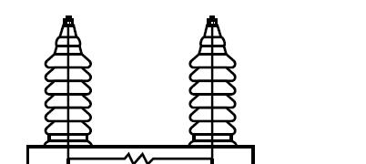
39 Capacitor Fundamentals Note that IEEE Std 18 requires the discharge resistor to reduce the terminal voltage to 50 V in the time frame as specified in the table below. Discharge resistor
40 Capacitor Ratings
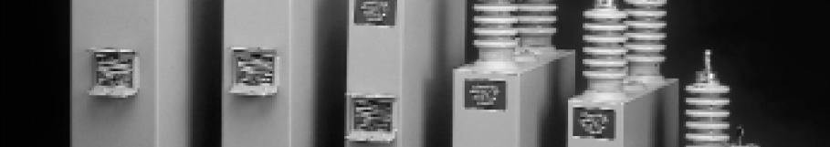
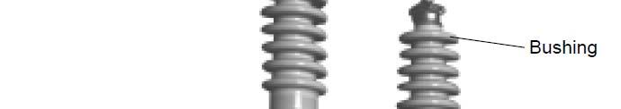
41 Capacitor Ratings Medium-voltage capacitors are available in many different styles. The main points of differentiation are listed below: Voltage rating kvar rating Single bushing or dual bushing Internally fused, externally fused, or fuseless
42 Capacitor Ratings IEEE 81 defines the ratings for capacitors Voltage, rms (terminal to terminal) Terminal-to-case (or ground) insulation class Reactive power Number of phases Frequency
43 Capacitor Ratings IEEE 18 provides capacitor tolerances The capacitance shall not vary more than -0% to +10% of nominal value based on rated kvar, voltage, and frequency measured at 25 deg C. This means that a new 150 kvar unit can range anywhere from 150 kvar to 165 kvar.
44 Capacitor Ratings IEEE 18 states the capacitor is intended to operate at or below rated voltage. Capacitors shall be capable of continuous operation given that none of the following limitations are exceeded: 110% of rated rms voltage (temporary overvoltage parameters will be discussed later) 120% of peak voltage, including harmonics but excluding transients 135% of nominal rms current based on rated kvar and rated voltage 135% of rated kvar
45 Capacitor Ratings * Impulse tests shall be applied between terminals and case, with the terminals connected together. For capacitors having bushings with two different BIL ratings, this test shall be based on the bushing with the lower BIL. The nameplate shall show both BIL ratings, e.g. 150/95 kv BIL. ** Not applicable to indoor ratings
46 Capacitor Application
47 Capacitor Application Power factor correction capacitor banks are typically installed in the following ways : Pole top Metal-Enclosed / Pad-Mount Open rack Terminal end at equipment
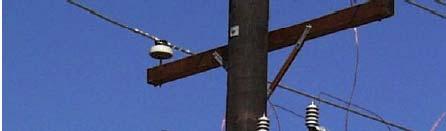
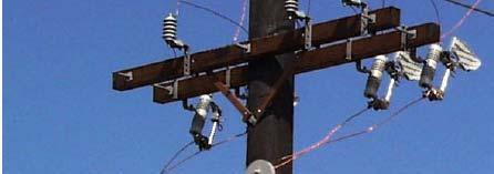
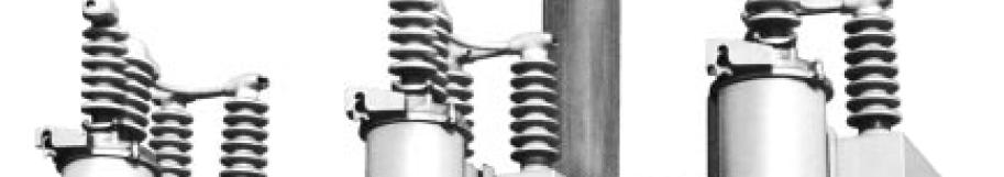
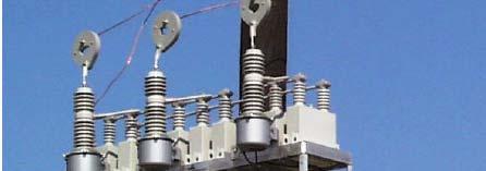

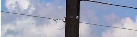
48 Capacitor Application Pl Pole Top Installation tllti
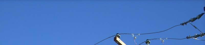
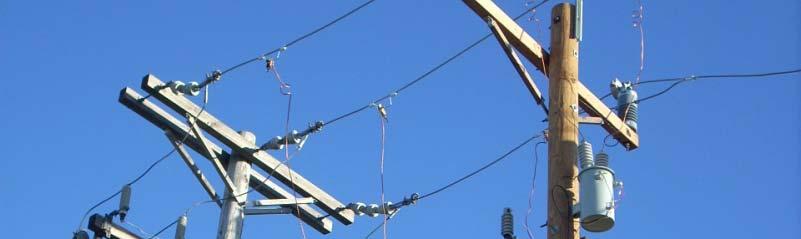
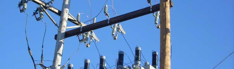
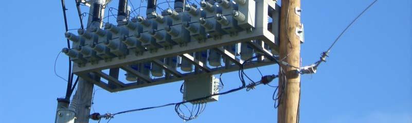

49 Capacitor Application Transient inrush reactors Pl Pole Top Installation tllti


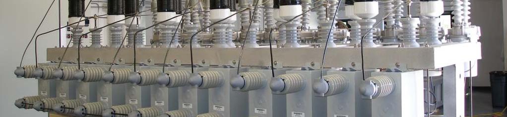
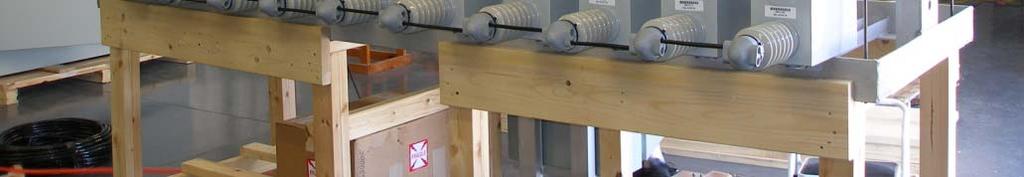
50 Capacitor Application Pad-Mounted Installation

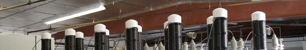
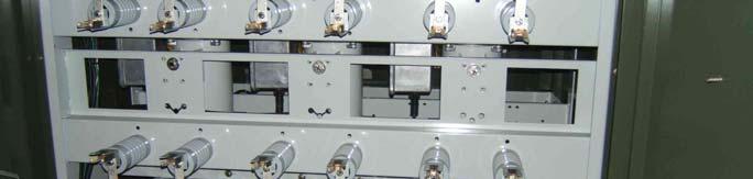
51 Capacitor Application Metal-Enclosed Substation Installation
52 Capacitor Application Three-phase iron core harmonic filter reactor Metal-Enclosed Substation Installation
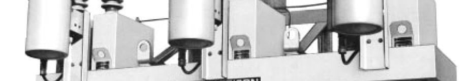
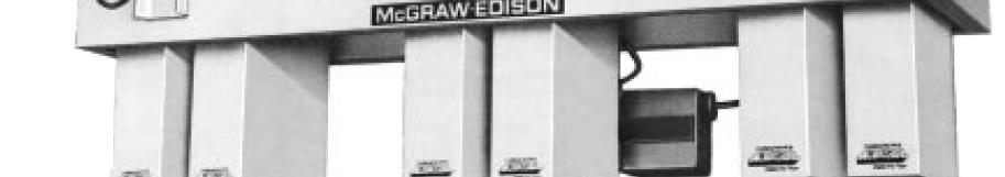
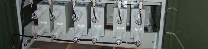
53 Capacitor Application Open Rack, Medium-Voltage Substation Installation
54 Capacitor Application Open Rack, High-Voltage Substation Installation


55 Capacitor Application Installation in Equipment
56 Capacitor Application Power factor correction capacitor banks can be configured in the following ways : Delta Wye - Solidly Grounded Wye - Ungrounded A common misconception is that the capacitor bank should be connected Delta since it is being applied to a delta or highimpedance grounded system. This is NOT true.
57 Capacitor Application The driving factor which determine the configuration for the given application is COST. Voltage considerations IEEE 1036 suggests that only banks rated 2400 V and below should be Delta connected. This is mainly because standard voltage ratings for wye connected banks may not be available. Cost of phase-to-phase vs phase-to-neutral rated capacitors at higher voltages tends to point installations towards wye connected banks for larger bank installations.
58 Capacitor Application Delta Lower voltages (<= 2400 V) Standard capacitors are typically not available at 1380 V Distribution systems (pole top) Units are configured with a single series group of capacitors with capacitors rated phase-to-phase. Therefore, unbalance detection is not required.
59 Capacitor Application Wye Solidly Grounded Initial cost of the bank may be lower since the neutral does not have to be insulated from ground. Capacitor switch recovery voltages are reduced High inrush currents may occur in the station ground system The grounded-wye d arrangement provides a low-impedance fault path which may require revision to the existing system ground protection scheme. Typically ynot applied to ungrounded systems. When applied to resistance-grounded systems, difficulty in coordination between capacitor fuses and upstream ground protection relays (consider coordination of 40 A fuse with a 400 A grounded system). Typical for smaller installations (since auxiliary equipment is not required)
60 Capacitor Application The most common capacitor bank configurations for larger substation applications are Wye-Ungrounded Three of the most common unbalance protection schemes are shown. Discussion of the protection schemes will be presented later.


61 Capacitor Protection Fusing Fuseless It Internally Fused Externally Fused
62 Capacitor Protection Bank kprotection ti Summary
63 Capacitor Protection Fuseless Capacitors Constructed of small capacitor elements which are arranged in series and parallel. The elements are constructed of aluminum foil with a dielectric of electrical grade polypropylene. This design provides a safe failure mode. In the event that the dielectric fails, the energy in the resulting small arc punctures many layers of the thin film and foil within the element. The arc causes the film layer to receded allowing many layers of the aluminum foil electrodes to touch and weld together forming an electrically stable electrical joint. This results in an entire series section being shorted.


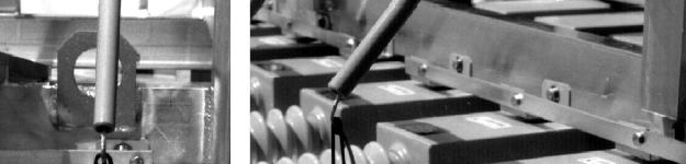
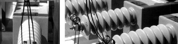
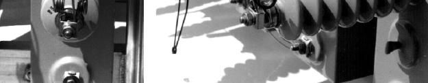
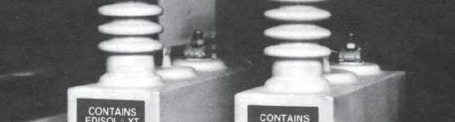
64 Capacitor Protection Example of Fuseless Installation


65 Capacitor Protection Internally Fused Capacitors Constructed such that each element is protected with a series connected current limiting fuse. The design is such that isolated fusing prevents potential damage to the adjacent elements and fuses. The current limiting mode chops the fault current to prevent the energy stored in the parallel connected elements from being discharged into the faulted element.
66 Capacitor Protection Group Fusing Individual dvdu Fusing
67 Capacitor Protection Group Fusing Considerations for Selecting Fuse (typical for distribution pole mounted racks) Continuous Current Transient Current Fault Current Tank Rupture Curve Coordination i Voltage on Good Capacitors
68 Capacitor Protection Continuous Current For wye-solidly grounded systems: Fuse > = 135% of rated capacitor current (includes overvoltage, capacitor tolerances, and harmonics). For wye-ungrounded systems: Fuse > = 125% of rated capacitor current (includes overvoltage, capacitor tolerances, and harmonics). Care should be taken when using NEMA Type T and K tin links which are rated 150%. In this case, the divide the fuse rating by 1.50.
69 Capacitor Protection Transient Current Capacitor switching (specifically back-to-back switching) Lightning surges Back-to-back is typically y not a factor for pole mounted capacitors banks. High frequency lightning surges: High frequency lightning surges: Use NEMA T tin links for ampere ratings up to 25 A. Use NEMA K tin links for ampere ratings above 25 A.
70 Capacitor Protection Fault Current Ensure that the fuse can interrupt the available fault current Tank Rupture Coordination Ensure that the fuse maximum clearing TCC curve for the fuse link is plotted below the capacitor tank rupture curve. In cases of high fault currents, the tank rupture curve should be compensated for asymmetry. Voltage on Good Capacitors For an ungrounded ddsystem, a fault on one phase results in a 1.73 times overvoltage on the un-faulted phases. Ensure that the fault is cleared before the second capacitor failure.
71 Capacitor Protection Problems with Fusing of Small Ungrounded Banks Consider a kv, 1500 kvar cap bank made of three (3) 500 kvar single-phase units. 1500[ kvar] [ kv ] 69.44[ A] [ A] 100[ A] Fuse If a capacitor fails, we will expect approximately 3x line current. It will take a 100 A fuse approximately 500 seconds to clear this fault (3 x A = A). The capacitor case will rupture long before the fuse clears the fault. The solution is using smaller units (explanation to follow).
72 Capacitor Protection Individual Fusing Considerations for Selecting Fuse (typical for substation capacitor banks) Continuous Current Transient Current Fault Current Tank Rupture Curve Coordination Voltage on Good Capacitors Energy Discharge into Faulted Unit Outrush Current Coordination with Unbalance Detection System
73 Capacitor Protection Continuous Current Fuse > = 135% of rated capacitor current (includes overvoltage, capacitor tolerances, and harmonics) Care should be taken when using NEMA Type T and K tin links which are rated 150%. In this case, the divide the fuse rating by 1.50.
74 Capacitor Protection Transient Current Lightning surges Capacitor switching (specifically back-to-back switching) High magnitude, high frequency lightning gsurges are typically ynot a concern for substation installations. Back-to-back switching is typically controlled with pre-insertion closing resistors or current limiting reactors. h f i ll i h ll l f ill h h By the nature of installation, the parallel fuses will share the transient current and will not be a factor.
75 Capacitor Protection Fault Current Ensure that the fuse can interrupt the available fault current. In substation banks with multiple series groups, fault current will not flow through a failed capacitor unit unless other units experience a simultaneous failure. For this reason expulsion fuses are commonly used rather than current limiting fuses Tank Rupture Coordination Ensure that the fuse maximum clearing TCC curve for the fuse link is plotted below the capacitor tank rupture curve. In cases of high fault currents, the tank rupture curve should be compensated for asymmetry. y
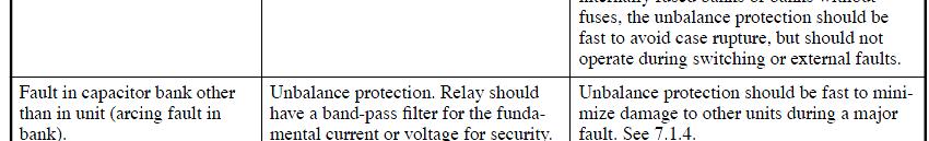
76 Capacitor Protection Example of a Definite Tank Rupture Curve. Th i b h The time between the rupture curve and the fuse maximum clear curve is the coordination margin.
77 Capacitor Protection Example of a 10% and 50% Rupture Curve for a 100 kvar Capacitor. Probability based tank rupture curves are developed when there is too much variance in rupture test data. Based on the 10% and 50% curves, one can extrapolate the curves for any probability. bili
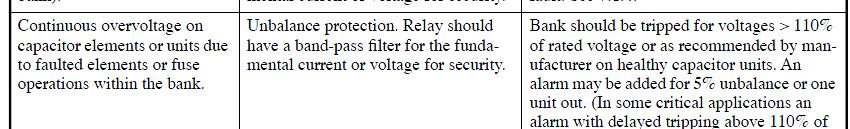
78 Capacitor Protection Voltage on Good Capacitors When a short-circuit on one unit occurs, an overvoltage results on the un-faulted phases. Ensure that the fault is cleared before the second capacitor failure. A table summarizes this voltage rise on the un-faulted units Per Unit Voltage on Un-failed Capacitors
79 Capacitor Protection Energy Discharge Into a Failed Unit When a capacitor failure occurs, the stored energy in the parallel connected capacitors can discharge through the failed capacitor and its fuse. The total calculated parallel stored energy should not exceed the energy capability (Joule rating) of the capacitor and fuse. If the energy capabilities are exceeded, a failure of the fuse and/or rupture of the capacitor tank can result. Typical rating of film capacitors is 15,000 Joules (4650 kvar in parallel) and 10,000 Joules (3100 kvar in parallel) for paper- film capacitors. Expulsion fuses are typically rated 30, Joules. Current limiting fuses are required if ratings are exceeded. (1 Joule = 1 W x sec, use 0.2 cycle clearing time for calculation)
80 Capacitor Protection Outrush Current When a capacitor failure occurs, the parallel connected capacitors can discharge high frequency current into the failed capacitor. The fuses of the un-failed capacitors should be able to withstand the high frequency discharge currents. These calculations and measurements are complex and are determined by the manufacturer. Coordination with Unbalance Detection Scheme The individual fuse must clear the fault before the unbalance protection scheme trips the entire capacitor bank.
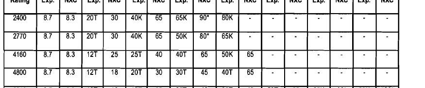
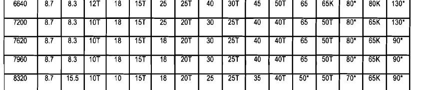
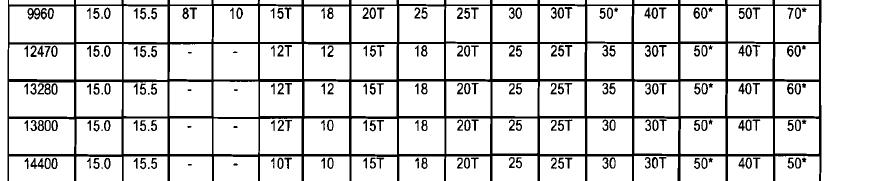
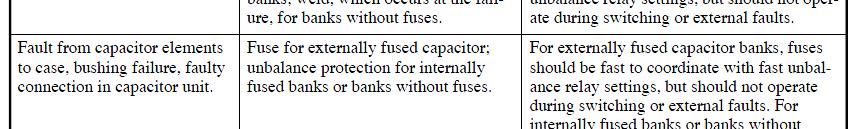
81 Capacitor Protection Fusing Recommendations by McGraw Edison
82 Capacitor Protection Recall Problem with Fusing of Small Ungrounded Banks kv, 1500 kvar cap bank made of three (3) 500 kvar units 1500[ kvar] [ kv ] 69.44[ A] [ A] 100[ A] Fuse It will take a 100 A fuse approximately 500 seconds to clear this fault (3 x A = A). The capacitor case will rupture long before the fuse clears the fault. The solution is using smaller units with individual fusing. Consider five (5) () 100 kvar capacitors per phase, each with a 25 A fuse. The clear time for a 25 A A is below the published capacitor rupture curve.


83 Capacitor Protection Why is the Current 3 x Nominal Line Current for a Phase-to- Neutral Fault on a Wye-Ungrounded Capacitor Bank? B B A N A N V NG C C Since V = I*Z, where Z is constant (assuming f = 60 hz) If voltage across capacitor is increased by 1.732, the current also increases by factor of t t( i f 60h ) I A = p.u.
84 Capacitor Protection Minimum Conductor Size It was noted that capacitors are rated 135% of rating. This requires the conductor to be sized 135% of the nominal capacitor rating.
85 Capacitor Protection Unbalance Protection As single-phase units in a multiple unit/phase installation fail and are removed from service, the remaining units are experience an overvoltage condition. IEEE Standard 1036 provides overvoltage limitations. Duration Max Voltage (x rated RMS) 6 cycles cyclescles s sec min 1.30 An unbalance protection scheme must by implemented to prevent the failure of the overvoltaged units.
86 Capacitor Protection
87 Capacitor Protection Neutral Voltage Unbalance with Unbalance Compensation
88 Capacitor Protection V A V NG V G V N Normal Conditions V N = V G V AN = V BN = V CN V C V B
89 Capacitor Protection Ungrounded or Impedance Grounded System V A V NG V G V N Normal Conditions V N = V G V AN = V BN = V CN = 1.0 p.u. V C V B
90 Capacitor Protection V NG Phase to Neutral Fault Phase to Neutral Fault V NG = V LN V AN = V BN = V LL = p.u.


91 Capacitor Protection V A V NG V G V N One Can Removed V NG = 0.2 p.u. V CN =12pu 1.2 p.u. V C V B


92 Capacitor Protection Ungrounded or Impedance Grounded System V A V NG V G V N Normal Conditions V N = V G V AN = V BN = V CN = 1.0 p.u. V C V B


93 Capacitor Protection Ungrounded or Impedance Grounded System Gnd V A V NG V N Ground Fault V NG = V LN V AG =V BG =V LL = pu p.u. V C V C =V G Ground Fault at Cap Bank or Anywhere on the System V B


94 Capacitor Protection Wye-Ungrounded: Voltage Between Capacitor Bank Neutral and Ground vs. Percentage of Capacitor Units Removed from Series Group

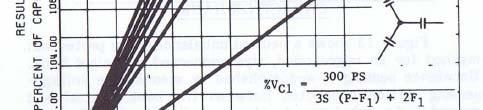
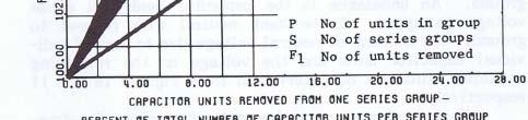
95 Capacitor Protection Wye-Ungrounded: Voltage on Remaining Capacitor Units in Series Group vs. Percentage of Capacitor Units Removed from Series Group


96 Capacitor Protection Wye-Grounded: Neutral Current vs Percentage of Capacitor Units Removed from Series Group

97 Capacitor Protection Wye-Grounded or Delta: Voltage on Remaining Units in Series Group vs. Percentage of Capacitor Units Removed from Series Group


98 Capacitor Protection Double Wye-Ungrounded, Neutrals Tied Together: Neutral Current vs. Percentage of Capacitor Units Removed from Series Group


99 Capacitor Protection Double Wye-Ungrounded, Neutrals Tied Together: Voltage on Remaining Capacitor Units in Series vs. Percentage of Capacitor Units Removed from Series Group
 S: Number of series groups (S=4) Reference Figure for Calculations to")
100 Capacitor Protection A phase B phase C phase P: Number of units in group (P=6) S: Number of series groups (S=4) Reference Figure for Calculations to Follow
101 Capacitor Protection # of Series Groups Grounded Y or Delta Ungrounded Y Split Ungrounded Y (equal sections) and over Minimum recommended number of units in parallel per series Group to limit voltage on remaining units to 110% with one unit out
102 Capacitor Protection Many more configurations and calculations shown in IEEE C37.99
103 Day 2
104 Capacitor Fundamentals Further discussion on capacitor voltage ratings: On a ungrounded or impedance grounded system, a ground fault on one phase will cause the other two phases will be elevated by Does this mean that capacitors must be rated phase-to-phase? Certainly nothing wrong with this, but cost will be significantly higher.
105 Capacitor Fundamentals Recall: S V X 2 X C This means that a 150 kvar, V unit applied at 7200 V will provide only 50 kvar. S NEW [ V ] 12470[ V ] S NEW 50[ kvar ] 2 150[ kvar]
106 Capacitor Fundamentals Using V capacitors on a V Ungrounded or Resistance-Grounded System will require 3x more cans. It should be noted that the V cans will also be larger than the 7200 V cans. Results in a much larger and more costly installation. This solution would be required if a ground fault could be maintained for extended periods of time.
107 Capacitor Fundamentals Perhaps a 150 kvar or 200 kvar, 7620 V or 7960 V units applied at 7200 V would be a better solution. S NEW 7200[ V ] 7620[ V ] S NEW 134[ kvar] OR S NEW 7200[ V ] 7960[ V ] S NEW 123[ kvar ] [ kvar] 150[ kvar] S NEW 7200[ V ] 7620[ V ] S NEW 178[ kvar] OR S NEW 7200[ V ] 7960[ V ] S NEW 163[ kvar ] 2 200[ kvar] [ kvar] Note that the 7620 V unit provides an additional 6% The 7960 V unit provides an additional 11%
108 Explusion Fuses: Capacitor Fundamentals Provides a means of disconnecting a failed capacitor from the circuit by melting a tin-lead low current link. The shorted capacitor unit causes a large increase in the current through the fuse. The current is limited only by the power system reactance and the other capacitor units in series with the failed capacitor unit. The pressure is generated by the hot arc making contact with the fiber lining of the fuse tube. The link is cooled and stretched as it is forced out the tube. The fuse continues to conduct until a natural current zero occurs. The current zero is caused by the power system fault current crossing zero. If other capacitors are connected in parallel with the failed unit, all the stored energy in these capacitors will be absorbed in either the fuse operation or the failed capacitor unit. Most of the energy is absorbed in the failed capacitor.
109 Capacitor Fundamentals Current Limiting Fuses: Uses a long uniform cross section element. This configuration makes the fuse a current chopping fuse. The fuse develops a back voltage per inch of element across the entire length of the element. When this voltage exceeds the available voltage across the fuse, the fuse forces the arc to extinguish. The result is that a trapped voltage may and probably will remain on the other capacitors in the series group. The fuse by its design avoids absorbing all of the available energy on the series group. This fuse is used for capacitor banks with a large number of parallel l capacitors. It can be used on applications with essentially infinite it parallel l stored energy, as long as sufficient back voltage can be developed to force the current to extinguish. This is the fuse we apply to series, large shunt, and DC banks. Because of the high back voltage that is developed, this fuse must be used with several capacitors in parallel to limit the voltage build up or a flashover may occur elsewhere in the capacitor rack.
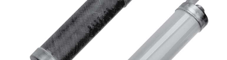
110 Capacitor Fundamentals Current Limiting Fuses vs Expulsion Fuses: Expulsion Fuse Current Limiting i i Fuse
111 Capacitor Fundamentals Current Limiting Fuses vs Expulsion Fuses: Expulsion Fuses Operate mechanically and provide a visual indication Require additional space for operation Typically applied for outdoor application due to ionized gas release. Combination expulsion with current limiting iti characteristic ti fuses can be used in indoor metal-enclosed equipment. Less expensive


112 Capacitor Fundamentals
113 Capacitor Fundamentals Current Limiting Fuses Do not emit ionized gases during operation. Ionized gases are undesirable because they can cause bushing and insulator flashovers that result in additional damage. Do not require ventilation. Fast current-limiting operation High interrupting capacity, noiseless operation Can be specified for indoor and outdoor applications. No pressure build-up, therefore, no vents or special reinforced compartments are required. More expensive

114 Capacitor Fundamentals Note no pigtail and blown fuse indication

115 Capacitor Fundamentals Current Limiting with Expulsion
116 Capacitor Fundamentals What about arresters? How and where should they be applied? Depending on application, environment, exposure to switching, etc, arresters may be necessary. We recall that when a travelling wave meets a high impedance, the wave can double in size. For this reason, arresters (if used) should be installed as close to the capacitor bank as possible. Installation of arresters at the breaker feeding the capacitor bank will not do much for protection of the capacitor bank.
117 Capacitor Protection A basic three (3) arrester method is shown below. This is typical for solidly grounded systems and wye-grounded capacitor banks.
118 Capacitor Protection Depending on type of installation, system parameters and level of protection required, a six(6) arrestor method may be applied.
119 Capacitor Protection For an ungrounded system or a high-impedance grounded system, a four (4) arrestor grounding method might be considered an wye ungrounded bank. Phase to Neutral Fault V NG = V LN V AN = V BN = V LL = p.u. Ground Fault V NG = V LN V AG = V BG = V LL = p.u. If faults can be maintained, V LL V LL Arr PH Arr PH must be rated V LL Arr N must be rated V LN Arr N The effective arrester MCOV is V LL + V LN
120 Capacitor Protection Note that if a basic three (3) arrester method is applied to an ungrounded bank, the arresters must be rated high enough to sustain a temporary overvoltage condition during a phase-toground fault on the system. This may not provide an adequate level of protection for the capacitors. Phase to Neutral Fault V NG = V LN V AN = V BN = V LL = p.u. Ground Fault V NG = V LN V AG = V BG = V LL = p.u. If faults can be maintained, Arresters must be rated V LL Arresters do not provide protection across the capacitor bushings. Note that the BIL applies to bushing-to- case insulation. V LL V LL
121 Capacitor Protection Good Presentations on Capacitor Arrester Applications Guidelines for Selection of Surge Arresters for Shunt Capacitor Banks ABB Technical Information Surge Arrester Application of MV-Capacitor Banks to Mitigate Problems of Switching Restrike CIRED 19 th International Conference on Electricity Distribution, Vienna, May B th fth l dd h t h t Both of these papers also address phase-to-phase arrester connections.
122 Harmonics
123 Harmonics Recall that the impedance of a capacitor is inversely proportional to the system frequency. X C 1 1 C 2 fc Harmonics flow to the point of lowest impedance. The higher the harmonic, the lower the impedance of the capacitor. As capacitors absorb harmonics, the capacitor heats up and the life expectancy is reduced. d The voltage harmonics stress the capacitor dielectric and reduce the life expectancy of the capacitor.
124 Harmonics
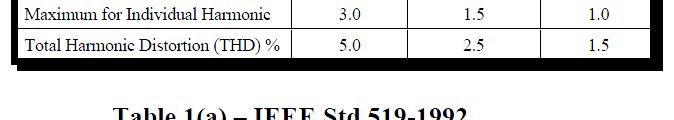
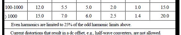
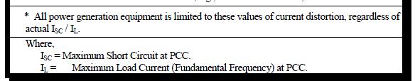
125 Harmonics Where do harmonics come from? Power Electronics (drives, rectifiers, computer power supplies, etc) Arcing Devices (welders, arc furnaces, florescent lights, etc) Iron Saturating Devices (transformers) Rotating Machines (Generators) Parallel Resonance (between cap bank and power equipment) IEEE Std 519 provides recommended limits of harmonic distortion at the point-of-common-coupling (PCC) with the utility.
126 Harmonics
127 Harmonics
128 Harmonics Resonance When a number of harmonic current sources are injecting currents into the supply and the frequency of one of the harmonics coincides with the resonant frequency of the supply transformer and Power Factor Correction capacitor combination, the system resonates and a large circulating harmonic current is excited between these components. The result of this is that a large current at this harmonic flows in the supply transformer, this resulting in a large harmonic voltage distortion being imposed upon the load voltage.
129 Harmonics A study should be performed to determine levels of harmonics on a system to determine if any filters are necessary when installing a capacitor bank. Care should be taken to determine if the filtered capacitor bank will introduce any resonance problems. If resonance problems exist, the filter design must be adjusted. d


130 Harmonics An example of a 13.8 kv harmonic filter
131 Capacitor Bank Design Considerations
132 Design Considerations So how do we size a capacitor bank? Dt Determine your primary goal Voltage support Lower utility bill (avoid penalties) Increase capacity of system It can be all three, or any combination of the above. Note that correcting to unity power factor at maximum load is costly and may not be necessary.
133 Design Considerations For a 20 MVA load at 0.88 power factor (17.6 MW, 9.5 MVAR) To achieve 95% power factor, a 3.72 MVAR bank is required To achieve 98% power factor, a 5.93 MVAR bank is required To achieve unity power factor, a 9.50 MVAR bank is required
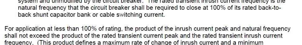
134 Design Considerations Determine if current limiting reactors or tuning reactors are required. Harmonics and resonance may dictate tuning reactors Back-to-back switching may require current limiting reactors (unless another method is used to mitigate the switching surges, i.e. pre-insertion closing resistors/reactors, zero-crossing breakers, etc)
135 Design Considerations Determine the proper voltage. Capacitors are very susceptible to voltage transients and harmonics. Increasing the rated voltage increases the protective margin on the insulation. The voltage at the capacitor terminals will be higher than bus voltage if reactors are utilized. It is important t to account for this voltage difference. Determine the voltage swing of the system. Will the capacitors remain on-line while the facility is lightly loaded.
136 Design Considerations We listed some reasons for specifying higher than bus nominal rating of capacitors. However, care must be taken to ensure that the kvar rating is properly adjusted as a result. Three (6) 150 kvar, 7960 V wye-connected capacitors provide a nominal 901 kvar when connected to a 13.8 kv bus. Three (6) 150 kvar, 8320 V wye-connected capacitors provide a nominal 825 kvar when connected to a 13.8 kv bus
137 Design Considerations Determine optimal size and number of stages. Depending on swing in plant tload, a single bank sized dfor full plant capacity may not be the answer. IEEE 1036 recommends limiting the voltage change to 2-3%. The delta voltage can be estimated by: V MVAR 100% MVA SC Switch of a capacitor applies high stresses to the insulation. Limiting the number of stages and limiting the frequency of switching will increase the life. Ideally, a capacitor is switched on and left on.
138 Design Considerations Determine best location for the installation. The most effective placement for power factor correction capacitor banks is at the load. However, this is not always practical or cost effective. Typically, a capacitor bank is installed on each bus of a main-tie- main switchgear. If capacitors are installed at the motor pecker head (running capacitors), ensure that the capacitor VAR rating does not exceed 90% of the motor no-load VAR. Otherwise, it is possible to damage the motor by overexcitation.
139 Design Considerations Use caution when sizing motor running capacitors. Logic would suggest that installation of a power factor correction capacitor at the motor terminals sized to provide unity ypower factor makes sense. THIS IS NOT THE CASE. Do not exceed 90% of the motor no-load kvar demand. Exceeding this value can result in damage to the motor insulation as a result of overexcitation.
140 Design Considerations As an example for a 4000 V, 4000 hp motor: 100% load current = % pf 100% load kvar = 1516 kvar No load current = % pf No load kvar = 809 kvar Max size of running capacitor is 0.90 x 809 kvar = 728 kvar
.")

141 Design Considerations M: Motor Magnetizing Curve C1: Capacitor size at 100% motor mag current C2: Capacitor sized > 100% motor mag current C4: Capacitor sized < 100% motor mag current If the capacitive reactance of the capacitor is less less than that of the motor reactance (this occurs when to large of a capacitor is chosen). This combination of reactance will result in a resonant frequency below 60 hertz. Therefore, as the motor slows in speed, the frequency of the motor terminal voltage will decrease from a value of near 60 hertz toward zero. When the motor's terminal voltage frequency passes through the resonant frequency setup between the capacitor reactance and the motor reactance, the terminal voltage will become very high, only limited by the properties of the iron. Depending on the inertia of the motor, this resonance (or high voltage) may be present for a considerable period of time.
142 Design Considerations Determine the most optimal type of installation. Will the capacitor bank be installed within a fenced substation? Metal-enclosed, pad mount, or open rack may be good choices Will the capacitor bank be installed in a process area? Metal-enclosed or pad mount may be good choices Will the capacitor bank be pole mounted on a distribution line?

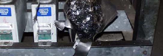
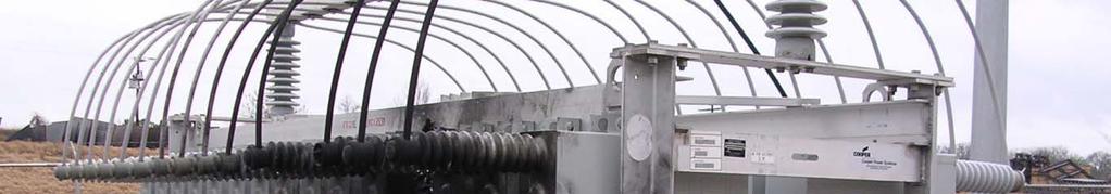
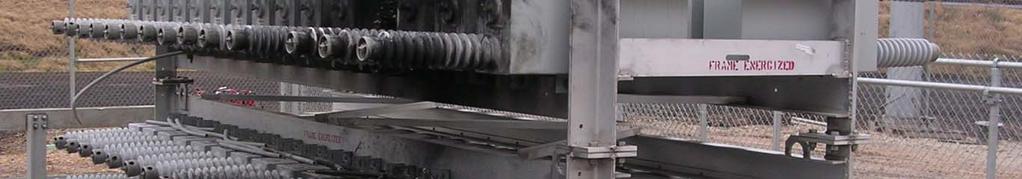
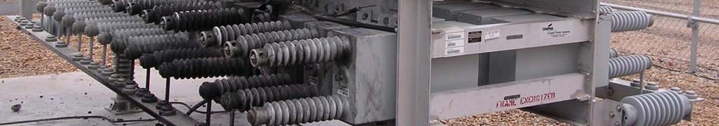
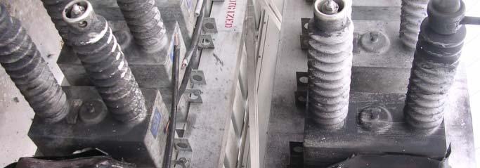
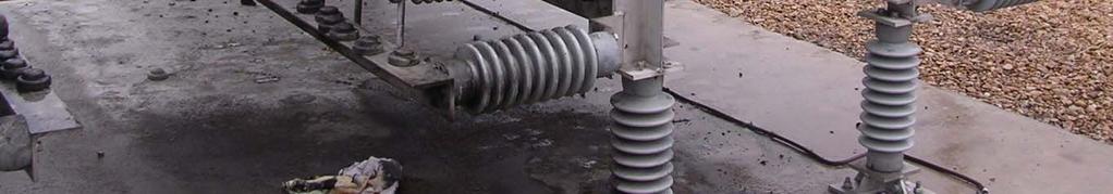
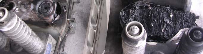
143 Bank Failures
144 Design Considerations Consider the impact to personnel safety adjacent equipment when deciding between a metal-enclosed and open-rack system. Porcelain can resemble shrapnel when a capacitor bushing fails.
145 Design Considerations Determine the most optimal configuration. Higher reliability costs more kvar, V, wye-grounded (1) 800 kvar per phase bank will be a smaller footprint and cost less than 2400 kvar, V, wye-ungrounded (8) 100 kvar per phase bank. H h li bili f h d d b k i However, the reliability of the wye-ungrounded bank is significantly higher
146 Design Considerations Determine the switching equipment When breakers are used for switching capacitors (single bank or back-to-back switching), the breakers must be rated for capacitor switching. IEEE C37.99 provides the equations for calculating the inrush current and frequency.
147 Design Considerations
148 Design Considerations Consider a single 4800 kvar wye-ungrounded bank switched (with nominal inductance from equipment): 3253A 600 Hz, the product is 0.20 x 10 7 Switching a second similar bank on the same bus without current limiting reactor: 24,058 A 7.66 khz, the product is 18.4 x 10 7 By adding a 100 mhh current limiting i i reactor, the inrush is: 7254 A 2.31 khz, the product is 1.7 x 10 7
149 Design Considerations
150 Design Considerations
151 Design Considerations Energization of a single capacitor bank.
152 Design Considerations Back-to-back kswitching of the same unit.
153 Design Considerations Example of fbreaker with pre-insertion i resistor.
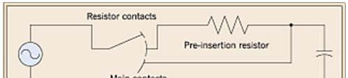
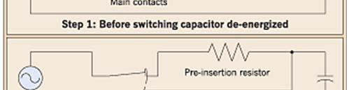
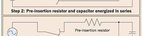
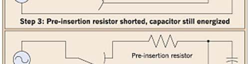
154 Design Considerations Another application.
155 Design Considerations A Pre-Insertion Manufacture s Perspective.
156 Design Considerations Another concern is voltage amplification as a result of switching a second capacitor bank.
157 Design Considerations
158 Design Considerations Consider other accessories: Disconnect switch Grounding switch Kirk-key interlock Ventilation requirements Control power
159 Design Considerations
160 Design Considerations
161 Design Considerations Be aware that larger medium voltage motors may include surge packs. The surge pack will decrease the crest voltage and rate of rise of the impending surge. High rates of rise damage end turns while high crest voltage damage winding to core insulation. Typically the capacitance of the is small enough that it can be neglected, but this should be verified.
162 Design Considerations Typical Surge Pack Application
163 Design Considerations Do not confuse Harmonic Filter Banks with Power Factor Correction Banks. The voltage ratings of harmonic filter banks are substantially higher because they are connected on the back end of a tuning reactor where the voltage is substantially higher. As a result of the higher voltage, the installed kvar can be anywhere e from 25% to 40% higher than nominal design. The capacitor cans must be capable of this output.
164 Grounding of Wye Banks If multiple wye-grounded banks are in close proximity, use peninsula grounding g or single-point grounding. g Single-Point Grounding The neutrals of all banks of a given voltage are connected together with insulated cable/bus and tied to the ground grid only at one point. This prevents high-frequency currents (due to back-to-back b kswitching) )from flowing into the ground grid.
165 Grounding of Wye Banks Peninsula Grounding One or more isolated ground grid conductors are carried underneath the capacitor rack of each phase and tied to the station ground grid at one point at the edge of the capacitor area. All capacitor bank neutral connections are made to this isolated peninsula ground grid conductor.
166 Grounding of Wye Banks
167 Grounding of Wye Banks
168 References IEEE Std. 18 IEEE C37.99 NEMA CP-1 IEEE Std 1036 IEEE Std 399 (Brown Book)
Tutorial on Shunt Capacitor Banks Design, Application and Protection Considerations
 Tutorial on Shunt Capacitor Banks Design, Application and Protection Considerations Presenter: Pratap Mysore, HDR Minnesota Power Systems Conference November 12, 2015 Topics Covered Power system Considerations,
CHAPTER 2 OVERVOLTAGE DUE TO SELF-EXCITATION AND INRUSH CURRENT DUE TO CAPACITOR SWITCHING
 20 CHAPTER 2 OVERVOLTAGE DUE TO SELF-EXCITATION AND INRUSH CURRENT DUE TO CAPACITOR SWITCHING 2.1 INTRODUCTION It is becoming more common to find use of shunt capacitors for the application of powerfactor
Capacitor Application Issues
 Capacitor Application Issues Thomas Blooming, P.E. Daniel J. Carnovale, P.E. IEEE Industry Applications Society 53 rd Pulp & Paper Industry Technical Conf. Williamsburg, Virginia June 24-29, 2007 Introduction
SSC-JE EE POWER SYSTEMS: GENERATION, TRANSMISSION & DISTRIBUTION SSC-JE STAFF SELECTION COMMISSION ELECTRICAL ENGINEERING STUDY MATERIAL
 1 SSC-JE STAFF SELECTION COMMISSION ELECTRICAL ENGINEERING STUDY MATERIAL Power Systems: Generation, Transmission and Distribution Power Systems: Generation, Transmission and Distribution Power Systems:
Fault Calculation Methods
 ELEC9713 Industrial and Commercial Power Systems Fault Calculation Methods There are two major problems that can occur in electrical systems: these are open circuits and short circuits. Of the two, the
Power System Analysis Prof. A. K. Sinha Department of Electrical Engineering Indian Institute of Technology, Kharagpur
 Power System Analysis Prof. A. K. Sinha Department of Electrical Engineering Indian Institute of Technology, Kharagpur Lecture - 9 Transmission Line Steady State Operation Welcome to lesson 9, in Power
High Voltage Capacitors Designed to Avoid Catastrophic Failure Modes
 GENERAL ATOMICS ENERGY PRODUCTS Engineering Bulletin High Voltage Capacitors Designed to Avoid Catastrophic Failure Modes F. W. MacDougall G. L. McKee, J.B. Ennis, R.A. Cooper Maxwell Energy Products,
Selecting the current rating for equipment
 Selecting the current rating for equipment 1. Rated current: the maximum continuous load current. Short-time withstand current: thermal withstand current term term is given for 1s or 3s short circuit current
EE2351 POWER SYSTEM OPERATION AND CONTROL UNIT I THE POWER SYSTEM AN OVERVIEW AND MODELLING PART A
 EE2351 POWER SYSTEM OPERATION AND CONTROL UNIT I THE POWER SYSTEM AN OVERVIEW AND MODELLING PART A 1. What are the advantages of an inter connected system? The advantages of an inter-connected system are
Chapter 3 AUTOMATIC VOLTAGE CONTROL
 Chapter 3 AUTOMATIC VOLTAGE CONTROL . INTRODUCTION TO EXCITATION SYSTEM The basic function of an excitation system is to provide direct current to the field winding of the synchronous generator. The excitation
GENERATOR INTERCONNECTION APPLICATION
 GENERATOR INTERCONNECTION APPLICATION FOR BUY-ALL/SELL-ALL PROJECTS WITH AGGREGATE GENERATOR OUTPUT OF MORE THAN 20 KW BUT LESS THAN OR EQUAL TO 1 MW Electric Utility Contact Information Great Lakes Energy
KINGS COLLEGE OF ENGINEERING Punalkulam
 KINGS COLLEGE OF ENGINEERING Punalkulam 613 303 DEPARTMENT OF ELECTRICAL AND ELECTRONICS ENGINEERING POWER SYSTEM ANALYSIS QUESTION BANK UNIT I THE POWER SYSTEM AN OVERVIEW AND MODELLING PART A (TWO MARK
1. Explain the various methods of methods of grounding. In power system, grounding or earthing means connecting frame of electrical equipment (non-cur
 1. Explain the various methods of methods of grounding. In power system, grounding or earthing means connecting frame of electrical equipment (non-current carrying part) or some electrical part of the
Damping resistor design consideration
 http : //www.cigre.org CIGRÉ B4-054 CIGRÉ Winnipeg 2017 Colloquium Study Committees A3, B4 & D1 Winnipeg, Canada September 30 October 6, 201717 Damping resistor design consideration Elassad Yann MS Resistances
POWER FACTOR IN THE DIGITAL AGE A N E N V I R O N M E N T A L P O T E N T I A L S W H I T E P A P E R. Power Quality For The Digital Age
 Power Quality For The Digital Age POWER FACTOR IN THE DIGITAL AGE A N E N V I R O N M E N T A L P O T E N T I A L S W H I T E P A P E R Introduction One method to measure the efficiency of the electrical
Chapter 15 Power And Harmonics in Nonsinusoidal Systems
 Chapter 15 Power And Harmonics in Nonsinusoidal Systems 15.1. Average power in terms of Fourier series 15.2. RMS value of a waveform 15.3. Power factor THD Distortion and Displacement factors 15.4. Power
Low Frequency Transients
 Page 1 IEEE Power Engineering Society Summer Meeting Edmonton, July 18-22, 1999 Tutorial: Power System Overvoltages Low Frequency Transients Presented by Bruce Mork Work Done by Slow Transients Task Force
Cahier Technique N 13 Principe de réduction des courants d enclenchement des transformateurs
 Cahier Technique N 13 Principe de réduction des courants d enclenchement des transformateurs Numerical transformer inrush current minimizer Principle of the operation Rev 1.0 Document version information
Power capacitors in general
 INDEX Power capacitors in general..low VOLTGE CPCITORS MKP (Box )..PPM / MKP TECHNOLOGY..OPERTING CONDITION.. Voltage..mbient temperature.. Installation.. Discharge the capacitor.. Inrush current limitation..
Analysis of Very Fast Transients in EHV Gas Insulated Substations
 Analysis of Very Fast Transients in EHV Gas Insulated Substations A.Raghu Ram, k. Santhosh Kumar raghuram_a@yahoo.com,ksanthosheee@gmail.com Abstract: Gas insulated switchgear (GIS) has been in operation
Instruction. Vacuum Circuit Breaker Operator Module. Type 3AH 4.16kV to 38kV. Power Transmission & Distribution
 Instruction 0001-22-2--00 Vacuum Circuit Breaker Operator Module Type 3AH 4.16kV to 38kV Power Transmission & Distribution Hazardous voltages and high-speed moving parts. Will cause death, serious injury
SPECIFICATION SS 51/9 400KV COUPLING CAPACITORS FOR POWER LINE CARRIER SYSTEM
 INDEPENDENT POWER TRANSMISSION OPERATOR S.A. TNPRD/ SUBSTATION SPECIFICATION & EQUIPMENT SECTION January 2017 SPECIFICATION SS 51/9 400KV COUPLING CAPACITORS FOR POWER LINE CARRIER SYSTEM I. SCOPE This
Energy saving in electromechanical equipment with power coefficient correction. Dimitris Al. Katsaprakakis Aeolian Land S.A.
 Energy saving in electromechanical equipment with power coefficient correction Dimitris Al. Katsaprakakis Aeolian Land S.A. www.aiolikigi.gr Introduction Electricity production companies (utilities) provide
Chapter 21. Harmonic Analysis
 Chapter 21 Harmonic Analysis Because of the wide and ever increasing applications of power electronic devices, such as variable speed drives, uninterruptible power supplies (UPS), static power converters,
Fault Analysis Power System Representation
 .1. Power System Representation Single Line Diagram: Almost all modern power systems are three phase systems with the phases of equal magnitude and equal phase difference (i.e., 10 o ). These three phase
HIGH VOLTAGE CAPACITORS DESIGNED TO AVOID CATASTROPHIC FAILURE MODES
 HIGH VOLTAGE CAPACITORS DESIGNED TO AVOID CATASTROPHIC FAILURE MODES F. W. MacDougall G. L. McKee, J.B. Ennis, R.A. Cooper Maxwell Energy Products, Inc. San Diego, CA. R. M. Ness,- Cymer, Inc. San Diego
1..LOW VOLTAGE POWER CAPACITORS MKP (CYLINDRICAL) 2 2..PPM / MKP TECHNOLOGY 2 3..OPERATING CONDITION Voltage Ambient temperature
 2 2..PPM / MKP TECHNOLOGY 2 3..OPERATING CONDITION Voltage Ambient temperature") INDEX..LOW VOLTGE CPCITORS MKP (CYLINDRICL)..PPM / MKP TECHNOLOGY..OPERTING CONDITION.. Voltage..mbient temperature.. Installation.. Discharge the capacitor.. Inrush current limitation.. Harmonics.7.Overpresure
INDEX..LOW VOLTGE CPCITORS MKP (CYLINDRICL)..PPM / MKP TECHNOLOGY..OPERTING CONDITION.. Voltage..mbient temperature.. Installation.. Discharge the capacitor.. Inrush current limitation.. Harmonics.7.Overpresure
Transients on Integrated Power System
 Chapter 3 Transients on Integrated Power System 3.1 Line Dropping and Load Rejection 3.1.1 Line Dropping In three phase circuit capacitance switching, the determination of the voltage trapped after switching
Reactive Power Solutions
 GE Digital Energy Reactive Power Solutions Effects of Series Capacitors on Line Protection Relaying Design and Settings Presented by: Paul Datka, GE Energy Consulting Luis Polanco, GE Energy Consulting
THE EFFECT OF REVERSAL ON CAPACITOR LIFE
 GENERAL ATOMICS ENERGY PRODUCTS Engineering Bulletin 96-004 THE EFFECT OF REVERSAL ON CAPACITOR LIFE November 2003 2003 Sorrento Electronics, Inc. Capacitor Engineering Department General Atomics Energy
An Innovative Simple Test Circuit for Single-Phase Short Circuit Making Test of High-Voltage Switching Devices
 An Innovative Simple Test Circuit for Single-Phase Short Circuit Making Test of High-Voltage Switching Devices Downloaded from jiaeee.com at 2:32 +33 on Sunday November 4th 28 Abstract: N. Nikpour K. Niayesh
Analysis of factors affecting station capacitor bank switching transients
 Scholars' Mine Masters Theses Student Research & Creative Works 1971 Analysis of factors affecting station capacitor bank switching transients M. Davarpanah Follow this and additional works at: http://scholarsmine.mst.edu/masters_theses
Effects of Capacitor Bank Installation in a Medium Voltage (MV) Substation
 Substation") Effects of Capacitor Bank Installation in a Medium Voltage (MV) Substation Adesina, Lambe Mutalub Department of Engineering & Standardization, Eko Electricity Distribution Plc, 24/25, Marina, Lagos Island,
Effects of Capacitor Bank Installation in a Medium Voltage (MV) Substation Adesina, Lambe Mutalub Department of Engineering & Standardization, Eko Electricity Distribution Plc, 24/25, Marina, Lagos Island,
LO 1: Three Phase Circuits
 Course: EEL 2043 Principles of Electric Machines Class Instructor: Dr. Haris M. Khalid Email: hkhalid@hct.ac.ae Webpage: www.harismkhalid.com LO 1: Three Phase Circuits Three Phase AC System Three phase
F F FAULT CURRENT Prospective. 1. Introduction. 2. Types of fault conditions
 FAULT CURRENT F F13-13 FAULT CURRENT - Contents 1. Introduction 2. Types of fault conditions 3 fault current must be determined 3.1 Purposes for which of prospective fault current magnitudes are used 3.2
A. P. Sakis Meliopoulos and George J. Cokkinides Power System Relaying, Theory and Applications. Chapter 8 2 Generator Protection 2
 DRAFT and INCOMPLETE Table of Contents from A. P. Sakis Meliopoulos and George J. Cokkinides Power System Relaying, Theory and Applications Chapter 8 Generator Protection 8. Introduction 8. Generator Protection
Module 3 : Sequence Components and Fault Analysis
 Module 3 : Sequence Components and Fault Analysis Lecture 12 : Sequence Modeling of Power Apparatus Objectives In this lecture we will discuss Per unit calculation and its advantages. Modeling aspects
Determination of Fault Location in Shunt Capacitor Bank through Compensated Neutral Current
 International Journal of Advances in Scientific Research and Engineering (ijasre) E-ISSN : 2454-8006 DOI: http://dx.doi.org/10.7324/ijasre.2018.32630 Volume 4, Issue 3 March - 2018 Determination of Fault
Medium Voltage Capacitor Banks Characterization and Transients Generated
 Medium Voltage Capacitor Banks Characterization and Transients Generated S.G.Mohammad #, C.Gomes*, M.Z.A AbKadir* 3, Jasronita.Jasni* 4, M. Izadi* 5 Centre for Electromagnetic and ightning Protection Research
For the electronic measurement of current: DC, AC, pulsed..., with galvanic separation between the primary and the secondary circuit.
 Current Transducer LDSR 0.3-TP/SP1 I P R N = 300 ma For the electronic measurement of current: DC, AC, pulsed..., with galvanic separation between the primary and the secondary circuit. Features Closed
Modeling of Transmission Line and Substation for Insulation Coordination Studies
 TRAINING DUBROVNIK, CROATIA - APRIL, 27-29 2009 SIMULATION & ANALYSIS OF POWER SYSTEM TRANSIENTS WITH EMTP-RV Modeling of Transmission Line and Substation for Insulation Coordination Studies Prof. Ivo
THE DIMENSIONING OF ELECTRICAL CONDUCTORS FOR USE IN "PANEL BOARDS" ADDRESSED TO HAZARDOUS AREAS - PART THREE
 July 04 THE DIMENSIONING OF ELECTRICAL CONDUCTORS FOR USE IN "PANEL BOARDS" ADDRESSED TO HAZARDOUS AREAS - PART THREE In this third part. we want to speak about how important is the correct sizing of the
TRANSMISSION LINES. All aluminum alloy conductor (AAAC) Aluminum conductor alloy reinforced (ACAR)
 Aluminum conductor alloy reinforced (ACAR)") TRANSMISSION LINES. Transmission Structures An overhead transmission line consists of conductor, insulators, support structures and in most cases shield wires. Overhead power transmission lines are classified
TRANSMISSION LINES. Transmission Structures An overhead transmission line consists of conductor, insulators, support structures and in most cases shield wires. Overhead power transmission lines are classified
Western Electric A V a c u u m T u b e
 280A Western Electric 2 8 0 A V a c u u m T u b e Classification Half-wave, thermionic, mercury vapor rectifier The 280A vacuum tube is designed to supply direct current from an alternating-current supply.
The Basic Capacitor. Water Tower / Capacitor Analogy. "Partnering With Our Clients for Combined Success"
 CAPACITOR BASICS I How s Work The Basic A capacitor is an electrical device which serves to store up electrical energy for release at a predetermined time. In its most basic form, it is comprised of three
B.E. / B.Tech. Degree Examination, April / May 2010 Sixth Semester. Electrical and Electronics Engineering. EE 1352 Power System Analysis
 B.E. / B.Tech. Degree Examination, April / May 2010 Sixth Semester Electrical and Electronics Engineering EE 1352 Power System Analysis (Regulation 2008) Time: Three hours Answer all questions Part A (10
ECE 325 Electric Energy System Components 7- Synchronous Machines. Instructor: Kai Sun Fall 2015
 ECE 325 Electric Energy System Components 7- Synchronous Machines Instructor: Kai Sun Fall 2015 1 Content (Materials are from Chapters 16-17) Synchronous Generators Synchronous Motors 2 Synchronous Generators
Generators. What its all about
 Generators What its all about How do we make a generator? Synchronous Operation Rotor Magnetic Field Stator Magnetic Field Forces and Magnetic Fields Force Between Fields Motoring Generators & motors are
400 Volts, 50HZ 480 Volts, 60HZ 600 Volts, 60HZ TECHNICAL REFERENCE MANUAL
 400 Volts, 50HZ 480 Volts, 60HZ 600 Volts, 60HZ TECHNICAL REFERENCE MANUAL FORM: MAP-TRM-E REL. July 2013 REV. 015 2013 MTE Corporation IMPORTANT USER INFORMATION NOTICE The MTE Corporation Matrix AP Harmonic
activar - Performance in Mitigating Voltage Sags Associated with Motor Starting
 66 Carey Road TEL: (518) 792-4776 www.nepsi.com Queensbury, NY 12804 FAX: (518) 792-5767 sales@nepsi.com activar - Performance in Mitigating Voltage Sags Associated with Motor Starting We are often asked,
DEPARTMENT OF ELECTRICAL AND ELECTRONICS ENGINEERING QUESTION BANK
 DEPARTMENT OF ELECTRICAL AND ELECTRONICS ENGINEERING QUESTION BANK SUBJECT CODE & NAME: EE 2303 - TRANSMISSION & DISTRIBUTION YEAR / SEM: III/V UNIT-I TRANSMISSION SYSTEM INTRODUCTION PART-A 1. What is
Tab 18 - Apparent Power, Active Power, Reactive Power Distribution Systems Engineering - Course , Siemens Industry Inc., all rights reserved
 Tab 18 - Apparent Power, Active Power, Reactive Power Distribution Systems Engineering - Course 1 01, Siemens Industry Inc., all rights reserved Some Basic Concepts Review of some important definitions:
QUESTION BANK ENGINEERS ACADEMY. Power Systems Power System Stability 1
 ower ystems ower ystem tability QUETION BANK. A cylindrical rotor generator delivers 0.5 pu power in the steady-state to an infinite bus through a transmission line of reactance 0.5 pu. The generator no-load
RESULTS OF ON-GRID OPERATION OF SUPERCONDUCTOR DYNAMIC SYNCHRONOUS CONDENSER
 1 RESULTS OF ON-GRID OPERATION OF SUPERCONDUCTOR DYNAMIC SYNCHRONOUS CONDENSER Dr. Swarn S. Kalsi, David Madura, and Michael Ross American Superconductor Corporation (USA) Abstract: A high-temperature
08/072 PKZ2 Motor-Protective Circuit-Breakers Tripping Characteristics
 0/07 PKZ Tripping Characteristics Moeller HPL0-00/00 S-PKZ high-capacity contact module, SEA-PKZ contact module Normal switching duty AC-/00V kw A Rated output of three-phase motors 0...0 Hz. 7..... 0.7
CHAPTER 3 ANALYSIS OF THREE PHASE AND SINGLE PHASE SELF-EXCITED INDUCTION GENERATORS
 26 CHAPTER 3 ANALYSIS OF THREE PHASE AND SINGLE PHASE SELF-EXCITED INDUCTION GENERATORS 3.1. INTRODUCTION Recently increase in energy demand and limited energy sources in the world caused the researchers
We Make Energy Engaging. Improving Your Power Factor
 We Make Energy Engaging Improving Your Power Factor Meet Your Panelist Mike Carter 2 NEEA Northwest Industrial Training Provided by: Northwest Regional Industrial Training Center: (888) 720-6823 industrial-training@industrial.neea.org
Harmonic Modeling of Networks
 Harmonic Modeling of Networks Thomas H. Ortmeyer ECE Dept. Clarkson University Potsdam, NY 13699-5720 M. Fayyaz Akram Dept. of Elec. Eng. Univ. of Engineering and Technology Lahore, Pakistan Takashi Hiyama
ECEN 460 Exam 1 Fall 2018
 ECEN 460 Exam 1 Fall 2018 Name: KEY UIN: Section: Score: Part 1 / 40 Part 2 / 0 Part / 0 Total / 100 This exam is 75 minutes, closed-book, closed-notes. A standard calculator and one 8.5 x11 note sheet
SECTION 3 BASIC AUTOMATIC CONTROLS UNIT 12 BASIC ELECTRICITY AND MAGNETISM
 SECTION 3 BASIC AUTOMATIC CONTROLS UNIT 12 BASIC ELECTRICITY AND MAGNETISM Unit Objectives Describe the structure of an atom. Identify atoms with a positive charge and atoms with a negative charge. Explain
Chapter 1W Basic Electromagnetic Concepts
 Chapter 1W Basic Electromagnetic Concepts 1W Basic Electromagnetic Concepts 1W.1 Examples and Problems on Electric Circuits 1W.2 Examples on Magnetic Concepts This chapter includes additional examples
EE 6501 POWER SYSTEMS UNIT I INTRODUCTION
 EE 6501 POWER SYSTEMS UNIT I INTRODUCTION PART A (2 MARKS) 1. What is single line diagram? A Single line diagram is diagrammatic representation of power system in which the components are represented by
Lecture (5) Power Factor,threephase circuits, and Per Unit Calculations
 Power Factor,threephase circuits, and Per Unit Calculations") Lecture (5) Power Factor,threephase circuits, and Per Unit Calculations 5-1 Repeating the Example on Power Factor Correction (Given last Class) P? Q? S? Light Motor From source 1000 volts @ 60 Htz 10kW
Lecture (5) Power Factor,threephase circuits, and Per Unit Calculations 5-1 Repeating the Example on Power Factor Correction (Given last Class) P? Q? S? Light Motor From source 1000 volts @ 60 Htz 10kW
Review of Basic Electrical and Magnetic Circuit Concepts EE
 Review of Basic Electrical and Magnetic Circuit Concepts EE 442-642 Sinusoidal Linear Circuits: Instantaneous voltage, current and power, rms values Average (real) power, reactive power, apparent power,
Model M3484 Industrial Line Noise Filter Module Customer Reference Manual
 Model M3484 Industrial Line Noise Filter Module Customer Reference Manual Web: www.bonitron.com Tel: 615-244-2825 Email: info@bonitron.com Bonitron, Inc. Bonitron, Inc. Nashville, TN An industry leader
Week No. 6 Chapter Six: Power Factor Improvement
 Week No. 6 Chapter Six: Power Factor Improvement The electrical energy is almost wholly generated, transmitted and distributed in the form of alternating current. Therefore, the question of power factor
ECE 524: Reducing Capacitor Switching Transients
 ECE 54: Session 6; Page / Spring 08 ECE 54: Reducing Capacitor Switching Transients Define units: MW 000kW MVA MW MVAr MVA Example : f 60Hz ω πf ω 76.99 rad s t 0 0.00000sec 60 sec Add inductive reactance
ECE 524: Lecture 15 Reducing Capacitor Switching Transients. jx s C 2 C 1. Define units: MW 1000kW MVA MW MVAr MVA. rad s
 ECE 54: Session 5; Page / Spring 04 ECE 54: Lecture 5 Reducing Capacitor Switching Transients Define units: MW 000kW MVA MW MVAr MVA Example : f 60Hz ω πf ω 76.99 rad s t 0 0.00000sec 60 sec Add inductive
VX25 Enclosure System. Technical documentation PE conductor connection, current carrying capacity
 VX Enclosure System Technical documentation PE conductor connection, current carrying capacity Enclosure system VX Contents Contents. General remarks. Introduction. Notes on the design of the earthing
ENGR 2405 Chapter 6. Capacitors And Inductors
 ENGR 2405 Chapter 6 Capacitors And Inductors Overview This chapter will introduce two new linear circuit elements: The capacitor The inductor Unlike resistors, these elements do not dissipate energy They
ECE 325 Electric Energy System Components 5 Transmission Lines. Instructor: Kai Sun Fall 2015
 ECE 325 Electric Energy System Components 5 Transmission Lines Instructor: Kai Sun Fall 2015 1 Content (Materials are from Chapter 25) Overview of power lines Equivalent circuit of a line Voltage regulation
TeSys circuit-breakers
 Presentation Thermal-magnetic motor circuit-breakers types GV2, GV and GV7 GV2-ME, GV2-P, GV-ME and GV7-R motor circuit-breakers are -pole thermal-magnetic circuit-breakers specifically designed for the
A3-107 INCREASED PERFORMANCE OF CAPACITOR BANK CIRCUIT BREAKERS BY CONTROLLED OPENING
 , rue d'artois, F-758 Paris http://www.cigre.org A3-7 Session 4 CIGRÉ INCREASED PERFORMANCE OF CAPACITOR BANK CIRCUIT BREAKERS BY CONTROLLED OPENING U. KRÜSI * P. M. JONSSON Swiss Federal Institute of
Power Quality. Guide for electrical design engineers. Power Quality. Mitigation of voltage unbalance
 Guide for electrical design engineers Power Quality Zbigniew Hanzelka GH-University of Science & Technology Mitigation of voltage unbalance U U = C = - = L U U = - U = - U Power Quality Power Quality.
Power Factor Improvement
 Salman bin AbdulazizUniversity College of Engineering Electrical Engineering Department EE 2050Electrical Circuit Laboratory Power Factor Improvement Experiment # 4 Objectives: 1. To introduce the concept
INSTITUTE OF AERONAUTICAL ENGINERING DUNDIGAL ELECTRICAL AND ELECTRONICS ENGINEERING
 INSTITUTE OF AERONAUTICAL ENGINERING DUNDIGAL ELECTRICAL AND ELECTRONICS ENGINEERING Course code : 5067(07-08) Course title : High voltage engineering Course structure Lectures Tutorials Practical credits
CHAPTER 5 STEADY-STATE ANALYSIS OF THREE-PHASE SELF-EXCITED INDUCTION GENERATORS
 6 CHAPTER 5 STEADY-STATE ANALYSIS OF THREE-PHASE SELF-EXCITED INDUCTION GENERATORS 5.. INTRODUCTION The steady-state analysis of six-phase SEIG has been discussed in the previous chapters. In this chapter,
POWER SEMICONDUCTOR BASED ELECTRIC DRIVES
 POWER SEMICONDUCT BASED ELECTRIC DRIVES [Time: 3 Hrs] [Max. Marks: 80] Instructions: Solve any six questions from Q.No (1 or 2), Q.No (3 or 4), Q.No (5 or 6), Q.No (7 or 8), Q.No (9 or 10), Q.No (11 or
Impedance relay and protection assemblies
 RXZK 21H, 22H, 23H 509 006-BEN Page 1 Issued June 1999 Changed since July 1998 Data subject to change without notice (SE970175) (SE970184) Features Micro-processor based impedance relay with R and X settings
TEST CERTIFICATES OR REPORTS ISSUED BY VEIKI-VNL LTD.
 Page 2 of 29 TEST CERTIFICATES OR REPORTS ISSUED BY LTD. Type Test Certificate of Complete Type Test This certificate provides the verification of all the rated characteristics of the equipment as assigned
Suppressor film capacitor Highlight and Application in Series with the main
 Suppressor film capacitor Highlight and Application in Series with the main April 2007 Paola Bettacchi - Product Manager 1 Film capacitor : main features and performances Process flow charts Self-healing
PUMP PERFORMANCE MEASUREMENTS Jacques Chaurette p. eng. April 2003
 PUMP PERFORMANCE MEASUREMENTS Jacques Chaurette p. eng. www.lightmypump.com April 003 Synopsis This article examines how to take flow and pressure measurement and then calculate the total head of a pump
In the previous chapter, attention was confined
 4 4 Principles of Power System CHAPTE CHAPTE 8 Unsymmetrical Fault Calculations 8. Usymmetrical Faults on -Phase System 8. Symmetrical Components Method 8. Operator a 8.4 Symmetrical Components in Terms
POWER FACTOR CORRECTION CAPACITOR CELLS SPECIFICATIONS
 SPECIFICATIONS DESCRIPTION Metallized polypropylene capacitors offer improved performance and proven reliability in applications requiring power factor correction or harmonic filtering. Metallized polypropylene
EE Branch GATE Paper 2010
 Q.1 Q.25 carry one mark each 1. The value of the quantity P, where, is equal to 0 1 e 1/e 2. Divergence of the three-dimensional radial vector field is 3 1/r 3. The period of the signal x(t) = 8 is 0.4
Figure 1-44: 4-Wire Wye PT Configurations
 Principles and Practice ii) PT onnection There are two most common PT combinations on three-phase, three-wire systems as shown in Figure 1-43. The vector diagrams are identical between PT configurations
BASIC PRINCIPLES. Power In Single-Phase AC Circuit
 BASIC PRINCIPLES Power In Single-Phase AC Circuit Let instantaneous voltage be v(t)=v m cos(ωt+θ v ) Let instantaneous current be i(t)=i m cos(ωt+θ i ) The instantaneous p(t) delivered to the load is p(t)=v(t)i(t)=v
THREE PHASE CAPACITOR For WIND TURBINES
 RS/Cond 28.04.2003 Pg: 1 / 3 THREE PHASE CAPACITOR For WIND TURBINES Applications: Three-phase capacitor for Wind Turbine has been designed for power factor correction in high harmonic current content.
Fatima Michael College of Engineering & Technology
 ANNA UNIVERSITY AFFILIATED COLLEGES BE EEE SEMESTER VI EE2353 - HIGH VOLTAGE ENGINEERING UNIT IOVER VOLTAGES IN ELECTRICAL POWER SYSTEMS 1. What is surge arrester? 2. Name the sources of switching surges.
New Method of Capacitors Failure Detection and Location in Shunt Capacitor Banks
 New Method of Capacitors Failure Detection and Location in Shunt Capacitor Banks Hesam Jouybari-Moghaddam West ern Universit y Tarlochan Sidhu University of Ontario Institute of Technology Ilia Voloh GE
C60N circuit breakers0 B, C and D curves IEC 60898: 6000 A, IEC : 10 ka
 C0N circuit breakers0 B, C and s IEC 0898: 000 A, IEC 097-: 0 ka Function b The circuit-breakers combine the following functions: v protection of circuits against short-circuit currents v protection of
ESTIMATION OF CAPACITOR BANK SWITCHING OVERVOLTAGES USING ARTIFICIAL NEURAL NETWORK
 ESTIMATION OF CAPACITOR BANK SWITCHING OVERVOLTAGES USING ARTIFICIAL NEURAL NETWORK sayed A. Ward mahmoud N. Ali drsayedw@yahoo.com Mahmoud.nour@yahoo.com hesham Said eng_hesham19902011@yahoo.com Faculty
Effect of core balance current transformer errors on sensitive earth-fault protection in compensated MV networks
 24th International Conference & Exhibition on Electricity Distribution CIRED) 12-15 June 2017 Session 3: Operation, control and protection Effect of core balance current transformer errors on sensitive
Electro - Principles I
 Electro - Principles I Capacitance The Capacitor What is it? Page 8-1 The capacitor is a device consisting essentially of two conducting surfaces separated by an insulating material. + Schematic Symbol
 History II. Main Products II. Contents 1. Capacitor Application Product Scope Technical Data Bushings Characteristics Samwha 4 1-1 High Voltage Power Capacitor Single Phase Capacitor Insulation Level 36kV[50/150]
Hydra Fault Current Limiting HTS Cable to be Installed in the Consolidated Edison Grid
 Hydra Fault Current Limiting HTS Cable to be Installed in the Consolidated Edison Grid J. McCall, J. Yuan, D. Folts, N. Henderson, American Superconductor D. Knoll, Southwire M. Gouge, R. Duckworth, J.
Unit certificate for solar inverters
 Unit certificate for solar inverters Certificate number: MOE 09-0326-14 Original 2013-08-07 _ of 4 This certificate replaces certificate number MOE 09-0326-11. For restrictions and conditions of validity,
RF Power Feed-Through Capacitors with Conductor Rod, Class 1 Ceramic
 DB 06030, DB 06040, DB 06060 RF Power Feed-Through Capacitors with Conductor Rod, Class Ceramic FEATURES Small size Geometry minimizes inductance Wide range of capacitance values APPLICATIONS Filtering
University of Jordan Faculty of Engineering & Technology Electric Power Engineering Department
 University of Jordan Faculty of Engineering & Technology Electric Power Engineering Department EE471: Electrical Machines-II Tutorial # 2: 3-ph Induction Motor/Generator Question #1 A 100 hp, 60-Hz, three-phase
CHAPTER 6 STEADY-STATE ANALYSIS OF SINGLE-PHASE SELF-EXCITED INDUCTION GENERATORS
 79 CHAPTER 6 STEADY-STATE ANALYSIS OF SINGLE-PHASE SELF-EXCITED INDUCTION GENERATORS 6.. INTRODUCTION The steady-state analysis of six-phase and three-phase self-excited induction generators has been presented