INF.7. Economic Commission for Europe Inland Transport Committee. Working Party on the Transport of Dangerous Goods 23 July 2012
|
|
|
- Rosemary Moore
- 5 years ago
- Views:
Transcription


1 Economic Commission for Europe Inland Transport Committee Working Party on the Transport of Dangerous Goods 23 July 2012 Joint Meeting of the RID Committee of Experts and the Working Party on the Transport of Dangerous Goods Geneva, September 2012 Item 5(b) of the provisional agenda Proposals for amendments to RID/ADR/ADN: new proposals INF.7

2

3

4
5 1 ( ) / Flexible container (FC) characteristics and operation conditions / / Grounding of calculated schemes and metods / , / Symbols, units Notation conceptions / / Acceleration parameters / / Lashing device characteristics calculation method/ / General / / Definition of calculated parameters / / Calculation of the stability of nonlashing cargo / / blocking device / / Transverse lashing of the cargo / / Direct lashing / / Non-lashed cargo FC stability calculation / / Blocking force calculation in case of non-lashed stable cargo fixing / / FC Transverse Lashing calculation in case of road transportation / 20 8 / FC diagonal Lashing calculation in case of sea transportation /...23 / GENERAL CONCLUSION /...24 / USED TECHNICAL DOCUMENTATION / :10 2
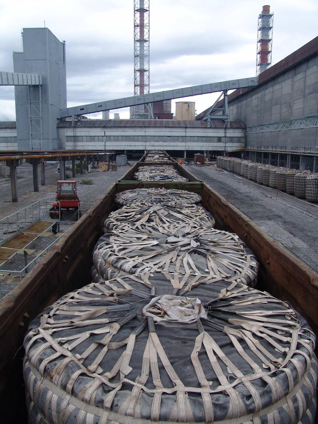
6 1 ( ) - / FLEXIBLE CONTAINER (FC) CHARACTERISTICS AND OPERATION CONDITIONS / º +60º, : Specialized flexible containers FC are intended for transportation of all types of friable products by all kind of transport at an ambient temperature from - 50º up to +60º, and also time storage on platforms of accumulation of cargoes and under warehouse conditions. FC overall dimensions: ±50 ; - diameter 2400±50 mm; ±50 ; - height 2500±50 mm; - 70 ; - empty container mass - not more than 70 kg; - ( ) cargo capacity (net) - not more than kg ,,, -, - - ( ) -.., -, 6: :1 ( 6- ), - ( ) , -, , Container FC consists of the shell made by a dense polyester fabric rubberized from both sides, and a frame grid made by polyester tapes. Their forced joints are sewed by polyester (lavsan) threads. All kinds of a load are supported by a frame grid only. The container structure, used materials, durability of sewing strings and type of a seam should provide factor of safety not less 6:1 at quintuple or sextuple usage at carrying capacity of 14 tons and 8:1 - at multiple usage (more than sextuple), that should proved by true tests (see item ). Operation should be carried out in accordance with the Operation Manual 26469OM, and also Rules of cargoes transportation by rail, technical regulations on accommodation and securing of cargoes in railcars and containers of Ministry of Railways of Russia , :10 3
7 2 / GROUNDING OF CALCULATED SCHEMES AND METODS / 2.1, / SYMBOLS, UNITS NOTATION CONCEPTIONS / 1 Table 1 BC, Blocking force, kn FB, Actual blocking force, kn FR, Lashing device supporting force, kn FT - Pretension force, kn Fx,, Longitudinal force acting on a cargo, kn Fy,, Transverse force acting on a cargo, kn Fz, Vertical force acting on a cargo, kn FF, Friction force, kn FFM - Fz, Friction force as a result of vertical force Fz action, kn FR - FR, Friction force as a result of supporting force FR action, kn FFT FT, Friction force as a result of pretension force FT action, kn LC, Lashing force, kn S TF -, Standard pretension force, kn a, 2 Acceleration, m/s 2 b, Vertical moment arm, m c Acceleration coefficient d, Tipping moment arm, m h, Lashing forces moment arm, m g g = 9, Gravity acceleration g = 9, m/s 2 k Reduction factor m, (1000 ) Cargo mass, t (1000 kg) n Lashings number w Breadth of the cargo, Vertical angle, deg - Horizontal angle in longitudinal direc- x, y -, s Sliding friction coefficient D Dynamic friction coefficient tion, deg Horizontal angle in transverse direction, deg 1409:10 4
8 2.2 / ACCELERATION PARAMETERS / 2, 3 4 -, - [1]. IMO/OLP/UN/EWG (CTUs),, - D., -, -,. -, EN C x, C y, C z C x,c y,c z - 3. C x,c y,c z - 4. Maximum acceleration coefficients values are given in tables 2, 3 and 4. They should be taken into account when the cargo is loaded on a transport device for corresponding type of transportation [1]. Above values correspond to IMO/OLP/UN/EWG cargo transport requirements (CTUs). But we create more safe transport conditions inserting D coefficient. Dynamic loads and impacts acting on a cargo during short time period are compensated due to lashing device elasticity and car and trailer impact damping system. Since load value is increased slightly, it is neglected in case if EN Standard requirements are satisfied. Acceleration coefficients C x, C y, C z are given in table 2 in case of road transportation. Acceleration coefficients C x,c y,c z are given in table 3 in case of rail transportation. Acceleration coefficients C x,c y,c z are given in table 4 in case of sea transportation. / Lashing direction / Acceleration coefficients / longitudinal y / transverse / forwarward / back- / Sliding / Tipping / 0,8 0, ,0 longitudinal / transverse - - 0,5 0,5+0,2 b 1,0 a IMO=1,0 s / instead of IMO=1,0 for s b +0,2 / for unstable cargoes only 2 Table 2 z - - / downward vertically 1409:10 5
9 / Lashing direction / longitudinal / transverse 3 Table 3 / Acceleration coefficients / longitudinal y - / transverse z - - / minimal value downward vertically / Sliding / Sliding / Tipping / Tipping 0,6 1,0-1,0 1, ,5 1,0 0,7 / Sea Area / Direction 4 Table 4 / Acceleration coefficients / longitudinal y / transverse / longitudinal 0,3-0,5 / transverse - 0,5 1,0 / longitudinal 0,3-0,3 / transverse - 0,7 1,0 / longitudinal 0,4-0,2 / transverse - 0,8 1,0.. IMO / NOTES. See IMO instructions / Baltic Sea / / North Sea south area / Mediterranean Sea / unlimited z - - / minimal value downward vertically 1409:10 6
10 3 / LASHING DEVICE CHARACTERISTICS CALCULATION METHOD/ 3.1 / GENERAL /,, [1] ( -, -,, ) [1] , [1] , -,, , - ; -,, [1] STF,, ,, - -. Following notations, symbols, units, and abbreviations are used hereinafter Cargo securing equipment Systems and equipments for safety loading [1] Lashing device Flexible device for loading of the cargo on vehicle Pretension device Mechanical device for lashing device pretension and holding (for example, sliding ratchet coupling, winch, tension hand grip) [1] Pretension indicator Device indicated lashing device force due to tension elements during vehicle movement or when loading area is deformated [1] Attachment point Cargo fixed part, for example transport ring for loading safeguarding device attaching Lashing point The fixing device on a vehicle used for cargo lashing device direct joint. It looks as a ring, a hook, eye or the fixing bus Standard pretension force STF Residual force arisen, when tension lever becomes free Cargo transverse lashing method Method of lashing when friction force arisen due additional vertical components regarding cargo weight 1409:10 7
11 3.1.9, Cargo direct lashing method Method of lashing when lashing device joints to fixed part of the cargo or to specified lashing points. 3.2 / DEFINITION OF CALCULATED PARAMETERS / m, a C, g, a = C g Fx, -, ( ) (Fx = m cx g) , - Fy, - (y- ) (Fy = m Cy g) Fz, (z- ) - (Fz= m cz g) s D -,, FF, -, Cargo mass m Lashed mass Cargo acceleration a Maximum acceleration for a given kind of transportation Acceleration coefficient C It should be multiplied on gravity acceleration g to obtain cargo acceleration a = C g for a given type of transport Longitudinal force acting on the cargo Fx Inertia force acting on the cargo (Fx = m Cx g) along (x-axis) due to vehicle movement Transverse force acting on the cargo Fy Inertia force acting on the cargo (Fy = m Cy g) along (y-axis) due to vehicle movement Vertical force acting on the cargo Fz Total sum of vertical forces (Fz= m Cz g) determined by cargo weight force and inertia force acting on a cargo along vehicle vertical axis (z-axis) Sliding friction coefficient s Coefficient of friction between cargo and contact area Dynamic friction coefficient D Coefficient of friction between moving cargo and contact area Friction force FF The force acting in opposite to cargo movement direction due to friction between cargo 1409:10 8
12 , FB, BC, n FT, k, FR, LC, , x - (x- ) y - (y- ) and loading area surface Actual blocking force FB The force acting on blocking device in specified direction Blocking force BC Maximal force determined blocking device bearing strength in specified direction Number n Number of lashings Pretension force of the lashing device FT Lashing device force due to tensioning device acting Factor k Factor takes into account pretension force reduction due to friction between cargo and lashings Lashing device supporting force FR The force acting on lashing device when vehicle moving Lashing force LC The lashing device maximal force under direct tensioning condition Vertical angle The angle between lashing device and attached vehicle surface Horizontal angle in longitudinal direction x The angle between lashing device and vehicle longitudinal axis (x-axis) measured in loading area plane Horizontal angle in transverse direction y The angle between lashing device and vehicle transverse axis (y-axis) measured in loading area plane. : Following equilibrium conditions should be complied to provide main requirements of the FC safety transportation: 1409:10 9
13 - - ; resultant vector of all forces acting on a cargo should be equal zero; - resultant vector of all force moments acting on a cargo should be equal zero. EN , EN EN , -, -, -. Lashing belts according to EN , chains according to EN and wire ropes according to EN should withstand forces and moments acting on a FC in longitudinal, transverse and vertical directions during transportation. -,,, -, -., -,,,, -.,. In general case should be done to provide cargo equilibrium using anchor bolts, blocking devices and/or locking devices. Lashing by anchor bolts with full geometrical closure is applied to container transportation mainly and not combined with other lashings. Blocking devices often used together with other lashings. : There are two types of lashing -, -,,, ; - -,, -,. - transverse cargo lashing when cargo holds due to force acting on cargo bearing area vertically downward; - direct cargo lashing with vehicle body by tensioning belts. Thus some small cargo shiftings are permitted. They are determined by lashing devices elasticity and values of forces acting on a cargo. 1409:
 and transverse (along y-axis) Stability conditions are written by following manner")
14 4 / CALCULATION OF THE STABILITY OF NON-LASHING CARGO / - ( ), ( y). 1, - : Stability assessment of a non-lashed cargo should be done in both directions: longitudinal (along x-axis) and transverse (along y-axis) Stability conditions are written by following manner using designations defined on figure 1: Fx, y cx, y Fz bx, y Fx, yd ; bx, y d ; bx y d F c z, (1) z C x, C y, C z.. 2, 3, 4. (1), -. Values C x, C y, C z are acceleration coefficients values (see tables 2, 3 and 4). Cargo is considered as stable if conditions (1) are satisfied. : 1 - ; 2 ; 3 - Symbols: 1 - centre of gravity; 2 cargo; 3 - tipping axis.1 Fig. 1 Non-lashed cargo on a bearing area. 1409:
15 4.1 / BLOCKING DEVICE / - : Equilibrium condition in longitudinal and transverse directions: F B FF Fx, y ; FB Dmczg mcx, yg ; F ( c, c mg (2) B x y D z ) (.. 2): BC ( c, Blocking force is calculated by following formulae (see also fig. 2) c mg, (3) x y D z) : Where: m - ; m mass of the cargo; g - ; g - gravity acceleration; D -. D - dynamic friction coefficient.,, -,. Blocking device installed to non-lashed cargo fixing should be used in case of stable cargo only. : 1 - ; 2 ; 3 - Symbols: 1 - centre of gravity; 2 cargo; 3 - blocking device. 2 Fig. 2 Cargo lashing by the blocking device 4.2 / TRANSVERSE LASHING OF THE CARGO /, -. 3, - -, -, Sliding prevention In case of transverse cargo lashing, as shown on fig. 3, lashing device is stretched pretension force F T. Thus friction force between cargo and contact surface is increased and sliding of the cargo is prevented. 1409:
16 : 1 ; 2 ; 3 ; 4 - ; 5 ; 6 ; 7 ; 8. Symbols: 1 cargo; 2 vertical axis; 3 lashing device; 4 tensioning device; 5 transverse axis; 6 lashing point; 7 horizontal surface; 8 longitudinal axis. : F FM FFT Fx, y. 3 Fig. 3 Cargo transverse lashing Forces equilibrium condition is described by following manner: ; ( mc g nkf sin ) mc g (4) : nk sin F ( c, c mg ; D T x y D z ) - : n D z T x, y D Pretension force is determined by following formulae: ( cx, y Dcz ) mg. (5) nk sin 1409: F ( c, c ) mg T D Required lashings number is determined by following formulae: x y D z ; (6) k sin F -. where is a vertical angle. : 0,1LC FT 0, 5LC T Any lashing device pretension force value is limited by the following range:
17 -, - (4) (5) - : BC nk F (..4) h w, - n, -,. - (b, d)., : nf T If in case of transverse cargo lashing blocking devices are used, equations (4) and (5) are led to following relationship: sin ( c, c mg ; (7) D T x y D z) Tipping and sliding prevention Fixed block (see fig. 4) with height h and width w is lashed on cargo loading area by transverse lashings. Lashings number is n. Centre gravity of the block coincides with block geometry centre (b, d). Tipping prevention condition as a result of cargo equilibrium conditions is following: 1 Fx, yh Fzw, (8) 2 ( k 1) wsin (2 k) h cos Fx, y mcx, yg, F mc g where F mc x, y x, yg, F mc g F T : nf. z T z z Lower threshold of the force F T from the cargo tipping prevention point of view is calculated by following formulae: 1 mg( cx, yh czw), (9) 2 ( k 1) wsin (2 k) hcos Cargo sliding prevention condition may be formulated using formulae above. z : 1 ; 2 ; 3 ; 4. Symbols: 1 tipping axis; 2 pretension indicator; 3 tensioning device; 4 centre of gravity.. 4 Fig. 4 Transverse cargo lashing against tipping and sliding 1409:
18 5 / DIRECT LASHING / -., - : -,, ; -,,. - F R. Supporting forces F R are acting in some lashing devices depending of cargo shifting directions. - : -, - - ; In case of direct lashing cargo is lashed straightly on vehicle. Lashing is considered as direct if following conditions are satisfied: - tilted and diagonal lashings are directly attached to cargo and vehicle body; - ring-like and top-over loop lashings are directly attached to vehicle body only. There are direct cargo lashing of following types: - lashings tilted relative to longitudinal and transverse directions; - (. 5); - diagonal cargo lashing (see fig. 5); - ; - ring-like lashing; -. - lashing by cargo top-over loop. : 1 ; 2 ; 3 ; 4 ; 5 ; 6. Symbols: 1 cargo; 2 lashing device; 3 vertical axis; 4 transverse axis; 5 longitudinal axis; 6 loaded area.. 5 Fig. 5 Cargo diagonal lashing 1409:
19 : 2 ; F Rx, y FFM FFR Fx, y Equilibrium cargo condition is presented by following form in longitudinal and transverse directions: 2cos cos F ( mc g 2sin F mc g ; x. v R D z R ) x. v 2 (cos cos x. v D R x, y z ) sin ) F ( C DC mg, (10) where: m - ; m cargo mass; g - ; g - gravity acceleration; C x, C y C z - ; C x, C y C z - acceleration parameters; D - - [1]; k - 6.2; k according 6.2; - ; - vertical angle; x - - ; y D - dynamic friction coefficient according Addendum B [1]; x - horizontal angle in longitudinal direction; y - horizontal angle in transverse direction. NOTE. Lashing device should be tensioned preliminary by hand. LC - 2 (cos cos x. v D x, y D z ) BC -, -, - : Lashing force LC is calculated by following formulae: sin ) LC ( C C mg (11) Blocking force BC of unstable cargo diagonal lashing is calculated by following formulae taking into account usage of the blocking device in one of specified directions: h d b BC ( Cx, y DCz ) mg (12) h h, d, b.. 1. Dimensions h, d, b see fig / NON-LASHED CARGO FC STABILITY CALCULATION / - (1) Non-lashed cargo stability conditions (1) Fx, y cx, y Fz bx, y Fx, yd ; bx, y d ; bx, y d F c 1409: z z Cargo with mass of kg is considered as homogeneous.
20 b x,y =1,2, d=1,25, F z =149,8 b x,y =1,2 m, d=1,25 m, F z =149,8 kn b x, y (.. 2) - =0,8 ( - ), C =0,5 ( ); C x, y C z Stability condition 1409: d Road transportation standard acceleration coefficients see (Table 2) - longitudinal direction =0,8 (forward), C =0,5 (backward); - C =0,5; - transverse direction C =0,5; - C z =1,0. - vertically downward C z =1,0. - 1,2>0,8*1,25/1,0 = 1,0 longitudinal direction (forward) - 1,2>0,5*1,25/1,0 = 0,625 longitudinal direction (backward) 1,2>0,5*1,25/1,0 = 0,625 transverse direction. Stability conditions are fulfilled. - (.. 3) - =0,6 ( - ), C =1,0( ) - C z =1,0 ( ), C z =1,0 ( ); Rail transportation standard acceleration coefficients (see Table 3) - longitudinal direction =0,6 (tipping), C =1,0 (sliding) - longitudinal direction =0,6 (tipping), C =1,0 (sliding); - C =0,5; - transverse direction C =0,5; - C z =1,0 ( ), C z =0,7 ( ) - - vertically downward C z =1,0 (tipping), C z =0,7 (sliding). Checking of the cargo stability in longitudinal direction 1,2>0,6*1,25/1,0 = 0,75 tipping 1,2<1,0*1,25/1,0=1,25 sliding - Stability checking in transverse direction 1,2>0,5*1,25/1,0=0,625 tipping 1,2>0,5*1,25/0,7=0,89 sliding (..4): Sea transportation standard acceleration coefficients under Mediterranean Sea condition (see Table 4): - =0,4, C z =0,2; - longitudinal direction =0,4, C z =0,2; - C =0,8; C z =1,0. - transverse direction C =0,8; C z =1,0. : - - longitudinal direction Stability checking:
21 1,2<0,4*1,25/0,2 = 2,5- - transverse direction 1,2>0,8*1,25/1,0 = 1, (1) ( ). ( ) (1) ( - ) (1) (, - ) ,2<0,4*1,25/0,2 = 2,5 - stability conditions not satisfied 1,2>0,8*1,25/1,0 = 1,2 - stability conditions are fulfilled. Conclusions 1. Flexible containers FC with homogeneous cargo are stable in all cases during road transportation 2. Flexible containers FC with homogeneous cargo are unstable in longitudinal direction (sliding) in case of rail transportation. Stability condition (1) is not satisfied. Lashings are needed (see item 2.1 of a current paragraph) 3. Flexible containers FC with homogeneous cargo are unstable in longitudinal direction (tipping) in case of rail transportation. Stability condition (1) is fulfilled. 4. Flexible containers FC with homogeneous cargo are stable in transverse direction (sliding and tipping) in case of rail transportation. Stability condition (1) is fulfilled. 5. Flexible containers FC with homogeneous cargo are unstable in longitudinal direction only during sea transportation. 1409:
22 6 - / BLOCKING FORCE CALCULATION IN CASE OF NON-LASHED STABLE CARGO FIXING / - (2): BC ( C, C mg, x y D z) Blocking force for non-lashed cargo is calculated by following formulae (2): D =0,25 ( - [1]) where D =0,25 (Europallets wood [1]) - ( ) =1,0; C z =1,0; =1,0; C z =1,0; - for rail transport (sliding in longitudinal direction) BC=(1,0-0,25*1,0)*14=10,5 BC=(1,0-0,25*1,0)*14=10,5 kn - ( - ) =0,4; C z =0,2; =0,4; C z =0,2; - for sea transport (longitudinal direction) BC=(0,4-0,20*1,0)*14=2,8 BC=(0,4-0,20*1,0)*14=2,8 kn 1409:
23 / FC TRANSVERSE LASHING CALCULATION IN CASE OF ROAD TRANSPORTATION / 1409:
24 2,5 Trailer pad width 2,5 m : Cargo in FC m = 14 Mass m = 14t : 2,4 Width 2,4 m : 2,5 Height 2,5 m : 2,4 Length 2,4 m : Lashing device: LC = 30, STF = 6,25 kn = 625 dan, k = 1,5 [1]. (6) n ( Cx, y D T Lashing force LC = 30 kn, STF = 6,25 kn = 625 dan DCz) mg (0,8 0,3 1) 14 1,05, k sin F 1,5 0,3 0, where 0,1LC FT 0, 5LC -. :,, Each lashing device is supplied by tensioning device and pretension indicator, thus reduction coefficient is equal k = 1,5 [1]. Required lashings number is determined by formulae (6) 0,1LC FT 0, 5LC - pretension force. Friction: Cargo in FC, load pad material - D = 0,3 (c. [1]). friction coefficient D = 0,3 (see [1]). : = 80º Vertical angle = 80º - (.. 2): - : C x = 0,8 C x = 0,8. : C z = 1,0 C z = 1,0.. - F T n = 2, - LC = 30kN = 3000 dan. - (7) - F T - Acceleration coefficients in case of road transportation (see Table 2): Longitudinal acceleration coefficient: Vertical acceleration coefficient: Conclusion. Required lashings number in case of transverse cargo lashing and maximal force F T value n = 2. Each lashing device should withstand lashing force LC = 30kN = 3000 dan. Blocking force is calculated by following formulae (7) Required blocking force in case of minimal pretension force value F T is determined by following manner: 1409:
25 BC nk sin F ( C, C mg, D T x y D z ) = (0,8-0,3)*14-1,5*0,3*0,985*3=5, n=1, - =5,67. Thus = (0,8-0,3)*14-1,5*0,3*0,985*3=5,67 kn. Conclusion. Required lashings number in case of minimal pretension force value n = 1. Blocking force is =5,67 kn. 1409:
26 8 / FC DIAGONAL LASHING CALCULATION IN CASE OF SEA TRANSPORTATION /, -, - x y - (.. 5). -,,, 8, 4 -. Two pairs lashing devices are used in case of diagonal cargo lashing. They are arranged with different angles because, besides vertical angle, two angles in a horizontal plane are occurred - x in longitudinal direction and y in transverse direction (see fig. 5). Thus only 4 lashings are need. In case of other lashing tipe 8 lashings are need. (11),(12). Calculations are performed by formulae (11), (12). LC - : 2, (cos cos x. v D sin ) LC ( cx y Dcz ) mg =0º - -, x,y = 45º , C x = 0,4 (.4), C z = 0,2 ( - ), C y = 0,8 (.4), C z = 1,0 ( - ), Lashing force LC is calculated by following formulae:, D = 0,3 (c. [1]). D = 0,3 (see [1]). ( cx, y Dcz) mg LC ; 2(cos cos sin ) ( ) 10-14,, x. v LC 0,5 (0,8 0,3) 14 / 2 5 =0º when lashing devices are paralleled to load pad plane; x,y = 45º in case of FC symmetrical lashing; C x = 0,4 (see Table 4), C z = 0,2 (longitudinal direction); C y = 0,8 (Table 4), C z = 1,0 (transverse direction) 1409: D LC5 5LC 25 Lashing force (transverse direction) of a single FC10-14, kn Total lashing force of a block of five FC, kn 12 Hold s load pad width is 12 m. : Cargo in FC: m = 14 Mass m=14t. : 2,4 Width 2,4 m. : 2,5 Height 2,5 m. : 2,4 Length 2,4 m.
27 / GENERAL CONCLUSION / 1. - : (1) - ( ) -. ( ) (1) - ( ) (1) - (, ) : 2.1 ) BC=10, ( - ) BC=2, : F T n = 2, - LC = 30kN = 3000 dan. 3.2 n=1, - =5,67 kn. 1. Analysis of cargo stability calculations leads to following conclusions: 1.1 Flexible containers FC with homogeneous cargo are stable in all cases of road transportation. 1.2 Flexible containers FC with homogeneous cargo are unstable in longitudinal direction (sliding) in case of rail transportation. Stability condition (1) is not satisfied. Lashings are needed (see item 2.1 of a current paragraph) 1.3 Flexible containers FC with homogeneous cargo are unstable in longitudinal direction (tipping) in case of rail transportation. Stability condition (1) is fulfilled. 1.4 Flexible containers FC with homogeneous cargo are stable in transverse direction (sliding and tipping) in case of rail transportation. Stability condition (1) is fulfilled. 1.5 Flexible containers FC with homogeneous cargo are unstable in longitudinal direction only in case of sea transportation. 2. Required blocking force calculation for unstable cargo 2.1 BC=10,5 kn during rail transportation (sliding in longitudinal direction). 2.2 BC=2,8 kn during sea transportation (in longitudinal direction). 3. FC transverse lashing calculation during in case of road transportation 3.1 Required lashings number in case of transverse cargo lashing and maximal force FT value n = 2 during road transportation. Each lashing device should withstand lashing force LC = 30kN = 3000 dan. 3.2 Required lashings number in case of minimal pretension force value n = 1. Blocking force is =5,67 kn. 1409:
28 -, - [1] , LC 5 =LC*n =25. Polyester bands providing standard safety margin [1] are recommended as lashing devices. 4. FC diagonal lashing calculation in case of sea transportation 4.1 Diagonal lashings of each of 5 FC should be installed at 2,5 m above load pad plane in orthogonal directions. 4.2 Total lashing force of FC block consisting of 5 FC LC 5 =LC*n = , - [1]. Lashing chains with appropriate diameter providing standard safety margin [1] are recommended as lashing devices. / USED TECHNICAL DOCUMENTATION / 1. EN : European Standard. EN :2003. European Committee for Standardization. 2. European Best Practice Guidelines on Cargo Securing for Road Transport. European Commission. Directorate-General for Energy and Transport. 1409:
Cargo securing in Sweden
 State of play on national saf fe loading & cargo securing standards in Europe and wor rk of the UN group of experts on the ILO/IMO/U UNECE standard Slagelse, Denmark 6-7 Septem mber 2012 Sven Sökjer-Petersen
CARGO STOWAGE AND SECURING
 Resolutions from the 17th Session of the Assembly of IMO, November 1991, as amended CODE OF SAFE PRACTICE FOR CARGO STOWAGE AND SECURING CARGO STOWAGE AND SECURING ANNEX 13. Til bruk i maritime fagskoler
1N the force that a 100g bar of chocolate exerts on your hand.
 Forces: - - > cause change in motions Newton's first law = law of inertia In absence of a net external force acting upon it, a body will either remain at rest or continue in its rectilinear uniform motion.
Equilibrium of a Particle
 ME 108 - Statics Equilibrium of a Particle Chapter 3 Applications For a spool of given weight, what are the forces in cables AB and AC? Applications For a given weight of the lights, what are the forces
two structural analysis (statics & mechanics) APPLIED ACHITECTURAL STRUCTURES: DR. ANNE NICHOLS SPRING 2017 lecture STRUCTURAL ANALYSIS AND SYSTEMS
 APPLIED ACHITECTURAL STRUCTURES: DR. ANNE NICHOLS SPRING 2017 lecture STRUCTURAL ANALYSIS AND SYSTEMS") APPLIED ACHITECTURAL STRUCTURES: STRUCTURAL ANALYSIS AND SYSTEMS DR. ANNE NICHOLS SPRING 2017 lecture two structural analysis (statics & mechanics) Analysis 1 Structural Requirements strength serviceability
APPLIED ACHITECTURAL STRUCTURES: STRUCTURAL ANALYSIS AND SYSTEMS DR. ANNE NICHOLS SPRING 2017 lecture two structural analysis (statics & mechanics) Analysis 1 Structural Requirements strength serviceability
Installation instructions, accessories. Snow chains
 Instruction No 30664147 Version 1.0 Part. No. Snow chains R7700468 страница 1 / 15 Equipment A0000162 R7700458 страница 2 / 15 R7700448 страница 3 / 15 INTRODUCTION Read through all of the instructions
Inclined plane with protractor and pulley, roller, weight box, spring balance, spirit level, pan and thread.
 To find the downward force, along an inclined plane, acting on a roller due to gravity and study its relationship with the angle of inclination by plotting graph between force and sin θ. Inclined plane
Section 1 Changes in Motion. Chapter 4. Preview. Objectives Force Force Diagrams
 Section 1 Changes in Motion Preview Objectives Force Force Diagrams Section 1 Changes in Motion Objectives Describe how force affects the motion of an object. Interpret and construct free body diagrams.
Introduction to Geohazard Standard Specification for Simple Drapery
 Introduction to Geohazard Standard Specification for Simple Drapery Up to now, there is no standard specification for geohazard solutions in North America. Often projects specifications are referring to
Summary document for the catalogue of questions "Chemicals" Transmitted by the Central Commission for the Navigation of the Rhine
 Economic Commission for Europe INF.14 Inland Transport Committee Working Party on the Transport of Dangerous Goods Joint Meeting of Experts on the Regulations annexed to the European Agreement concerning
Chapter 5 Force and Motion
 Chapter 5 Force and Motion Chapter Goal: To establish a connection between force and motion. Slide 5-2 Chapter 5 Preview Slide 5-3 Chapter 5 Preview Slide 5-4 Chapter 5 Preview Slide 5-5 Chapter 5 Preview
 www.onlineexamhelp.com www.onlineexamhelp.com *5840741268* UNIVERSITY OF CAMBRIDGE INTERNATIONAL EXAMINATIONS General Certificate of Education Advanced Level FURTHER MATHEMATICS 9231/02 Paper 2 October/November
FORCE. Definition: Combining Forces (Resultant Force)
") 1 FORCE Definition: A force is either push or pull. A Force is a vector quantity that means it has magnitude and direction. Force is measured in a unit called Newtons (N). Some examples of forces are:
1 FORCE Definition: A force is either push or pull. A Force is a vector quantity that means it has magnitude and direction. Force is measured in a unit called Newtons (N). Some examples of forces are:
4.0 m s 2. 2 A submarine descends vertically at constant velocity. The three forces acting on the submarine are viscous drag, upthrust and weight.
 1 1 wooden block of mass 0.60 kg is on a rough horizontal surface. force of 12 N is applied to the block and it accelerates at 4.0 m s 2. wooden block 4.0 m s 2 12 N hat is the magnitude of the frictional
Section /07/2013. PHY131H1F University of Toronto Class 9 Preclass Video by Jason Harlow. Based on Knight 3 rd edition Ch. 5, pgs.
 PHY131H1F University of Toronto Class 9 Preclass Video by Jason Harlow Based on Knight 3 rd edition Ch. 5, pgs. 116-133 Section 5.1 A force is a push or a pull What is a force? What is a force? A force
KINGS COLLEGE OF ENGINEERING ENGINEERING MECHANICS QUESTION BANK UNIT I - PART-A
 KINGS COLLEGE OF ENGINEERING ENGINEERING MECHANICS QUESTION BANK Sub. Code: CE1151 Sub. Name: Engg. Mechanics UNIT I - PART-A Sem / Year II / I 1.Distinguish the following system of forces with a suitable
What is a Force? Free-Body diagrams. Contact vs. At-a-Distance 11/28/2016. Forces and Newton s Laws of Motion
 Forces and Newton s Laws of Motion What is a Force? In generic terms: a force is a push or a pull exerted on an object that could cause one of the following to occur: A linear acceleration of the object
THE NEW 1.1 MN m TORQUE STANDARD MACHINE OF THE PTB BRAUNSCHWEIG/GERMANY
 THE NEW 1.1 MN m TORQUE STANDARD MACHINE OF THE PTB BRAUNSCHWEIG/GERMANY D. Peschel 1, D. Mauersberger 1, D. Schwind 2, U. Kolwinski 2 1 Solid mechanics department, PTB, Germany 2 Gassmann Theiss Messtechnik
SOLUTION 8 7. To hold lever: a+ M O = 0; F B (0.15) - 5 = 0; F B = N. Require = N N B = N 0.3. Lever,
 - 5 = 0; F B = N. Require = N N B = N 0.3. Lever,") 8 3. If the coefficient of static friction at is m s = 0.4 and the collar at is smooth so it only exerts a horizontal force on the pipe, determine the minimum distance x so that the bracket can support
8 3. If the coefficient of static friction at is m s = 0.4 and the collar at is smooth so it only exerts a horizontal force on the pipe, determine the minimum distance x so that the bracket can support
REVISING MECHANICS (LIVE) 30 JUNE 2015 Exam Questions
 30 JUNE 2015 Exam Questions") REVISING MECHANICS (LIVE) 30 JUNE 2015 Exam Questions Question 1 (Adapted from DBE November 2014, Question 2) Two blocks of masses 20 kg and 5 kg respectively are connected by a light inextensible string,
REVISING MECHANICS (LIVE) 30 JUNE 2015 Exam Questions Question 1 (Adapted from DBE November 2014, Question 2) Two blocks of masses 20 kg and 5 kg respectively are connected by a light inextensible string,
The Laws of Motion. Newton s first law Force Mass Newton s second law Gravitational Force Newton s third law Examples
 The Laws of Motion Newton s first law Force Mass Newton s second law Gravitational Force Newton s third law Examples Gravitational Force Gravitational force is a vector Expressed by Newton s Law of Universal
d. Determine the power output of the boy required to sustain this velocity.
 AP Physics C Dynamics Free Response Problems 1. A 45 kg boy stands on 30 kg platform suspended by a rope passing over a stationary pulley that is free to rotate. The other end of the rope is held by the
Vector Mechanics: Statics
 PDHOnline Course G492 (4 PDH) Vector Mechanics: Statics Mark A. Strain, P.E. 2014 PDH Online PDH Center 5272 Meadow Estates Drive Fairfax, VA 22030-6658 Phone & Fax: 703-988-0088 www.pdhonline.org www.pdhcenter.com
CHAPTER 2: FORCES AND MOTION
 CHAPTER 2: FORCES AND MOTION 2.1 Linear Motion Linear Motion is motion in a straight line with constant acceleration. Classification Scalar Vector Physical quantity with Magnitude only Magnitude and direction
Physics 2211 A & B Quiz #3 Solutions Fall 2016
 Physics 2211 A & B Quiz #3 Solutions Fall 2016 I. (16 points) A block of mass m 1 is connected by an ideal rope passing over an ideal pulley to a block of mass m 2. The block of mass m 1 slides up a plane
SOLUTION 8 1. a+ M B = 0; N A = 0. N A = kn = 16.5 kn. Ans. + c F y = 0; N B = 0
 8 1. The mine car and its contents have a total mass of 6 Mg and a center of gravity at G. If the coefficient of static friction between the wheels and the tracks is m s = 0.4 when the wheels are locked,
Jurong Junior College 2014 J1 H1 Physics (8866) Tutorial 3: Forces (Solutions)
 Tutorial 3: Forces (Solutions)") Jurong Junior College 2014 J1 H1 Physics (8866) Tutorial 3: Forces (Solutions) Take g = 9.81 m s -2, P atm = 1.0 x 10 5 Pa unless otherwise stated Learning Outcomes (a) Sub-Topic recall and apply Hooke
Jurong Junior College 2014 J1 H1 Physics (8866) Tutorial 3: Forces (Solutions) Take g = 9.81 m s -2, P atm = 1.0 x 10 5 Pa unless otherwise stated Learning Outcomes (a) Sub-Topic recall and apply Hooke
2D - STRIP ANCHOR LIFTING SYSTEM
 2D - STRIP ANCHOR LIFTING SYSTEM WWW.TERWA.COM Terwa reserves the right to make changes to the documentation at any time Page 1 OVERVIEW LIFTING CLUTCHES AND TRANSPORT ANCHOR SA-B SA-ST SA-TTU UNIVERSAL
Physics, Chapter 3: The Equilibrium of a Particle
 University of Nebraska - Lincoln DigitalCommons@University of Nebraska - Lincoln Robert Katz Publications Research Papers in Physics and Astronomy 1-1958 Physics, Chapter 3: The Equilibrium of a Particle
PHYSICS. Chapter 5 Lecture FOR SCIENTISTS AND ENGINEERS A STRATEGIC APPROACH 4/E RANDALL D. KNIGHT Pearson Education, Inc.
 PHYSICS FOR SCIENTISTS AND ENGINEERS A STRATEGIC APPROACH 4/E Chapter 5 Lecture RANDALL D. KNIGHT Chapter 5 Force and Motion IN THIS CHAPTER, you will learn about the connection between force and motion.
Fraser Heights Secondary Physics 11 Mr. Wu Practice Test (Dynamics)
") Fraser Heights Secondary Physics 11 Mr. Wu Practice Test (Dynamics) Instructions: Pick the best answer available for Part A. Show all your work for each question in Part B Part A: Multiple-Choice 1. Inertia
Fraser Heights Secondary Physics 11 Mr. Wu Practice Test (Dynamics) Instructions: Pick the best answer available for Part A. Show all your work for each question in Part B Part A: Multiple-Choice 1. Inertia
Time: 1 hour 30 minutes
 Paper Reference(s) 6677/01 Edexcel GCE Mechanics Gold Level G1 Time: 1 hour 30 minutes Materials required for examination Mathematical Formulae (Green) Items included with question papers Nil Candidates
Application nr. 7 (Connections) Strength of bolted connections to EN (Eurocode 3, Part 1.8)
 Strength of bolted connections to EN (Eurocode 3, Part 1.8)") Application nr. 7 (Connections) Strength of bolted connections to EN 1993-1-8 (Eurocode 3, Part 1.8) PART 1: Bolted shear connection (Category A bearing type, to EN1993-1-8) Structural element Tension
Application nr. 7 (Connections) Strength of bolted connections to EN 1993-1-8 (Eurocode 3, Part 1.8) PART 1: Bolted shear connection (Category A bearing type, to EN1993-1-8) Structural element Tension
Code No: R Set No. 1
 Code No: R05010302 Set No. 1 I B.Tech Supplimentary Examinations, February 2008 ENGINEERING MECHANICS ( Common to Mechanical Engineering, Mechatronics, Metallurgy & Material Technology, Production Engineering,
LIQUID ACCELEROMETER P3-3525
 WWW.ARBORSCI.COM LIQUID ACCELEROMETER P3-3525 BACKGROUND: The Liquid Accelerometer is intended to illustrate accelerations in various dynamic situations. The device is a clear rectangular container partially
Engineering Mechanics: Statics in SI Units, 12e
 Engineering Mechanics: Statics in SI Units, 12e 5 Equilibrium of a Rigid Body Chapter Objectives Develop the equations of equilibrium for a rigid body Concept of the free-body diagram for a rigid body
Chapter 4. Answer Key. Physics Lab Sample Data. Mini Lab Worksheet. Tug-of-War Challenge. b. Since the rocket takes off from the ground, d i
 Chapter 3 continued b. Since the rocket takes off from the ground, d i 0.0 m, and at its highest point, v f 0.0 m/s. v f v i a t f (d f d i ) 0 v i a t f d f v i d f a t f (450 m/s) ( 9.80 m/s )(4.6 s)
MEI Mechanics 1. Applying Newton s second law along a line
 MEI Mechanics 1 Applying Newton s second law along a line Chapter assessment 1. (a) The following two questions are about the motion of a car of mass 1500 kg, travelling along a straight, horizontal road.
QUAKE BRAKE TM MODEL QBC-12 SEISMIC SWAY BRACING KIT FEATURING
 QUAKE BRAKE TM MODEL QBC-12 SEISMIC SWAY BRACING KIT FEATURING The QUAKE BRAKE TM Seismic Dampening Device. The QUAKE BRAKE TM was Certified NEBS Level 3 Zone Compliant after being tested in accordance
The Concept of Force Newton s First Law and Inertial Frames Mass Newton s Second Law The Gravitational Force and Weight Newton s Third Law Analysis
 The Laws of Motion The Concept of Force Newton s First Law and Inertial Frames Mass Newton s Second Law The Gravitational Force and Weight Newton s Third Law Analysis Models using Newton s Second Law Forces
Paper Reference. Mechanics M1 Advanced/Advanced Subsidiary. Friday 15 January 2010 Afternoon Time: 1 hour 30 minutes
 Centre No. Candidate No. Paper Reference 6 6 7 7 0 1 Paper Reference(s) 6677/01 Edexcel GCE Mechanics M1 Advanced/Advanced Subsidiary Friday 15 January 2010 Afternoon Time: 1 hour 30 minutes Surname Signature
Rock slope rock wedge stability
 Engineering manual No. 28 Updated: 02/2018 Rock slope rock wedge stability Program: Rock stability File: Demo_manual_28.gsk The aim of the chapter of this engineering manual is to explain a rock slope
Ground Rules. PC1221 Fundamentals of Physics I. Force. Zero Net Force. Lectures 9 and 10 The Laws of Motion. A/Prof Tay Seng Chuan
 PC1221 Fundamentals of Physics I Lectures 9 and 10 The Laws of Motion A/Prof Tay Seng Chuan 1 Ground Rules Switch off your handphone and pager Switch off your laptop computer and keep it No talking while
STATICS. FE Review. Statics, Fourteenth Edition R.C. Hibbeler. Copyright 2016 by Pearson Education, Inc. All rights reserved.
 STATICS FE Review 1. Resultants of force systems VECTOR OPERATIONS (Section 2.2) Scalar Multiplication and Division VECTOR ADDITION USING EITHER THE PARALLELOGRAM LAW OR TRIANGLE Parallelogram Law: Triangle
Vane Type Rotary Actuators Series Variations
 Vane Type Rotary Actuators Series Variations Vane Type Exterior CRB Series 0,, 0,, CRBU Series 0,, 0,, CRB Series, 6, 80, Has a compact body with exterior dimensions that do not change regardless of the
Chapter 4. Table of Contents. Section 1 Changes in Motion. Section 2 Newton's First Law. Section 3 Newton's Second and Third Laws
 Forces and the Laws of Motion Table of Contents Section 1 Changes in Motion Section 2 Newton's First Law Section 3 Newton's Second and Third Laws Section 4 Everyday Forces Section 1 Changes in Motion Objectives
Experiment Instructions. Deformation of Frames
 Experiment Instructions SE 0.20 Deformation of Frames Experiment Instructions This manual must be kept by the unit. Before operating the unit: - Read this manual. - All participants must be instructed
Linear guide drives. Synchronous shafts The use of synchronous shafts enables several linear axes to be operated with one drive.
 Linear guide drives Drive concept The linear guides are driven via the hollow shaft in the drive head. The drive head is used to directly install a motor or alternatively (in connection with a center shaft)
Paper Reference R. Mechanics M1 Advanced/Advanced Subsidiary. Friday 6 June 2014 Afternoon Time: 1 hour 30 minutes
 Centre No. Candidate No. Paper Reference(s) 6677/01R Edexcel GCE Mechanics M1 Advanced/Advanced Subsidiary Friday 6 June 2014 Afternoon Time: 1 hour 30 minutes Materials required for examination Mathematical
The box is pushed by a force of magnitude 100 N which acts at an angle of 30 with the floor, as shown in the diagram above.
 1. A small box is pushed along a floor. The floor is modelled as a rough horizontal plane and the 1 box is modelled as a particle. The coefficient of friction between the box and the floor is. 2 The box
VALLIAMMAI ENGINEERING COLLEGE SRM NAGAR, KATTANKULATHUR DEPARTMENT OF MECHANICAL ENGINEERING
 VALLIAMMAI ENGINEERING COLLEGE SRM NAGAR, KATTANKULATHUR 603203 DEPARTMENT OF MECHANICAL ENGINEERING BRANCH: MECHANICAL YEAR / SEMESTER: I / II UNIT 1 PART- A 1. State Newton's three laws of motion? 2.
Chapter 6: Structural Analysis
 Chapter 6: Structural Analysis Chapter Objectives To show how to determine the forces in the members of a truss using the method of joints and the method of sections. To analyze the forces acting on the
Statics Chapter II Fall 2018 Exercises Corresponding to Sections 2.1, 2.2, and 2.3
 Statics Chapter II Fall 2018 Exercises Corresponding to Sections 2.1, 2.2, and 2.3 2 3 Determine the magnitude of the resultant force FR = F1 + F2 and its direction, measured counterclockwise from the
Chapter 12 Static Equilibrium
 Chapter Static Equilibrium. Analysis Model: Rigid Body in Equilibrium. More on the Center of Gravity. Examples of Rigid Objects in Static Equilibrium CHAPTER : STATIC EQUILIBRIUM AND ELASTICITY.) The Conditions
Advanced/Advanced Subsidiary
 Paper Reference(s) 6677 Edexcel GCE Mechanics M1 Advanced/Advanced Subsidiary Monday 12 January 2004 Afternoon Time: 1 hour 30 minutes Materials required for examination Answer Book (AB16) Mathematical
Newton s 3 Laws of Motion
 Newton s 3 Laws of Motion 1. If F = 0 No change in motion 2. = ma Change in motion Fnet 3. F = F 1 on 2 2 on 1 Newton s First Law (Law of Inertia) An object will remain at rest or in a constant state of
Contents. Concept Map
 Contents 1. General Notes on Forces 2. Effects of Forces on Motion 3. Effects of Forces on Shape 4. The Turning Effect of Forces 5. The Centre of Gravity and Stability Concept Map April 2000 Forces - 1
Product description. Compact Modules. Characteristic features. Further highlights
 4 Compact Modules Product description Characteristic features Five fine-tuned sizes based on a compact precision aluminum profile with two integrated pre-tensioned ball rail systems Identical external
PHYSICS 231 Laws of motion PHY 231
 PHYSICS 231 Laws of motion 1 Newton s Laws First Law: If the net force exerted on an object is zero the object continues in its original state of motion; if it was at rest, it remains at rest. If it was
Paper Reference. Paper Reference(s) 6677/01 Edexcel GCE Mechanics M1 Advanced/Advanced Subsidiary
 6677/01 Edexcel GCE Mechanics M1 Advanced/Advanced Subsidiary") Centre No. Candidate No. Paper Reference 6 6 7 7 0 1 Paper Reference(s) 6677/01 Edexcel GCE Mechanics M1 Advanced/Advanced Subsidiary Friday 11 January 2008 Morning Time: 1 hour 30 minutes Materials required
Centre No. Candidate No. Paper Reference 6 6 7 7 0 1 Paper Reference(s) 6677/01 Edexcel GCE Mechanics M1 Advanced/Advanced Subsidiary Friday 11 January 2008 Morning Time: 1 hour 30 minutes Materials required
ME 230 Kinematics and Dynamics
 ME 230 Kinematics and Dynamics Wei-Chih Wang Department of Mechanical Engineering University of Washington Lecture 8 Kinetics of a particle: Work and Energy (Chapter 14) - 14.1-14.3 W. Wang 2 Kinetics
Special edition paper
 Development of New Aseismatic Structure Using Escalators Kazunori Sasaki* Atsushi Hayashi* Hajime Yoshida** Toru Masuda* Aseismatic reinforcement work is often carried out in parallel with improvement
Chapter 9 Rotational Dynamics
 Chapter 9 ROTATIONAL DYNAMICS PREVIEW A force acting at a perpendicular distance from a rotation point, such as pushing a doorknob and causing the door to rotate on its hinges, produces a torque. If the
Physics 2211 M Quiz #2 Solutions Summer 2017
 Physics 2211 M Quiz #2 Solutions Summer 2017 I. (16 points) A block with mass m = 10.0 kg is on a plane inclined θ = 30.0 to the horizontal, as shown. A balloon is attached to the block to exert a constant
physicsandmathstutor.com Paper Reference Mechanics M1 Advanced/Advanced Subsidiary Friday 11 January 2008 Morning Time: 1 hour 30 minutes
 Centre No. Candidate No. Paper Reference 6 6 7 7 0 1 Paper Reference(s) 6677/01 Edexcel GCE Mechanics M1 Advanced/Advanced Subsidiary Friday 11 January 2008 Morning Time: 1 hour 30 minutes Materials required
Economic and Social Council
 United Nations Economic and Social Council ECE/TRANS/WP.29/GRE/2017/20 Distr.: General 7 August 2017 Original: English Economic Commission for Europe Inland Transport Committee World Forum for Harmonization
Forces & NEWTON S LAWS HOMEWORK
 1 Forces & NEWTON S LAWS HOMEWORK BASIC CONCEPTS OF MASS VS. WEIGHT VS. VOLUME VS. DENSITY MULTIPLE CHOICE: You have one kilogram of feathers and one kilogram of lead. Which has more: 1. mass? 3. weight?
Tue Sept 15. Dynamics - Newton s Laws of Motion. Forces: Identifying Forces Free-body diagram Affect on Motion
 Tue Sept 15 Assignment 4 Friday Pre-class Thursday Lab - Print, do pre-lab Closed toed shoes Exam Monday Oct 5 7:15-9:15 PM email me if class conflict or extended time Dynamics - Newton s Laws of Motion
Dynamic equilibrium: object moves with constant velocity in a straight line. = 0, a x = i
 Dynamic equilibrium: object moves with constant velocity in a straight line. We note that F net a s are both vector quantities, so in terms of their components, (F net ) x = i (F i ) x = 0, a x = i (a
Review of Lectures 1, 2 and 3
 Physics 22000 General Physics Lecture 5 Applying Newton s Laws Fall 2016 Semester Prof. Matthew Jones 1 Review of Lectures 1, 2 and 3 Algebraic description of linear motion with constant acceleration:
HSC PHYSICS ONLINE B F BA. repulsion between two negatively charged objects. attraction between a negative charge and a positive charge
 HSC PHYSICS ONLINE DYNAMICS TYPES O ORCES Electrostatic force (force mediated by a field - long range: action at a distance) the attractive or repulsion between two stationary charged objects. AB A B BA
2D - STRIP ANCHOR LIFTING SYSTEM
 2D - STRIP ANCHOR LIFTING SYSTEM WWW.TERWA.COM alterations reserved Feb-18 Page 1 PRODUCT RANGE LIFTING CLUTCHES AND TRANSPORT ANCHOR SA-B SA-ST SA-TTU SA-TTU 12.5 kn Page 15 Page 20 Page 23 Page 26 SA-TU-HP
The magnitude of this force is a scalar quantity called weight.
 Everyday Forces has direction The gravitational force (F g ) exerted on the ball by Earth is a vector directed toward the center of the earth. The magnitude of this force is a scalar quantity called weight.
Static Equilibrium and Torque
 10.3 Static Equilibrium and Torque SECTION OUTCOMES Use vector analysis in two dimensions for systems involving static equilibrium and torques. Apply static torques to structures such as seesaws and bridges.
Paper Reference. Advanced/Advanced Subsidiary. Thursday 7 June 2007 Morning Time: 1 hour 30 minutes. Mathematical Formulae (Green)
") Centre No. Candidate No. Paper Reference(s) 6677/01 Edexcel GCE Mechanics M1 Advanced/Advanced Subsidiary Thursday 7 June 2007 Morning Time: 1 hour 30 minutes Materials required for examination Mathematical
Centre No. Candidate No. Paper Reference(s) 6677/01 Edexcel GCE Mechanics M1 Advanced/Advanced Subsidiary Thursday 7 June 2007 Morning Time: 1 hour 30 minutes Materials required for examination Mathematical
PHYSICS 221, FALL 2011 EXAM #2 SOLUTIONS WEDNESDAY, NOVEMBER 2, 2011
 PHYSICS 1, FALL 011 EXAM SOLUTIONS WEDNESDAY, NOVEMBER, 011 Note: The unit vectors in the +x, +y, and +z directions of a right-handed Cartesian coordinate system are î, ĵ, and ˆk, respectively. In this
There are three main types of structure - mass, framed and shells.
 STRUCTURES There are three main types of structure - mass, framed and shells. Mass structures perform due to their own weight. An example would be a dam. Frame structures resist loads due to the arrangement
Dynamics Review Checklist
 Dynamics Review Checklist Newton s Laws 2.1.1 Explain Newton s 1 st Law (the Law of Inertia) and the relationship between mass and inertia. Which of the following has the greatest amount of inertia? (a)
FORCE & MOTION Instructional Module 6
 FORCE & MOTION Instructional Module 6 Dr. Alok K. Verma Lean Institute - ODU 1 Description of Module Study of different types of forces like Friction force, Weight force, Tension force and Gravity. This
PHYSICS. Chapter 5 Lecture FOR SCIENTISTS AND ENGINEERS A STRATEGIC APPROACH 4/E RANDALL D. KNIGHT Pearson Education, Inc.
 PHYSICS FOR SCIENTISTS AND ENGINEERS A STRATEGIC APPROACH 4/E Chapter 5 Lecture RANDALL D. KNIGHT Chapter 5 Force and Motion IN THIS CHAPTER, you will learn about the connection between force and motion.
Ballistic pendulum Operating Instructions Fig. 1: Ballistic pendulum SAFETY PRECAUTIONS
 R Ballistic pendulum 11229.00 PHYWE Systeme GmbH & Co. KG Robert-Bosch-Breite 10 D-37079 Göttingen 6 3.8 3.7 3.6 3.5 Phone +49 (0) 551 604-0 Fax +49 (0) 551 604-107 E-mail info@phywe.de Internet www.phywe.de
Equilibrium & Elasticity
 PHYS 101 Previous Exam Problems CHAPTER 12 Equilibrium & Elasticity Static equilibrium Elasticity 1. A uniform steel bar of length 3.0 m and weight 20 N rests on two supports (A and B) at its ends. A block
TUTORIAL SHEET 1. magnitude of P and the values of ø and θ. Ans: ø =74 0 and θ= 53 0
 TUTORIAL SHEET 1 1. The rectangular platform is hinged at A and B and supported by a cable which passes over a frictionless hook at E. Knowing that the tension in the cable is 1349N, determine the moment
24/06/13 Forces ( F.Robilliard) 1
 1") R Fr F W 24/06/13 Forces ( F.Robilliard) 1 Mass: So far, in our studies of mechanics, we have considered the motion of idealised particles moving geometrically through space. Why a particular particle
R Fr F W 24/06/13 Forces ( F.Robilliard) 1 Mass: So far, in our studies of mechanics, we have considered the motion of idealised particles moving geometrically through space. Why a particular particle
Chapter Test A. Teacher Notes and Answers Forces and the Laws of Motion. Assessment
 Assessment Chapter Test A Teacher Notes and Answers Forces and the Laws of Motion CHAPTER TEST A (GENERAL) 1. c 2. d 3. d 4. c 5. c 6. c 7. c 8. b 9. d 10. d 11. c 12. a 13. d 14. d 15. b 16. d 17. c 18.
Physics 12 Final Exam Review Booklet # 1
 Physics 12 Final Exam Review Booklet # 1 1. Which is true of two vectors whose sum is zero? (C) 2. Which graph represents an object moving to the left at a constant speed? (C) 3. Which graph represents
Chap. 4: Newton s Law of Motion
 Chap. 4: Newton s Law of Motion And Chap.5 Applying Newton s Laws (more examples) Force; Newton s 3 Laws; Mass and Weight Free-body Diagram (1D) Free-body Diagram (1D, 2 Bodies) Free-body Diagram (2D)
Similar to trusses, frames are generally fixed, load carrying structures.
 Similar to trusses, frames are generally fixed, load carrying structures. The main difference between a frame and a truss is that in a frame at least one member is a multi force member (çoklu kuvvet elemanı).
Jurong Junior College 2014 J1 H1 Physics (8866) Tutorial 3: Forces
 Tutorial 3: Forces") Jurong Junior College 2014 J1 H1 Physics (8866) Tutorial 3: Forces Take g = 9.81 m s -2, P atm = 1.0 x 10 5 Pa unless otherwise stated 1. Draw the free body diagram / force diagram for the following :
Jurong Junior College 2014 J1 H1 Physics (8866) Tutorial 3: Forces Take g = 9.81 m s -2, P atm = 1.0 x 10 5 Pa unless otherwise stated 1. Draw the free body diagram / force diagram for the following :
Tuesday February 7. Topics for this Lecture: Forces: Friction on Planes, Tension With Pulleys
 Tuesday February 7 Topics for this Lecture: Forces: Friction on Planes, Tension With Pulleys Write these equations in your notes if they re not already there. You will want them for Exam 1 & the Final.
3B SCIENTIFIC PHYSICS
 3B SCIENTIFIC PHYSICS Torsion Apparatus 1018550 Torsion Apparatus Supplement Set 1018787 Instruction manual 11/15 TL/UD 1. Description The torsion equipment is designed for determining the torsion coefficient
Wuchang Shipbuilding Industry Co., Ltd. China Shipbuilding Industry Corporation
 Safety Assessments for Anchor Handling Conditions of Multi-purpose Platform Work Vessels Reporter:Yu Wang Wuchang Shipbuilding Industry Co., Ltd. China Shipbuilding Industry Corporation 2009.12.04 0 Outline
Welcome back to Physics 211
 Welcome back to Physics 211 Today s agenda: Weight Friction Tension 07-1 1 Current assignments Thursday prelecture assignment. HW#7 due this Friday at 5 pm. 07-1 2 Summary To solve problems in mechanics,
Chapter 5. The Laws of Motion
 Chapter 5 The Laws of Motion Sir Isaac Newton 1642 1727 Formulated basic laws of mechanics Discovered Law of Universal Gravitation Invented form of calculus Many observations dealing with light and optics
General Physics I Spring Applying Newton s Laws
 General Physics I Spring 2011 pplying Newton s Laws 1 Friction When you push horizontally on a heavy box at rest on a horizontal floor with a steadily increasing force, the box will remain at rest initially,
Physics Chapter 4 Newton s Laws of Motion
 Physics Chapter 4 Newton s Classical Mechanics Classical Mechanics Describes the relationship between the motion of objects in our everyday world and the forces acting on them Conditions when Classical
Static Equilibrium; Torque
 Static Equilibrium; Torque The Conditions for Equilibrium An object with forces acting on it, but that is not moving, is said to be in equilibrium. The first condition for equilibrium is that the net force
Twentieth SLAPT Physics Contest Southern Illinois University Edwardsville April 30, Mechanics Test
 Twentieth SLAPT Physics Contest Southern Illinois University Edwardsville April 30, 2005 Mechanics Test Please answer the following questions on the supplied answer sheet. You may write on this test booklet,
Page 2. Define the moment of a force about a point (2) The diagram shows a gripper which is used for hand strengthening exercises.
 The diagram shows a gripper which is used for hand strengthening exercises.") Q1.(a) Define the moment of a force about a point. (b) The diagram shows a gripper which is used for hand strengthening exercises. The diagram shows the gripper being squeezed. In this situation, the gripper
Q1.(a) Define the moment of a force about a point. (b) The diagram shows a gripper which is used for hand strengthening exercises. The diagram shows the gripper being squeezed. In this situation, the gripper
DEFINITION AND CLASSIFICATION OF FORCES
 DEINITION AND CLASSIICATION O ORCES As defined before, force is an action of one body on another. It is a vector quantity since its effect depends on the direction as well as on the magnitude of the action.