Similar to trusses, frames are generally fixed, load carrying structures.
|
|
|
- Wilfrid Reeves
- 5 years ago
- Views:
Transcription
1
2 Similar to trusses, frames are generally fixed, load carrying structures. The main difference between a frame and a truss is that in a frame at least one member is a multi force member (çoklu kuvvet elemanı).
3 A multi force member supports three or more forces or at least two forces and one or more couples. In contrast with a truss, the force or moment can be exerted to any point on the frame member; it does not have to be applied the joint as in the trusses.
4 Machines are structures which contain moving parts and are designed to transmit input forces or couples to output forces or couples. Therefore a machine is an assembly of rigid and sturdy members that are capable of generating work by means of some kind of motion. A mechanism is a term used to describe the physical devices which enable the parts of a machine to conduct the intended movements.
5 A machine may contain several mechanisms. Machines are designed to change forces, enhance and amplify their magnitudes and transmit them. Whether a machine is as simple as a hand tool or as complex as an airplane, the main aim is to convert input forces into output forces.
6 The main difference between a frame and a machine is that although frames are rigid structures, machines are not. Machines may be fixed to some supporting surface or body, but they will always consist moving parts.
7 The forces acting on each member of a connected system are found by isolating the member with a BD and applying the equations of equilibrium. The principle of action and reaction must be carefully observed when we represent the forces of interaction on the separate BDs. It would be appropriate to identify the two forces members in the frame, if there is any, before starting with the solution.
8 In order to determine the forces in a frame or machine, it is divided into a sufficient number of members or groups of members, but initially the support forces to be used in the analysis must generally be determined from the equilibrium of the whole frame.
9 The structure is then, dismembered and the equilibrium of each member is considered separately. The equilibrium equations for the several parts will be related through the terms involving the forces of interaction. It should be kept in mind that when going from one member to the other, the direction of the interaction force must be changed in accordance with Newton s third law.
10 In general the BDs of pins in the structures are not drawn; pins are considered as a complementary part of one of the two members it connects. It must be clearly decided which member the pin will belong to. Whereas, the BD of a pin will be considered if: It connects three or more members, It connects a support and two or more members, A load is directly applied to the pin.
11 h work output energy input Machines are considered as ideal machines when the work output is equal to the energy input. It is impossible to build such machines. In a real machine friction forces always generate useless work which causes loss of energy, therefore, work output is always less than the energy input. In other words, the mechanical efficiency is always less than one, h<1.
12 Mechanical advantage is the ratio of the output force of a machine to the input force necessary to work the machine. This concept is totally different from the mechanical efficiency and should not be mixed with it. Mechanical advantage is generally greater than one. Mechanical Advantage Output Input orce orce
13
14
15
16
17
18
19
20 Small bolt cutter operated by hand for cutting small bolts and rods is shown. or a hand grip P=150 N. Determine the force Q developed by each jaw on the rod to be cut.
21 The forces acting on the two parts of the bolt cutter behave as mirror images of each other with respect to x-axis. Thus, we can not have an action on one member in the +x direction and its reaction on the other member in the x direction. Consequently the forces at E and B have no x-components and CD is a twoforce member. Mechanical advantage
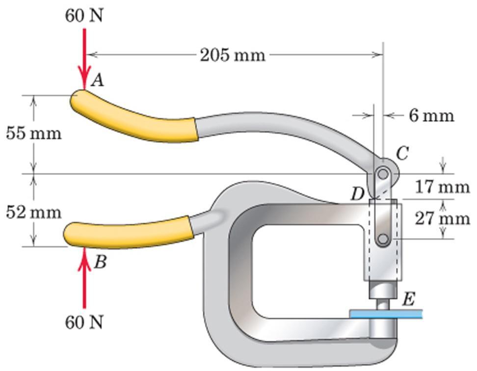
22 1. The clamp shown in the figure is frequently used in welding operations. Determine the clamping force on the two metal pieces at E and the magnitudes of the forces supported by pins A, B and D.

23 2. The elements of a rear suspension for a front-wheel-drive car are shown in the figure. Determine the magnitude of the force at each joint if the normal force exerted on the tire has a magnitude of 3600 N.
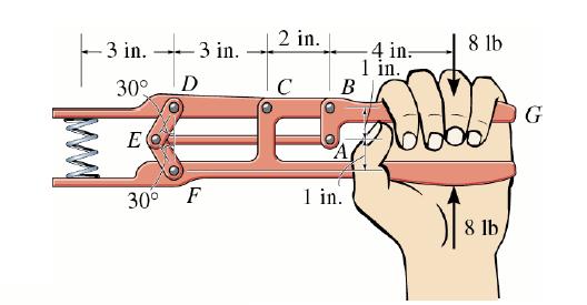
24 3. Determine the force P exerted on the twig G. Note that there is a horizontal line of symmetry for the handles, but there is no line of symmetry for the jaws.

25 4. Calculate the x- and y-components of all forces acting on each member of the loaded frame.

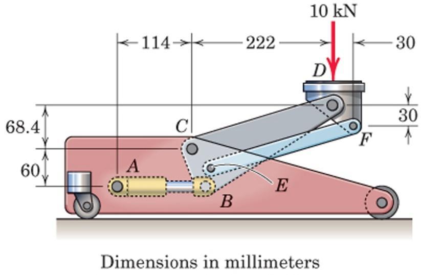
26 5. The truck shown is used to deliver food to aircraft. The elevated unit weighs 1000 kg with center of gravity at G. Determine the required force in the hydraulic cylinder AB.
27 6. A basketball hoop whose rim height is adjustable is shown. The supporting post ABCD weighs 400 N with the center of gravity at point C, and backboard-hoop assembly weighs 220 N with the center of gravity at point G. The height of the rim is adjustable by means of the screw and hand crank IJ, where the screw is vertical. If a person with 800 N weight hangs on the rim, determine the support reactions at D and the forces supported by all members. Hint: Member IJ is a two-force member.

28 7. The pruning mechanism of a pole saw is shown as it cuts a branch S. or the particular position drawn, the actuating cord is parallel to the pole and carries a tension of 120 N. Determine the shearing force P applied to the branch by the cutter and the total force supported by the pin at E. The force exerted by the light return spring at C is small and may be neglected.
29 8. In the frame shown determine the forces acting at pins A, B and D.

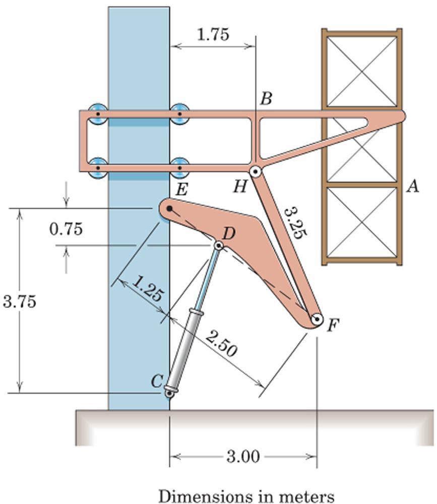
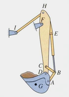
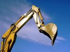
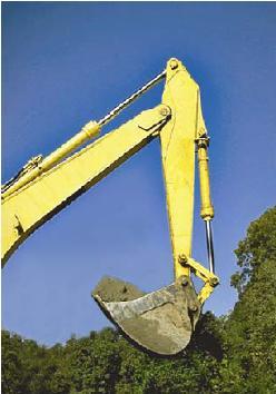
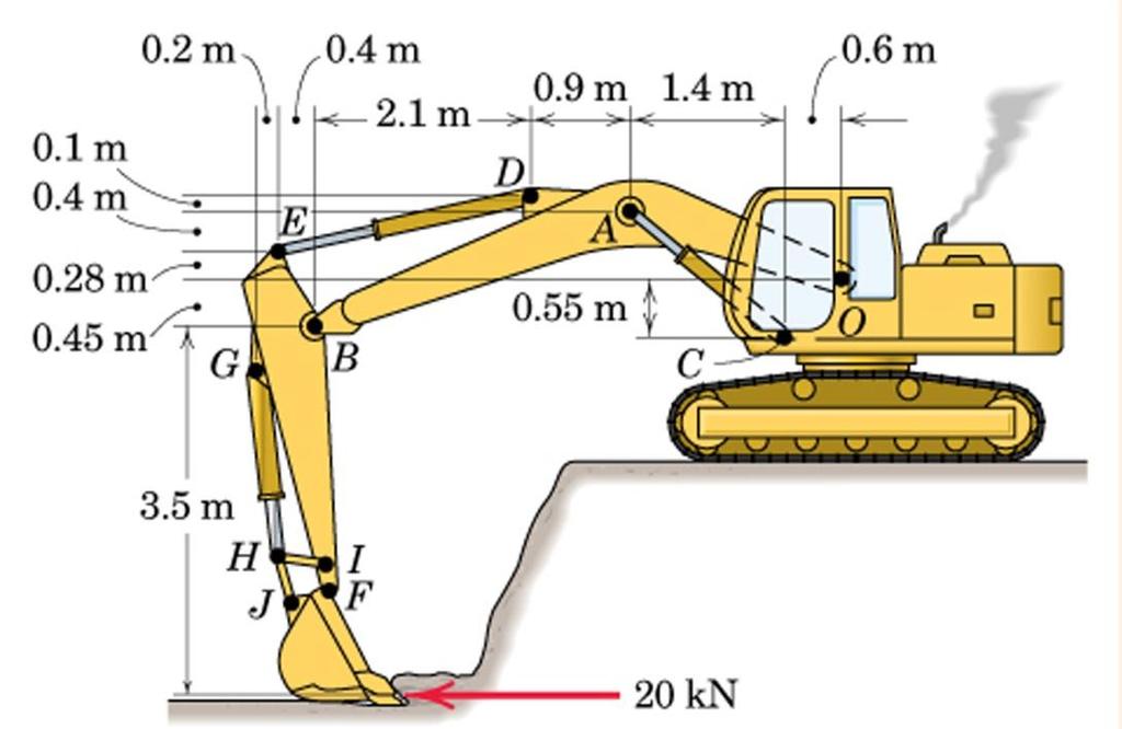
30 9. The mechanism in the figure is used to raise the bucket of a bulldozer. The bucket and its contents weigh 10 kn and have a center of gravity at H. Arm ABCD has a weight of 2 kn and a center of gravity at B, arm DEG has a weight of 1 kn and a center of gravity at E. The weights of the hydraulic cylinders can be neglected. Determine the forces in the hydraulic cylinders CJ, B and EI and also determine all the forces acting at arm DEG.
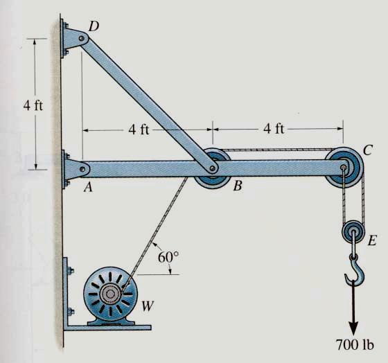
31 10. The linkage shown is used on a garbage truck to lift a 9000 N dumpster. Points A-G are pins, and member ABC is horizontal. or the position shown, when the dumpster just fully lifts off the ground, determine the force hydraulic cylinder C. Roller at G is contact with the dumpster.
32 A x A y G BD of dumpster N A A N A A N M y G y y x G x x G G A sin cos (600) 9000(1500) 0
33 E y E x CD G BD of member EDG M x y E (1500) E x CD 22500cos cos cos 45 E y (300) sin 45 0 E E G x y N N N
34 C rom equilibrium of whole system; E y E x B x B y M 900(1950) E C E 0 x N (900cos 45) E y 450 ( cos 45) C cos 45(450) 0
35 11. A hydraulic lift-table is used to raise a 1000 kg crate. It consists of a platform and two identical linkages on which hydraulic cylinders exert equal forces. In the figure only one linkage and one cylinder are shown. Members EDB and CG are each of length 2a and member AD is pinned to the midpoint of EDB. If the crate is placed on the table, so that half of its weight is supported by the system shown, determine the force exerted by each cylinder in raising the crate for q=60 o, a=0.70 m and L=3.20 m. Show that the result obtained is independent of the distance d.
36 Two-orce Members: AD, BC, CG, DH. BD of Platform W/2 A B C 30 o q=60 o AD B C x y 0 0 AD B x 0 C W 2 0 AD 0 B C W 2 C W 2 B Pulley C C BC C x y 0 0 CG CG sin 30 cos 30 BC C 0 0 C CG cos o CG
37 BD of CG C CG G CG CG BC sin 30 C q=60 cos 30 o q=60 o 30 o CG BD of BC BC C tan 30 BC BC
38 BD of EDB B B BC 30 o E y 1.4 m E D 0.7 m 0.61 m q=60 o DH H q=60 o E x Cosine theorem: Sine theorem: M DH E 0 DH DH DH 0. 7 sin B DH cos DH sin B 0. 7 BC tan N B C W / 2 DE sin 60 C 2 BC 0 EH 2 2DEEH cos 60 DH m o 0

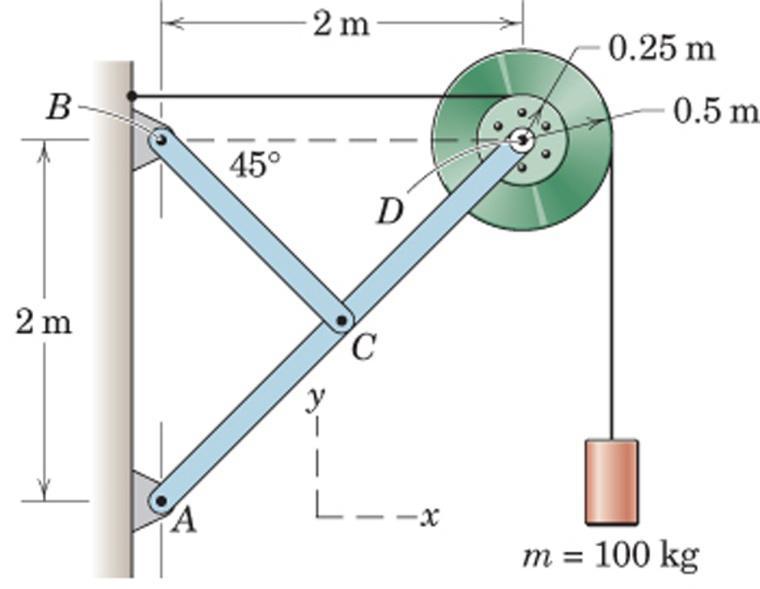
39 12. The mechanism is designed to keep its load level while raising it. A pin on the rim of the 80 cm diameter pulley fits in a slot on arm ABC. Arm ABC and DE are each 80 cm long and the package being lifted weighs 80 kn. The mechanism is raised by pulling on the rope that is wrapped around the pulley. Determine the force P applied to the rope and all the forces acting on arm ABC when the package has been lifted 80 cm as shown.
40 SOLUTION BD of Platform Two force member: ED BD of DE mm
41 BD of ABC BD of the pulley
42 13. A simple folding chair comprised of two identical frames, one on each side, is shown in the figure. The half frame shown carries half the weight of a 70 kg person. Determine all the forces acting on member B. Neglect the weights of the connecting elements (not shown) and the seat, and also the friction at points A, B and. Detail of contact at Dimensions in mm
43 Geometry of the Chair
44 SOLUTION Two force member: EG Equilibrium of the whole system: BD of DC
45 GE two force member BD of B
1. The toggle pliers are used for a variety of clamping purposes. For the handle position given by a=10 o and for a handle grip P=150 N, calculate
 1. The toggle pliers are used for a variet of clamping purposes. or the handle position given b a=10 o and for a handle grip P=150 N, calculate the clamping force C produced. Note that pins A and D are
Similar to trusses, frames are generally fixed, load carrying structures.
 Similar to trusses, frames are generally fixed, load carrying structures. The main difference between a frame and a truss is that in a frame at least one member is a multi force member (çoklu kuvvet elemanı).
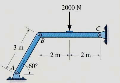
1. If it is known that the center pin A supports one-half of the vertical loading shown, determine the force in member BF.
 1. If it is known that the center pin A supports one-half of the vertical loading shown, determine the force in member B. Joint A AB A I. Cut D D B A 26 kn A I. Cut H 13 kn D B D A H 13 kn 2. Determine
Statics Chapter II Fall 2018 Exercises Corresponding to Sections 2.1, 2.2, and 2.3
 Statics Chapter II Fall 2018 Exercises Corresponding to Sections 2.1, 2.2, and 2.3 2 3 Determine the magnitude of the resultant force FR = F1 + F2 and its direction, measured counterclockwise from the
Eng Sample Test 4
 1. An adjustable tow bar connecting the tractor unit H with the landing gear J of a large aircraft is shown in the figure. Adjusting the height of the hook F at the end of the tow bar is accomplished by
MEE224: Engineering Mechanics Lecture 4
 Lecture 4: Structural Analysis Part 1: Trusses So far we have only analysed forces and moments on a single rigid body, i.e. bars. Remember that a structure is a formed by and this lecture will investigate
SOLUTION 8 1. a+ M B = 0; N A = 0. N A = kn = 16.5 kn. Ans. + c F y = 0; N B = 0
 8 1. The mine car and its contents have a total mass of 6 Mg and a center of gravity at G. If the coefficient of static friction between the wheels and the tracks is m s = 0.4 when the wheels are locked,
When a rigid body is in equilibrium, both the resultant force and the resultant couple must be zero.
 When a rigid body is in equilibrium, both the resultant force and the resultant couple must be zero. 0 0 0 0 k M j M i M M k R j R i R F R z y x z y x Forces and moments acting on a rigid body could be
TUTORIAL SHEET 1. magnitude of P and the values of ø and θ. Ans: ø =74 0 and θ= 53 0
 TUTORIAL SHEET 1 1. The rectangular platform is hinged at A and B and supported by a cable which passes over a frictionless hook at E. Knowing that the tension in the cable is 1349N, determine the moment
EQUILIBRIUM OF RIGID BODIES
 EQUILIBRIUM OF RIGID BODIES Equilibrium A body in equilibrium is at rest or can translate with constant velocity F = 0 M = 0 EQUILIBRIUM IN TWO DIMENSIONS Case where the force system acting on a rigid
Name. ME 270 Fall 2005 Final Exam PROBLEM NO. 1. Given: A distributed load is applied to the top link which is, in turn, supported by link AC.
 Name ME 270 Fall 2005 Final Exam PROBLEM NO. 1 Given: A distributed load is applied to the top link which is, in turn, supported by link AC. Find: a) Draw a free body diagram of link BCDE and one of link
CHAPTER 5 ANALYSIS OF STRUCTURES. Expected Outcome:
 CHAPTER ANALYSIS O STRUCTURES Expected Outcome: Able to analyze the equilibrium of structures made of several connected parts, using the concept of the equilibrium of a particle or of a rigid body, in
5.2 Rigid Bodies and Two-Dimensional Force Systems
 5.2 Rigid odies and Two-Dimensional Force Systems 5.2 Rigid odies and Two-Dimensional Force Systems Procedures and Strategies, page 1 of 1 Procedures and Strategies for Solving Problems Involving Equilibrium
ENT 151 STATICS. Contents. Introduction. Definition of a Truss
 CHAPTER 6 Analysis ENT 151 STATICS Lecture Notes: Mohd Shukry Abdul Majid KUKUM of Structures Contents Introduction Definition of a Truss Simple Trusses Analysis of Trusses by the Method of Joints Joints
3.1 CONDITIONS FOR RIGID-BODY EQUILIBRIUM
 3.1 CONDITIONS FOR RIGID-BODY EQUILIBRIUM Consider rigid body fixed in the x, y and z reference and is either at rest or moves with reference at constant velocity Two types of forces that act on it, the
acting on a body has two effects:
 The force acting on a body has two effects: the first one is the tendency to push or pull the body in the direction of the force, and the second one is to rotate the body about any fixed axis which does
6.6 FRAMES AND MACHINES APPLICATIONS. Frames are commonly used to support various external loads.
 6.6 FRAMES AND MACHINES APPLICATIONS Frames are commonly used to support various external loads. How is a frame different than a truss? How can you determine the forces at the joints and supports of a
Force Couple Systems = Reduction of a Force to an Equivalent Force and Moment (Moving a Force to Another Point) acting on a body has two effects:
 acting on a body has two effects:") ESULTANTS orce Couple Systems = eduction of a orce to an Equivalent orce and Moment (Moving a orce to Another Point) The force acting on a body has two effects: the first one is the tendency to push or
ESULTANTS orce Couple Systems = eduction of a orce to an Equivalent orce and Moment (Moving a orce to Another Point) The force acting on a body has two effects: the first one is the tendency to push or
11.1 Virtual Work Procedures and Strategies, page 1 of 2
 11.1 Virtual Work 11.1 Virtual Work rocedures and Strategies, page 1 of 2 rocedures and Strategies for Solving roblems Involving Virtual Work 1. Identify a single coordinate, q, that will completely define
ME Statics. Structures. Chapter 4
 ME 108 - Statics Structures Chapter 4 Outline Applications Simple truss Method of joints Method of section Germany Tacoma Narrows Bridge http://video.google.com/videoplay?docid=-323172185412005564&q=bruce+lee&pl=true
Announcements. Trusses Method of Joints
 Announcements Mountain Dew is an herbal supplement Today s Objectives Define a simple truss Trusses Method of Joints Determine the forces in members of a simple truss Identify zero-force members Class
Ishik University / Sulaimani Architecture Department. Structure. ARCH 214 Chapter -5- Equilibrium of a Rigid Body
 Ishik University / Sulaimani Architecture Department 1 Structure ARCH 214 Chapter -5- Equilibrium of a Rigid Body CHAPTER OBJECTIVES To develop the equations of equilibrium for a rigid body. To introduce
The case where there is no net effect of the forces acting on a rigid body
 The case where there is no net effect of the forces acting on a rigid body Outline: Introduction and Definition of Equilibrium Equilibrium in Two-Dimensions Special cases Equilibrium in Three-Dimensions
Static Equilibrium. University of Arizona J. H. Burge
 Static Equilibrium Static Equilibrium Definition: When forces acting on an object which is at rest are balanced, then the object is in a state of static equilibrium. - No translations - No rotations In
Announcements. Equilibrium of a Rigid Body
 Announcements Equilibrium of a Rigid Body Today s Objectives Identify support reactions Draw a free body diagram Class Activities Applications Support reactions Free body diagrams Examples Engr221 Chapter
Chapter - 1. Equilibrium of a Rigid Body
 Chapter - 1 Equilibrium of a Rigid Body Dr. Rajesh Sathiyamoorthy Department of Civil Engineering, IIT Kanpur hsrajesh@iitk.ac.in; http://home.iitk.ac.in/~hsrajesh/ Condition for Rigid-Body Equilibrium
The University of Melbourne Engineering Mechanics
 The University of Melbourne 436-291 Engineering Mechanics Tutorial Eleven Instantaneous Centre and General Motion Part A (Introductory) 1. (Problem 5/93 from Meriam and Kraige - Dynamics) For the instant
STATICS. Bodies. Vector Mechanics for Engineers: Statics VECTOR MECHANICS FOR ENGINEERS: Design of a support
 4 Equilibrium CHAPTER VECTOR MECHANICS FOR ENGINEERS: STATICS Ferdinand P. Beer E. Russell Johnston, Jr. Lecture Notes: J. Walt Oler Texas Tech University of Rigid Bodies 2010 The McGraw-Hill Companies,
READING QUIZ. 2. When using the method of joints, typically equations of equilibrium are applied at every joint. A) Two B) Three C) Four D) Six
 Two B) Three C) Four D) Six") READING QUIZ 1. One of the assumptions used when analyzing a simple truss is that the members are joined together by. A) Welding B) Bolting C) Riveting D) Smooth pins E) Super glue 2. When using the method
READING QUIZ 1. One of the assumptions used when analyzing a simple truss is that the members are joined together by. A) Welding B) Bolting C) Riveting D) Smooth pins E) Super glue 2. When using the method
Equilibrium of a Rigid Body. Engineering Mechanics: Statics
 Equilibrium of a Rigid Body Engineering Mechanics: Statics Chapter Objectives Revising equations of equilibrium of a rigid body in 2D and 3D for the general case. To introduce the concept of the free-body
STATICS. Vector Mechanics for Engineers: Statics VECTOR MECHANICS FOR ENGINEERS: Contents 9/3/2015
 6 Analsis CHAPTER VECTOR MECHANICS OR ENGINEERS: STATICS erdinand P. Beer E. Russell Johnston, Jr. of Structures Lecture Notes: J. Walt Oler Texas Tech Universit Contents Introduction Definition of a Truss
Chapter 6: Structural Analysis
 Chapter 6: Structural Analysis APPLICATIONS Trusses are commonly used to support a roof. For a given truss geometry and load, how can we determine the forces in the truss members and select their sizes?
SRSD 2093: Engineering Mechanics 2SRRI SECTION 19 ROOM 7, LEVEL 14, MENARA RAZAK
 SRSD 2093: Engineering Mechanics 2SRRI SECTION 19 ROOM 7, LEVEL 14, MENARA RAZAK SIMPLE TRUSSES, THE METHOD OF JOINTS, & ZERO-FORCE MEMBERS Today s Objectives: Students will be able to: a) Define a simple
0.3 m. 0.4 m. 0.3 m. A 2 kn. 0.4 m. tan γ = 7. (BC = kn) γ = Fx = BC cos θ + AC cos γ =0
 γ = Fx = BC cos θ + AC cos γ =0") Problem 6.4 etermine the aial forces in the members of the truss. kn 0.3 m 0.4 m 0.6 m 1. m Solution: irst, solve for the support reactions at and, and then use the method of joints to solve for the forces
Problem 6.4 etermine the aial forces in the members of the truss. kn 0.3 m 0.4 m 0.6 m 1. m Solution: irst, solve for the support reactions at and, and then use the method of joints to solve for the forces
AP Physics Multiple Choice Practice Torque
 AP Physics Multiple Choice Practice Torque 1. A uniform meterstick of mass 0.20 kg is pivoted at the 40 cm mark. Where should one hang a mass of 0.50 kg to balance the stick? (A) 16 cm (B) 36 cm (C) 44
Sample 5. Determine the tension in the cable and the horizontal and vertical components of reaction at the pin A. Neglect the size of the pulley.
 Sample 1 The tongs are designed to handle hot steel tubes which are being heat-treated in an oil bath. For a 20 jaw opening, what is the minimum coefficient of static friction between the jaws and the
FRAMES AND MACHINES Learning Objectives 1). To evaluate the unknown reactions at the supports and the interaction forces at the connection points of a
. To evaluate the unknown reactions at the supports and the interaction forces at the connection points of a") FRAMES AND MACHINES Learning Objectives 1). To evaluate the unknown reactions at the supports and the interaction forces at the connection points of a rigid frame in equilibrium by solving the equations
FRAMES AND MACHINES Learning Objectives 1). To evaluate the unknown reactions at the supports and the interaction forces at the connection points of a rigid frame in equilibrium by solving the equations
Equilibrium. Rigid Bodies VECTOR MECHANICS FOR ENGINEERS: STATICS. Eighth Edition CHAPTER. Ferdinand P. Beer E. Russell Johnston, Jr.
 Eighth E 4 Equilibrium CHAPTER VECTOR MECHANICS FOR ENGINEERS: STATICS Ferdinand P. Beer E. Russell Johnston, Jr. Lecture Notes: J. Walt Oler Texas Tech University of Rigid Bodies Contents Introduction
Hours / 100 Marks Seat No.
 17204 15162 3 Hours / 100 Marks Seat No. Instructions : (1) All Questions are compulsory. (2) Answer each next main Question on a new page. (3) Illustrate your answers with neat sketches wherever necessary.
Simple Machines. Bởi: OpenStaxCollege
 F Simple Machines Simple Machines Bởi: OpenStaxCollege Simple machines are devices that can be used to multiply or augment a force that we apply often at the expense of a distance through which we apply
 Connected Bodies 1. Two 10 kg bodies are attached to a spring balance as shown in figure. The reading of the balance will be 10 kg 10 kg 1) 0 kg-wt ) 10 kg-wt 3) Zero 4) 5 kg-wt. In the given arrangement,
Figure 9.1 (a) Six performers in the circus; (b) free-body diagram of the performers / Alan Thornton/Stone/Getty Images
 Six performers in the circus; (b) free-body diagram of the performers / Alan Thornton/Stone/Getty Images") Creatas In this chapter we use equilibrium analysis to look at loads internal to three types of systems: frames, machines, and trusses. By the end of this chapter, you will be able to systematically find
Creatas In this chapter we use equilibrium analysis to look at loads internal to three types of systems: frames, machines, and trusses. By the end of this chapter, you will be able to systematically find
Engineering Mechanics. Friction in Action
 Engineering Mechanics Friction in Action What is friction? Friction is a retarding force that opposes motion. Friction types: Static friction Kinetic friction Fluid friction Sources of dry friction Dry
Name Date Period PROBLEM SET: ROTATIONAL DYNAMICS
 Accelerated Physics Rotational Dynamics Problem Set Page 1 of 5 Name Date Period PROBLEM SET: ROTATIONAL DYNAMICS Directions: Show all work on a separate piece of paper. Box your final answer. Don t forget
STATICS. Friction VECTOR MECHANICS FOR ENGINEERS: Eighth Edition CHAPTER. Ferdinand P. Beer E. Russell Johnston, Jr.
 Eighth E 8 Friction CHAPTER VECTOR MECHANICS FOR ENGINEERS: STATICS Ferdinand P. Beer E. Russell Johnston, Jr. Lecture Notes: J. Walt Oler Texas Tech University Contents Introduction Laws of Dry Friction.
Vector Mechanics: Statics
 PDHOnline Course G492 (4 PDH) Vector Mechanics: Statics Mark A. Strain, P.E. 2014 PDH Online PDH Center 5272 Meadow Estates Drive Fairfax, VA 22030-6658 Phone & Fax: 703-988-0088 www.pdhonline.org www.pdhcenter.com
M D P L sin x FN L sin C W L sin C fl cos D 0.
 789 roblem 9.26 he masses of the ladder and person are 18 kg and 90 kg, respectively. he center of mass of the 4-m ladder is at its midpoint. If D 30, what is the minimum coefficient of static friction
Equilibrium of a Particle
 ME 108 - Statics Equilibrium of a Particle Chapter 3 Applications For a spool of given weight, what are the forces in cables AB and AC? Applications For a given weight of the lights, what are the forces
1. An experimental device imparts a force of magnitude F = 225 N to the front edge of the rim at A to simulate the effect of a slam dunk.
 1. An experimental device imparts a force of magnitude F = 225 N to the front edge of the rim at A to simulate the effect of a slam dunk. Determine the moments of the force F about point and about point
VALLIAMMAI ENGINEERING COLLEGE SRM NAGAR, KATTANKULATHUR DEPARTMENT OF MECHANICAL ENGINEERING
 VALLIAMMAI ENGINEERING COLLEGE SRM NAGAR, KATTANKULATHUR 603203 DEPARTMENT OF MECHANICAL ENGINEERING BRANCH: MECHANICAL YEAR / SEMESTER: I / II UNIT 1 PART- A 1. State Newton's three laws of motion? 2.
ASSOCIATE DEGREE IN ENGINEERING EXAMINATIONS SEMESTER /13
 ASSOCIATE DEGREE IN ENGINEERING EXAMINATIONS SEMESTER 2 2012/13 COURSE NAME: ENGINEERING MECHANICS - STATICS CODE: ENG 2008 GROUP: AD ENG II DATE: May 2013 TIME: DURATION: 2 HOURS INSTRUCTIONS: 1. This
ENGR-1100 Introduction to Engineering Analysis. Lecture 19
 ENGR-1100 Introduction to Engineering Analysis Lecture 19 SIMPLE TRUSSES, THE METHOD OF JOINTS, & ZERO-FORCE MEMBERS Today s Objectives: Students will be able to: In-Class Activities: a) Define a simple
(counterclockwise - ccw)
") Problems (on oment) 1. The rod on the power control mechanism for a business jet is subjected to a force of 80 N. Determine the moment of this force about the bearing at. + 0.15sin 6080sin 00.15cos60 80
Problems (on oment) 1. The rod on the power control mechanism for a business jet is subjected to a force of 80 N. Determine the moment of this force about the bearing at. + 0.15sin 6080sin 00.15cos60 80
STATICS VECTOR MECHANICS FOR ENGINEERS: Eleventh Edition CHAPTER. Ferdinand P. Beer E. Russell Johnston, Jr. David F. Mazurek
 Eleventh E 6 Analysis CHAPTER VECTOR MECHANICS OR ENGINEERS: STATICS erdinand P. Beer E. Russell Johnston, Jr. David. Mazurek of Structures Contents Application Introduction Definition of a Truss Simple
STATICS. FE Review. Statics, Fourteenth Edition R.C. Hibbeler. Copyright 2016 by Pearson Education, Inc. All rights reserved.
 STATICS FE Review 1. Resultants of force systems VECTOR OPERATIONS (Section 2.2) Scalar Multiplication and Division VECTOR ADDITION USING EITHER THE PARALLELOGRAM LAW OR TRIANGLE Parallelogram Law: Triangle
1. Attempt any ten of the following : 20
 *17204* 17204 21314 3 Hours/100 Marks Seat No. Instructions : (1) All questions are compulsory. (2) Answer each next main question on a new page. (3) Illustrate your answers with neat sketches wherever
PHYS 101 Previous Exam Problems. Force & Motion I
 PHYS 101 Previous Exam Problems CHAPTER 5 Force & Motion I Newton s Laws Vertical motion Horizontal motion Mixed forces Contact forces Inclines General problems 1. A 5.0-kg block is lowered with a downward
E 490 FE Exam Prep. Engineering Mechanics
 E 490 FE Exam Prep Engineering Mechanics 2008 E 490 Course Topics Statics Newton s Laws of Motion Resultant Force Systems Moment of Forces and Couples Equilibrium Pulley Systems Trusses Centroid of an
KINGS COLLEGE OF ENGINEERING ENGINEERING MECHANICS QUESTION BANK UNIT I - PART-A
 KINGS COLLEGE OF ENGINEERING ENGINEERING MECHANICS QUESTION BANK Sub. Code: CE1151 Sub. Name: Engg. Mechanics UNIT I - PART-A Sem / Year II / I 1.Distinguish the following system of forces with a suitable
Final Exam - Spring
 EM121 Final Exam - Spring 2011-2012 Name : Section Number : Record all your answers to the multiple choice problems (1-15) by filling in the appropriate circle. All multiple choice answers will be graded
PHY 1150 Doug Davis Chapter 8; Static Equilibrium 8.3, 10, 22, 29, 52, 55, 56, 74
 PHY 1150 Doug Davis Chapter 8; Static Equilibrium 8.3, 10, 22, 29, 52, 55, 56, 74 8.3 A 2-kg ball is held in position by a horizontal string and a string that makes an angle of 30 with the vertical, as
WEEK 1 Dynamics of Machinery
 WEEK 1 Dynamics of Machinery References Theory of Machines and Mechanisms, J.J. Uicker, G.R.Pennock ve J.E. Shigley, 2003 Makine Dinamiği, Prof. Dr. Eres SÖYLEMEZ, 2013 Uygulamalı Makine Dinamiği, Jeremy
Lecture 23. ENGR-1100 Introduction to Engineering Analysis FRAMES S 1
 ENGR-1100 Introduction to Engineering Analysis Lecture 23 Today s Objectives: Students will be able to: a) Draw the free body diagram of a frame and its members. FRAMES b) Determine the forces acting at
Chapter Objectives. Copyright 2011 Pearson Education South Asia Pte Ltd
 Chapter Objectives To develop the equations of equilibrium for a rigid body. To introduce the concept of the free-body diagram for a rigid body. To show how to solve rigid-body equilibrium problems using
SIMPLE TRUSSES, THE METHOD OF JOINTS, & ZERO-FORCE MEMBERS
 SIMPLE TRUSSES, THE METHOD OF JOINTS, & ZERO-FORCE MEMBERS Today s Objectives: Students will be able to: a) Define a simple truss. b) Determine the forces in members of a simple truss. c) Identify zero-force
if the initial displacement and velocities are zero each. [ ] PART-B
![if the initial displacement and velocities are zero each. [ ] PART-B](/thumbs/86/94772448.jpg "if the initial displacement and velocities are zero each. [ ] PART-B") Set No - 1 I. Tech II Semester Regular Examinations ugust - 2014 ENGINEERING MECHNICS (Common to ECE, EEE, EIE, io-tech, E Com.E, gri. E) Time: 3 hours Max. Marks: 70 Question Paper Consists of Part- and
Set No - 1 I. Tech II Semester Regular Examinations ugust - 2014 ENGINEERING MECHNICS (Common to ECE, EEE, EIE, io-tech, E Com.E, gri. E) Time: 3 hours Max. Marks: 70 Question Paper Consists of Part- and
2008 FXA THREE FORCES IN EQUILIBRIUM 1. Candidates should be able to : TRIANGLE OF FORCES RULE
 THREE ORCES IN EQUILIBRIUM 1 Candidates should be able to : TRIANGLE O ORCES RULE Draw and use a triangle of forces to represent the equilibrium of three forces acting at a point in an object. State that
15-30 Chapter 15: Homework Problems
 15-30 hapter 15: Homework Prolems 8.1 Let s start with a simple prolem. Determining the forces on the front and rear tires of car that weighs 2400 ls. You may assume that a = 2.15ft. and = 2.65ft.. What
Hours / 100 Marks Seat No.
 17204 15116 3 Hours / 100 Seat No. Instructions (1) All Questions are Compulsory. (2) Answer each next main Question on a new page. (3) Illustrate your answers with neat sketches wherever necessary. (4)
DYNAMICS ME HOMEWORK PROBLEM SETS
 DYNAMICS ME 34010 HOMEWORK PROBLEM SETS Mahmoud M. Safadi 1, M.B. Rubin 2 1 safadi@technion.ac.il, 2 mbrubin@technion.ac.il Faculty of Mechanical Engineering Technion Israel Institute of Technology Spring
Engineering Mechanics: Statics STRUCTURAL ANALYSIS. by Dr. Ibrahim A. Assakkaf SPRING 2007 ENES 110 Statics
 CHAPTER Engineering Mechanics: Statics STRUCTURAL ANALYSIS College of Engineering Department of Mechanical Engineering Tenth Edition 6a by Dr. Ibrahim A. Assakkaf SPRING 2007 ENES 110 Statics Department
Name: Date: Period: AP Physics C Rotational Motion HO19
 1.) A wheel turns with constant acceleration 0.450 rad/s 2. (9-9) Rotational Motion H19 How much time does it take to reach an angular velocity of 8.00 rad/s, starting from rest? Through how many revolutions
Chapter 8. Rotational Equilibrium and Rotational Dynamics. 1. Torque. 2. Torque and Equilibrium. 3. Center of Mass and Center of Gravity
 Chapter 8 Rotational Equilibrium and Rotational Dynamics 1. Torque 2. Torque and Equilibrium 3. Center of Mass and Center of Gravity 4. Torque and angular acceleration 5. Rotational Kinetic energy 6. Angular
Tension, Compression, and Shear
 01Ch01.qxd 2/10/09 7:32 PM Page 1 1 ension, Compression, and Shear Normal Stress and Strain Problem 1.2-1 A hollow circular post ABC (see figure) supports a load P 1 7.5 kn acting at the top. A second
SOLUTION 8 7. To hold lever: a+ M O = 0; F B (0.15) - 5 = 0; F B = N. Require = N N B = N 0.3. Lever,
 - 5 = 0; F B = N. Require = N N B = N 0.3. Lever,") 8 3. If the coefficient of static friction at is m s = 0.4 and the collar at is smooth so it only exerts a horizontal force on the pipe, determine the minimum distance x so that the bracket can support
8 3. If the coefficient of static friction at is m s = 0.4 and the collar at is smooth so it only exerts a horizontal force on the pipe, determine the minimum distance x so that the bracket can support
Force and Moment. Figure 1 Figure 2
 Force and Moment 1 Determine the magnitude and direction of the resultant of the two forces shown, using (a) the parallelogram law (b) the sine law. [1391 N, 47.8 ] Figure 1 Figure 2 2 The force F of magnitude
Chapter 04 Equilibrium of Rigid Bodies
 Chapter 04 Equilibrium of Rigid Bodies Application Engineers designing this crane will need to determine the forces that act on this body under various conditions. 4-2 Introduction For a rigid body, the
Physics, Chapter 3: The Equilibrium of a Particle
 University of Nebraska - Lincoln DigitalCommons@University of Nebraska - Lincoln Robert Katz Publications Research Papers in Physics and Astronomy 1-1958 Physics, Chapter 3: The Equilibrium of a Particle
To show how to determine the forces in the members of a truss using the method of joints and the method of sections.
 5 Chapter Objectives To show how to determine the forces in the members of a truss using the method of joints and the method of sections. To analyze the forces acting on the members of frames and machines
Review PHYS114 Chapters 4-7
 Review PHYS114 Chapters 4-7 MULTIPLE CHOICE. Choose the one alternative that best completes the statement or answers the question. 1) A 27 kg object is accelerated at a rate of 1.7 m/s 2. What force does
UNIVERSITY OF SASKATCHEWAN GE MECHANICS III FINAL EXAM APRIL 18, 2011 Professor A. Dolovich A CLOSED BOOK EXAMINATION TIME: 3 HOURS
 UNIVERSITY OF SASKATCHEWAN GE 226.3 MECHANICS III FINAL EXAM APRIL 18, 2011 Professor A. Dolovich A CLOSED BOOK EXAMINATION TIME: 3 HOURS LAST NAME (printed): FIRST NAME (printed): STUDENT NUMBER: EXAMINATION
Newton s Third Law Newton s Third Law: For each action there is an action and opposite reaction F
 FRAMES AND MACHINES Learning Objectives 1). To evaluate the unknown reactions at the supports and the interaction forces at the connection points of a rigid frame in equilibrium by solving the equations
CHAPTER 4 NEWTON S LAWS OF MOTION
 62 CHAPTER 4 NEWTON S LAWS O MOTION CHAPTER 4 NEWTON S LAWS O MOTION 63 Up to now we have described the motion of particles using quantities like displacement, velocity and acceleration. These quantities
EQUILIBRIUM OF RIGID BODIES IN TWO DIMENSIONS
 EQUILIBRIUM OF RIGID BODIES IN TWO DIMENSIONS If the resultant of all external forces acting on a rigid body is zero, then the body is said to be in equilibrium. Therefore, in order for the rigid body
2.1 Introduction to Simple Machines
 2.1 Introduction to Simple Machines 2.1 Introduction to Simple Machines Simple Machines Unit DO NOT WRITE ANYWHERE IN THIS PACKAGE One of the few properties that separate us from animals is our ability
STATICS. Bodies VECTOR MECHANICS FOR ENGINEERS: Ninth Edition CHAPTER. Ferdinand P. Beer E. Russell Johnston, Jr.
 N E 4 Equilibrium CHAPTER VECTOR MECHANICS FOR ENGINEERS: STATICS Ferdinand P. Beer E. Russell Johnston, Jr. Lecture Notes: J. Walt Oler Texas Tech University of Rigid Bodies 2010 The McGraw-Hill Companies,
It will be most difficult for the ant to adhere to the wheel as it revolves past which of the four points? A) I B) II C) III D) IV
 I B) II C) III D) IV") AP Physics 1 Lesson 16 Homework Newton s First and Second Law of Rotational Motion Outcomes Define rotational inertia, torque, and center of gravity. State and explain Newton s first Law of Motion as it
AP Physics 1 Lesson 16 Homework Newton s First and Second Law of Rotational Motion Outcomes Define rotational inertia, torque, and center of gravity. State and explain Newton s first Law of Motion as it
Forces & NEWTON S LAWS HOMEWORK
 1 Forces & NEWTON S LAWS HOMEWORK BASIC CONCEPTS OF MASS VS. WEIGHT VS. VOLUME VS. DENSITY MULTIPLE CHOICE: You have one kilogram of feathers and one kilogram of lead. Which has more: 1. mass? 3. weight?
Statics deal with the condition of equilibrium of bodies acted upon by forces.
 Mechanics It is defined as that branch of science, which describes and predicts the conditions of rest or motion of bodies under the action of forces. Engineering mechanics applies the principle of mechanics
The University of Melbourne Engineering Mechanics
 The University of Melbourne 436-291 Engineering Mechanics Tutorial Four Poisson s Ratio and Axial Loading Part A (Introductory) 1. (Problem 9-22 from Hibbeler - Statics and Mechanics of Materials) A short
UNIT D: MECHANICAL SYSTEMS
 1 UNIT D: MECHANICAL SYSTEMS Science 8 2 Section 2.0 AN UNDERSTANDING OF MECHANICAL ADVANTAGE AND WORK HELPS IN DETERMINING THE EFFICIENCY OF MACHINES. 1 3 MACHINES MAKE WORK EASIER Topic 2.1 4 WHAT WOULD
and F NAME: ME rd Sample Final Exam PROBLEM 1 (25 points) Prob. 1 questions are all or nothing. PROBLEM 1A. (5 points)
 Prob. 1 questions are all or nothing. PROBLEM 1A. (5 points)") ME 270 3 rd Sample inal Exam PROBLEM 1 (25 points) Prob. 1 questions are all or nothing. PROBLEM 1A. (5 points) IND: In your own words, please state Newton s Laws: 1 st Law = 2 nd Law = 3 rd Law = PROBLEM
ME 270 3 rd Sample inal Exam PROBLEM 1 (25 points) Prob. 1 questions are all or nothing. PROBLEM 1A. (5 points) IND: In your own words, please state Newton s Laws: 1 st Law = 2 nd Law = 3 rd Law = PROBLEM
F = 140 N. 1. A mechanic pulls on the 13-mm combination wrench with the 140 N force shown. Determine the moment of this force about the bolt center O.
 95sin15 1. mechanic pulls on the 1-mm combination wrench with the 140 N force shown. Determine the moment of this force about the bolt center. //y = 140 N y = 140cos5 N 15 o 5 o + o 15 o 95cos15 //x x
PHY 126 Lecture Notes Chapter 10
 Chapter 10 Simple Machines OBJECTIVES Define a machine Examine energy transfer in machine to determine Mechanical Advantage and Energy Efficiency KEY WORDS: Simple and complex machines, Effort and resistance
Engineering Mechanics: Statics in SI Units, 12e
 Engineering Mechanics: Statics in SI Units, 12e 5 Equilibrium of a Rigid Body Chapter Objectives Develop the equations of equilibrium for a rigid body Concept of the free-body diagram for a rigid body
Lecture 0. Statics. Module 1. Overview of Mechanics Analysis. IDeALab. Prof. Y.Y.KIM. Solid Mechanics
 Lecture 0. Statics Module 1. Overview of Mechanics Analysis Overview of Mechanics Analysis Procedure of Solving Mechanics Problems Objective : Estimate the force required in the flexor muscle Crandall,
4) Vector = and vector = What is vector = +? A) B) C) D) E)
 Vector = and vector = What is vector = +? A) B) C) D) E)") 1) Suppose that an object is moving with constant nonzero acceleration. Which of the following is an accurate statement concerning its motion? A) In equal times its speed changes by equal amounts. B) In
1) Suppose that an object is moving with constant nonzero acceleration. Which of the following is an accurate statement concerning its motion? A) In equal times its speed changes by equal amounts. B) In
The centroid of an area is defined as the point at which (12-2) The distance from the centroid of a given area to a specified axis may be found by
 The distance from the centroid of a given area to a specified axis may be found by") Unit 12 Centroids Page 12-1 The centroid of an area is defined as the point at which (12-2) The distance from the centroid of a given area to a specified axis may be found by (12-5) For the area shown
Unit 12 Centroids Page 12-1 The centroid of an area is defined as the point at which (12-2) The distance from the centroid of a given area to a specified axis may be found by (12-5) For the area shown
8.1 Internal Forces in Structural Members
 8.1 Internal Forces in Structural Members 8.1 Internal Forces in Structural Members xample 1, page 1 of 4 1. etermine the normal force, shear force, and moment at sections passing through a) and b). 4