Numerical Simulation of Pressure Surge with the Method of Characteristics
|
|
|
- Sharon Washington
- 5 years ago
- Views:
Transcription
1 Numerical Simulation of Pressure Surge with the Method of Characteristics R. Fiereder Saint Petersburg, Russia
2 Content Motivation Governing Equations Continuity Equation Momentum Equation Method of Characteristics Implementation Boundary Conditions pplication pressure surge oscillating valve surge chamber oscillations power plant simulation 2

3 Motivation Simulation of interaction of plant components Identification of resonance cases 3
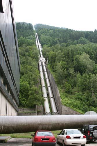
4 Motivation pump station power station III surge chamber power station I power station II 4
5 Governing Equations h Loss y h S h O z v h U L 1D unsteady compressible Continuity equation Momentum equation 5
6 Continuity Equation 1 dρ ρ 1 d v 0 Continuity ( ρ) ( ρv) t Product rule 0 ρ ρ v ρ v ρv ρ t t ρ 1 v 1 1 Total differential d d t d 0 y z d(ρ) d ρ 2 v 2 2 6
7 Continuity Equation 1 d 2R E s R dp ( 2 1 μ ) s σ ϕ Circular Pipe d 2πR dr 1 d ε ϕ d 2 σ a E, R μ No aial displacement / Hooke s law σ ϕ μσ a σ a μσ ϕ εϕ ER s << R d σ ϕ R s dp 2R E F 7
8 Continuity Equation Fluid compressibility 1 dρ ρ 1 E F dp Hooke s law applies E F dp dv V Mass in Control Volume is constant dm Vdρ ρdv 0 dv V dρ ρ 8
9 Continuity Equation p t v p ρa 2 v 0 dp 1 2R 2 EF ERs E Sys v ( 1 μ ) 0 2 a E Sys ρ 9
10 Momentum Equation 1 p ρ g z gj e v v v t 0 Momentum conservation i F i di y Pressure force p F P d p 1 1 τ 0 v p 2 2 Gravity force z F g ρg d z d τ 0 Friction force Fτ 0 2πRτ d τ 0 ρλ v v 8 4J e gr λ v 2 10
11 11 Final Set of Equations First order hyperbolic differential equation system Two dependent variables p, v Two independent variables, t a, ρ, J e are parameters of the system Solution by means of Method of Characteristics 0 2 v a p v t p ρ 0 1 t v v v gj z g p e ρ
12 12 Method of Characteristics Hyperbolic differential equation system Interferences propagate at a certain speed Eistence of constant variables along characteristic lines : G v a p v t p ρ G t v v v gj z g p e ρ G 2 G 1 G ξ 0 z J g dp dv e ξ ρξ ξρ 1 2 a v d ρa ξ 1 ± ( ) p v t p v a v t v ρξ ξ ξρ 0 ± ± C R d Riemann Variables
13 Method of Characteristics t dv 1 dp g J ρa d C v a e z d R 0 t 0 Δt C C - dv C 1 ρa d dp g J v a e z d R 0 t
14 Method of Characteristics Calculate values in P from known values in Point and B Integrate R ± along C ± P 1 P P dv dp g J g a ρ e P z 0 t t 0 Δt P C C - P B 1 dv ρa P B dp g P B J g e P B z 0 Two equations for two unknown variables t 0 B
15 Method of Characteristics-Summary t Solution is only valid on Characteristics t 0 Δt C - rea of influence C B rea of influence t 0 P rea of dependence 0 1 Characteristics separate two different solution domains t t 0 Δt P C C - rea of dependence t 0 B
16 Implementation Simplifications P a >> v d C a straight lines, velocity v is not known along C -> Friction term has to be approimated 2 J e J v Jv v Δt Ο( Δt) J e, Δ aδt Δt t Boundary Condition Boundary Condition Required Computational grid Steady-state solution for the system Boundary condition providing a disturbance Δt steady state Δ 16
17 Implementation Get system parameters Start read in parameters Initialize system Calculate Wave velocity a Generate calculation grid Calculate steady state solution Stationary Hydraulics Calculate solution for time t initialize system calculate steady state solution t t 0 calculate solution at time t write results? Yes write results to file No Yes t Δt t < t ma? No Stop 17
18 Implementation Method for calculating new time level C t P 1 ( vp v) ( pp p) gj e, Δt 0 ρa 1 1 vp pp v p gj e, Δt 0 ρa 1444 ρa K Δt C C - B C - analog i-1 i i1 v P K B K 2 p P ρa( K B K 2 ) 18
19 Implementation Calculate λ Evaluate boundary condition Calculate solution for inner field call from main calculate λ for friction term boundary condition left end i 0 Calculate K and K - boundary condition right end i i ma back to main i 1 Yes calculate v and p for point i i > i? ma No Yes No i i < i ma? i 0 - calculate K and K for point i 19
20 Boundary Conditions Static passive active Reservoir Valve static passive active f ( p, v) f ( p, v, t) Dynamic passive surge chamber dynamic f ( p, dp dv v, ) f dp dv ( p, v,, t) active Francis Turbine 20
21 Boundary Conditions Reservoir p const. v is calculated compression waves are reflected as epansions waves epansions waves are reflected as compression waves Wall v 0 p is calculated waves are reflected 21
22 Boundary Conditions Valve v f( Δp, τ, ζ ) v 1 ζτ 2 p0 p ρ 1 ζ > loss coefficient τ valve pipe τ ζ/ζ ma 0.6 α
23 Boundary Conditions Surge chamber (h) W p W can not be computed directly Q W (h w, ) h W Q W,L Q W,R predictor corrector scheme guess for p W calculate Q W dh W 1 ( h) ( Q Q ) W, L W, R correct p W correct Q W iterate till convergence Δh W h h W, t t 0 Δt W, 0 23
24 Boundary Conditions Turbine Machine data Mass moment of inertia of machine and rotating fluid Hill chart Generator η q 1 n 1 Governor Power Grid ω ω. τ. τ 24
25 T R ρav 0 pplication PRESSURE SURGE Joukowski - pressure surge ( Жуковский ) p(t) p 0 -ρav 0 sudden closure of a Valve kinetic energy of fluid is converted in pressure t[s] p(t) p 0 t[s] 25
26 pplication OSCILLTING VLVE T τ T R Results pressure and velocity in time at the valve /L 0 τ pressure and velocity in time in middle of the pipe T R τ valve pipe τ v/v ma p/p ma /L
27 pplication OSCILLTING VLVE Tτ 2TR Pressure and velocity variation along pipe Tτ 2TR 27
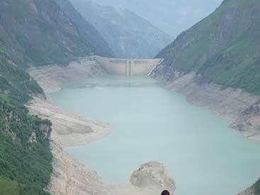
28 pplication SURGE CHMBER OSCILLTION surge chamber surge chamber reduces pressure fluctuations reservoir hydraulic uncoupling of pressure tunnel from penstock Improvement of control m pressure tunnel penstock m surge camber oscillation Interaction of high frequent pressure waves and low frequent inertia waves 28
29 pplication SURGE CHMBER OSCILLTION Model Δ Q 0 z W Q W W 270 m 250 m τ Δ [m] Δt [s] a [m/s] 2 W 79.0 [m ] D 2.5 [m] 3 Q [m /s] 1714m 686m D τ 0 m 0 t 0 t 29
30 pplication SURGE CHMBER OSCILLTION Results 7.5 Elevation of surge chamber water surface Zustandsdiagramm z[m] W z W [m] t [s] Q W [m /s] 30
31 pplication SURGE CHMBER OSCILLTION 3.35 Results pressure at the lower end of the penstock pressure at the upper end of the penstock p [MPa] X Detail X p W p Valve t [s] 31
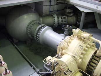
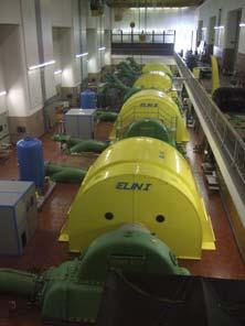
32 pplication POWER PLNT Model Simulation of plant, governor, grid and machine Francis turbine Isolated grid 500m 50m 0m 500 m. ω, ω,... Gov. τ Geno ω Grid D 0.8 [m] 1 a 1230 [m/s] 1 D 0.6 [m] 2 a 1300 [m/s] 2 Δt 8.6 [ms] P 1.0 [MW] T,ma 100 m 32
33 pplication POWER PLNT 1.2 p T ω 1 Geno Grid 0.8 v t ω 0.6 ω, ω,.... Gov. τ 0.4 P T P Geno start up τ open loop control to overcome mass moment of inertia 0.2 synchronization t [s] closed loop control by governor 33
34 pplication POWER PLNT ω Grid 1 p T v t Geno ω ω, ω,.... Gov. τ 0.4 load rejection 0.2 Sudden load rejection caused by failure in grid or generator 0 P Geno τ P T t [s] 34
35 Thank you for your attention! 35
36 Implementation Method for calculating new time level t t 0 Initial solution constant velocity low pressure Δt
37 Implementation Method for calculating new time level t t 1 valve closes suddenly Δt
38 Implementation Method for calculating new time level t t 1.5 disturbance propagates upstream half time step Δt
39 Implementation Method for calculating new time level t t 2.0 Net time level calculate solution on intersection Point Δt
40 Implementation Method for calculating new time level t t 2.0 Δt
41 Implementation Method for calculating new time level t t 3.0 Δt
42 Implementation Method for calculating new time level t t 3.0 Δt
Lesson 6 Review of fundamentals: Fluid flow
 Lesson 6 Review of fundamentals: Fluid flow The specific objective of this lesson is to conduct a brief review of the fundamentals of fluid flow and present: A general equation for conservation of mass
Thermodynamics ENGR360-MEP112 LECTURE 7
 Thermodynamics ENGR360-MEP11 LECTURE 7 Thermodynamics ENGR360/MEP11 Objectives: 1. Conservation of mass principle.. Conservation of energy principle applied to control volumes (first law of thermodynamics).
BERNOULLI EQUATION. The motion of a fluid is usually extremely complex.
 BERNOULLI EQUATION The motion of a fluid is usually extremely complex. The study of a fluid at rest, or in relative equilibrium, was simplified by the absence of shear stress, but when a fluid flows over
Design of Restricted Orifice Surge Tank
 Design of Restricted Orifice Surge Tank August 3, 13 Contents 1. Necessity of Surge Tank 1. Requirements for Hydraulic Design of Restricted Orifice Surge Tank 1 3. Fundamental Differential Equations 1
EGN 3353C Fluid Mechanics
 Lecture 8 Bernoulli s Equation: Limitations and Applications Last time, we derived the steady form of Bernoulli s Equation along a streamline p + ρv + ρgz = P t static hydrostatic total pressure q = dynamic
CIVE HYDRAULIC ENGINEERING PART II Pierre Julien Colorado State University
 1 CIVE 401 - HYDRAULIC ENGINEERING PART II Pierre Julien Colorado State University Problems with and are considered moderate and those with are the longest and most difficult. In 2018 solve the problems
ME 305 Fluid Mechanics I. Part 8 Viscous Flow in Pipes and Ducts. Flow in Pipes and Ducts. Flow in Pipes and Ducts (cont d)
") ME 305 Fluid Mechanics I Flow in Pipes and Ducts Flow in closed conduits (circular pipes and non-circular ducts) are very common. Part 8 Viscous Flow in Pipes and Ducts These presentations are prepared
ME 305 Fluid Mechanics I Flow in Pipes and Ducts Flow in closed conduits (circular pipes and non-circular ducts) are very common. Part 8 Viscous Flow in Pipes and Ducts These presentations are prepared
Binary-coded and real-coded genetic algorithm in pipeline flow optimization
 Mathematical Communications 41999), 35-42 35 Binary-coded and real-coded genetic algorithm in pipeline flow optimization Senka Vuković and Luka Sopta Abstract. The mathematical model for the liquid-gas
REE 307 Fluid Mechanics II. Lecture 1. Sep 27, Dr./ Ahmed Mohamed Nagib Elmekawy. Zewail City for Science and Technology
 REE 307 Fluid Mechanics II Lecture 1 Sep 27, 2017 Dr./ Ahmed Mohamed Nagib Elmekawy Zewail City for Science and Technology Course Materials drahmednagib.com 2 COURSE OUTLINE Fundamental of Flow in pipes
ME 305 Fluid Mechanics I. Chapter 8 Viscous Flow in Pipes and Ducts
 ME 305 Fluid Mechanics I Chapter 8 Viscous Flow in Pipes and Ducts These presentations are prepared by Dr. Cüneyt Sert Department of Mechanical Engineering Middle East Technical University Ankara, Turkey
Where does Bernoulli's Equation come from?
 Where does Bernoulli's Equation come from? Introduction By now, you have seen the following equation many times, using it to solve simple fluid problems. P ρ + v + gz = constant (along a streamline) This
Dynamic Behavior of a 2 Variable Speed Pump- Turbine Power Plant
 Paper ID 754 Dynamic Behavior of a Variable Speed Pump- Turbine Power Plant (1) Y. Pannatier, () C. Nicolet, (1) B. Kawkabani (*), (1) J.-J. Simond (*), (1) Ph. Allenbach (*) Member IEEE (1) Ecole Polytechnique
vector H. If O is the point about which moments are desired, the angular moment about O is given:
 The angular momentum A control volume analysis can be applied to the angular momentum, by letting B equal to angularmomentum vector H. If O is the point about which moments are desired, the angular moment
Reynolds, an engineering professor in early 1880 demonstrated two different types of flow through an experiment:
 7 STEADY FLOW IN PIPES 7.1 Reynolds Number Reynolds, an engineering professor in early 1880 demonstrated two different types of flow through an experiment: Laminar flow Turbulent flow Reynolds apparatus
Hydraulic (Fluid) Systems
 Systems") Hydraulic (Fluid) Systems Basic Modeling Elements Resistance apacitance Inertance Pressure and Flow Sources Interconnection Relationships ompatibility Law ontinuity Law Derive Input/Output Models ME375
Hydraulic (Fluid) Systems Basic Modeling Elements Resistance apacitance Inertance Pressure and Flow Sources Interconnection Relationships ompatibility Law ontinuity Law Derive Input/Output Models ME375
43. A person sits on a freely spinning lab stool that has no friction in its axle. When this person extends her arms,
 43. A person sits on a freely spinning lab stool that has no friction in its axle. When this person extends her arms, A) her moment of inertia increases and her rotational kinetic energy remains the same.
Chapter 8: Flow in Pipes
 8-1 Introduction 8-2 Laminar and Turbulent Flows 8-3 The Entrance Region 8-4 Laminar Flow in Pipes 8-5 Turbulent Flow in Pipes 8-6 Fully Developed Pipe Flow 8-7 Minor Losses 8-8 Piping Networks and Pump
Applied Gas Dynamics Flow With Friction and Heat Transfer
 Applied Gas Dynamics Flow With Friction and Heat Transfer Ethirajan Rathakrishnan Applied Gas Dynamics, John Wiley & Sons (Asia) Pte Ltd c 2010 Ethirajan Rathakrishnan 1 / 121 Introduction So far, we have
2 Internal Fluid Flow
 Internal Fluid Flow.1 Definitions Fluid Dynamics The study of fluids in motion. Static Pressure The pressure at a given point exerted by the static head of the fluid present directly above that point.
Basic Fluid Mechanics
 Basic Fluid Mechanics Chapter 6A: Internal Incompressible Viscous Flow 4/16/2018 C6A: Internal Incompressible Viscous Flow 1 6.1 Introduction For the present chapter we will limit our study to incompressible
Summary PHY101 ( 2 ) T / Hanadi Al Harbi
 T / Hanadi Al Harbi") الكمية Physical Quantity القانون Low التعريف Definition الوحدة SI Unit Linear Momentum P = mθ be equal to the mass of an object times its velocity. Kg. m/s vector quantity Stress F \ A the external force
الكمية Physical Quantity القانون Low التعريف Definition الوحدة SI Unit Linear Momentum P = mθ be equal to the mass of an object times its velocity. Kg. m/s vector quantity Stress F \ A the external force
Hydraulics Prof. Dr. Arup Kumar Sarma Department of Civil Engineering Indian Institute of Technology, Guwahati
 Hydraulics Prof. Dr. Arup Kumar Sarma Department of Civil Engineering Indian Institute of Technology, Guwahati Module No. # 08 Pipe Flow Lecture No. # 05 Water Hammer and Surge Tank Energy cannot be consumed
Aerodynamics. Basic Aerodynamics. Continuity equation (mass conserved) Some thermodynamics. Energy equation (energy conserved)
 Some thermodynamics. Energy equation (energy conserved)") Flow with no friction (inviscid) Aerodynamics Basic Aerodynamics Continuity equation (mass conserved) Flow with friction (viscous) Momentum equation (F = ma) 1. Euler s equation 2. Bernoulli s equation
Flow with no friction (inviscid) Aerodynamics Basic Aerodynamics Continuity equation (mass conserved) Flow with friction (viscous) Momentum equation (F = ma) 1. Euler s equation 2. Bernoulli s equation
mywbut.com Hydraulic Turbines
 Hydraulic Turbines Hydro-electric power accounts for up to 0% of the world s electrical generation. Hydraulic turbines come in a variety of shapes determined by the available head and a number of sizes
FLOW IN PIPES. Mark J McCready University of Notre Dame July 24, chemeprof.com
 FLOW IN PIPES Mark J McCready University of Notre Dame July 24, 2017 OVERVIEW This lecture will provide the simplest framework to explain The three forces at that are important to fluid flow in pipes The
Objectives. Conservation of mass principle: Mass Equation The Bernoulli equation Conservation of energy principle: Energy equation
 Objectives Conservation of mass principle: Mass Equation The Bernoulli equation Conservation of energy principle: Energy equation Conservation of Mass Conservation of Mass Mass, like energy, is a conserved
Bernoulli and Pipe Flow
 Civil Engineering Hydraulics Mechanics of Fluids Head Loss Calculations Bernoulli and The Bernoulli equation that we worked with was a bit simplistic in the way it looked at a fluid system All real systems
ME 2322 Thermodynamics I PRE-LECTURE Lesson 23 Complete the items below Name:
 Lesson 23 1. (10 pt) Write the equation for the thermal efficiency of a Carnot heat engine below: T η = T 1 L H 2. (10 pt) Can the thermal efficiency of an actual engine ever exceed that of an equivalent
Modeling of Hydraulic Turbine and Governor for Dynamic Studies of HPP
 Modeling of Hydraulic Turbine and Governor for Dynamic Studies of HPP Nanaware R. A. Department of Electronics, Shivaji University, Kolhapur Sawant S. R. Department of Technology, Shivaji University, Kolhapur
Viscous Flow in Ducts
 Dr. M. Siavashi Iran University of Science and Technology Spring 2014 Objectives 1. Have a deeper understanding of laminar and turbulent flow in pipes and the analysis of fully developed flow 2. Calculate
Answers to questions in each section should be tied together and handed in separately.
 EGT0 ENGINEERING TRIPOS PART IA Wednesday 4 June 014 9 to 1 Paper 1 MECHANICAL ENGINEERING Answer all questions. The approximate number of marks allocated to each part of a question is indicated in the
Pressure and Flow Characteristics
 Pressure and Flow Characteristics Continuing Education from the American Society of Plumbing Engineers August 2015 ASPE.ORG/ReadLearnEarn CEU 226 READ, LEARN, EARN Note: In determining your answers to
Robust boundary control of systems of conservation laws: theoretical study with numerical and experimental validations
 1 Robust boundary control of systems of conservation laws: theoretical study with numerical and experimental validations LAAS - CNRS Toulouse (France) Workshop on Irrigation Channels and Related Problems
Integrated analysis of hydraulic PTOs in WECs
 Integrated analysis of hydraulic PTOs in WECs Conference on CeSOS Highlights and AMOS Visions Limin Yang 29 th May, 2013, Trondheim Content Introduction Model description of wave energy converter (WEC)
Sourabh V. Apte. 308 Rogers Hall
 Sourabh V. Apte 308 Rogers Hall sva@engr.orst.edu 1 Topics Quick overview of Fluid properties, units Hydrostatic forces Conservation laws (mass, momentum, energy) Flow through pipes (friction loss, Moody
Physics 140. Assignment 3 (Mechanics)
") Physics 140 Assignment 3 (Mechanics) his assignment must be handed in by 1 noon on hursday 0 th April 000. You can hand it in at the beginning of the lecture on that day or you may hand it to your laboratory
Physics 140 Assignment 3 (Mechanics) his assignment must be handed in by 1 noon on hursday 0 th April 000. You can hand it in at the beginning of the lecture on that day or you may hand it to your laboratory
CVE 372 HYDROMECHANICS EXERCISE PROBLEMS
 VE 37 HYDROMEHNIS EXERISE PROLEMS 1. pump that has the characteristic curve shown in the accompanying graph is to be installed in the system shown. What will be the discharge of water in the system? Take
CEE 3310 Control Volume Analysis, Oct. 10, = dt. sys
 CEE 3310 Control Volume Analysis, Oct. 10, 2018 77 3.16 Review First Law of Thermodynamics ( ) de = dt Q Ẇ sys Sign convention: Work done by the surroundings on the system < 0, example, a pump! Work done
Steven Burian Civil & Environmental Engineering September 25, 2013
 Fundamentals of Engineering (FE) Exam Mechanics Steven Burian Civil & Environmental Engineering September 25, 2013 s and FE Morning ( Mechanics) A. Flow measurement 7% of FE Morning B. properties Session
Design and Modeling of Fluid Power Systems ME 597/ABE Lecture 7
 Systems ME 597/ABE 591 - Lecture 7 Dr. Monika Ivantysynova MAHA Professor Fluid Power Systems MAHA Fluid Power Research Center Purdue University Content of 6th lecture The lubricating gap as a basic design
OE4625 Dredge Pumps and Slurry Transport. Vaclav Matousek October 13, 2004
 OE465 Vaclav Matousek October 13, 004 1 Dredge Vermelding Pumps onderdeel and Slurry organisatie Transport OE465 Vaclav Matousek October 13, 004 Dredge Vermelding Pumps onderdeel and Slurry organisatie
Chapter Four fluid flow mass, energy, Bernoulli and momentum
 4-1Conservation of Mass Principle Consider a control volume of arbitrary shape, as shown in Fig (4-1). Figure (4-1): the differential control volume and differential control volume (Total mass entering
Reservoir Oscillations with Through Flow
 American Journal of Environmental Sciences 3 (): 37-42, 27 ISSN 553-345X 27 Science Publications Reservoir Oscillations with Through Flow A. A. Khan 28 Lowry Hall, epartment of Civil Engineering, Clemson
Chapter 8: Flow in Pipes
 Objectives 1. Have a deeper understanding of laminar and turbulent flow in pipes and the analysis of fully developed flow 2. Calculate the major and minor losses associated with pipe flow in piping networks
Investigation of Flow Profile in Open Channels using CFD
 Investigation of Flow Profile in Open Channels using CFD B. K. Gandhi 1, H.K. Verma 2 and Boby Abraham 3 Abstract Accuracy of the efficiency measurement of a hydro-electric generating unit depends on the
4.1 LAWS OF MECHANICS - Review
 4.1 LAWS OF MECHANICS - Review Ch4 9 SYSTEM System: Moving Fluid Definitions: System is defined as an arbitrary quantity of mass of fixed identity. Surrounding is everything external to this system. Boundary
2 Law of conservation of energy
 1 Newtonian viscous Fluid 1 Newtonian fluid For a Newtonian we already have shown that σ ij = pδ ij + λd k,k δ ij + 2µD ij where λ and µ are called viscosity coefficient. For a fluid under rigid body motion
PIPE FLOWS: LECTURE /04/2017. Yesterday, for the example problem Δp = f(v, ρ, μ, L, D) We came up with the non dimensional relation
 We came up with the non dimensional relation") /04/07 ECTURE 4 PIPE FOWS: Yesterday, for the example problem Δp = f(v, ρ, μ,, ) We came up with the non dimensional relation f (, ) 3 V or, p f(, ) You can plot π versus π with π 3 as a parameter. Or,
/04/07 ECTURE 4 PIPE FOWS: Yesterday, for the example problem Δp = f(v, ρ, μ,, ) We came up with the non dimensional relation f (, ) 3 V or, p f(, ) You can plot π versus π with π 3 as a parameter. Or,
Hydraulics of pipelines
 Hydraulics of pipelines K 4 HYAE Hydraulics of pipelines Application of Bernoulli equation BE continuity equation CE g g p h g g p h loss head (losses): friction losses t (in distance L) local losses m
Chapter 5: Mass, Bernoulli, and Energy Equations
 Chapter 5: Mass, Bernoulli, and Energy Equations Introduction This chapter deals with 3 equations commonly used in fluid mechanics The mass equation is an expression of the conservation of mass principle.
CHAPTER 2 Fluid Statics
 Chapter / Fluid Statics CHPTER Fluid Statics FE-type Eam Review Problems: Problems - to -9. (C). (D). (C).4 ().5 () The pressure can be calculated using: p = γ h were h is the height of mercury. p= γ h=
M E 320 Professor John M. Cimbala Lecture 24
 M E 30 Professor John M. Cimbala Lecture 4 Today, we will: Discuss pump performance curves Discuss how to match a pump and a piping system, and do some example problems. Pump Performance a. Pump performance
NPTEL Quiz Hydraulics
 Introduction NPTEL Quiz Hydraulics 1. An ideal fluid is a. One which obeys Newton s law of viscosity b. Frictionless and incompressible c. Very viscous d. Frictionless and compressible 2. The unit of kinematic
CHAPTER 4 BOUNDARY LAYER FLOW APPLICATION TO EXTERNAL FLOW
 CHAPTER 4 BOUNDARY LAYER FLOW APPLICATION TO EXTERNAL FLOW 4.1 Introduction Boundary layer concept (Prandtl 1904): Eliminate selected terms in the governing equations Two key questions (1) What are the
Lesson 37 Transmission Of Air In Air Conditioning Ducts
 Lesson 37 Transmission Of Air In Air Conditioning Ducts Version 1 ME, IIT Kharagpur 1 The specific objectives of this chapter are to: 1. Describe an Air Handling Unit (AHU) and its functions (Section 37.1).
Longitudinal buckling of slender pressurised tubes
 Fluid Structure Interaction VII 133 Longitudinal buckling of slender pressurised tubes S. Syngellakis Wesse Institute of Technology, UK Abstract This paper is concerned with Euler buckling of long slender
Lecture 1 Notes: 06 / 27. The first part of this class will primarily cover oscillating systems (harmonic oscillators and waves).
.") Lecture 1 Notes: 06 / 27 The first part of this class will primarily cover oscillating systems (harmonic oscillators and waves). These systems are very common in nature - a system displaced from equilibrium
Lecture 1 Notes: 06 / 27 The first part of this class will primarily cover oscillating systems (harmonic oscillators and waves). These systems are very common in nature - a system displaced from equilibrium
Department of Physics
 Department of Physics PHYS101-051 FINAL EXAM Test Code: 100 Tuesday, 4 January 006 in Building 54 Exam Duration: 3 hrs (from 1:30pm to 3:30pm) Name: Student Number: Section Number: Page 1 1. A car starts
Water Circuit Lab. The pressure drop along a straight pipe segment can be calculated using the following set of equations:
 Water Circuit Lab When a fluid flows in a conduit, there is friction between the flowing fluid and the pipe walls. The result of this friction is a net loss of energy in the flowing fluid. The fluid pressure
FLUID MECHANICS PROF. DR. METİN GÜNER COMPILER
 FLUID MECHANICS PROF. DR. METİN GÜNER COMPILER ANKARA UNIVERSITY FACULTY OF AGRICULTURE DEPARTMENT OF AGRICULTURAL MACHINERY AND TECHNOLOGIES ENGINEERING 1 5. FLOW IN PIPES 5.1.3. Pressure and Shear Stress
Lecture 5. Labs this week: Please review ME3281 Systems materials! Viscosity and pressure drop analysis Fluid Bulk modulus Fluid Inertance
 Labs this week: Lab 10: Sequencing circuit Lecture 5 Lab 11/12: Asynchronous/Synchronous and Parallel/Tandem Operations Please review ME3281 Systems materials! 132 Viscosity and pressure drop analysis
The Bernoulli Equation
 The Bernoulli Equation The most used and the most abused equation in fluid mechanics. Newton s Second Law: F = ma In general, most real flows are 3-D, unsteady (x, y, z, t; r,θ, z, t; etc) Let consider
Lecture 5. Labs this week:
 Labs this week: Lab 10: Bleed-off Circuit Lecture 5 Lab 11/12: Asynchronous/Synchronous and Parallel/Tandem Operations Systems Review Homework (due 10/11) Participation is research lab Hydraulic Hybrid
Dynamic Response in a Pipe String during Drop-Catch in a Wellbore
 Visit the SIMULIA Resource Center for more customer examples. Dynamic Response in a Pipe String during Drop-Catch in a Wellbore Allan Zhong, John Gano Halliburton Company Abstract: In field operations,
Aerodynamic Performance 1. Figure 1: Flowfield of a Wind Turbine and Actuator disc. Table 1: Properties of the actuator disk.
 Aerodynamic Performance 1 1 Momentum Theory Figure 1: Flowfield of a Wind Turbine and Actuator disc. Table 1: Properties of the actuator disk. 1. The flow is perfect fluid, steady, and incompressible.
Head loss coefficient through sharp-edged orifices
 Head loss coefficient through sharp-edged orifices Nicolas J. Adam, Giovanni De Cesare and Anton J. Schleiss Laboratory of Hydraulic Constructions, Ecole Polytechnique fédérale de Lausanne, Lausanne, Switzerland
Turbines and speed governors
 ELEC0047 - Power system dynamics, control and stability Turbines and speed governors Thierry Van Cutsem t.vancutsem@ulg.ac.be www.montefiore.ulg.ac.be/~vct November 2017 1 / 31 2 / 31 Steam turbines Turbines
10.52 Mechanics of Fluids Spring 2006 Problem Set 3
 10.52 Mechanics of Fluids Spring 2006 Problem Set 3 Problem 1 Mass transfer studies involving the transport of a solute from a gas to a liquid often involve the use of a laminar jet of liquid. The situation
ENGINEERING FLUID MECHANICS. CHAPTER 1 Properties of Fluids
 CHAPTER 1 Properties of Fluids ENGINEERING FLUID MECHANICS 1.1 Introduction 1.2 Development of Fluid Mechanics 1.3 Units of Measurement (SI units) 1.4 Mass, Density, Specific Weight, Specific Volume, Specific
CIVL4120/7020 Advanced open channel hydraulics and design - Tutorial (1) Unsteady open channel flows
 Unsteady open channel flows") School of Civil Engineering at the University of Queensland CIVL4120/7020 Advanced open channel hydraulics and design - Tutorial (1) Unsteady open channel flows Attendance to tutorials is very strongly
School of Civil Engineering at the University of Queensland CIVL4120/7020 Advanced open channel hydraulics and design - Tutorial (1) Unsteady open channel flows Attendance to tutorials is very strongly
Part II Fundamentals of Fluid Mechanics By Munson, Young, and Okiishi
 Part II Fundamentals of Fluid Mechanics By Munson, Young, and Okiishi WHAT we will learn I. Characterization of Fluids - What is the fluid? (Physical properties of Fluid) II. Behavior of fluids - Fluid
Subject: Triple Physics Unit title: P4.5 Forces (Paper 2) Strand Content Checklist (L) R A G Forces and their interactions
 Strand Content Checklist (L) R A G Forces and their interactions") 4.5.3 Forces and elasticity 4.5.2 Work done and energy transfer 4.5.1 Forces and their interactions Subject: Triple Physics Unit title: P4.5 Forces (Paper 2) Strand Content Checklist (L) R A G 1. Identify
4.5.3 Forces and elasticity 4.5.2 Work done and energy transfer 4.5.1 Forces and their interactions Subject: Triple Physics Unit title: P4.5 Forces (Paper 2) Strand Content Checklist (L) R A G 1. Identify
Surge Analysis Using Transient Pressure Theory
 IOSR Journal of Mechanical and Civil Engineering (IOSR-JMCE) e-issn: 78-1684,p-ISSN: 3-334X, Volume 11, Issue 1 Ver. II (Jan. 14), PP 1-17 Surge Analysis Using Transient Pressure Theory S.S.Valunjkar Government
ME332 FLUID MECHANICS LABORATORY (PART I)
") ME332 FLUID MECHANICS LABORATORY (PART I) Mihir Sen Department of Aerospace and Mechanical Engineering University of Notre Dame Notre Dame, IN 46556 Version: January 14, 2002 Contents Unit 1: Hydrostatics
ME332 FLUID MECHANICS LABORATORY (PART I) Mihir Sen Department of Aerospace and Mechanical Engineering University of Notre Dame Notre Dame, IN 46556 Version: January 14, 2002 Contents Unit 1: Hydrostatics
Q1 Give answers to all of the following questions (5 marks each):
:") FLUID MECHANICS First Year Exam Solutions 03 Q Give answers to all of the following questions (5 marks each): (a) A cylinder of m in diameter is made with material of relative density 0.5. It is moored
FLUID MECHANICS First Year Exam Solutions 03 Q Give answers to all of the following questions (5 marks each): (a) A cylinder of m in diameter is made with material of relative density 0.5. It is moored
Phy 212: General Physics II. Daniel Bernoulli ( )
") Phy 1: General Physics II Chapter 14: Fluids Lecture Notes Daniel Bernoulli (1700-178) Swiss merchant, doctor & mathematician Worked on: Vibrating strings Ocean tides Kinetic theory Demonstrated that as
Phy 1: General Physics II Chapter 14: Fluids Lecture Notes Daniel Bernoulli (1700-178) Swiss merchant, doctor & mathematician Worked on: Vibrating strings Ocean tides Kinetic theory Demonstrated that as
The First Law of Thermodynamics. By: Yidnekachew Messele
 The First Law of Thermodynamics By: Yidnekachew Messele It is the law that relates the various forms of energies for system of different types. It is simply the expression of the conservation of energy
International Journal of Civil Engineering and Geo-Environment. Investigation of Parameters Affecting Discrete Vapour Cavity Model
 International Journal of Civil Engineering & Geo-Environment 5 (2014) International Journal of Civil Engineering and Geo-Environment Journal home page: http://ijceg.ump.edu.my ISSN:21802742 Investigation
HEAT TRANSFER IN A RECIRCULATION ZONE AT STEADY-STATE AND OSCILLATING CONDITIONS - THE BACK FACING STEP TEST CASE
 HEAT TRANSFER IN A RECIRCULATION ZONE AT STEADY-STATE AND OSCILLATING CONDITIONS - THE BACK FACING STEP TEST CASE A.K. Pozarlik 1, D. Panara, J.B.W. Kok 1, T.H. van der Meer 1 1 Laboratory of Thermal Engineering,
Physics 201 Chapter 13 Lecture 1
 Physics 201 Chapter 13 Lecture 1 Fluid Statics Pascal s Principle Archimedes Principle (Buoyancy) Fluid Dynamics Continuity Equation Bernoulli Equation 11/30/2009 Physics 201, UW-Madison 1 Fluids Density
In this lecture... Centrifugal compressors Thermodynamics of centrifugal compressors Components of a centrifugal compressor
 Lect- 3 In this lecture... Centrifugal compressors Thermodynamics of centrifugal compressors Components of a centrifugal compressor Centrifugal compressors Centrifugal compressors were used in the first
Automatic Generation Control. Meth Bandara and Hassan Oukacha
 Automatic Generation Control Meth Bandara and Hassan Oukacha EE194 Advanced Controls Theory February 25, 2013 Outline Introduction System Modeling Single Generator AGC Going Forward Conclusion Introduction
An overview of the Hydraulics of Water Distribution Networks
 An overview of the Hydraulics of Water Distribution Networks June 21, 2017 by, P.E. Senior Water Resources Specialist, Santa Clara Valley Water District Adjunct Faculty, San José State University 1 Outline
EXPERIMENT II - FRICTION LOSS ALONG PIPE AND LOSSES AT PIPE FITTINGS
 MM 30 FLUID MECHANICS II Prof. Dr. Nuri YÜCEL Yrd. Doç. Dr. Nureddin DİNLER Arş. Gör. Dr. Salih KARAASLAN Arş. Gör. Fatih AKTAŞ EXPERIMENT II - FRICTION LOSS ALONG PIPE AND LOSSES AT PIPE FITTINGS A. Objective:
CHAPTER 2 MODELING OF POWER SYSTEM
 38 CHAPTER 2 MODELING OF POWER SYSTEM 2.1 INTRODUCTION In the day to day scenario, power is an essential commodity to the human beings. The demand is more in developed countries and there is increase in
Block 3 Open channel flow
 Numerical Hydraulics Block 3 Open channel flow Markus Holzner Contents of the course Block 1 The equations Block Computation of pressure surges Block 3 Open channel flow (flow in rivers) Block 4 Numerical
Thermodynamics 1. Lecture 7: Heat transfer Open systems. Bendiks Jan Boersma Thijs Vlugt Theo Woudstra. March 1, 2010.
 hermodynamics Lecture 7: Heat transfer Open systems Bendiks Jan Boersma hijs Vlugt heo Woudstra March, 00 Energy echnology Summary lecture 6 Poisson relation efficiency of a two-stroke IC engine (Otto
Vortices in Superfluid MODD-Problems
 Vortices in Superfluid MODD-Problems May 5, 2017 A. Steady filament (0.75) Consider a cylindrical beaker (radius R 0 a) of superfluid helium and a straight vertical vortex filament in its center Fig. 2.
Manufacturing Equipment Control
 QUESTION 1 An electric drive spindle has the following parameters: J m = 2 1 3 kg m 2, R a = 8 Ω, K t =.5 N m/a, K v =.5 V/(rad/s), K a = 2, J s = 4 1 2 kg m 2, and K s =.3. Ignore electrical dynamics
FINAL EXAM CLOSED BOOK
 Physics 7A- Section 2, Fall 2008. Instructor Lanzara FINAL EXAM CLOSED BOOK GOOD LUCK! Print Name Discussion Section# or Time Signature Discussion Section GSI Student ID# Problem Points Score 1 20 2 20
Effect of hydrogen injection into natural gas on the mechanical strength of natural gas pipelines during transportation
 Arch. Mech., 66, 4, pp. 269 286, Warszawa 2014 Effect of hydrogen injection into natural gas on the mechanical strength of natural gas pipelines during transportation S. ELAOUD 1), B. ABDULHAY 2), E. HADJ-TAIEB
Modeling and Analysis of Dynamic Systems
 Modeling and Analysis of Dynamic Systems Dr. Guillaume Ducard Fall 2017 Institute for Dynamic Systems and Control ETH Zurich, Switzerland G. Ducard c 1 / 34 Outline 1 Lecture 7: Recall on Thermodynamics
Basic Fluid Mechanics
 Basic Fluid Mechanics Chapter 5: Application of Bernoulli Equation 4/16/2018 C5: Application of Bernoulli Equation 1 5.1 Introduction In this chapter we will show that the equation of motion of a particle
Evaluation of pump characteristic from measurement of fast deceleration
 EPJ Web of Conferences 92, 02022 (2015) DOI: 10.1051/ epjconf/ 20159202022 C Owned by the authors, published by EDP Sciences, 2015 Evaluation of pump characteristic from measurement of fast deceleration
Centrifugal pumps - characteristics
 University of Ljubljana Faculty of mechanical engineering Askerceva 6 1000 Ljubljana, Slovenija telefon: 01 477 1 00 faks: 01 51 85 67 www.fs.uni-lj.si e-mail: dekanat@fs.uni-lj.si Laboratory for Heat
V. MODELING, SIMILARITY, AND DIMENSIONAL ANALYSIS To this point, we have concentrated on analytical methods of solution for fluids problems.
 V. MODELING, SIMILARITY, AND DIMENSIONAL ANALYSIS To this point, we have concentrated on analytical methods of solution for fluids problems. However, analytical methods are not always satisfactory due
Introduction to Turbomachinery
 1. Coordinate System Introduction to Turbomachinery Since there are stationary and rotating blades in turbomachines, they tend to form a cylindrical form, represented in three directions; 1. Axial 2. Radial
V/ t = 0 p/ t = 0 ρ/ t = 0. V/ s = 0 p/ s = 0 ρ/ s = 0
 UNIT III FLOW THROUGH PIPES 1. List the types of fluid flow. Steady and unsteady flow Uniform and non-uniform flow Laminar and Turbulent flow Compressible and incompressible flow Rotational and ir-rotational
Improving the Control System for Pumped Storage Hydro Plant
 011 International Conference on Computer Communication and Management Proc.of CSIT vol.5 (011) (011) IACSIT Press, Singapore Improving the Control System for Pumped Storage Hydro Plant 1 Sa ad. P. Mansoor
MTE 119 STATICS FINAL HELP SESSION REVIEW PROBLEMS PAGE 1 9 NAME & ID DATE. Example Problem P.1
 MTE STATICS Example Problem P. Beer & Johnston, 004 by Mc Graw-Hill Companies, Inc. The structure shown consists of a beam of rectangular cross section (4in width, 8in height. (a Draw the shear and bending