EDGEWISE COMPRESSIVE STREW -Ill Of PANELS AND FIATWISE FLEXURAL STREW -Hi Of STRIPS Of SANDWICH CONSTRUCTIONS
|
|
|
- Susanna Norman
- 5 years ago
- Views:
Transcription


1 EDGEWISE COMPRESSIVE STREW -Ill Of PANELS AND FIATWISE FLEXURAL STREW -Hi Of STRIPS Of SANDWICH CONSTRUCTIONS November 1951 INFORMATION REVIEWED AND REAFFIRMED 1958 LOAN COPY Please return to: Wood Engineering Research Forest Products Laboratory Madison, Wisconsin No UNITED STATES DEPARTMENT OF AGRICULTURE FOREST SERVICE FOREST PRODUCTS LABORATORY Madison 5,Wisconsin in Cooperation with the University of Wisconsin

2 EDGEWISE COMPRESSIVE STRENGTH OF PANELS AND FLATWISE FLEXURAL STRENGTH OF STRIPS OF SANDWICH CONSTRUCTION1 By EDWARD W. KUENZI, Engineer Forest Products Laboratory,? Forest Service U. S. Department of Agriculture -Summary An experimental investigation was conducted to determine the behavior. of sandwich constructions having facings of both equal and unequal thickness on cores of expanded-type honeycomb construction, and as simply supported flat panels loaded in edgewise compression and as strips loaded in flatwise flexure under two concentrated loads. Analyses of the test data showed that the behavior of these sandwich constructions could be predicted by use of appropriate theories. Introduction Expanding interest in the structural use of sandwich construction because-of its high stiffness-weight and strength-weight ratios has resulted in the derivation of theoretical analyses to describe the behavior of such constructions subjected to various types of loading. In the interest of further substantiation of these theories and of possibly arriving at appropriate design criteria, the work reported was done at the Forest Products Laboratory. Panels of the various sandwich constructions were furnished by the cooperating concern. The work covered by this report has been divided into two parts. The first part concerns the testing and analysis of flat panels of sandwich construction under edgewise compressive loads. The second part considers the testing and analysis of flat sandwich strips subjected to flexure. 2In cooperation with the United States Plywood Corp., New York City. 2Maintained at Madison, Wis., in cooperation with the University of Wisconsin. Rept. No Agriculture-Madison

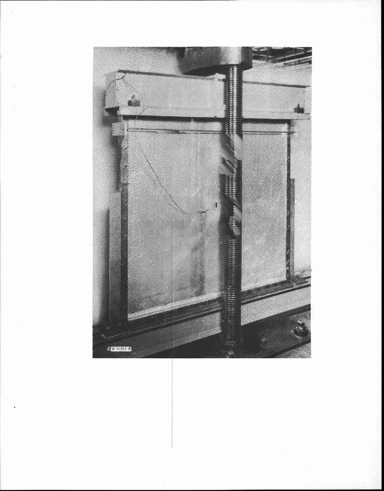
3 Edgewise Compressive Strength of Sandwich Panels Experimental work was done to determine the buckling load and the maximum load of flat panels of sandwich constructions loaded in uniform edgewise compression. The edges of the panels were simply supported insofar as practicable. Materials The sandwich constructions were of every possible combination of , , and inch facings of clad 21ST aluminum sheets on 5/8-inchthick cores of either 4- or 8-ounce phenol-resin-impregnated cotton cloth formed to a honeycomb of 7/16-inch cell s ize. The 4- and 8-ounce cores had densities of 4.2 and 8.9 pounds. per cubic foot, respectively. Facings were bonded to the cores with a high-temperature-setting modified phenolpolyvinyl butyral adhesive. Two panels, 110 inches long - and 48 inches wide, were made of each construction. The aluminum facings were placed so that the direction of rolling was parallel to the long dimension of the panel. The core material was placed so that the continuous direction of the cloth was parallel to the long dimension of the panel. Three square panels, one V inches, one 37-1/2 inches, and one 19-3/4 inches in size were cut from each large panel. Smaller coupons for determining the moduli of rigidity of the cores were also cut from,each large panel. The square panels were prepared for testing by bonding 1-inch Strips. of inch-thick aluminum to each facing at the loaded ends to prevent local facing failures. These strips were bonded with a contact-pressure,., room-temperature-setting epichlorohydrin resin-base, adhesive that had been developed at the Forest Products Laboratory for the Bureau of Aeronautics, U. S. Navy.. Testing The square sandwich panels were tested in edgewise compression in the apparatus shown in figure 1. The ends of the panel were loaded through flat steel bars. The vertical edges were simply supported in narrow, adjustable slots. A detailed sketch of these edge supports is shown in figure 2. Panels calculated to fail at loads less than 100,000 pounds were tested in a hydraulic testing machine. Stronger panels were, tested in a mechanically operated testing machine of larger capacity. The loads were applied at a free-head travel of the movable head of the testing machine of approximately 0.02 inch per minute. Strains at the panel center and in a direction parallel to the direction of the applied. load were measured on each facing by means of metalectric strain gages. Small strips of sandwich constructions cut from the same large panels as were the compression specimens were tested in bending under center loading over a relatively short span to determine the moduli of rigidity of the core materials. Strips were cut both parallel and perpendicular to the long dimension of the large panel so that the modulus could be measured Rept. No

4 both parallel and perpendicular to the continuous direction of the cloth of the core. The method used to calculate the moduli of rigidity is given in the appendix to this report. Values of the moduli are given in table 1. Results of Tests Approximately 60 percent of the compression panels exhibited definite buckling. Many of these panels showed large buckles, but the stiffer one did not have much of a buckled appearance. The exact determination of the buckling loads was made by observing the load-strain curves. The buckling load was that load at which one of the facing strains began to decrease. An illustration of this is given in figure 3. The facing stresses at buckling for the various panels are given in table 1. Behavior after buckling was characterized by increasing deflection of the buckled surface and finally resulted in failure by crimping, often near one end of the panel. There was usually not much increase in load at failure compared to the buckling load. This is shown by the graph of figure 4, in which the facing stress at failure is compared with the stress at buckling. The stresses were obtained by dividing the load by loaded area of the facings. The greatest panel load was approximately 20 percent larger than the buckling load of that panel. Maximum facing stresses for all the panels are given in table 1. Analysis and Discussion of Test Results The behavior of the edgewise compression specimens suggested a comparison of the experimental buckling stresses with stresses computed by means of formulas obtained from a theoretical analysis3 of the compressive buckling of sandwich construction. Although buckling was not evident in many of the specimens tested, the failure was sudden and of the same type as for specimens that definitely did buckle, and since it thus indicated buckling, the buckling stresses were computed for all specimens. The facing stresses for sandwich-panel buckling for constructions having isotropic facings on orthotropic cores, with all edges simply supported, are given by:2 P f =,2 2 2 f f (h + c) b E K + 1'2 ) 2 n2 1+ \2 n 2a b2) 2 c f1f2 a2k ( f f ) 1 2 E n2a2e Ga b2g b -This analysis was obtained from equations 1, 11, and Bll of Forest Products Laboratory Rept. No B, "Compressive Buckling of Sandwich Panels Having Facings of Unequal Thickness," by W. S. Ericksen and H. W. March. Nov ( 1) Rept. No

5 where pf = facing stress fl, f 2 = facing thicknesses h = total sandwich thickness c = core thickness a panel width (loaded edge) b = panel length n =,number of half waves in buckled form n = 1, 2, 3, Note: "n" is chosen so that pf is minimum E = facing modulus of elasticity A = G.91 G a core shear modulus associated with shear in the direction of dimension "a" Gb = core shear modulus associated with shear in the direction of dimension "b" In order to determine stresses greater than the proportional limit value the tangent modulus ET was used in equation 1. The condition then remained that the modulus must be compatible with the stress. This was easily accomplished by taking the reciprocal of equation 1 and multiplying by the Young's modulus. The resulting expression is: -5; =Q + U (2) where Q- L 4,.2 2 4X a kfi. + f2) n 77 2 fif2 b2 (h c)2 n2a2 2 b2 U- f 2 2 G b 4ca2 (f +JL) (11-- a + 1 b 2 G a n 2 E b2 (h + c) n2a2 G b2 // b E = Young's modulus of facings ET = tangent modulus Rept. No


6 Expression 2 was solved graphically by placing a straight line of slope Q and ordinate intercept U on a reciprocal stress-modulus curve. The point of intersection of the straight line with the curve gave the appropriate value of,which was then divided into the Young's modulus to obtain the Pf facing stress at panel buckling. A reciprocal stress-modulus curve and an example of its application are given in figure 5. Facing stresses at the panel buckling loads were theoretically computed by using equation 2 for the various constructions tested. Values of n were chosen so that the stress was a minimum, and it was found that for the panels tested n = 1 always gave the minimum stress. The computed stresses are given in table 1. A graphical comparison of the computed stresses with the test buckling stresses is made in figure 6. The maximum test stresses were compared with the computed buckling stresses for panels that did not exhibit definite buckling. The comparison made in figure 6 shows that, on the average, the test panels buckled at stresses somewhat greater (approximately 15 percent) than were theoretically computed. The buckling stress obtained from the tests was no doubt influenced by the end conditions of the specimen. These ends were flat rather than simply supported, and buckling stresses greater than the computed values would therefore be expected. Figure 6 shows that there was considerable scatter of the individual test points, approximately +30 percent, from theoretical values. This scatter is not unreasonable for the stability type of behavior. Conclusions The theoretical analysis employed yields reasonable estimates of the buckling stresses of simply supported flat panels of sandwich construction under edgewise compression. The strength of flat sandwich panels under edgewise compression loads may be considered to be the buckling load. Flatwise Flexural Strengths of Strips of Sandwich Construction Flexure tests were conducted by loading flat sandwich strips with two symmetrical, concentrated loads. The greater part of the work was done on relatively long specimens chosen so as to fail in the facings rather than in the core. Materials The strips of sandwich construction were of every possible combination of of , , and inch facings of clad 24-ST aluminum sheets on Rept. No. 1827
 4-ounce phenol-resin-impregnated cotton cloth formed to 7/16-inch cell size; density of 4.2 pounds per cubic foot.")
7 each of the following 1-inch-thick honeycomb cores placed so that the continuous direction of the sheet material of the core was parallel and also perpendicular to the span. (1) 4-ounce phenol-resin-impregnated cotton cloth formed to 7/16-inch cell size; density of 4.2 pounds per cubic foot. (2) 8-ounce phenol-resin-impregnated cotton cloth formed to 7/16-inch cell size; density of 8.9 pounds per cubic foot. (3) 3-mil 3SH aluminum sheet formed to 3/8-inch cell size; density of 4.2 pounds per cubic foot. (4) 5-mil 3SH aluminum sheet formed to 3/8-inch cell size; density of 6.5 pounds per cubic foot. (5) 2-mil 3SH aluminum sheet formed to 1/4-inch cell size; density of 4.2 pounds per cubic foot. - (6) 4-mil 3SH aluminum sheet formed to 1/4-inch cell size; density of 7.5 pounds per cubic foot. Facings were bonded to the cores with a high-temperature-setting phenolpolyvinyl butyral adhesive. Large panels of these constructions were furnished, and flexure specimens 2 inches wide were cut from them wiya t a metal-cutting band saw. Additional specimens were cut of constructions ave unequal facings so that tests could be made with the thin facing in compression and also in tension. Testing The flexure specimens were loaded at two points, each 2 inches from the midspan point. The loading points,had a radius of approximately 1/16 inch in contact with a 1/8-inch-thick piece of birch plywood extending 1/2 inch from each side of the load point. The plywood was placed between the loaded facing and the load point to eliminate failures due to highly concentrated stresses. The specimens were supported at the reactions on plates separated by rollers. The total thickness of the rollers and plates was approximately 1/2 inch. The lower plate was free to tilt on the knife-edge reaction support. Central deflections were measured by observing the movement of a scale, reading to 0.01 inch, suspended on a pin at, the center of the core with respect to a fine wire stretched from pins placed at the core center at the reactions. The wire was held taut by means of a stretched rubber band at one end. The angle of slope of the beam at one reaction was measured by observing the tilt of a protractor that was fastened to the bottom surface of the reaction plate. Tests were first made on constructions having the thickest facings on short spans (12 in.) for all core materials in order to obtain the core shearing strengths. Long specimens were then designed to fail in the facings if possible. Rept. No. 1827

8 Results of Tests A total of 200 tests were made. Of this number 36 were short so as to insure shearing failure in the core. The remaining specimens were longer and should have failed in the compression or tension facing. Of these remaining specimens 35 percent of them failed in the compression facing, 17 percent in the tension facing, 10 percent in shear in the core, and 38 percent failed in the bond between the facing and core. The construction descriptions, together with maximum loads, deflections, end slopes, and types of failure are given in table 2. The maximum moment is also given. This was computed from the formula: M = Pka PA tan 2 where M = maximum moment ( 3 ) P total load ka = distance from reaction to load point A = midspan deflection O slope of beam at reaction The derivation of expression 3 may be seen by referring to sketch A of figure 7. It was observed that the compression facing failures begun by the facing dimpling into the open cells of the honeycomb cores. This dimpling grew so prominent that the entire core pattern was visible over the central portion of the specimen. Final failure usually occurred by sudden separation of the facing from the core. Tension facing failures occurred only in specimens having tension facings thinner than compression facings. The failure was sudden and usually broke straight across the specimen and was always located between the load points. The midspan deflection-at failure was usually 3 to 6 times greater at tension failure than for compression failure of the same construction with the thin facing in compression. Shear failures in the cores occurred suddenly and were evidenced by buckling of the honeycomb cell walls, followed by a crimping appearance of the sandwich at the point of severest failure. Bond failures occurred by sudden separation of the facings from the core. Usually this separation extended from a load point to the adjacent reaction. Occasionally there was some core failure in conjunction with the bond failure, although it was not apparent as to whether the core failure occurred with or immediately after the bond failure. Approximately one-half of the bond failures occurred at core shear stresses far less than the shearing strengths of the cores. Rept. No

9 Analysis and Discussion of Test Results The following analysis and discussion is divided into two parts, first, the failure of facings, and second, the failure of cores and bonds. A tabulation, was made of the tension facing failures. It compression failure could be cores of different honeycomb for the different cell sizes puted by using the formula: maximum moments that caused compression or was noticed that the moment necessary to cause segregated into parts representing sandwich cell size. Values of the moments are given in table 3, AveragefaOing stresses were com- 2M f (h + c) 12 P f (4) where pf = average facing stress M = moment f = facing thickness h = total sandwich thickness c = core thickness This formula was obtained by equating the moment, M, to the couple formed by the facing forces, F, acting at a distance h C apart (fig. 7, B). 2 A comparison of the facing Stresses given in table 3 shows that for compression failures these stresses increase as the core cell size decreases and as the facing thickness increases, and that for tension failures the stresses are approximately the same regardless of core cell size or of facing thickness. The tension facings failed at an average stress of 63,200 pounds per square inch as compared to a tensile strength' of 24-ST clad aluminum of 64,000 pounds per square inch._ Since it was observed that the compression facings showed dimpling into the honeycomb core cells, the compressive stress at dimpling was calculated by the forraula:z 4 -Ibis value was given in the booklet, "Alcoa Aluminum and Its Alloys," by Aluminum Company of America. -Norris, C. B., and Kommers, W. J. Short-column Compressive Strength of Sandwich Constructions as Affected by the Size of the Cells of Honeycomb-core Materials. Forest Products Laboratory Rept. No. 1817, Aug Rept. No
 3/2 E 1 Ft (6) where E = Young's modulus of the facing material.")
10 3/2 1, Pf 5 (r12") (5) where pf = facing stress at dimpling ER = reduced facing modulus fl = compression facing thickness R = radius of circle inscribed in core cell This formula was simpler to use at stresses greater than the proportional limit by inverting it and multiplying both sides by the Young's modulus; then = 3.33 R ) 3/2 E 1 Ft (6) where E = Young's modulus of the facing material. Equation (6) was solved graphically by use of a reciprocal stress-modulus curve. A curve for the facings tested is given in figure 5. Theoretical dimpling stresses for the compression facings were computed for the various cell sizes by using equation (6) and the graph of figure 5. A comparison was made by plotting the experimental stresses versus the computed values in figure 8. The experimental values agreed with +12 percent of the computed values. Core failures and bond failures of sandwich beams in flexure are essentially shear failures. Therefore the core shearing stresses were computed for specimens failing in shear or bond by using the formula: (7) where = shearing stress P = total load supported by the beam h = total sandwich thickness c = core thickness The values obtained are given in table 2. The core shear stress developed at shear or bond failure is plotted versus the shear strength of the appropriate core, as obtained by testing short specimens with thick facings, in figure 9. The points on this figure show that shearing failures occurred Rept. No

11 in some of the longer specimens at stresses of approximately 75 percent of the shearing-strength values. This seemed to be independent of facing thickness, as can be observed by comparing values in table 2. Since the core material may have been of changeable quality, the comparison should not be made, but the strength of the core would probably be an average of values obtained for all spans. Half of the bond failures occurred at core shearing stresses within approximately 30 percent of the core shear strengths. The remaining bond failures occurred at much lower stresses, one as low as 10 percent of the core shear strength. The low-strength bond failures were probably due to defects that might easily occur during the experimental manufacture of sandwich panels. A more rigid control of processes, such as would be necessary for quantity production, would help considerably to produce consistently good-quality panels. Conclusions The following conclusions preclude the possibility of failures due to low bond strengths or defects. Tension facing failures of sandwich construction occur at the tensile strength of the facing. Compression facing failures of sandwich constructions having honeycomb cores occur at the stress at which the facing buckles into the cells. Shearing failures occur at the shear strength of the core material. The preceding conclusions combined,with ordinary design considerations for beams enable the designer to predict the behavior of loaded beams of sandwich construction. Rept. No

12 Appendix Method for Determining Core Moduli of Rigidity The deflection of a strip of sandwich construction in flexure results from the combined action of bending moments and shearing forces, The deflection caused by bending moments varies as the cube of the span length and the deflection caused by shear varies linearly as the span length; therefore, the shearing deflection will be a greater percentage of the total deflection if the span length is shortened. Theoretical formulashave been derived for the bending and the shearing deflections.- By solving these formulas for the shear modulus of the core material, the results of tests on a centrally loaded beam may be used to calculate this core modulus. The formula is given by: G = Pax, 2 6h (h + c)b 11 -, ) /40AD (Al) where G = core shear modulus P "4-7 central concentrated load a = span length c = core thickness = central deflection at load P h = total sandwich thickness b = width of sandvich bf,fo(h + c) 2 E D = ` 4 (h c) X f 12 = facing thicknesses, E = facing modulus of elasticity X = 0.91 The value of ' a3 48.\D necessary. was kept less than 0.60 by shortening the span if March, H. W., and Smith, C. B. "Flexural Rigidity of a Rectangular Strip of Sandwich Construction." Forest Products Laboratory Rept. No. 1505, Rept. No


13 Table L.--Results of tests of sandwich panels in edgewise compressioii... :. : : Panel: Facing : Total : Width:Length: Shear moduli :Weight: Test facing : Computed No. : thickness :thick- : : of : stresses : buckling : ness : : cloth: : stress : : :.---: in :Buckling:Maximum : fl : f2 : h : a 1 b Gb : Ga : core : stress : stress : : : : : : : Per : %ex : : : In. : In. : In. : In. : In. : P.s.i. : P.s.i.: Oz. : P.s.i. : P.s.i. : P.s.i. C la : : : : 46.5 : 46.5 : 5,66o 1 2,820 : 4 : 21,800 : 26,200 : 18,500 b :.020 :.020 :.673 : 46.5 : 46.5 : 5,980 : 2,580 : 4 : 22,300 : 26,400 : 18,200 C 2a :.020 :.020 :.671 : 37.0 : 37.0 : 5,660 : 2, : 20,000 : 20,700 : 26,500 b :.020:.020:.671 : 37.0 : 37.0 : 5,980 : 2,580: 4 : 31,300 : 33,400 : 26,200 'C 5a :.020:.020:.671 : 19.5 : 19.5 : 5,660 : 2,820: 4 41,300 : 36,800 b :.020 :.020 :.670 : 19.5 : 19.5 : 5,980 2,580 : k- 40,200 : 36,500 c 4a :.020 :.020 :.665 : 46.5 : 46.5 : 10,190 : 4,580 : 8 : 21,200 : 25,900 : 18,900 b :.020 :.020 :.672 : 46.5 : 46.5 : 10,460 : 4, ,800 : 27,300 : 19,400 C 5a :.020 :.020 :.662 : 37.0 : 37.0 : 10,190 : 4,380 : 8 : 31,300 : 34,500 : 27,300 b :.020 :.020 :.674 : 37.0 : 37.0 : 10,460 : 4,960 : 8 C 6a :.020 :.020 :.664 : 19.5 : ,190 : 4,380 : 8 42,400:: 27,90 b :.020 :.020 :.672 : 19.5 : 19.5 : 10,460 : 4,960 : 8 42,200 : 38,200 C 7a :.040 :.040 :.711 : 46.5 : 46.5 : 6,390 : 2,540 : 4 : 20,200 : 22,300 : 16,600 b :.040:.040 :.716 : 46.5 : 46.5 : 6,960 : 2,110 : 4 : 19,100 : 22,300 : 16,400 C 8a. :.040:.040:.713 : 37.0 : 37.0 : 6,390 : 2,540: 4 : 25,000 : 23,000 : 23,000 b : 040 :.040 :.709 : 37.0 : 37.0 : 6,960 : 2,110 : 4 27, 000 : 21,700 C 9a :.040 :.040 :.711 : ,390 : 2,540 : 4 35, ,000 b :.040 :.040 :.712 : 19.5 : 19.5 : 6,960 : 2,110 : 4 32,400 : 33,300 ClOa :.040:.040 :.711 : 46.5 : 46.5 : 8,670 : 4,120: 8 : 20,700 : 23,700 : 18,100 b : :.711 : 46.5 : 46.5 : 10,390 : 4, ,100 : 22,600 : 18,900 Clia :.040:.040 :.710 : 37.0 : 57.0 : 8,670 : 4,120: 8 : 25,300 : 27,900 : 25,800 b :.040 :.040 :.713 : 37.0 : 37.0 : 10,390 : 4,990 : 8 : 28,000 : 30,000 : 27,000 C12a : :.711 : 19.5 : 19.5 : 8,670 ; 4,120 : 8 37,900 : 36,400 b :.040 :.040:.714 : 19.5 : 19.5 : 10,390 : 4, ,200 : 37,200 C13a :.064 :.064 :.759 : 46.5 : 46.5 : 6,490 : 2,720 : 4 : 17,300 : 20,400 : 15,900 b :.064 :.064 :.759 : 46.5 : 46.5 : 6,630 : 2,460 : 4 : 17,300 : 19,400 : 15, a :.064:.064 :.758 : 37.0 : 37.0 : 6,490 : 2,720 : 4 : 22,100 : 23,400 : 20,700 b :.064 :.064 :.758 : 37.0 : 37.0 : 6,630 : 2, ,500 : 20,100 C15a :.064:.064 :.758 : 19.5 : 19.5 : 6,490 : 2,720 : 4 25,500 : 31,200 b :.064 :.064 :.759 : 19.5 : 19.5 : 6,630 : 2,460 : 4 25,400 : 30,600 c16a :.064 : : 46.5 : 46.5 : 9,820 : 4, ,900 : 22,600 : 18,100 b :.064 :.064 :.755 : 46.5 : 46.5 : 10,010 : 4,490 : 8 : 20,200 : 22,600 : 18,200 C17a :.064 :.064 :.758 : 37.0 : 37.0 : 9,820 : 4,510 : 8 : 23,300 : 24,200 : 24,700 b :.064:.064:.754 : 37.0 : 37.0 : 10,010 : 4,490 : 25,800 : 28,200 : 24,900 Cl8a :.064 :.064 :.757 : 19.5 : 19.5 : 9,820 : 4,510: 8 : 31,500 : 32,100C: 35,300 b :.064 :.064 :.758 : 19.5 : 19.5 : : 4,490 : 8 22,800 : 35,300 Z F Sheet 1 of 2


14 ' Table 1.--Results of tests of sandwich panels in edgewise compression) (Continued) Panel: Facing : Total : Width:Length: Shear moduli :Weight: Test facing : Computed No. : thickness : thick-: : : : of : stresses : buckling : ness : : : : cloth: : stress : : in :Buckling:Maximum : Pi : r2 :/1:a:b: Gb! Ga : core : stress : stress :. : : : Pcr Pima : : : : : : 1 : : In. : In. : In. : In. : In. : P.s.i. : P.s.i.: Oz. : P.s.i. : P.s.i. :JP.s.i. Cl9a : : : : 46.5 : 46.5 : 6,260 : 2,350 : 4 : 21,300 : 23,900 : 15,500 b :.020 :.040 :.684 : 46.5 : 46.5 : 6,610 : 2,570 : 4 : 18,400 : 21,000 : 15,600 C20a :.020 :.040 :.691 : 37.0 : 37.0 : 6,260 : 2,350 : 4 : 16,400 : 18,500 : 22,100 b :.020 :.040 :.683 : 37.0 : ,610 : 2,570 : 4 : 28,000 : 29,300 : 22,100 C21a :.020:.040 :.689 : 19.5 : 19.5 : 6,260 : 2,350: 4 t 39,100 : 34,200 b :.020:.040:.698 : 19.5 : 19.5: 6,610 : 2,570: 4 37,100 : 35, a :.020 :.040 :.691 : 46.5 : 46.5 : 10,140 : 4,75o 8 23,700 : 26,500 : 17,200 b :.020:.040:.690: 1#6.5:46.5: i0,180:14,420: 8 : 19,800 : 22,500 : 17,100 C23a :.020:.040:.693 : 37.0 : 37.0 : 10,140 : : 8. 27,700 : 25,800 b :.020:.040:.692 : 37.0 : 37.0 : 10,180 : 4,420 : 8 : 29,300 : 31,900 : 25,400 C24a :.020:.040:.694 : 19.5 : 19.5 : 10,140 : 4,750: 8 40,800 : 36,800 b :.020 :.040 :.709 : 19.5 : 19.5 : 10,180 : 4,420 : 8 37,600 : 37,000 C25a :.040 :.064 :.730 : 46.5 : 46.5 : 6,360 : 2, : 15,500 : 17,800 : 15,700 b :.040:.064:.726 : 46.5 : 46.5 : 5,370 : 2,93o : 4 : 15,900 : 17,000 : 15,300 C26a :.040 :.064 :.729 : 37.0 : 37.0 : 6,360 : 2, ,400 : 21,400 b :.040:.064:.727 : 37.0 : 37.0 : 5,370 : 2,930: 4 : 18,500 : 19,500 : 20,800 C27a :.040 : : 19.5 : 19.5 : 6,360 : 2,930 : 4 28,100 : 32,800 b :.040:.064 :.729 : 19.5 : 19.5 : 5,370 : 2,930: 4 30,000 : 32,300 C28a :.040:.064:.734 : 46.5 : 46.5: 9,950 : 4,770: 8 : 18,000 : 21,200 : 17,800 b :.040 :.064 :.732 : 46.5 : ,350 : 4, : 16,800 : 20,200 : 17,610 C29a :.040 :.064 :.734 : 37.o : 37.0 : 9,950 : 4,770 : 8 : 28,200 : 30,100 : 25,300 b :.040 :.064 :.730 : 37.0 : 37.0 : 9,350 : 4,66o : 8 : 27,100 : 28,600 : 24,700 C30a :.040 : : 19.5 : 19.5 : 9,95o : 4,770 : 8 29,500 36,000 b :.040 :.064 :.732 : 19.5 : 19.5 : 9,350 : 4,664 : 8 37,800 : 35,700 C31a :.020 :.064 :.709 : 46.5 : ,260 : 2,490 : 4 : 16,700 : 19,300 : 12,800 b :.020 :.064 :.712 : 46.5 : 46.5 : 5,890 : 2,480 : 4 : 15,200 : 17,400 : 12,800 C32a :.020 :.064 :.709 : 37.0 : 37.0 : 6,260 : 2,490 : 4 : 19,000 : 24,100 : 17,900 b :.020 :.064 :.710 : 37.0 : 37.0 : 5,890 : 2,480 : 4 : 22,200 : 23,600 : 17,900 C33a :.020 :.06 :.709 : 19.5 : 19.5 : 6,260 : 2,490: 4 34,100 : 31,600 b :.020 :.064 :. 712 : 19.5 : 19.5: 5,894 : 2,480: 4 : 56,100 : 36,700 : 31,500 C34a :.020 :.064 :.709 : 46.5 : 46.5 : 10,85o : 4,720 : 8 : 15,700 : 17,500 : 14,100 b :.020 :.064 :.711 : 46.5 : 46.5 : 10,930 : 5,470 : 8 : 15,700 : 18,000 : 14,400 C35a :.020 :.064 :.708 : 37.0 : 37.0 : 10,850 : 4,720 : 8 : 22,200 : 24,700 : 20,700 b :.020 : : 37.0 : 37.0 : 10,930 5,470 : 8 : 24,100 : 26,200 : 20,900 C36a :.020:.064:.709 : 19.5 : 19.5 : 10,850 : 4,720 : 8 30,000 ; 34,500 b--:.020 :.064 :.694 : 19.5 : 19.5 : 10,930 5,470 : 8 37,600 : 34,200 1-Facings of 24 ST clad aluminum, cores of'impregnated-cotton-cloth 7/16-inch-cell-size honeycomb. Sheet 2 of 2 Z M F


15 Table 2.--Results of flexure tests of sandwich constructions having facings of 24 ST clad aluminum. Loads applied 2 inches each side of midspan Spec-: Thickness.:Span: Maximum Failure : Maximum imen : : : : : core No. :Compres-:Tension: Total : : Load : Center,: Slope : Moment : : shear sion : facing: : :per inch:deflec-: at :per inch: : stress : facing : : : : width : tion :reaction: width : fl : f2 : h : a :P : A o m: r... 1 : In. : In. : In. : In.: Lb. : In. : Deg. :In.-lb. : : P.a./. Core: 4-ounce cotton-cloth honeycomb; parallel to span B la : : : : 18 : 219 : 0.38 : 3.0 : 768 :Compression. b :.020 :.020 : : 18 : : 3.0 : 711 do B 4a :.020 :.040 : : 18 : : 2.0 : 739 do b :.020 :.040 : : 18 : : do c :.040 :.020 : : 18 : ,143 : Shear : 158 d :.040 :.020 : : 18 : : 5.0 : 1,091 do 151 B 5a :.020 :.064 : : 18 : : 2.0 : 774 :Compression b :.020 :.064 : : 18 : : 2.0 : 763 do c :.064 :.020 : : 18 : : 2.5, : 1,024 : Shear : 141 d :.064 :.020 : : 18 : : 2.0 : 897 do 123 B 3a :.064 :.064 : : 12 : 310 do 146 b :.064 :.064 : : 12 : 322 do 151 c :.064 :.064 : : 12 : 305 do 143 Core: 4-ounce cotton-cloth honeycomb; perpendicular to span B la :.020 :.020 : : 20 : 120 :.36 : 2.0 : 478 : Shear : 59 B 3a :.064 :.064 : : 12 : 145 do 68 b.064 :.064 : : 12 : 170 do c :.064 ;.064 : : 12 : 160. do Core: 8-ounce cotton-cloth honeycomb; parallel to span B 7a :.020 :.020 : : : 2.0 : 766 :Compression b :.020 :.020 : : 12 : : 4.5 : 778 do B 8a :.040 :.040 : 1,095 : 20 : : 3.5 : 1,498 : Bond : 178 b :.040 :.040 : : 20 : : 4.5 : 1,901 do 224 B 9a :.064 :.064 : : 28 : 529 : 1.30 : 5.5 : 3,204 do 246 b :.064 :.064 : : 28 : 559 : 1.35 : 6.5 : 3,372 do 261 BlOa :.020 :.040 : : 20 : : 2.5 : 912 :Compression b :.020 :.040 : : 20 : 215 :.32 : 2.5 : 862 do c :.040 :.020 : : 20 : 305 : 1.59 : 11.5 : 1,270 : Tension d :.040 :.020 : : 20 : 309 : : 1,289 do Blla :.020 :.064 : : 28 : : 2.5 : 785 :Compression b :.020 :.064 : : 28 : : 2.5 : 821 do c :.064 :.020 : : 28 : 208 : 1.90 : 9.5 : 1,287 : Tension d :.064 :.020 : : 28 : 218 : 2.79 : 14.5 : 1,389 do B12a :.040 :.064 : : 25 : 435 : 1.02 : 6.0 : 2,279 :Compression b :.040 :.064 : : 25 : 416 :.93 : 5.0 : 2,212 do c :.064 : ;040 : : 25 : 494 : 1:58 : 14.5 : 2,678 : Bond : 233. d :.064 :.040 : : 25 : 489 : 2.19: 12.0 : 2,685 do 230 Z M F Sheet 1 of 6
 Spec-: Thickness :Span: Maximum : Failure : Maximum mien: : : : : core No.")
 B 9a : 0.064 : 0.064 : 1.")
16 Table 2.-..Results of flexure tests of sandwich constructions having facings of 24 $T clad aluminum. Loads applied 2 inches each side of midspan (ContiAmed) Spec-: Thickness :Span: Maximum : Failure : Maximum mien: : : : : core No. :Compres-:Tension: Total : : Load : Center: Slope : Moment : : shear : slam : facing: : :per inch:deflec- I: at :per inch: : stress : facing : : : : width : tion 1:reaction: width : : f 1 : f2 :h:a:p : A 0 M : 1 I"- : In. : In. : In.. : In.: Lb. : In. : Deg. :In.-lb. : : P.s.i. Core: 8-ounce cotton-cloth honeycomb; parallel to span (Continued) B 9a : : : : 12 : 622 Shear : 292 b :.064 :.064 : : 12 : 065 do 266 c :.064 :.064 : : 12 : -600 do 282 Core: 8-ounce cotton-cloth honeycomb; perpendicular to span B 7a :.020 :.020 : : 12 : :' : 447 :Compression. b :.020 :.020 : : 12 : : 1.5 : 402 do B 8a :.040 :.040 : : 20 : 260 :.43 : 2.5 : 1,046 : Bond : 124 b:.040 :.040 : : 20 : ': 2.5 : 1,064 do 127 B 9a :.064 :.064 : : 28 : : 2.0 : 1,449 do 113 b :.064 :.064 : : 28 : : 1.5 : 1,261 do 98 BlOa :.020 :.040 : : 20 : : 3.0 : 727 :Compression. b :.020 :.040 : : : 4.0 : do c :.040 -:.020 : : 20 : : 2.0 : 819 : Bond : 98 d :.040 :.020 : : 20 : : 2.5 : 802 do 98 Blla :.020 :.064 : : 25 : : 2.0 : 812 :Compression. b :.020 :.064 : : 25 : : 2.0 : 805 do c :.064 :.020 : : 25 : 228 : 2.64 : 14.0 : 1,272 : Tension :.064 :.020 : : 25 : 222 : 2.14 : 11.5 : 1,215 do B12a :.040 :.064 : : 28 : : 3.5 : 1,417 : Bond : 112 b :.040 :.064 : : 28 : : 4.0 : 1,626 do 128 c :.064 :.o4o : : 28 : : 3.5 : 1,599 do 125 d :.064 :.040 : : 28 : 253 :.77 : 3.0 : 1,517 do 119 B 9a :.064 :.064 : : 12 : 350 Shear : 164 b :.064 :.064 : : 12 : 330 do 155 c :.064 :.064 : : 12 : 360 do Core: Aluminum honeycomb, 3/8-inch cell size of inch 3SH foil; oarwel to span B13a :.020 :.020 : : 12 : 334 :.13 : 2.0 : 666 :Compression. b :.020 :.020 : : 12 : 410 :.13 : 2.0 : 820 do B14a :.040 :.040 : : 20 : 395 :.31 : 2.0 : 1,586 : Bond : 189 b :.040 :.040 : : 20 : 193 :.18 : 1.5 : 772 do - 92 B15a :.064 :.064 : : 28 : : 3.5 : 2,352 do 181 b :.064 :.064 : : 28 : : 3.0 : 2,078 do 158 B16a :.020 :.040 : : 20 : 222 :.37 : 2.0 : 882 :Compression - b :.020 :.040 : : 20 : 214 :.30 : 2.5 : 859 do c :.040 :..020 : : 20 : 303 : 1.40 : 9.0 : 1,246 : Tension d :.040 :.020 : : 20 : 293 : 1.10 : 8.0 : 1,194 do z M F Sheet 2 of 6

 B17a : 0.020 : 0.064 : 1.083 : 25 : 150 : 0.29 : 2.0 : 796 :Compression b :.020 :.064 : 1.084 : 25 : 150 :.")
17 Table 2.--Results of flexure tests of sandwich constructions having facings of 24 ST clad aluminum. Loads applied 2 inches each side of addspan (Continued).. :. Spec-:.Thickness :Span: Maximum : 'Failure : Maximum imen :. : : : core No. :Compres-:Tension: Total : : Load : Center!: Slope : Moment : : shear Sion : facing: : :per inch:deflec-1: at :per inch: : stress facing : :' : width : tion :reaction:.width : fl : f2 :h:a:p : 6 :0 M 1 T'' Lb. In. L In. : In. : In. : In. : Rya :In.-lb. : : P.s.i. Core: Aluminum honeytomb1. 3/8-inch cell size of inch 32E foil; parallel to span (Continued) B17a : : : : 25 : 150 : 0.29 : 2.0 : 796 :Compression b :.020 :.064 : : 25 : 150 :.31 : 2.0 : 795 do c :.064 :.020 : : 25 : 235 : 1.76 : 10.0 : 1,289 : Tension d :.064 :.020 : : 25 : 180 :.36 : 2.5 : 1,218 : Bond : 86 B18a :.040 :.064 : : 25 : 406 :.86 : 5.0 : 2,158 do 193 b :.040 :.064 : : 25 : 400 :.79 : 4.5 : 2,116 do 190 c :.064 :.040 : : 25 : 385 :.51 : 3.5 : 2,033 do 182 d :.064 :.040 : : 25 : 320 :.39 : 2.5 : 1,687 do 152 B15a :.064 :.064 : : 12 : 502. Shear : 237 b :.064 :.064 : : 12 : 505 :...do c :.064 :.064 : : 12 : 455 do 214 Core: Aluminum honeycomb, 3/8-inch cell size of inch 3SH foil; perpendicular to span B15a :.064 :.064 : : 12 : 205 t Shear : 96 b :.064 :.064 : : 12 : 280,, do 132 c :.064 :.064 : : 12 : 252 do 118 Core: Aluminum honeycomb, 3/8-inch cell size of inch 3SH foil; parallel to span B19a :.020 :.020 : : 12 : 430 :.20 : 2.5 : 864 :Compressionb :.020 :.020 : : 12 : 395 :.18 : 2.0 : 785 do B20a :.040 : 0640 : : 20 : 582 : 1.69 : 13.0 : 2,436 : pond : 280 b :.040 :,.040 : : 20 : 584 : 1.77 : 13.0 : 2,452 :Compession B21a :.064 :.064 : : 28 : 275 :.34 : 2.0 : 1,681 :, Bond : 128 b :.064 :.064 : : 28 : 328 :.41 : 2.5 : 2,000 do ' 153 B22a :.020 :.040 : : 20 : 207 :.39 : 3.5 : 830 :Compression b :.020 :.040 : : 20 : 217 :.39 : 3.0 : 870 do c :.040 :.020 : : 20 : 289 : 1.44 : 10.0 : 1,190 : Tension d :.040 :.020 : : 20 : 282 : 1.12 : 7.5 1,146 do B23a :.020 :.064 : : 28 : 159 :.61 : 3.5 : 958 :Compression b :.020 :.064 : : 28 : 152 :.55 : 3.0 : 914 do c :.064 : : 28 : 196 : 1.97 : 10.0 : 1,219 : Tension d.064 :.020 : : 28 : 201 : 2.11 : 11.5 : 1,257 do B24a :.040 : : 25 : 445 : 1.06 : 5.5 : 2,364 :Compression b :.040 :.064 : : 25 : 460 : 1.29 : 8,0 : 2,494 do c :.064 :.040 : : 25 : 498 : 2.63 : 15.5 : 2,807 : Tension d :.064 : : 25 : 350 :.41 : : 1,846 : Bond : 166 B21a :.064 :.064 : : 12 : 9J Shear : 442 b :.064 :.064 : : 12 : 685 do. 320 c :.064 :.664 : : 12 : 720 do. 336 Z If Sheet 3 of 6
 Spec-: Thickness :Span: Maximum : Failure : Maximum amen :. : core No.")

18 Table 2.--Results of flexure tests of sandwich constructions havin5 facings of 24 ST clad aluminum. Loads applied 2 inches each side of madspan (Continued) Spec-: Thickness :Span: Maximum : Failure : Maximum amen :. : core No. :Compres-:Tension: Total : : Load Centerl: Slope : Moment : : shear : sion : facing: : :per inch:deflec.,: at :per inch: : stress : facing : : : : width.: tion :reaction: width : : : fi : f 2 :h :a:p :A:0:. : r 1 : : : :. : : t In. : In. : In. : In..: Lb. : In. : Deg. :In.-lb : : P.s.i. Core: Aluminum honeycomb, 3/8-inch cell size of 0,005 inch 3SB foilkperpendicular to span B19a : : : : 12 : 320 : 0.13 : 1.5 : 640 : Bond : 157 b :.020 :.020 : : 12 : : 1.0 : 344 :Compression B20a :.040 :.040 : : 20 : 342 :.32 : 2.5 : 1,360 : Bond : 165 b :.040 :.040 : : 20 : 280 :.24 : 1.5 : 1,119 do 135 B21a :.064 :.064 : : 28 : 197 ;.28 : 1.5 : 1,198 do 92 b :.064 :.064 : : 28 : 330 :.48 : 2.5 : 2,006 do 153 B22a :.020 :.040 : : 20 : : 3.0 : 790 :Compression b :.020 :.040 : : 20 : : 1.5 : 761 do * c :.040 :.020 : : 20 : 270 : : 1,120 : Tension d :.040 :.020 : : 20 : 264 : 1.34: 10.0 : 1,086 do. B23a :.020 :.064 : : 25 : : 2.0 : 737 : Bond : 68 b :.020 :.064 : : 25 : : 2.0 -: 842 :Compression c :.064 :.920 : : 25 : 218 : 2.35 : 13.0 : 1,205 : Tension d : : : 25 : 211 : 1.66 : 9.5 : 1,146 - do 824a :.040 :.064 ::1.104 : 28 : : 2,145 : Bond t /68 b :.040 :.064 : : 28 : 360 :.86 : 5.0 : 2,166 do 171 c :.064 :.040 : : 28 : 396 : 2.09: 11.0 : 2,469 do 188 d :.064 :.040 : : 28 : 375 : 1.37 : 7.5 : 2,292. do 178 B21a :.064 :.064 : : 12 : Shear : 149 b :.064 :.064 : : 12 : 330 do 154 c :.064 :.064 : : 12 : do 179 Core: Aluminum honeycomb, 1/4-inch cell size of inch 38R foil;: parallel to span B25a :.020 :.020 : : 12 : 418 :.17 : 3.0 : 842 :Compression b :.020 :.020 : : 12 : 432 :.22 : 3.0 : 874 do ' B26a :.040 :.040 : : 20 : 452 :.41 : 3.0 : 1,815 : Shear b :.040 :.040 : : 20 : 460 :.46 : 3.5 : 1,844 : Bond : a :.064 :.064 : : 28 : 438 :.65 : 3.5 : 2,666 do 208 b :.064 :.064 : : 28 : 432 :.64 : 4.0 : 2,655 : do 204 B28a : : : 20 : 245 :.41 : 4.0 : 986 :Compression b :.020 :.040 : : 20 : 244 :.47 : 3.5 : 978 do - c :.040 :.020 : 1).052 : 20 : 288 : 1.24: 10.0 : 1,186 : Tension d :.040 :.020 : : 20 : 290 : 1.43 : 10.0 : 1,197 * do B29a :.020 :.064 : : 25 : 200 :.66 : 4.0 : 1,065 :Compression. b :.020 :.064 : : 25 : 199 :.64 : 4.0 :. 1,055 do c :.064 :.020 : : 25 : 249 f : 14.5 : 1,399 : Tension d :.020 :.064 : : 25 : 203 :.65 : 4.0 : 1,077 :Compression. z M y Sheet 4 of 6
 : : : Spec-: Thickness :Span: Maximum : Failure : Nhximum amen - : core No.")
 B30a : 0.040 0.064 : 1.094 25 : 380 0.")
19 Table 2.--Results of flexure tests of sandwich constructions having facings of 24 ST clad aluminum. Loads applied 2 inches each side of midspan (Continued) : : : Spec-: Thickness :Span: Maximum : Failure : Nhximum amen - : core No. :Compres-:Tension: Total Load : Center: Slope :, Moment shear sion : facing:.:per inch:deflec-1: at :per inch: stress facing : -. width tion :reaction:,width ; :..... f 1 f 2 h :a: P :6, ; 8 :.M : : 4f- In. : In. : In. In.: Lb. In. DeA :In.-lb. : P.s.i. Core: Aluminum. honeycomb, 1/4-inch cell size of inch 3SE foil; parallel to span (Continued) B30a : : : : 4.0 2,014 : b : : : 25 : 405 :.83 : 5.0 : 2,157 c : : : 25 : : 2,414 d :.064 :.040 : : 25 : 405 :.54 : 3.0 : 2,144? B27a : : : 12 : b : : 455 c.064 :.064 : :. 473 Bond 182 do 193 do do 192 Shear : 219 do 214 do 222 Core: Aluminum honeycomb, 1/4-inch cell size of inch 3SR foil;.perpendicular to span B25a :'1.027::'18:: 210 : Shear 103 b : do 97 B28a.020 :.040 : :.19 : 1.5 : 626 do 88 b : : do.-,88 C :.22 : do 104 d : : : do 87 B29a : 188 :.17 : do - 91 b : 18 : 196 : do 95 C : 198 : do 96 d :.064 : :.18 : do 92 B27a :.064 :.064 : do 115 _ b : '-`.70 do 126 c : do 140 Core: Aluminum honeycomb, 1/4-inch cell size of inch 3SE foils: parallel to span B31a.020 :.020: 1,052 : 12 : b.020 :.020': B32a :.040 : : 20 b.040 : : Or: B33a.064 : : b.064 : B34a.020 : b :.020 : PO,: c :.040 : ' : d ; B35a : : : 28 b : : C.064 :.020 -: d :.064 :.020 : : 28 : Z M F 402 :.15 : : : :.09 :.5 : , : , : , :-.61 : 5.o : 1, , : , , : , : , :. 4.0 : 1,251 : Bond : 196' :Compression Bond do 44 do 277 do 195 :Compression do Tension - : Bond 145 :Compression do :. Tension do Sheet 5 of 6
 Spec-: Thickness :Span: Maximum : Failure : Maximum imen :.- : : : : core No.")

20 Table 2.--Results of flexure tests of sandwich constructions having facings of 24 ST clad aluminum. Loads applied 2 inches each side of midspan (Continued) Spec-: Thickness :Span: Maximum : Failure : Maximum imen :.- : : : : core No. :Compres-:Tension: Total : : Load : Center; Slope, : Moment : : shear sion : facing: : :per inch:deflec-': at :per inch: : stress facing :. : : width : tion :reaction:, width :1 f : :h:a:p :A: 1 19 :M" :,- : In. : In. : In. : In.: Lb. : In. : Deg. :In.-1b. : : P.s.i. Core: Aluminum honeycomb, I/4-inch cell size of inch 3SH foil; parallel to span (Continued) B36a : : : : 28 : 432 : 2.03 : 11.5 : 2,704 :Compression b :.040 :.064 : : 28 : 431 : 1.98 : 11.0 : 2,696 do c :.064 :.040 : : 28 : 416.: 3.35 : 18.5 : 2,760 : Tension d :.064 :.040 : : 28 : 416 : 3.53 : 19.0 : 2,776 do B33a :.064 :.064 : : 12 : 980 Shear : 456 b :.064 :.064 : : 12 : 825 do 384 c :.064 :.064 : : 12 : 93o # do 432 Core: Aluminum honeycomb, 1/4-inch cell size of inch 3SK foil; perpendicular to span B31a :.020 :.020 : : 12 : : 1.5 : 681 :Compression b :.020 :.020 : : 12 : : 2.0 : 762 : Bond :.185 B32a :.040 :.040 : : 20 : : 1.5 : 1,037 do 123 b :.040 :.040 : : 20 : : :do B33a :.064 :.064 : : 28 : : 3.5 : 2, do 166 b :.064 :.064 : : 28 : : 1.0 : 956 do 75 B34a :.020 :.040 : : 20 : : 3.5 : 996 :Compression b :.020 :.040 : : 20 : 198 :.25 : 2.0 : 794 : Bond : 96 d :.040 :.020 : : 20 : 256 :.63 : 5.0 : 1,034 do 124 d :.040 :.020 : : 20 : 188 :.27 :2.5 : 753 do 91 B35a :.020 :.064 : : 25 : 182 :.59 : 3.0 : 969 :ComPreaslon' b :.020 :.064 : : 25 : 189 :.65 : 4.0 : 998 do c :.064 :.020 : : 25 : 220 : 2.86 : 16.0 : 1,250 : Tension d :.064 :.020 : : 25 : : 5.0 : 1,017 : Shear : 92 B36a :.040 :.064 : : 25 : 392 :.84 : 4.5 : 2,096 : Bond : 186 b :.040 :.064 : : 25 : 388 '..80 : 4.5do : 2, c :.064 :.040 : : 25 : : : 2,121 do 197 d :.064 :.040 : : 25 : : 1.5 : 741 do 70 B33a :.064 :.064 : : 12 : 485. Shear : 226 b :.064 :.064 : : 12 : 480 do 223 c :.064 :, '0364 : : 12 : 45o do 209 Z M Sheet 6 of 6
 d rt et ea O0 0.0 8 0 0 0 0 \"-I II rl AR 24 11 0 0 0.1 H - H r-1 H r-7 -n et (1-1 air a I C:i 11 0 H 1 0 IZI 1& 1 1[ a 44 o N 0 0.")

21 c ri! 94 grj O attiqq Ok r-i a 0 0 XI 1-1 %0 i c.) i n '. at 0 0 t*- r ' r-4 r-1 N J or or r a) - O 0 0 (LI ro to A O 1 r4-1, Ctsr\ A A R r4 r-1 O :4 9 4 Ve\ te\ N N N C.) N I. r.1* 14. rl v-z rl ;4 r-r o A 0 1 7n9 \ r-i 1=1 N CO " CO II r a) d rt et ea O "-I II rl AR H - H r-1 H r-7 -n et (1-1 air a I C:i 11 0 H 1 0 IZI 1& 1 1[ a 44 o N 0 0..c1 0 Q t---z N tc\ 1 ts-- CO CO OD Cs- r-1 0J01C11KNOIN O 51 9 ) or H r-i i-ii-i r-7 i-i.7 o-. O A H -I- WI i I o I Cta..* 0 0 sl --"., CO II il 49 ck.i. or r4 r-1 I-I H 44 O C) 0 N.1:1 to A 0 A ota 43, u-n rl S Ch H If A4 Va ONc0 O ' 4,4 8 CO 0 0\ 0 0 o a, al r-i V8 Z & Ch 8\ art rt IN O ri H H ri 1-I rl H H H CH A 0.0 H al -I* In. 0%, co 0 (iii 4 PC\ r4 r KN..* H co... a pm 4141 GO O q 0 N,0 O Xi C:$,c1 1-I 1-4 H 41 s VD O ta "...t:.: rral A a1'.) H 9.1 N al, d n 5.,, # :' raw va. oile S Il A o-41 r, -1-2 PI 0O cti ts- Mren CO H ON UN.* tev1/40 CO V LCY LIN.-I t V t.4. If\ 0 in 19g PPM11-r rola gml..v. gp g 14 I=1 c0 _ 1-4 Mi l) rjoi -N ci' 4' cila gi FA Pit\. / 72- UNGCD 10.- (114\ P' (:)19- rig I)- (D KC cuj a) 1 co 0 cc N a) pd IF\ t- os.1=1 X12 r1 i-i CD PI El cd 14y II 94 rl
22
23
24

25
26
27
28
29
30
ELASTIC STAIBILITY CIF TUE FACINGS Of HAT SANDWICI-1 PANELS WIASI SUBJECTED TO COMBINED EDGEWISE STRESSES
 ELASTIC STAIBILITY CIF TUE FACINGS Of HAT SANDWICI-1 PANELS WIASI SUBJECTED TO COMBINED EDGEWISE STRESSES Information Reviewed and Reaffirmed Aucust 1955 NFORMA-tiON RE'4,E\AE.'L; n PE.1-17;9';f2,. This!Report
FLEXURE OF STRUCTURAL SANDWICH CONSTRUCTION
 FLEXURE OF STRUCTURAL SANDWICH CONSTRUCTION December 1951 INFORMATION REVIEWED AND REAFFIRMED 1958 LOAN COPY Please return to: Wood Engineering Research Forest Products Laboratory Madison, Wisconsin 53705
MINIMUM WEIGHT STRUCTURAL SANDWICH
 U.S. DEPARTMENT OF AGRICULTURE FOREST SERVICE FOREST PRODUCTS LABORATORY MADISON, WIS. In Cooperation with the University of Wisconsin U.S.D.A. FOREST SERVICE RESEARCH NOTE Revised NOVEMBER 1970 MINIMUM
BUCKLING COEFFICIENTS FOR SIMPLY SUPPORTED, FLAT, RECTANGULAR SANDWICH PANELS UNDER BIAXIAL COMPRESSION
 U. S. FOREST SERVICE RESEARCH PAPER FPL 135 APRIL 1970 BUCKLING COEFFICIENTS FOR SIMPLY SUPPORTED, FLAT, RECTANGULAR SANDWICH PANELS UNDER BIAXIAL COMPRESSION FOREST PRODUCTS LABORATORY, FOREST SERVICE
COMPRESSIVE EUCICLING CURVES MR SANDWICH PANELS WITH ISOTROPIC FACINGS AND ISOTROPIC OR ORTI1OTROIPIC CORES. No Revised January 1958
 SRICULTU RE ROOM I COMPRESSIVE EUCICLING CURVES MR SANDWICH PANELS WITH ISOTROPIC FACINGS AND ISOTROPIC OR ORTI1OTROIPIC CORES No 1854 Revised January 1958 This Report is One of a Series Issued in Cooperation
ri [11111 IlL DIRECTIONAL PROPERTIES Of GLASS-FABRIC-BASE PLASTIC LAMINATE PANELS Of SIZES THAT DO NOT IBUCICLE (P-Q1lAtVjr) No.
 No.") Supplement to DIRECTIONAL PROPERTIES Of GLASS-FABRIC-BASE PLASTIC LAMINATE PANELS Of SIZES THAT DO NOT IBUCICLE (P-Q1lAtVjr) No. 1803-13 November 1955 This Report is One of a Series issued hi Cooperation
Supplement to DIRECTIONAL PROPERTIES Of GLASS-FABRIC-BASE PLASTIC LAMINATE PANELS Of SIZES THAT DO NOT IBUCICLE (P-Q1lAtVjr) No. 1803-13 November 1955 This Report is One of a Series issued hi Cooperation
WRINI CLING Of THE FACINGS OF SANDWICH CONSTRUCTION %EJECTED TO EDGEWISE COMPRESSION Sandwich Constructions Having Honeycomb Cores
 WRINI CLING Of THE FACINGS OF SANDWICH CONSTRUCTION %EJECTED TO EDGEWISE COMPRESSION Sandwich Constructions Having Honeycomb Cores June 1953 This Report is One of a Series Issued in Cooperation with the
DEFLECTION OF BEAMS WlTH SPECIAL REFERENCE TO SHEAR DEFORMATIONS
 DEFLECTION OF BEAMS WlTH SPECIAL REFERENCE TO SHEAR DEFORMATIONS THE INFLUENCE OF THE FORM OF A WOODEN BEAM ON ITS STIFFNESS AND STRENGTH-I (REPRINT FROM NATIONAL ADVISORY COMMITTEE FOR AERONAUTICS REPORT
EFFECT OF ELLIPTIC OR CIRCULAR HOLES ON THE STRESS DISTRIBUTION IN PLATES
 EFFECT OF ELLIPTIC OR CIRCULAR HOLES ON THE STRESS DISTRIBUTION IN PLATES OF WOOD OR PLYWOOD CONSIDERED AS ORTHOTROPIC MATERIALS Information Revied and Reaffirmed March 1956 No. 1510 EFFECT OF ELLIPTIC
Lab Exercise #5: Tension and Bending with Strain Gages
 Lab Exercise #5: Tension and Bending with Strain Gages Pre-lab assignment: Yes No Goals: 1. To evaluate tension and bending stress models and Hooke s Law. a. σ = Mc/I and σ = P/A 2. To determine material
Experiment Five (5) Principal of Stress and Strain
 Principal of Stress and Strain") Experiment Five (5) Principal of Stress and Strain Introduction Objective: To determine principal stresses and strains in a beam made of aluminum and loaded as a cantilever, and compare them with theoretical
Experiment Five (5) Principal of Stress and Strain Introduction Objective: To determine principal stresses and strains in a beam made of aluminum and loaded as a cantilever, and compare them with theoretical
By Dr. Mohammed Ramidh
 Engineering Materials Design Lecture.6 the design of beams By Dr. Mohammed Ramidh 6.1 INTRODUCTION Finding the shear forces and bending moments is an essential step in the design of any beam. we usually
Mechanical Properties of Materials
 Mechanical Properties of Materials Strains Material Model Stresses Learning objectives Understand the qualitative and quantitative description of mechanical properties of materials. Learn the logic of
STRESSES WITHIN CURVED LAMINATED BEAMS OF DOUGLAS-FIR
 UNITED STATES DEPARTMENT OF AGRICULTURE. FOREST SERVICE - FOREST PRODUCTS LABORATORY - MADISON, WIS. STRESSES WITHIN CURVED LAMINATED BEAMS OF DOUGLAS-FIR NOVEMBER 1963 FPL-020 STRESSES WITHIN CURVED LAMINATED
NAME: Given Formulae: Law of Cosines: Law of Sines:
 NME: Given Formulae: Law of Cosines: EXM 3 PST PROBLEMS (LESSONS 21 TO 28) 100 points Thursday, November 16, 2017, 7pm to 9:30, Room 200 You are allowed to use a calculator and drawing equipment, only.
Properties of Southern Pine in Relation to Strength Grading of Dimension Lumber
 U. S. FOREST SERVICE RESEARCH PAPER FPL-64 JULY U.S. DEPARTMENT OF AGRICULTURE FOREST SERVICE FOREST PRODUCTS LABORATORY MADISON, WISCONSIN Properties of Southern Pine in Relation to Strength Grading of
[5] Stress and Strain
![[5] Stress and Strain](/thumbs/95/123344550.jpg "[5] Stress and Strain") [5] Stress and Strain Page 1 of 34 [5] Stress and Strain [5.1] Internal Stress of Solids [5.2] Design of Simple Connections (will not be covered in class) [5.3] Deformation and Strain [5.4] Hooke s Law
[5] Stress and Strain Page 1 of 34 [5] Stress and Strain [5.1] Internal Stress of Solids [5.2] Design of Simple Connections (will not be covered in class) [5.3] Deformation and Strain [5.4] Hooke s Law
STRESSED-SKIN PANEL DEFLECTIONS AND STRESSES USDA FOREST SERVICE RESEARCH PAPER
 STRESSED-SKIN PANEL DEFLECTIONS AND STRESSES USDA FOREST SERVICE RESEARCH PAPER FPL 251 1975 U. S. DEPARTMENT OF AGRICULTURE FOREST SERVICE FOREST PRODUCTS LABORATORY MADISON, WISCONSIN ABSTRACT This paper
NORMAL STRESS. The simplest form of stress is normal stress/direct stress, which is the stress perpendicular to the surface on which it acts.
 NORMAL STRESS The simplest form of stress is normal stress/direct stress, which is the stress perpendicular to the surface on which it acts. σ = force/area = P/A where σ = the normal stress P = the centric
March No In Cooperation with the University of Wisconsin
 March 1956 No. In Cooperation with the University of Wisconsin STRESSES IN WOOD MEMBERS SUBJECTED TO COMBINED COLUMN AND BEAM ACTION.* J. A. NEWLIN and G. W. TRAYER. INTRODUCTION. This publication is one
Purpose of this Guide: To thoroughly prepare students for the exact types of problems that will be on Exam 3.
 ES230 STRENGTH OF MTERILS Exam 3 Study Guide Exam 3: Wednesday, March 8 th in-class Updated 3/3/17 Purpose of this Guide: To thoroughly prepare students for the exact types of problems that will be on
TESTING AND ANALYSIS OF COMPOSITE SANDWICH BEAMS
 TESTING AND ANALYSIS OF COMPOSITE SANDWICH BEAMS I. M. Daniel, J. L. Abot, and K. A. Wang Walter P. Murphy Professor, Departments of Civil and Mechanical Engineering, Robert R. McCormick School of Engineering
MECE 3321 MECHANICS OF SOLIDS CHAPTER 3
 MECE 3321 MECHANICS OF SOLIDS CHAPTER 3 Samantha Ramirez TENSION AND COMPRESSION TESTS Tension and compression tests are used primarily to determine the relationship between σ avg and ε avg in any material.
Tensile stress strain curves for different materials. Shows in figure below
 Tensile stress strain curves for different materials. Shows in figure below Furthermore, the modulus of elasticity of several materials effected by increasing temperature, as is shown in Figure Asst. Lecturer
THEORETICAL DESIGN OF A NAILED OR BOLTED JOINT UNDER LATERAL LOAD 1. Summary
 THEORETICAL DESIGN OF A NAILED OR BOLTED JOINT UNDER LATERAL LOAD 1 BY EDWARD W. KUENZI, 2 Engineer Forest Products Laboratory,3 Forest Service U. S. Department of Agriculture Summary This report presents
Stress Strain Elasticity Modulus Young s Modulus Shear Modulus Bulk Modulus. Case study
 Stress Strain Elasticity Modulus Young s Modulus Shear Modulus Bulk Modulus Case study 2 In field of Physics, it explains how an object deforms under an applied force Real rigid bodies are elastic we can
STRENGTH AND STIFFNESS REDUCTION OF LARGE NOTCHED BEAMS
 STRENGTH AND STIFFNESS REDUCTION OF LARGE NOTCHED BEAMS By Joseph F. Murphy 1 ABSTRACT: Four large glulam beams with notches on the tension side were tested for strength and stiffness. Using either bending
High Tech High Top Hat Technicians. An Introduction to Solid Mechanics. Is that supposed to bend there?
 High Tech High Top Hat Technicians An Introduction to Solid Mechanics Or Is that supposed to bend there? Why don't we fall through the floor? The power of any Spring is in the same proportion with the
STRENGTH OF MATERIALS-I. Unit-1. Simple stresses and strains
 STRENGTH OF MATERIALS-I Unit-1 Simple stresses and strains 1. What is the Principle of surveying 2. Define Magnetic, True & Arbitrary Meridians. 3. Mention different types of chains 4. Differentiate between
Mechanics of Materials Primer
 Mechanics of Materials rimer Notation: A = area (net = with holes, bearing = in contact, etc...) b = total width of material at a horizontal section d = diameter of a hole D = symbol for diameter E = modulus
Mechanics of Materials II. Chapter III. A review of the fundamental formulation of stress, strain, and deflection
 Mechanics of Materials II Chapter III A review of the fundamental formulation of stress, strain, and deflection Outline Introduction Assumtions and limitations Axial loading Torsion of circular shafts
A STUDY OF THE STRENGTH OF SHORT AND INTERMEDIATE WOOD COLUMNS BY EXPERIMENTAL AND ANALYTICAL METHODS
 UNITED STATES DEPARTMENT OF AGRICULTURE. FOREST SERVICE. FOREST PRODUCTS LABORATORY. MADISON, WIS A STUDY OF THE STRENGTH OF SHORT AND INTERMEDIATE WOOD COLUMNS BY EXPERIMENTAL AND ANALYTICAL METHODS January
MECHANICS OF MATERIALS
 CHATR Stress MCHANICS OF MATRIALS and Strain Axial Loading Stress & Strain: Axial Loading Suitability of a structure or machine may depend on the deformations in the structure as well as the stresses induced
Class XI Physics. Ch. 9: Mechanical Properties of solids. NCERT Solutions
 Downloaded from Class XI Physics Ch. 9: Mechanical Properties of solids NCERT Solutions Page 242 Question 9.1: A steel wire of length 4.7 m and cross-sectional area 3.0 10 5 m 2 stretches by the same amount
1114, HM II rimill himini. WRINKLING OF THE FACINGS Of ALUMINUM AND STAINLESS STEEL SANDWICH SUIIIECTED IC
 WRINKLING OF THE FACINGS Of ALUMINUM AND STAINLESS STEEL SANDWICH SUIIIECTED IC EDGEWISE COMPRESSION Vecember 1959 No 2171 LOAN COPY Please return to: Wood Engineering Research Forest Products Laboratory
EMA 3702 Mechanics & Materials Science (Mechanics of Materials) Chapter 2 Stress & Strain - Axial Loading
 Chapter 2 Stress & Strain - Axial Loading") MA 3702 Mechanics & Materials Science (Mechanics of Materials) Chapter 2 Stress & Strain - Axial Loading MA 3702 Mechanics & Materials Science Zhe Cheng (2018) 2 Stress & Strain - Axial Loading Statics
MA 3702 Mechanics & Materials Science (Mechanics of Materials) Chapter 2 Stress & Strain - Axial Loading MA 3702 Mechanics & Materials Science Zhe Cheng (2018) 2 Stress & Strain - Axial Loading Statics
Homework No. 1 MAE/CE 459/559 John A. Gilbert, Ph.D. Fall 2004
 Homework No. 1 MAE/CE 459/559 John A. Gilbert, Ph.D. 1. A beam is loaded as shown. The dimensions of the cross section appear in the insert. the figure. Draw a complete free body diagram showing an equivalent
Stress-Strain Behavior
 Stress-Strain Behavior 6.3 A specimen of aluminum having a rectangular cross section 10 mm 1.7 mm (0.4 in. 0.5 in.) is pulled in tension with 35,500 N (8000 lb f ) force, producing only elastic deformation.
MAAE 2202 A. Come to the PASS workshop with your mock exam complete. During the workshop you can work with other students to review your work.
 It is most beneficial to you to write this mock final exam UNDER EXAM CONDITIONS. This means: Complete the exam in 3 hours. Work on your own. Keep your textbook closed. Attempt every question. After the
PES Institute of Technology
 PES Institute of Technology Bangalore south campus, Bangalore-5460100 Department of Mechanical Engineering Faculty name : Madhu M Date: 29/06/2012 SEM : 3 rd A SEC Subject : MECHANICS OF MATERIALS Subject
Samantha Ramirez, MSE. Stress. The intensity of the internal force acting on a specific plane (area) passing through a point. F 2
 passing through a point. F 2") Samantha Ramirez, MSE Stress The intensity of the internal force acting on a specific plane (area) passing through a point. Δ ΔA Δ z Δ 1 2 ΔA Δ x Δ y ΔA is an infinitesimal size area with a uniform force
Samantha Ramirez, MSE Stress The intensity of the internal force acting on a specific plane (area) passing through a point. Δ ΔA Δ z Δ 1 2 ΔA Δ x Δ y ΔA is an infinitesimal size area with a uniform force
Solid Mechanics Homework Answers
 Name: Date: Solid Mechanics Homework nswers Please show all of your work, including which equations you are using, and circle your final answer. Be sure to include the units in your answers. 1. The yield
PURE BENDING. If a simply supported beam carries two point loads of 10 kn as shown in the following figure, pure bending occurs at segment BC.
 BENDING STRESS The effect of a bending moment applied to a cross-section of a beam is to induce a state of stress across that section. These stresses are known as bending stresses and they act normally
Part 1 is to be completed without notes, beam tables or a calculator. DO NOT turn Part 2 over until you have completed and turned in Part 1.
 NAME CM 3505 Fall 06 Test 2 Part 1 is to be completed without notes, beam tables or a calculator. Part 2 is to be completed after turning in Part 1. DO NOT turn Part 2 over until you have completed and
Chapter 3. Load and Stress Analysis. Lecture Slides
 Lecture Slides Chapter 3 Load and Stress Analysis 2015 by McGraw Hill Education. This is proprietary material solely for authorized instructor use. Not authorized for sale or distribution in any manner.
Class XI Chapter 9 Mechanical Properties of Solids Physics
 Book Name: NCERT Solutions Question : A steel wire of length 4.7 m and cross-sectional area 5 3.0 0 m stretches by the same 5 amount as a copper wire of length 3.5 m and cross-sectional area of 4.0 0 m
NDE of wood-based composites with longitudinal stress waves
 NDE of wood-based composites with longitudinal stress waves Robert J. Ross Roy F. Pellerin Abstract The research presented in this paper reveals that stress wave nondestructive testing techniques can be
Statics Principles. The laws of motion describe the interaction of forces acting on a body. Newton s First Law of Motion (law of inertia):
:") Unit 2 Review Statics Statics Principles The laws of motion describe the interaction of forces acting on a body Newton s First Law of Motion (law of inertia): An object in a state of rest or uniform motion
Unit 2 Review Statics Statics Principles The laws of motion describe the interaction of forces acting on a body Newton s First Law of Motion (law of inertia): An object in a state of rest or uniform motion
QUESTION BANK SEMESTER: III SUBJECT NAME: MECHANICS OF SOLIDS
 QUESTION BANK SEMESTER: III SUBJECT NAME: MECHANICS OF SOLIDS UNIT 1- STRESS AND STRAIN PART A (2 Marks) 1. Define longitudinal strain and lateral strain. 2. State Hooke s law. 3. Define modular ratio,
MECHANICS LAB AM 317 EXP 5 COLUMN BEHAVIOR BUCKLING
 MECHANICS LAB AM 317 EX 5 COLUMN BEHAVIOR BUCKLING I. OBJECTIVES I.1 To determine the effect the slenderness ratio has on the load carrying capacity of columns of varying lengths. I. To observe short,
Steel Cross Sections. Structural Steel Design
 Steel Cross Sections Structural Steel Design PROPERTIES OF SECTIONS Perhaps the most important properties of a beam are the depth and shape of its cross section. There are many to choose from, and there
IDE 110 Mechanics of Materials Spring 2006 Final Examination FOR GRADING ONLY
 Spring 2006 Final Examination STUDENT S NAME (please print) STUDENT S SIGNATURE STUDENT NUMBER IDE 110 CLASS SECTION INSTRUCTOR S NAME Do not turn this page until instructed to start. Write your name on
Bending Load & Calibration Module
 Bending Load & Calibration Module Objectives After completing this module, students shall be able to: 1) Conduct laboratory work to validate beam bending stress equations. 2) Develop an understanding of
five Mechanics of Materials 1 ARCHITECTURAL STRUCTURES: FORM, BEHAVIOR, AND DESIGN DR. ANNE NICHOLS SUMMER 2017 lecture
 ARCHITECTURAL STRUCTURES: FORM, BEHAVIOR, AND DESIGN DR. ANNE NICHOLS SUMMER 2017 lecture five mechanics www.carttalk.com of materials Mechanics of Materials 1 Mechanics of Materials MECHANICS MATERIALS
CHAPTER 6 MECHANICAL PROPERTIES OF METALS PROBLEM SOLUTIONS
 CHAPTER 6 MECHANICAL PROPERTIES OF METALS PROBLEM SOLUTIONS Concepts of Stress and Strain 6.1 Using mechanics of materials principles (i.e., equations of mechanical equilibrium applied to a free-body diagram),
EMA 3702 Mechanics & Materials Science (Mechanics of Materials) Chapter 4 Pure Bending
 Chapter 4 Pure Bending") EA 3702 echanics & aterials Science (echanics of aterials) Chapter 4 Pure Bending Pure Bending Ch 2 Aial Loading & Parallel Loading: uniform normal stress and shearing stress distribution Ch 3 Torsion:
EA 3702 echanics & aterials Science (echanics of aterials) Chapter 4 Pure Bending Pure Bending Ch 2 Aial Loading & Parallel Loading: uniform normal stress and shearing stress distribution Ch 3 Torsion:
 Question 9.1: A steel wire of length 4.7 m and cross-sectional area 3.0 10 5 m 2 stretches by the same amount as a copper wire of length 3.5 m and cross-sectional area of 4.0 10 5 m 2 under a given load.
Symmetric Bending of Beams
 Symmetric Bending of Beams beam is any long structural member on which loads act perpendicular to the longitudinal axis. Learning objectives Understand the theory, its limitations and its applications
Properties of Sections
 ARCH 314 Structures I Test Primer Questions Dr.-Ing. Peter von Buelow Properties of Sections 1. Select all that apply to the characteristics of the Center of Gravity: A) 1. The point about which the body
Name :. Roll No. :... Invigilator s Signature :.. CS/B.TECH (CE-NEW)/SEM-3/CE-301/ SOLID MECHANICS
/SEM-3/CE-301/ SOLID MECHANICS") Name :. Roll No. :..... Invigilator s Signature :.. 2011 SOLID MECHANICS Time Allotted : 3 Hours Full Marks : 70 The figures in the margin indicate full marks. Candidates are required to give their answers
Name :. Roll No. :..... Invigilator s Signature :.. 2011 SOLID MECHANICS Time Allotted : 3 Hours Full Marks : 70 The figures in the margin indicate full marks. Candidates are required to give their answers
Laminated Beams of Isotropic or Orthotropic Materials Subjected to Temperature Change
 United States Department of Agriculture Forest Service Forest Products Laboratory Research Paper FPL 375 June 1980 Laminated Beams of Isotropic or Orthotropic Materials Subjected to Temperature Change
TENSILE TESTS (ASTM D 638, ISO
 MODULE 4 The mechanical properties, among all the properties of plastic materials, are often the most important properties because virtually all service conditions and the majority of end-use applications
PERIYAR CENTENARY POLYTECHNIC COLLEGE PERIYAR NAGAR - VALLAM THANJAVUR. DEPARTMENT OF MECHANICAL ENGINEERING QUESTION BANK
 PERIYAR CENTENARY POLYTECHNIC COLLEGE PERIYAR NAGAR - VALLAM - 613 403 - THANJAVUR. DEPARTMENT OF MECHANICAL ENGINEERING QUESTION BANK Sub : Strength of Materials Year / Sem: II / III Sub Code : MEB 310
Name (Print) ME Mechanics of Materials Exam # 1 Date: October 5, 2016 Time: 8:00 10:00 PM
 ME Mechanics of Materials Exam # 1 Date: October 5, 2016 Time: 8:00 10:00 PM") Name (Print) (Last) (First) Instructions: ME 323 - Mechanics of Materials Exam # 1 Date: October 5, 2016 Time: 8:00 10:00 PM Circle your lecturer s name and your class meeting time. Gonzalez Krousgrill
Name (Print) (Last) (First) Instructions: ME 323 - Mechanics of Materials Exam # 1 Date: October 5, 2016 Time: 8:00 10:00 PM Circle your lecturer s name and your class meeting time. Gonzalez Krousgrill
How materials work. Compression Tension Bending Torsion
 Materials How materials work Compression Tension Bending Torsion Elemental material atoms: A. Composition a) Nucleus: protons (+), neutrons (0) b) Electrons (-) B. Neutral charge, i.e., # electrons = #
EFFECTIVE THICKNESS OF PAPER: APPRAISAL AND FURTHER DEVELOPMENT
 EFFECTIVE THICKNESS OF PAPER: APPRAISAL AND FURTHER DEVELOPMENT USDA FOREST SERVICE RESEARCH PAPER FPL 287 1977 U.S. DEPARTMENT OF AGRICULTURE FOREST SERVICE FOREST PRODUCTS LABORATORY MADISON, WIS. Abstract
COLUMNS: BUCKLING (DIFFERENT ENDS)
") COLUMNS: BUCKLING (DIFFERENT ENDS) Buckling of Long Straight Columns Example 4 Slide No. 1 A simple pin-connected truss is loaded and supported as shown in Fig. 1. All members of the truss are WT10 43
COLUMNS: BUCKLING (DIFFERENT ENDS) Buckling of Long Straight Columns Example 4 Slide No. 1 A simple pin-connected truss is loaded and supported as shown in Fig. 1. All members of the truss are WT10 43
QUESTION BANK DEPARTMENT: CIVIL SEMESTER: III SUBJECT CODE: CE2201 SUBJECT NAME: MECHANICS OF SOLIDS UNIT 1- STRESS AND STRAIN PART A
 DEPARTMENT: CIVIL SUBJECT CODE: CE2201 QUESTION BANK SEMESTER: III SUBJECT NAME: MECHANICS OF SOLIDS UNIT 1- STRESS AND STRAIN PART A (2 Marks) 1. Define longitudinal strain and lateral strain. 2. State
Strength of Materials (15CV 32)
") Strength of Materials (15CV 32) Module 1 : Simple Stresses and Strains Dr. H. Ananthan, Professor, VVIET,MYSURU 8/21/2017 Introduction, Definition and concept and of stress and strain. Hooke s law, Stress-Strain
Strength of Materials (15CV 32) Module 1 : Simple Stresses and Strains Dr. H. Ananthan, Professor, VVIET,MYSURU 8/21/2017 Introduction, Definition and concept and of stress and strain. Hooke s law, Stress-Strain
CHAPTER 3 THE EFFECTS OF FORCES ON MATERIALS
 CHAPTER THE EFFECTS OF FORCES ON MATERIALS EXERCISE 1, Page 50 1. A rectangular bar having a cross-sectional area of 80 mm has a tensile force of 0 kn applied to it. Determine the stress in the bar. Stress
2012 MECHANICS OF SOLIDS
 R10 SET - 1 II B.Tech II Semester, Regular Examinations, April 2012 MECHANICS OF SOLIDS (Com. to ME, AME, MM) Time: 3 hours Max. Marks: 75 Answer any FIVE Questions All Questions carry Equal Marks ~~~~~~~~~~~~~~~~~~~~~~
N = N A Pb A Pb. = ln N Q v kt. = kt ln v N
 5. Calculate the energy for vacancy formation in silver, given that the equilibrium number of vacancies at 800 C (1073 K) is 3.6 10 3 m 3. The atomic weight and density (at 800 C) for silver are, respectively,
1 of 12. Given: Law of Cosines: C. Law of Sines: Stress = E = G
 ES230 STRENGTH OF MATERIALS FINAL EXAM: WEDNESDAY, MAY 15 TH, 4PM TO 7PM, AEC200 Closed book. Calculator and writing supplies allowed. Protractor and compass required. 180 Minute Time Limit You must have
MECHANICS OF MATERIALS REVIEW
 MCHANICS OF MATRIALS RVIW Notation: - normal stress (psi or Pa) - shear stress (psi or Pa) - normal strain (in/in or m/m) - shearing strain (in/in or m/m) I - area moment of inertia (in 4 or m 4 ) J -
AERO 214. Lab II. Measurement of elastic moduli using bending of beams and torsion of bars
 AERO 214 Lab II. Measurement of elastic moduli using bending of beams and torsion of bars BENDING EXPERIMENT Introduction Flexural properties of materials are of interest to engineers in many different
CHAPTER 4: BENDING OF BEAMS
 (74) CHAPTER 4: BENDING OF BEAMS This chapter will be devoted to the analysis of prismatic members subjected to equal and opposite couples M and M' acting in the same longitudinal plane. Such members are
CIVIL DEPARTMENT MECHANICS OF STRUCTURES- ASSIGNMENT NO 1. Brach: CE YEAR:
 MECHANICS OF STRUCTURES- ASSIGNMENT NO 1 SEMESTER: V 1) Find the least moment of Inertia about the centroidal axes X-X and Y-Y of an unequal angle section 125 mm 75 mm 10 mm as shown in figure 2) Determine
ME Final Exam. PROBLEM NO. 4 Part A (2 points max.) M (x) y. z (neutral axis) beam cross-sec+on. 20 kip ft. 0.2 ft. 10 ft. 0.1 ft.
 M (x) y. z (neutral axis) beam cross-sec+on. 20 kip ft. 0.2 ft. 10 ft. 0.1 ft.") ME 323 - Final Exam Name December 15, 2015 Instructor (circle) PROEM NO. 4 Part A (2 points max.) Krousgrill 11:30AM-12:20PM Ghosh 2:30-3:20PM Gonzalez 12:30-1:20PM Zhao 4:30-5:20PM M (x) y 20 kip ft 0.2
ME 323 - Final Exam Name December 15, 2015 Instructor (circle) PROEM NO. 4 Part A (2 points max.) Krousgrill 11:30AM-12:20PM Ghosh 2:30-3:20PM Gonzalez 12:30-1:20PM Zhao 4:30-5:20PM M (x) y 20 kip ft 0.2
ISHIK UNIVERSITY DEPARTMENT OF MECHATRONICS ENGINEERING
 ISHIK UNIVERSITY DEPARTMENT OF MECHATRONICS ENGINEERING QUESTION BANK FOR THE MECHANICS OF MATERIALS-I 1. A rod 150 cm long and of diameter 2.0 cm is subjected to an axial pull of 20 kn. If the modulus
3. BEAMS: STRAIN, STRESS, DEFLECTIONS
 3. BEAMS: STRAIN, STRESS, DEFLECTIONS The beam, or flexural member, is frequently encountered in structures and machines, and its elementary stress analysis constitutes one of the more interesting facets
CHAPTER II EXPERIMENTAL INVESTIGATION
 CHAPTER II EXPERIMENTAL INVESTIGATION 2.1 SCOPE OF TESTING The objective of this research is to determine the force distribution between the column web and stiffener when the column flanges are subjected
Solid Mechanics Chapter 1: Tension, Compression and Shear
 Solid Mechanics Chapter 1: Tension, Compression and Shear Dr. Imran Latif Department of Civil and Environmental Engineering College of Engineering University of Nizwa (UoN) 1 Why do we study Mechanics
Question 9.1: Answer. Length of the steel wire, L 1 = 4.7 m. Area of cross-section of the steel wire, A 1 = m 2
 Question 9.1: A steel wire of length 4.7 m and cross-sectional area 3.0 10 5 m 2 stretches by the same amount as a copper wire of length 3.5 m and cross-sectional area of 4.0 10 5 m 2 under a given load.
Section Downloads. Section Downloads. Handouts & Slides can be printed. Other documents cannot be printed Course binders are available for purchase
 Level II: Section 04 Simplified Method (optional) Section Downloads Section Downloads Handouts & Slides can be printed Version.0 Other documents cannot be printed Course binders are available for purchase
PLASTIC FLOW THROUGHOUT VOLUME OF THIN ADHESIVE!BONDS. No March 1958 (.2. Will In' iriculture ROOM. Mum mina
 iriculture ROOM (.2 PLASTIC FLOW THROUGHOUT VOLUME OF THIN ADHESIVE!BONDS No. 2092 March 1958 11 Will In' Mum mina FOREST PRODUCTS LABORATORY MADISON 5, WISCONSIN UNITED STATES DEPARTMENT OF AGRICULTURE
Problem d d d B C E D. 0.8d. Additional lecturebook examples 29 ME 323
 Problem 9.1 Two beam segments, AC and CD, are connected together at C by a frictionless pin. Segment CD is cantilevered from a rigid support at D, and segment AC has a roller support at A. a) Determine
7.4 The Elementary Beam Theory
 7.4 The Elementary Beam Theory In this section, problems involving long and slender beams are addressed. s with pressure vessels, the geometry of the beam, and the specific type of loading which will be
Pre-stressed concrete = Pre-compression concrete Pre-compression stresses is applied at the place when tensile stress occur Concrete weak in tension
 Pre-stressed concrete = Pre-compression concrete Pre-compression stresses is applied at the place when tensile stress occur Concrete weak in tension but strong in compression Steel tendon is first stressed
Johns Hopkins University What is Engineering? M. Karweit MATERIALS
 Why do things break? Why are some materials stronger than others? Why is steel tough? Why is glass brittle? What is toughness? strength? brittleness? Elemental material atoms: MATERIALS A. Composition
ME 243. Mechanics of Solids
 ME 243 Mechanics of Solids Lecture 2: Stress and Strain Ahmad Shahedi Shakil Lecturer, Dept. of Mechanical Engg, BUET E-mail: sshakil@me.buet.ac.bd, shakil6791@gmail.com Website: teacher.buet.ac.bd/sshakil
Project PAJ2 Dynamic Performance of Adhesively Bonded Joints. Report No. 3 August Proposed Draft for the Revision of ISO
 NPL Report CMMT(A)81 Project PAJ2 Dynamic Performance of Adhesively Bonded Joints Report No. 3 August 1997 Proposed Draft for the Revision of ISO 11003-2 Adhesives - Determination of Shear Behaviour of
MECHANICS OF MATERIALS
 Third CHTR Stress MCHNICS OF MTRIS Ferdinand. Beer. Russell Johnston, Jr. John T. DeWolf ecture Notes: J. Walt Oler Texas Tech University and Strain xial oading Contents Stress & Strain: xial oading Normal
Lecture 15 Strain and stress in beams
 Spring, 2019 ME 323 Mechanics of Materials Lecture 15 Strain and stress in beams Reading assignment: 6.1 6.2 News: Instructor: Prof. Marcial Gonzalez Last modified: 1/6/19 9:42:38 PM Beam theory (@ ME
ME 207 Material Science I
 ME 207 Material Science I Chapter 3 Properties in Tension and Compression Dr. İbrahim H. Yılmaz http://web.adanabtu.edu.tr/iyilmaz Automotive Engineering Adana Science and Technology University Introduction
Question Figure shows the strain-stress curve for a given material. What are (a) Young s modulus and (b) approximate yield strength for this material?
 Young s modulus and (b) approximate yield strength for this material?") Question. A steel wire of length 4.7 m and cross-sectional area 3.0 x 10⁻⁵ m 2 stretches by the same amount as a copper wire of length 3.5 m and cross-sectional area of 4.0 x 10⁻⁵ m 2 under a given load.
Question. A steel wire of length 4.7 m and cross-sectional area 3.0 x 10⁻⁵ m 2 stretches by the same amount as a copper wire of length 3.5 m and cross-sectional area of 4.0 x 10⁻⁵ m 2 under a given load.
TINIUS OLSEN Testing Machine Co., Inc.
 Interpretation of Stress-Strain Curves and Mechanical Properties of Materials Tinius Olsen has prepared this general introduction to the interpretation of stress-strain curves for the benefit of those
ANALYSIS OF GATE 2018*(Memory Based) Mechanical Engineering
 Mechanical Engineering") ANALYSIS OF GATE 2018*(Memory Based) Mechanical ME Industrial 4% General Aptitude 15% Mathematics 14% Mechanics 4% Manufacturing 14% Mechanics of Materials 14% Thermodynamics 10% Heat Transfer 2% Fluid
ANALYSIS OF GATE 2018*(Memory Based) Mechanical ME Industrial 4% General Aptitude 15% Mathematics 14% Mechanics 4% Manufacturing 14% Mechanics of Materials 14% Thermodynamics 10% Heat Transfer 2% Fluid
Modeling the elastic properties of paper honeycomb panels using the finite element method
 Proceedings of the XXVI th International Conference Research for Furniture Industry Modeling the elastic properties of paper honeycomb panels using the finite element method Viktor UTASSY, Levente DÉNES
Sean Carey Tafe No Lab Report: Hounsfield Tension Test
 Sean Carey Tafe No. 366851615 Lab Report: Hounsfield Tension Test August 2012 The Hounsfield Tester The Hounsfield Tester can do a variety of tests on a small test-piece. It is mostly used for tensile
Materials and Shape. Part 1: Materials for efficient structure. A. K. M. B. Rashid Professor, Department of MME BUET, Dhaka. Learning Objectives
 MME445: Lecture 27 Materials and Shape Part 1: Materials for efficient structure A. K. M. B. Rashid Professor, Department of MME BUET, Dhaka Learning Objectives Knowledge & Understanding Understand the