ELASTIC STAIBILITY CIF TUE FACINGS Of HAT SANDWICI-1 PANELS WIASI SUBJECTED TO COMBINED EDGEWISE STRESSES
|
|
|
- Curtis Nelson
- 5 years ago
- Views:
Transcription


1 ELASTIC STAIBILITY CIF TUE FACINGS Of HAT SANDWICI-1 PANELS WIASI SUBJECTED TO COMBINED EDGEWISE STRESSES Information Reviewed and Reaffirmed Aucust 1955 NFORMA-tiON RE'4,E\AE.'L; n PE.1-17;9';f2,. This!Report is One of a Series Issued in Cooperation with the AIR FORCE-NAVY-CIVIL SUBCOMMITTEE on AIRCRAFT!DESIGN CRITERIA Under the Supervision of the AIRCRAFT COMMITTEE of the MUNITIONS BOARD O. 1802, UNITED STATES DEPARTMENT OF AGRICULTURE FOREST SERVICE FOREST PRODUCTS LABORATORY Madison 5,Wisconsin In Cooperation with the University of Wisconsin

2 ELASTIC STABILITY OF THE FACINGS OF FLAT SANDWICH PANELS WHEN SUBJECTED TO COMBINED EDGEWISE STRESSES 1 2 By K. H. BOILER, Engineer and C. B. NORRIS, Engineer Forest Products Laboratory,1 Forest Service U. S. Department of Agriculture Summary and Conclusions This report presents the results of an experimental investigation of the elastic stability of the facings of flat sandwich panels when subjected to combined edgewise stresses. Twenty-seven flat sandwich panels having aluminum facings and granulated cork cores were tested in edgewise shear; that is, they were subjected to equal and mutually perpendicular tension and compression. The specimens tested were of such sizes and constructions that they would not buckle as a whole at stresses less than those that cause the facings to become elastically unstable, and such that the facings become unstable at stresses less than their proportional limit. Edgewise compression tests were made on coupons matched to each shear specimen, for purposes of comparison. The results of these tests showed that the maximum shear stress in the facings when failure occurred was, on the average, about 25 percent greater than the maximum compressive stress in the facings of the matched coupons. However, the shear stress in the facings when instability begins, as indicated by a change in the value of the ratio of the load to the measured strain in the facings, is on the average about equal to the maximum compression stress in the facings of the coupons. It may be assumed, therefare, that the compressive component of the stress at elastic instability of the facings of a sandwich panel subjected to combined edgewise stresses may be expected not to exceed greatly that of the facings when the panel is subjected to edgewise compression only. 1 This progress report is one of a series prepared and distributed by the Forest Products Laboratory under U. S. Navy, Bureau of Aeronautics No. NBA-PO-NAer 00619, Amendment No. 1 and U. S. Air Force No. USAF- PO-(55-058)48-41E. Results here reported are preliminp ry and may be revised as additional data become available.?original report dated February Maintained at Madison 5, Wis., in cooperation with the University of Wisconsin. Rept. No Agriculture-Madison


3 Introduction It has been found in the development of design criteria for sandwich constructions that sandwich panels subjected to edgewise compression may fail due to elastic instability of the facings. Such instability may also occur when a sandwich panel is subjected to combined edgewise stresses. An analysis of instability due to combined stresses is difficult; but, because compressive stresses cause instability and tensile stresses oppose it, it can be assumed that instability occurs at a higher stress than that obtained by considering only the maximum compressive component of the combined stresses. In this report, experimental values of the critical stresses of sandwich facings when the sandwich panels are subjected to combined stresses are compared with those that occur when the facings are subjected to compressive stresses only. The combined edgewise stresses consisted of equal and mutually perpendicular tension and compression; that is, shear. The panels tested were of such constructions and sizes that they would not buckle as a whole at stresses less than those that cause the facings to become elastically unstable and such that the facings become unstable at stresses less than their proportional limits in compression. Materials Two compositions of cork boards were used in combination with various thicknesses of 24ST alclad aluminum sheet. Each composition, according to the manufacturer, contained a "fine" particle size of granulated cork and was a clean, soft grade thoroughly bonded with a protein glue. Each composition had different over-all specific gravity and different mechanical properties. Their densities were about 22 and 28 pounds per cubic foot. In the manufacture of the sandwich panels, the aluminum facings were first coated with a high-temperature-setting mixture of a thermosetting resin and synthetic rubber. This coating, when set, was glued to the cork board with a roam-temperature-setting resorcinol resin. The specimens were cut from the resulting panels. Methods of Test and Computation Sandwich constructions were tested for both their shear and compressive strength in the edgewise plane according to the procedures given in "Methods for Conducting Mechanical Tests of Sandwich Constructions at Normal Temperatures," Forest Products Laboratory Report No. 1556, revised October Rept. No

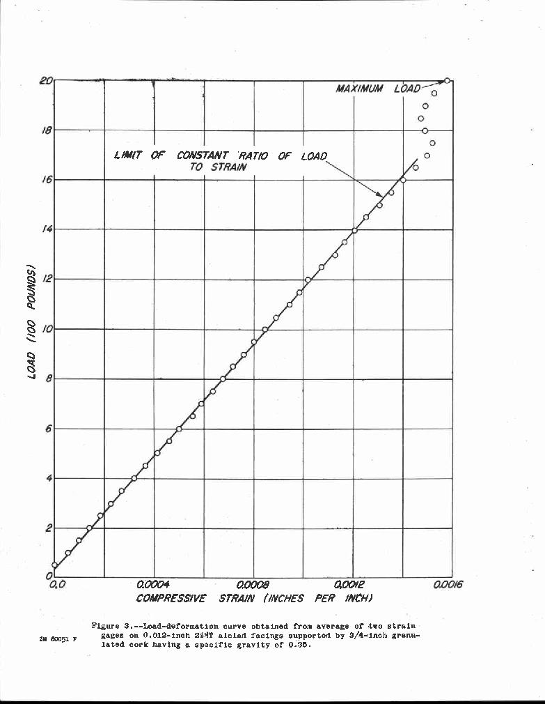
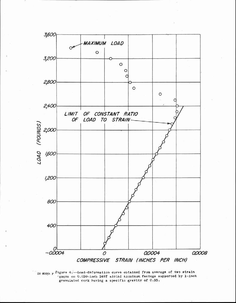
4 Specimens cut from 27 sandwich panels having four different thicknesses of 24ST alclad aluminum facings in combination with three different thicknesses of each of the two grades of cork boards were tested in shear. The thicknesses of the panels and of their cores and facings are listed in the first three columns of tables 1 and 2. Two sizes of shear panels were tested. The central parts of the shear specimens having inch facings on 1/2-inch cores were 2 inches square, and the others were 4 inches square. For the 2-inch specimens the load was applied in compression, as shown in figure 1, except that metalectric strain gages were used in place of the gages shown. For the 4-inch specimens the load was applied in tension, as shown in figure 2. Strains were measured in the compressive direction in both cases. Typical load-deformation curves are shown in figures 3 and 4. Coupons cut from the panels from which the shear specimens were taken were tested in the edgewise plane for the compressive stress at which instability of the facings occurred. The maximum compressive stresses were obtained according to the method referred to in Forest Products Laboratory deport No (revised October 1948) on coupons either 1-1/2 inches wide and about three times their thickness in height, or 2 inches wide and about four times their thickness in height. The values of the maximum compressive stress in the facings obtained from these tests are given in tables 1 and 2. Those values footnoted are each an average obtained from 10 coupons, 2 inches wide, five of which were tested with plaster disks at their bearing ends and five without. Agreement of individual values in these two groups of five coupons was very good, and it indicated no effect due to end restraint; therefore, the number of coupons was reduced to two. They were tested without end restraint, and the values obtained are not footnoted in tables 1 and 2. The results of the shear tests and the compression tests, both in the edgewise direction, are given in tables 1 and 2. The maximum shear stress of the respective sandwich constructions (col. 4) was compute- Id by: Pm PB = sh Where ps = shear stress of sandwich, in pounds per square inch (1) P m = maximum load on sandwich, in pounds s = length of the aide of the square portion of the specimen, in inches h = total thickness of panel, in inches The maximum shear stress of the facings of the respective sandwich constructions (col. 5) was computed by: Rept. No

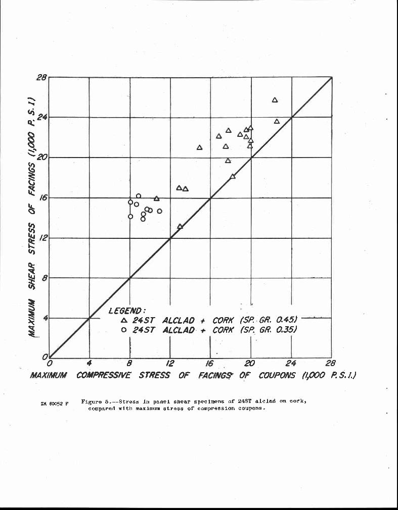
5 0.707 Pm Psf E, s(2f c) E f (2) where psf = shear stress of facings, in pounds per square inch f = thickness of a single facing, in inches E0 = modulus of elasticity of core, in pounds per square inch E f = modulus of elasticity of facing, in pounds per square inch c = thickness of core, in inches The shear stress in the facings at the limit of proportionality of the load to the'strain (col. 6) was computed according to equation (2),' using the appropriate load rather than the maximum load. The maximum compressive stress of the facings of the coupons (col. 7) was computed by: Pf - P me E w(2f + za c) f (3) where p f = average compressive stress in facing, in pounds per square inch Pmc = maximum load on compression coupon, in pounds w = width of specimen, in inches Discussion of Results In figure 5 the maximum shear stresses obtained from the tests are plotted against the maximum compressive stresses obtained from tests of the coupons associated with the individual shear specimens. The maximum shear stress is, for each specimen, numerically equal to the maximum compressive component of the shear stress. It will be noted that the critical shear stress is usually greater than the critical compressive stress, on the average about 25 percent greater. During the tests it was noted the surface irregularities appeared on the shear specimens shortly before failure and that such irregularities were Rept. No


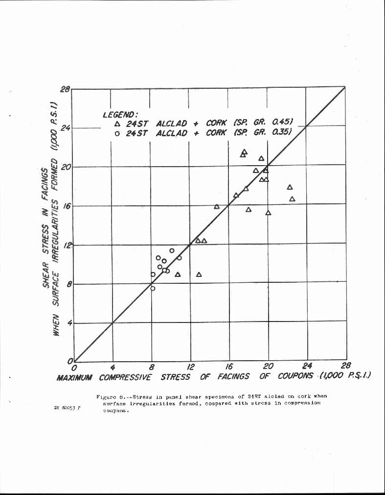
6 not visible on the compression specimens until failure occurred. It is probable that the tensile stresses associated with the compressive stresses in the shear specimens delayed actual failure. The formation of these irregularities is also evident on the load-strain curves taken during test. The strains were measured by means of metalectric strain gages, which record the sum of the bending and compressive strains of the facings. Samples of such curves are shown in figures 3 and 4. It will be noted that the strains are proportional to the loads until the irregularities form. Figure 6 is a plot of the stresses at which these irregularities form against the maximum stresses obtained from the coupons associated with the individual shear specimens. It will be noted that, on the average, the two stresses agree reasonably well. Figures 7 and 8 show samples of the failure of the shear panels. The samples were cut from the center of the panels parallel to the direction of compressive stresses. The wrinkles or amount of lateral displacement are a little exaggerated due to additional movement of the loading head of the testing machine after the maximum load had been obtained. The permanent set as shown indicates stresses above proportional limit of the material of the facings, but at the maximum load the calculated average stresses were below the proportional limit. Failures similar to these existed on the facings of the coupons tested in compression. It can be concluded that, for sandwich panels subjected to edgewise shear stress, the facings will become unstable due to the compressive component of the shear stress; but that failure will not occur at the exact value of the critical compressive stress due to the restraining effect of the associated tensile stress. It is believed that this conclusion can be extended to all cases of combined edgewise stress; that is, a fairly accurate estimate of the critical stress of the facings can be obtained by considering the maximum compressive component of the combined stress to be acting alone. Rept. No


7 Table l.--results of panel shear tests and compressive tests of sandwich constructions having 24ST alclad aluminum facings and granulated cork cores with specific gravity of 0.35 :. Thickness : Maximum shear : Limit of constant :Maximum compressive. stress : ratio of load to : stress in facings : : strain in facings : of coupons Facing: Core : Total :Sandwich:Facings: (1) : (2) : (3) : (4) : (5) : (6) (7) In. : In. : In. : P.s.i. : P.s.i.: P.s.i. P.s.i : : : 435 : 14,000: 10,320 9, :.775 : 457 : 14,750: 11,250 10,040 :.748 :.772 : 447 : 14,360: 9,300 9, :.773 : 455 : 14,670: 9,590 10,900,, : : 14,920: 9,300 9,760 :.973 : : 614 : 15,550: 8,840. 8, : : 628 : 16,150: 9,730. 8,830 =.986 : : 596 : 15,400: 10,610 8,730 :.980 : 1.020: 553 : 14,100: 7,520. 8,130.. Average of 10 coupons 2 inches wide, five tested with plaster disks at their bearing ends and five without. Rept. No. 1802


8 Table 2.--Results of panel shear tests and compressive tests of sandwich constructions having 24ST alclad aluminum facings and granulated cork cores with specific gravity of 0.45 Thickness : Maximum shear : Limit of constant :Maximum compressive. stress : ratio of load to : stress in facings : strain in facings : of coupons Facing: Core : Total :Sandwich: Facings:. 4 : : : :.: (1) : (2) : (3) : (4) : (5) : (6) : (7) In. : In. : In. : P.s.i. : P.s.i. : P.s.i.. P.s.i.... :. : : : : 13,110 : 8,85o 12,870 :.5o8 :.524 : 486 : 15,920 : 8,840 10,650.5o5 :.521 : 516 : 16,80o : 12,360 13, :.520 : 521 : 16,940 : 12,380 12,86o : : : 2 : 18,090 : 15,500 : 28,110,, : :.77b : bo9 : 19,050 : 17,740 17,760.., 1 : : 1.027: 000 : 25,700 : 17,700 22,320 : : : 494 : 21,100 : 21,100 17,470 : : : 529 : 22,690 : 21,400 : 17,770 : : : 517 : 22,100 : 17,000 : 16,820 : : : 514 : 22,000 : 20,680 : 19; : : 1,056 : 21,000 : 15,950 : 14,900 :. 1 : : 1.043, ' : fl 030 : : 15,050 : 120,080 : : : 870 : 22,720 : 18,540 : 19,550 : : : 803 : 21,000 : 19,440 : 19, : : 878 : 22,900 : 18,580 : 19,960 : : : 856 : 22,30o : 19,450 : 18,830..,.. : : : : 1,420 : 23,600 : 16,570 : 22,5oo Average of 10 coupons"2 inches wide, five tested with plaster disks at their bearing ends and five without. Rept. No. 1802

9 Figure l.--shear test showing method of loading ' used for the 2-inch specimens. Metalectric strain gages used in place of device shown. Z ) F

10 ZM F Figure 2.--Shear test showing method of loading used for the 4-inch specimens and method of obtaining measurement of deformations by means of a metalectric gage.
11
12
13

14

15 Figure 7.--Photographs of shear failures of sandwich constructions having aluminum facings and 0.45 specific gravity cork cores. A, inch 24ST alclad plus 1/2-inch cork; B, inch 24ST alclad plus 1/2-inch cork; C, inch 24ST alclad plus 1-inch cork; D, inch 24ST alclad plus 3/4-inch cork; E, inch 24ST alclad plus 1-inch Cork; F, inch 24ST alclad plus 1-inch cork. Z ":#6

16 ZM F Figure 8.--Photographs of shear failures of sandwich constructions having aluminum facing and 0.35 specific gravity cork cores. A, inch 24ST alclad plus 3/4-inch cork; B, inch 24ST alclad plus 1-inch cork.
WRINI CLING Of THE FACINGS OF SANDWICH CONSTRUCTION %EJECTED TO EDGEWISE COMPRESSION Sandwich Constructions Having Honeycomb Cores
 WRINI CLING Of THE FACINGS OF SANDWICH CONSTRUCTION %EJECTED TO EDGEWISE COMPRESSION Sandwich Constructions Having Honeycomb Cores June 1953 This Report is One of a Series Issued in Cooperation with the
COMPRESSIVE EUCICLING CURVES MR SANDWICH PANELS WITH ISOTROPIC FACINGS AND ISOTROPIC OR ORTI1OTROIPIC CORES. No Revised January 1958
 SRICULTU RE ROOM I COMPRESSIVE EUCICLING CURVES MR SANDWICH PANELS WITH ISOTROPIC FACINGS AND ISOTROPIC OR ORTI1OTROIPIC CORES No 1854 Revised January 1958 This Report is One of a Series Issued in Cooperation
ri [11111 IlL DIRECTIONAL PROPERTIES Of GLASS-FABRIC-BASE PLASTIC LAMINATE PANELS Of SIZES THAT DO NOT IBUCICLE (P-Q1lAtVjr) No.
 No.") Supplement to DIRECTIONAL PROPERTIES Of GLASS-FABRIC-BASE PLASTIC LAMINATE PANELS Of SIZES THAT DO NOT IBUCICLE (P-Q1lAtVjr) No. 1803-13 November 1955 This Report is One of a Series issued hi Cooperation
Supplement to DIRECTIONAL PROPERTIES Of GLASS-FABRIC-BASE PLASTIC LAMINATE PANELS Of SIZES THAT DO NOT IBUCICLE (P-Q1lAtVjr) No. 1803-13 November 1955 This Report is One of a Series issued hi Cooperation
EDGEWISE COMPRESSIVE STREW -Ill Of PANELS AND FIATWISE FLEXURAL STREW -Hi Of STRIPS Of SANDWICH CONSTRUCTIONS
 EDGEWISE COMPRESSIVE STREW -Ill Of PANELS AND FIATWISE FLEXURAL STREW -Hi Of STRIPS Of SANDWICH CONSTRUCTIONS November 1951 INFORMATION REVIEWED AND REAFFIRMED 1958 LOAN COPY Please return to: Wood Engineering
MINIMUM WEIGHT STRUCTURAL SANDWICH
 U.S. DEPARTMENT OF AGRICULTURE FOREST SERVICE FOREST PRODUCTS LABORATORY MADISON, WIS. In Cooperation with the University of Wisconsin U.S.D.A. FOREST SERVICE RESEARCH NOTE Revised NOVEMBER 1970 MINIMUM
DEFLECTION OF BEAMS WlTH SPECIAL REFERENCE TO SHEAR DEFORMATIONS
 DEFLECTION OF BEAMS WlTH SPECIAL REFERENCE TO SHEAR DEFORMATIONS THE INFLUENCE OF THE FORM OF A WOODEN BEAM ON ITS STIFFNESS AND STRENGTH-I (REPRINT FROM NATIONAL ADVISORY COMMITTEE FOR AERONAUTICS REPORT
EFFECT OF ELLIPTIC OR CIRCULAR HOLES ON THE STRESS DISTRIBUTION IN PLATES
 EFFECT OF ELLIPTIC OR CIRCULAR HOLES ON THE STRESS DISTRIBUTION IN PLATES OF WOOD OR PLYWOOD CONSIDERED AS ORTHOTROPIC MATERIALS Information Revied and Reaffirmed March 1956 No. 1510 EFFECT OF ELLIPTIC
BUCKLING COEFFICIENTS FOR SIMPLY SUPPORTED, FLAT, RECTANGULAR SANDWICH PANELS UNDER BIAXIAL COMPRESSION
 U. S. FOREST SERVICE RESEARCH PAPER FPL 135 APRIL 1970 BUCKLING COEFFICIENTS FOR SIMPLY SUPPORTED, FLAT, RECTANGULAR SANDWICH PANELS UNDER BIAXIAL COMPRESSION FOREST PRODUCTS LABORATORY, FOREST SERVICE
FLEXURE OF STRUCTURAL SANDWICH CONSTRUCTION
 FLEXURE OF STRUCTURAL SANDWICH CONSTRUCTION December 1951 INFORMATION REVIEWED AND REAFFIRMED 1958 LOAN COPY Please return to: Wood Engineering Research Forest Products Laboratory Madison, Wisconsin 53705
RELATIONSHIP BETWEEN RADIAL COMPRESSIVE MODULUS OF ELASTICITY AND SHEAR MODULUS OF WOOD Jen Y. Liu Research Engineer
 RELATIONSHIP BETWEEN RADIAL COMPRESSIVE MODULUS OF ELASTICITY AND SHEAR MODULUS OF WOOD Jen Y. Liu Research Engineer and Robert J. Ross Supervisory Research Engineer USDA Forest Service Forest Products
STRENGTH AND STIFFNESS REDUCTION OF LARGE NOTCHED BEAMS
 STRENGTH AND STIFFNESS REDUCTION OF LARGE NOTCHED BEAMS By Joseph F. Murphy 1 ABSTRACT: Four large glulam beams with notches on the tension side were tested for strength and stiffness. Using either bending
1.103 CIVIL ENGINEERING MATERIALS LABORATORY (1-2-3) Dr. J.T. Germaine Spring 2004 LABORATORY ASSIGNMENT NUMBER 6
 Dr. J.T. Germaine Spring 2004 LABORATORY ASSIGNMENT NUMBER 6") 1.103 CIVIL ENGINEERING MATERIALS LABORATORY (1-2-3) Dr. J.T. Germaine MIT Spring 2004 LABORATORY ASSIGNMENT NUMBER 6 COMPRESSION TESTING AND ANISOTROPY OF WOOD Purpose: Reading: During this laboratory
1.103 CIVIL ENGINEERING MATERIALS LABORATORY (1-2-3) Dr. J.T. Germaine MIT Spring 2004 LABORATORY ASSIGNMENT NUMBER 6 COMPRESSION TESTING AND ANISOTROPY OF WOOD Purpose: Reading: During this laboratory
A STUDY OF THE STRENGTH OF SHORT AND INTERMEDIATE WOOD COLUMNS BY EXPERIMENTAL AND ANALYTICAL METHODS
 UNITED STATES DEPARTMENT OF AGRICULTURE. FOREST SERVICE. FOREST PRODUCTS LABORATORY. MADISON, WIS A STUDY OF THE STRENGTH OF SHORT AND INTERMEDIATE WOOD COLUMNS BY EXPERIMENTAL AND ANALYTICAL METHODS January
Exercise 2: Bending Beam Load Cell
 Transducer Fundamentals The Strain Gauge Exercise 2: Bending Beam Load Cell EXERCISE OBJECTIVE When you have completed this exercise, you will be able to explain and demonstrate the operation of a board,
Properties of Southern Pine in Relation to Strength Grading of Dimension Lumber
 U. S. FOREST SERVICE RESEARCH PAPER FPL-64 JULY U.S. DEPARTMENT OF AGRICULTURE FOREST SERVICE FOREST PRODUCTS LABORATORY MADISON, WISCONSIN Properties of Southern Pine in Relation to Strength Grading of
[5] Stress and Strain
![[5] Stress and Strain](/thumbs/95/123344550.jpg "[5] Stress and Strain") [5] Stress and Strain Page 1 of 34 [5] Stress and Strain [5.1] Internal Stress of Solids [5.2] Design of Simple Connections (will not be covered in class) [5.3] Deformation and Strain [5.4] Hooke s Law
[5] Stress and Strain Page 1 of 34 [5] Stress and Strain [5.1] Internal Stress of Solids [5.2] Design of Simple Connections (will not be covered in class) [5.3] Deformation and Strain [5.4] Hooke s Law
EFFECTIVE THICKNESS OF PAPER: APPRAISAL AND FURTHER DEVELOPMENT
 EFFECTIVE THICKNESS OF PAPER: APPRAISAL AND FURTHER DEVELOPMENT USDA FOREST SERVICE RESEARCH PAPER FPL 287 1977 U.S. DEPARTMENT OF AGRICULTURE FOREST SERVICE FOREST PRODUCTS LABORATORY MADISON, WIS. Abstract
PLASTIC FLOW THROUGHOUT VOLUME OF THIN ADHESIVE!BONDS. No March 1958 (.2. Will In' iriculture ROOM. Mum mina
 iriculture ROOM (.2 PLASTIC FLOW THROUGHOUT VOLUME OF THIN ADHESIVE!BONDS No. 2092 March 1958 11 Will In' Mum mina FOREST PRODUCTS LABORATORY MADISON 5, WISCONSIN UNITED STATES DEPARTMENT OF AGRICULTURE
STRESSED-SKIN PANEL DEFLECTIONS AND STRESSES USDA FOREST SERVICE RESEARCH PAPER
 STRESSED-SKIN PANEL DEFLECTIONS AND STRESSES USDA FOREST SERVICE RESEARCH PAPER FPL 251 1975 U. S. DEPARTMENT OF AGRICULTURE FOREST SERVICE FOREST PRODUCTS LABORATORY MADISON, WISCONSIN ABSTRACT This paper
Lab Exercise #5: Tension and Bending with Strain Gages
 Lab Exercise #5: Tension and Bending with Strain Gages Pre-lab assignment: Yes No Goals: 1. To evaluate tension and bending stress models and Hooke s Law. a. σ = Mc/I and σ = P/A 2. To determine material
Optimum Fiber Distribution in Singlewall Corrugated Fiberboard
 United States Department of Agriculture Forest Service Forest Products Laboratory Research Paper FPL 348 1979 Optimum Fiber Distribution in Singlewall Corrugated Fiberboard Abstract Determining optimum
NDE of wood-based composites with longitudinal stress waves
 NDE of wood-based composites with longitudinal stress waves Robert J. Ross Roy F. Pellerin Abstract The research presented in this paper reveals that stress wave nondestructive testing techniques can be
Chapter Two: Mechanical Properties of materials
 Chapter Two: Mechanical Properties of materials Time : 16 Hours An important consideration in the choice of a material is the way it behave when subjected to force. The mechanical properties of a material
CHAPTER II EXPERIMENTAL INVESTIGATION
 CHAPTER II EXPERIMENTAL INVESTIGATION 2.1 SCOPE OF TESTING The objective of this research is to determine the force distribution between the column web and stiffener when the column flanges are subjected
Task 1 - Material Testing of Bionax Pipe and Joints
 Task 1 - Material Testing of Bionax Pipe and Joints Submitted to: Jeff Phillips Western Regional Engineer IPEX Management, Inc. 20460 Duncan Way Langley, BC, Canada V3A 7A3 Ph: 604-534-8631 Fax: 604-534-7616
THEORETICAL DESIGN OF A NAILED OR BOLTED JOINT UNDER LATERAL LOAD 1. Summary
 THEORETICAL DESIGN OF A NAILED OR BOLTED JOINT UNDER LATERAL LOAD 1 BY EDWARD W. KUENZI, 2 Engineer Forest Products Laboratory,3 Forest Service U. S. Department of Agriculture Summary This report presents
Stress-Strain Behavior
 Stress-Strain Behavior 6.3 A specimen of aluminum having a rectangular cross section 10 mm 1.7 mm (0.4 in. 0.5 in.) is pulled in tension with 35,500 N (8000 lb f ) force, producing only elastic deformation.
Samantha Ramirez, MSE. Stress. The intensity of the internal force acting on a specific plane (area) passing through a point. F 2
 passing through a point. F 2") Samantha Ramirez, MSE Stress The intensity of the internal force acting on a specific plane (area) passing through a point. Δ ΔA Δ z Δ 1 2 ΔA Δ x Δ y ΔA is an infinitesimal size area with a uniform force
Samantha Ramirez, MSE Stress The intensity of the internal force acting on a specific plane (area) passing through a point. Δ ΔA Δ z Δ 1 2 ΔA Δ x Δ y ΔA is an infinitesimal size area with a uniform force
Experiment Five (5) Principal of Stress and Strain
 Principal of Stress and Strain") Experiment Five (5) Principal of Stress and Strain Introduction Objective: To determine principal stresses and strains in a beam made of aluminum and loaded as a cantilever, and compare them with theoretical
Experiment Five (5) Principal of Stress and Strain Introduction Objective: To determine principal stresses and strains in a beam made of aluminum and loaded as a cantilever, and compare them with theoretical
The science of elasticity
 The science of elasticity In 1676 Hooke realized that 1.Every kind of solid changes shape when a mechanical force acts on it. 2.It is this change of shape which enables the solid to supply the reaction
Study of Pile Interval of Landslide Restraint Piles by Centrifuge Test and FEM Analysis
 Disaster Mitigation of Debris Flows, Slope Failures and Landslides 113 Study of Pile Interval of Landslide Restraint Piles by Centrifuge Test and FEM Analysis Yasuo Ishii, 1) Hisashi Tanaka, 1) Kazunori
ENG1001 Engineering Design 1
 ENG1001 Engineering Design 1 Structure & Loads Determine forces that act on structures causing it to deform, bend, and stretch Forces push/pull on objects Structures are loaded by: > Dead loads permanent
Mechanics of Materials Primer
 Mechanics of Materials rimer Notation: A = area (net = with holes, bearing = in contact, etc...) b = total width of material at a horizontal section d = diameter of a hole D = symbol for diameter E = modulus
LATERAL STABILITY OF DEEP BEAMS WITH SHEAR-BEAM SUPPORT
 U. FOREST SERVICE RESEARCH PAPER FPL 43 OCTOBER U. S. DEPARTMENT OF AGRICULTURE FOREST SERVICE FOREST PRODUCTS LABORATORY MADISON, WIS. LATERAL STABILITY OF DEEP BEAMS WITH SHEAR-BEAM SUPPORT The FOREST
Full Scale Structural Durability Test Spectrum Reduction by Truncation Coupon Testing
 Full Scale Structural Durability Test Spectrum Reduction by Truncation Coupon Testing Ogewu C. Agbese F-16/F-22 IFG Service Life Analysis Lockheed Martin Aeronautics Fort Worth, TX, USA ogewu.c.agbese@lmco.com
INTRODUCTION TO STRAIN
 SIMPLE STRAIN INTRODUCTION TO STRAIN In general terms, Strain is a geometric quantity that measures the deformation of a body. There are two types of strain: normal strain: characterizes dimensional changes,
1114, HM II rimill himini. WRINKLING OF THE FACINGS Of ALUMINUM AND STAINLESS STEEL SANDWICH SUIIIECTED IC
 WRINKLING OF THE FACINGS Of ALUMINUM AND STAINLESS STEEL SANDWICH SUIIIECTED IC EDGEWISE COMPRESSION Vecember 1959 No 2171 LOAN COPY Please return to: Wood Engineering Research Forest Products Laboratory
SIZE EFFECTS IN THE COMPRESSIVE CRUSHING OF HONEYCOMBS
 43rd AIAA/ASME/ASCE/AHS/ASC Structures, Structural Dynamics, and Materials Con 22-25 April 2002, Denver, Colorado SIZE EFFECTS IN THE COMPRESSIVE CRUSHING OF HONEYCOMBS Erik C. Mellquistand Anthony M.
ME 354, MECHANICS OF MATERIALS LABORATORY COMPRESSION AND BUCKLING
 ME 354, MECHANICS OF MATERIALS LABATY COMPRESSION AND BUCKLING PURPOSE 01 January 2000 / mgj The purpose of this exercise is to study the effects of end conditions, column length, and material properties
March No In Cooperation with the University of Wisconsin
 March 1956 No. In Cooperation with the University of Wisconsin STRESSES IN WOOD MEMBERS SUBJECTED TO COMBINED COLUMN AND BEAM ACTION.* J. A. NEWLIN and G. W. TRAYER. INTRODUCTION. This publication is one
ME 243. Mechanics of Solids
 ME 243 Mechanics of Solids Lecture 2: Stress and Strain Ahmad Shahedi Shakil Lecturer, Dept. of Mechanical Engg, BUET E-mail: sshakil@me.buet.ac.bd, shakil6791@gmail.com Website: teacher.buet.ac.bd/sshakil
DIRECTIONAL!PROPERTIES OF GLASS-FABRIC-I3ASE!PLASTIC LAMINATE PANELS OF SIZES THAT DO NOT 13IJCICILE
 DIRECTIONAL!PROPERTIES OF GLASS-FABRIC-I3ASE!PLASTIC LAMINATE PANELS OF SIZES THAT DO NOT 13IJCICILE Information Reviewed and Reaffirmed March 1956 No. 1803 Please return to: Wood Engineering Research
NORMAL STRESS. The simplest form of stress is normal stress/direct stress, which is the stress perpendicular to the surface on which it acts.
 NORMAL STRESS The simplest form of stress is normal stress/direct stress, which is the stress perpendicular to the surface on which it acts. σ = force/area = P/A where σ = the normal stress P = the centric
Lecture 8 Viscoelasticity and Deformation
 Read: pg 130 168 (rest of Chpt. 4) 1 Poisson s Ratio, µ (pg. 115) Ratio of the strain in the direction perpendicular to the applied force to the strain in the direction of the applied force. For uniaxial
American Society for Testing and Materials (ASTM) Standards. Mechanical Testing of Composites and their Constituents
 Standards. Mechanical Testing of Composites and their Constituents") Mechanical Testing of Composites and their Constituents American Society for Testing and Materials (ASTM) Standards Tests done to determine intrinsic material properties such as modulus and strength for
Mechanical Testing of Composites and their Constituents American Society for Testing and Materials (ASTM) Standards Tests done to determine intrinsic material properties such as modulus and strength for
Stress Strain Elasticity Modulus Young s Modulus Shear Modulus Bulk Modulus. Case study
 Stress Strain Elasticity Modulus Young s Modulus Shear Modulus Bulk Modulus Case study 2 In field of Physics, it explains how an object deforms under an applied force Real rigid bodies are elastic we can
What is a Strain Gauge? Strain Gauge. Schematic View Of Strain Gauge
 ( ) : 1391-92 92 What is Strain? Strain is the amount of deformation of a body due to an applied force. More specifically, strain (ε) is defined as the fractional change in length. Strain can be positive
Statistical Fatigue Experiment Design in Medium Density Fiberboard
 Materials Research, Vol. 3, No. 3, 84-91, 2000. 2000 Statistical Fatigue Experiment Design in Medium Density Fiberboard Mariano Martínez Espinosa a, Carlito Calil Jr. b a Instituto de Física de São Carlos,
Tensile stress strain curves for different materials. Shows in figure below
 Tensile stress strain curves for different materials. Shows in figure below Furthermore, the modulus of elasticity of several materials effected by increasing temperature, as is shown in Figure Asst. Lecturer
Static Bending Moment Capacity of T-Type Gusset-Plate Joints in Oriented Strandboard
 ORAL PRESENTATION Static Bending Moment Capacity of T-Type Gusset-Plate Joints in Oriented Strandboard Samet Demirel 1, and Jilei Zhang 2 1 Res. Asst. Dr., Karadeniz Technical University, Trabzon Turkey;
Module 5: Failure Criteria of Rock and Rock masses. Contents Hydrostatic compression Deviatoric compression
 FAILURE CRITERIA OF ROCK AND ROCK MASSES Contents 5.1 Failure in rocks 5.1.1 Hydrostatic compression 5.1.2 Deviatoric compression 5.1.3 Effect of confining pressure 5.2 Failure modes in rocks 5.3 Complete
Date Submitted: 1/8/13 Section #4: T Instructor: Morgan DeLuca. Abstract
 Lab Report #2: Poisson s Ratio Name: Sarah Brown Date Submitted: 1/8/13 Section #4: T 10-12 Instructor: Morgan DeLuca Group Members: 1. Maura Chmielowiec 2. Travis Newberry 3. Thomas Cannon Title: Poisson
2.1 Background of Piping Stresses
 2 Research Review One of the major additions to Tmin was the inclusion of analysis of a 2-Dimensional vertical piping span. The original plan from Dupont was to include several types of 2-D and 3-D vertical
TINIUS OLSEN Testing Machine Co., Inc.
 Interpretation of Stress-Strain Curves and Mechanical Properties of Materials Tinius Olsen has prepared this general introduction to the interpretation of stress-strain curves for the benefit of those
Solid Mechanics Chapter 1: Tension, Compression and Shear
 Solid Mechanics Chapter 1: Tension, Compression and Shear Dr. Imran Latif Department of Civil and Environmental Engineering College of Engineering University of Nizwa (UoN) 1 Why do we study Mechanics
NAME: Given Formulae: Law of Cosines: Law of Sines:
 NME: Given Formulae: Law of Cosines: EXM 3 PST PROBLEMS (LESSONS 21 TO 28) 100 points Thursday, November 16, 2017, 7pm to 9:30, Room 200 You are allowed to use a calculator and drawing equipment, only.
TESTING AND ANALYSIS OF COMPOSITE SANDWICH BEAMS
 TESTING AND ANALYSIS OF COMPOSITE SANDWICH BEAMS I. M. Daniel, J. L. Abot, and K. A. Wang Walter P. Murphy Professor, Departments of Civil and Mechanical Engineering, Robert R. McCormick School of Engineering
Commentary on Factors Affecting Transverse Vibration Using an Idealized Theoretical Equation
 United States Department of Agriculture Forest Service Forest Products Laboratory Research Note FPL RN 076 Commentary on Factors Affecting Transverse Vibration Using an Idealized Theoretical Equation Joseph
SOUTH AFRICAN NATIONAL STANDARD. Modulus of elasticity and modulus of rupture in static bending of fibreboards Amdt 1
 ISBN 978-0-66-956-7 Any reference to SABS SM 1015 is deemed to be a reference to this standard (Government Notice No. 17 of 8 November 00) SOUTH AFRICAN NATIONAL STANDARD Modulus of elasticity and modulus
Project Engineer: Wesley Kinkler Project Number: 4.14 Submission Date: 11/15/2003. TAMUK Truss Company Trusses Made Simple
 Submission Date: 11/15/2003 TAMUK Truss Company Trusses Made Simple Table of Contents Introduction..3 Proposal.3 Solution..5 Hand Calculations 5 TRUSS2D 7 NENastran 7 Comparison of Results... 8 Data Analysis.10
Bending Load & Calibration Module
 Bending Load & Calibration Module Objectives After completing this module, students shall be able to: 1) Conduct laboratory work to validate beam bending stress equations. 2) Develop an understanding of
Mechanical Engineering Ph.D. Preliminary Qualifying Examination Solid Mechanics February 25, 2002
 student personal identification (ID) number on each sheet. Do not write your name on any sheet. #1. A homogeneous, isotropic, linear elastic bar has rectangular cross sectional area A, modulus of elasticity
Structural Metals Lab 1.2. Torsion Testing of Structural Metals. Standards ASTM E143: Shear Modulus at Room Temperature
 Torsion Testing of Structural Metals Standards ASTM E143: Shear Modulus at Room Temperature Purpose To determine the shear modulus of structural metals Equipment Tinius-Olsen Lo-Torq Torsion Machine (figure
GB/T / ISO 527-1:1993
 Translated English of Chinese Standard: GB/T1040.1-2006 www.chinesestandard.net Sales@ChineseStandard.net GB NATIONAL STANDARD OF THE PEOPLE S REPUBLIC OF CHINA ICS 83.080.01 G 31 GB/T 1040.1-2006 / ISO
(laod No \' V,R A " FI- 1 4, <4. ELASTIC STABILITY Of CYLINDRICAL SANDWICH SHELLS UNDER AXIAL AND LATERAL LOAD. July 1955
 ELASTIC STABILITY Of CYLIDRICAL SADWICH SHELLS UDER AXIAL AD LATERAL LOAD (laod o. 1852 July 1955 This Report is One of a Series Issued ha Cooperation with the AC-23 PAEL O SADWICH COSTRUCTIO of the Departments
Because the third wire carries practically no current (due to the voltmeter's extremely high internal resistance), its resistance will not drop any
, its resistance will not drop any") Strain gauges If a strip of conductive metal is stretched, it will become skinnier and longer, both changes resulting in an increase of electrical resistance end-to-end. Conversely, if a strip of conductive
Strain gauges If a strip of conductive metal is stretched, it will become skinnier and longer, both changes resulting in an increase of electrical resistance end-to-end. Conversely, if a strip of conductive
Project PAJ2 Dynamic Performance of Adhesively Bonded Joints. Report No. 3 August Proposed Draft for the Revision of ISO
 NPL Report CMMT(A)81 Project PAJ2 Dynamic Performance of Adhesively Bonded Joints Report No. 3 August 1997 Proposed Draft for the Revision of ISO 11003-2 Adhesives - Determination of Shear Behaviour of
COMPARISON BETWEEN TENSILE AND COMPRESSIVE YOUNG S MODULUS OF STRUCTURAL SIZE LUMBER
 COMPARISON BETWEEN TENSILE AND COMPRESSIVE YOUNG S MODULUS OF STRUCTURAL SIZE LUMBER Kwang-Mo Kin 1, Kug-Bo Shim 2 ABSTRACT: To evaluate MOE of glued laminated timber, usually non-destructive MOE values
STRESSES WITHIN CURVED LAMINATED BEAMS OF DOUGLAS-FIR
 UNITED STATES DEPARTMENT OF AGRICULTURE. FOREST SERVICE - FOREST PRODUCTS LABORATORY - MADISON, WIS. STRESSES WITHIN CURVED LAMINATED BEAMS OF DOUGLAS-FIR NOVEMBER 1963 FPL-020 STRESSES WITHIN CURVED LAMINATED
MECHANICS OF MATERIALS
 CHATR Stress MCHANICS OF MATRIALS and Strain Axial Loading Stress & Strain: Axial Loading Suitability of a structure or machine may depend on the deformations in the structure as well as the stresses induced
Steel Cross Sections. Structural Steel Design
 Steel Cross Sections Structural Steel Design PROPERTIES OF SECTIONS Perhaps the most important properties of a beam are the depth and shape of its cross section. There are many to choose from, and there
STANDARD SAMPLE. Reduced section " Diameter. Diameter. 2" Gauge length. Radius
 MATERIAL PROPERTIES TENSILE MEASUREMENT F l l 0 A 0 F STANDARD SAMPLE Reduced section 2 " 1 4 0.505" Diameter 3 4 " Diameter 2" Gauge length 3 8 " Radius TYPICAL APPARATUS Load cell Extensometer Specimen
ISO 178 INTERNATIONAL STANDARD. Plastics Determination of flexural properties. Plastiques Détermination des propriétés en flexion
 INTERNATIONAL STANDARD ISO 178 Fourth edition 2001-12-15 Plastics Determination of flexural properties Plastiques Détermination des propriétés en flexion Reference number ISO 2001 PDF disclaimer This PDF
STRUCTURAL ANALYSIS OF A WESTFALL 2800 MIXER, BETA = 0.8 GFS R1. By Kimbal A. Hall, PE. Submitted to: WESTFALL MANUFACTURING COMPANY
 STRUCTURAL ANALYSIS OF A WESTFALL 2800 MIXER, BETA = 0.8 GFS-411519-1R1 By Kimbal A. Hall, PE Submitted to: WESTFALL MANUFACTURING COMPANY OCTOBER 2011 ALDEN RESEARCH LABORATORY, INC. 30 Shrewsbury Street
Physical Properties Testing Technical Bulletin
 Technical Bulletin MANUFACTURER Raven Lining Systems 13105 E. 61 st Street, Suite A Broken Arrow, OK 74012 (918) 615-0020 TENSILE TESTING OF PLASTICS ASTM D638, ISO 527 Tensile tests measure the force
S HEAR S TRENGTH IN P RINCIPAL P LANE OF W OOD
 S HEAR S TRENGTH IN P RINCIPAL P LANE OF W OOD By Jen Y. Liu 1 and Lester H. Floeter 2 ABSTRACT: In this study, the writers used Tsai and Wu s tensor polynomial theory to rederive a formula originally
MECHANICS OF MATERIALS. Prepared by Engr. John Paul Timola
 MECHANICS OF MATERIALS Prepared by Engr. John Paul Timola Mechanics of materials branch of mechanics that studies the internal effects of stress and strain in a solid body. stress is associated with the
Crashworthiness of composite structures: Experiment and Simulation
 Crashworthiness of composite structures: Experiment and Simulation Francesco Deleo, Bonnie Wade and Prof. Paolo Feraboli (UW) Dr. Mostafa Rassaian (Boeing R&T) JAMS 2010 The Joint Advanced Materials and
Equilibrium. the linear momentum,, of the center of mass is constant
 Equilibrium is the state of an object where: Equilibrium the linear momentum,, of the center of mass is constant Feb. 19, 2018 the angular momentum,, about the its center of mass, or any other point, is
Size Effects In the Crushing of Honeycomb Structures
 45th AIAA/ASME/ASCE/AHS/ASC Structures, Structural Dynamics & Materials Conference 19-22 April 2004, Palm Springs, California AIAA 2004-1640 Size Effects In the Crushing of Honeycomb Structures Erik C.
Solid Mechanics Homework Answers
 Name: Date: Solid Mechanics Homework nswers Please show all of your work, including which equations you are using, and circle your final answer. Be sure to include the units in your answers. 1. The yield
Please review the following statement: I certify that I have not given unauthorized aid nor have I received aid in the completion of this exam.
 Group Number: Please review the following statement: I certify that I have not given unauthorized aid nor have I received aid in the completion of this exam. Signature: INSTRUCTIONS Begin each problem
Machine Direction Strength Theory of Corrugated Fiberboard
 Thomas J. Urbanik 1 Machine Direction Strength Theory of Corrugated Fiberboard REFERENCE: Urbanik.T.J., Machine Direction Strength Theory of Corrugated Fiberboard, Journal of Composites Technology & Research,
RESEARCH PROJECT NO. 26
 RESEARCH PROJECT NO. 26 DETERMINATION OF POISSON'S RATIO IN AD1 TESTING BY UNIVERSITY OF MICHIGAN REPORT PREPARED BY BELA V. KOVACS and JOHN R. KEOUGH \ MEMBER / / DUCTILE IRON \ SOCIETY Issued by the
TENSILE TESTS (ASTM D 638, ISO
 MODULE 4 The mechanical properties, among all the properties of plastic materials, are often the most important properties because virtually all service conditions and the majority of end-use applications
MAE 322 Machine Design. Dr. Hodge Jenkins Mercer University
 MAE 322 Machine Design Dr. Hodge Jenkins Mercer University What is this Machine Design course really about? What you will learn: How to design machine elements 1) Design so they won t break under varying
, N U No TORSIOI_AL S _TP_ENG_'w OF N!oKEL,4 STEEL AND DURALU}_iN TUBING. AS AFFECTED BY THE RATIO OF DIA}:_ETER TO CCaGE THICKNESS.
 ,,-, j - X, N U 52189 i i u, TECHNICAL NOTES NATIONAL _- o - ADv IoORY CO_,_{ITTEE FOR AERONAUTICS. cas COp.y LE: No. 189 TORSIOI_AL S _TP_ENG_'w OF N!oKEL,4 STEEL AND DURALU}_iN TUBING AS AFFECTED BY
Lecture 15 Strain and stress in beams
 Spring, 2019 ME 323 Mechanics of Materials Lecture 15 Strain and stress in beams Reading assignment: 6.1 6.2 News: Instructor: Prof. Marcial Gonzalez Last modified: 1/6/19 9:42:38 PM Beam theory (@ ME
5. What is the moment of inertia about the x - x axis of the rectangular beam shown?
 1 of 5 Continuing Education Course #274 What Every Engineer Should Know About Structures Part D - Bending Strength Of Materials NOTE: The following question was revised on 15 August 2018 1. The moment
Concrete Technology Prof. B. Bhattacharjee Department of Civil Engineering Indian Institute of Technology, Delhi
 Concrete Technology Prof. B. Bhattacharjee Department of Civil Engineering Indian Institute of Technology, Delhi Lecture - 25 Strength of Concrete: Factors Affecting Test Results Welcome to module 6, lecture
PDDC 1 st Semester Civil Engineering Department Assignments of Mechanics of Solids [ ] Introduction, Fundamentals of Statics
![PDDC 1 st Semester Civil Engineering Department Assignments of Mechanics of Solids [ ] Introduction, Fundamentals of Statics](/thumbs/92/109382806.jpg "PDDC 1 st Semester Civil Engineering Department Assignments of Mechanics of Solids [ ] Introduction, Fundamentals of Statics") Page1 PDDC 1 st Semester Civil Engineering Department Assignments of Mechanics of Solids [2910601] Introduction, Fundamentals of Statics 1. Differentiate between Scalar and Vector quantity. Write S.I.
Page1 PDDC 1 st Semester Civil Engineering Department Assignments of Mechanics of Solids [2910601] Introduction, Fundamentals of Statics 1. Differentiate between Scalar and Vector quantity. Write S.I.
MECE 3321 MECHANICS OF SOLIDS CHAPTER 3
 MECE 3321 MECHANICS OF SOLIDS CHAPTER 3 Samantha Ramirez TENSION AND COMPRESSION TESTS Tension and compression tests are used primarily to determine the relationship between σ avg and ε avg in any material.
High Tech High Top Hat Technicians. An Introduction to Solid Mechanics. Is that supposed to bend there?
 High Tech High Top Hat Technicians An Introduction to Solid Mechanics Or Is that supposed to bend there? Why don't we fall through the floor? The power of any Spring is in the same proportion with the
Mechanics of Materials
 Mechanics of Materials Notation: a = acceleration = area (net = with holes, bearing = in contact, etc...) SD = allowable stress design d = diameter of a hole = calculus symbol for differentiation e = change
Section Downloads. Design Process. Design Principles Outline. Basic Design Principles. Design Process. Section 06: Design Principles.
 Section Downloads Section 06: Design Principles 1 Download & Print TTT I Sec 06 Slides TTT I Sec 06 Handout Section 05 Truss Materials Design Values PS 20 Section 01 TPI 1-2007 Selection 6.4.2 Repetitive
CEEN 3320 Behavior & Properties of Engineering Materials Laboratory Experiment No. 1 Measurement Techniques
 Laboratory Experiment No. 1 Measurement Techniques Engineers rely on data from a wide variety of sources to design the things that make up our physical world and to ensure compliance with established specifications.
Tvestigated using the quadratic form of the Tsai-Wu strength theory [I].
![Tvestigated using the quadratic form of the Tsai-Wu strength theory [I].](/thumbs/87/97080058.jpg "Tvestigated using the quadratic form of the Tsai-Wu strength theory [I].") Evaluation of Strength the TensorPolynomial Theory for Wood J. Y. L IU* Forest Products Laboratory, Forest Service U.S. Department of Agriculture, Madison, Wisconsin 53705 (Received October 10, 1983) (Revised
Evaluation of Strength the TensorPolynomial Theory for Wood J. Y. L IU* Forest Products Laboratory, Forest Service U.S. Department of Agriculture, Madison, Wisconsin 53705 (Received October 10, 1983) (Revised
1131UCIAING CIF RAG, MN, PLYWOOD CYLINDERS IN AXIAL COMPRESSION
 1131UCIAING CIF RAG, MN, PLYWD CYLINDERS IN AXIAL CMPRESSIN I nieftnatiett IkavictuciLn4-114cattirmyd March 1 &6 INFRMAIMN REV AND REAFFIRML 1962 No. 1322 LAN CPY Please return to: Wood Engineering Research
The University of Texas at Austin
 r The University of Texas at Austin College of Engineering COEFFICIENT OF THERMAL EXPANSION FOR FOUR BATCH DESIGNS AND ONE SOLID GRANITE SPECIMEN by A Report Prepared for FOSTER YEOMAN LIMITED by the CENTER
Structures - Experiment 3B Sophomore Design - Fall 2006
 Structures - Experiment 3B 1.101 Sophomore Design - Fall 2006 Linear elastic behavior of a beam. The objectives of this experiment are to experimentally study the linear elastic behavior of beams under