Solution of Coupled Thermoelasticity Problem In Rotating Disks
|
|
|
- Nancy Jennings
- 5 years ago
- Views:
Transcription

1 Cotutelle Doctoral Program Doctoral Dissertation on Solution of Coupled Thermoelasticity Problem In Rotating Disks by Ayoob Entezari Supervisors: Prof. M. A. Kouchakzadeh¹ and Prof. Erasmo Carrera² Advisor: Dr. Matteo Filippi² ¹Sharif University of Technology Department of Aerospace Engineering, Tehran, Iran ²MUL2 research group, Polytechnic University of Turin, Italy 26 September, 2017 ²Polytechnic University of Turin, Department of Mechanical and Aerospace Engineering, Italy
2 Outlines 1. Introduction to rotating disks 2. Fundamentals of Linear Thermoelasticity 3. Literature review & present work 4. Analytical approach 5. Numerical approach 6. Conclusion
3 Outlines 1. Introduction to rotating disks 2. Fundamentals of Linear Thermoelasticity 3. Literature review & present work 4. Analytical approach 5. Numerical approach 6. Conclusion

 Mechanical (spindles, flywheel, brake")
 Naval Power plant (steam and gas turbines,")
4 Introduction to rotating disks Applications Aerospace (aero-engines, turbo-pumps, turbo-chargers, etc.) Mechanical (spindles, flywheel, brake disks, etc.) Naval Power plant (steam and gas turbines, turbo-generators, ) Chemical plant Electronics (electrical machines) 4

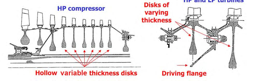
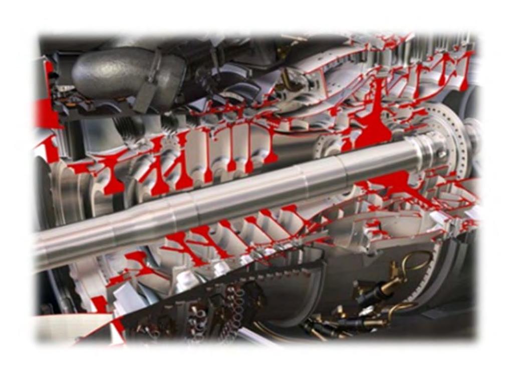
5 Introduction to rotating disks Configurations 5
6 Introduction to rotating disks Operating conditions Main Loads Centrifugal forces Thermal loads. start and stop cycles I) start up, II) shut down Transient thermal load In some of applications, the disks may be exposed to sudden temperature changes in short periods of time (for Ex. start and stop cycles) These sudden changes in temperature can cause time dependent thermal stresses. Thermal stresses due to large temperature gradients are higher than the steady-state stresses. In such conditions, the disk should be designed with consideration of transient effects. 6
+Pc ceramic-metal FGM Pm and Pc : properties of metal and ceramic Vm and Vc : volume fractions of metal and ceramic Vm")
7 Introduction to rotating disks Disk materials Metals: steels, super alloys Ceramic matrix composites (CMC) Functionally graded materials (FGMs) ceramic-metal FGM Effective properties of FGMs P eff = VmPm +Vc Pc =Vm (Pm Pc)+Pc ceramic-metal FGM Pm and Pc : properties of metal and ceramic Vm and Vc : volume fractions of metal and ceramic Vm =(,,) 7
+Pc 8")
8 Introduction to rotating disks FGM disk power gradation law for metal volume fraction along the radius Vm = metal volume fraction Effective properties of FGMs P eff = VmPm +Vc Pc =Vm (Pm Pc)+Pc 8 radius
9 Outlines 1. Introduction to rotating disk 2. Fundamentals of Linear Thermoelasticity 3. Literature review & present work 4. Analytical approach 5. Numerical approach 6. Conclusion
10 Fundamentals of Linear Thermoelasticity Classification of thermoelastic problems Inertia effects static problems dynamic problems displacement and temperature fields interaction uncoupled problems coupled problems 10
11 Fundamentals of Linear Thermoelasticity Classification of thermoelastic problems static steady-state problems equation of motion (, ), ( ), + =0 energy equation (, ), = temperature change displacements elastic coefficients body forces thermoelastic moduli thermal conductivity internal heat source 11

 = + ln( ( ) )")
12 Fundamentals of Linear Thermoelasticity Classification of thermoelastic problems static steady-state problems Under axisymmetric & plane stress assumptions equation of motion h h + h =0 energy equation () = + ln( ( ) ) 12
13 Fundamentals of Linear Thermoelasticity Classification of thermoelastic problems Quasi-static problems equation of motion (, ), ( ), + =0 energy equation,, = density specific heat 13
14 Fundamentals of Linear Thermoelasticity Classification of thermoelastic problems Dynamic uncoupled problems equation of motion (, ), ( ), + = energy equation,, = 14
15 Fundamentals of Linear Thermoelasticity Classification of thermoelastic problems Dynamic uncoupled problems Considering mechanical damping equation of motion (, ), ( ), + = + energy equation,, = mechanical damping coefficient of material 15
16 Fundamentals of Linear Thermoelasticity Classification of thermoelastic problems Coupled thermoelasticity the time rate of strain is taken into account in the energy equation elasticity and energy equations are coupled. these coupled equations must be solved simultaneously. equation of motion energy equation Mechanical and thermal BCs and ICs (,), (,) 16
17 Fundamentals of Linear Thermoelasticity Classification of thermoelastic problems Classical coupled problems equation of motion (, ), ( ), + =, energy equation, +, = reference temperature 17
18 Fundamentals of Linear Thermoelasticity Classification of thermoelastic problems Classical coupled problems equation of motion (, ), ( ), + =, energy equation, +, = reference temperature infinite propagation speed for the thermal disturbances!!! 18

19 Fundamentals of Linear Thermoelasticity Classification of thermoelastic problems in the classical thermoelasticity heat conduction equation is of a parabolic type. Predicting infinite speed for heat propagation The prediction is not physically acceptable. thermal wave disturbances are not detectable. generalized theories of thermoelasticity non-classical theories with the finite speed of the thermal wave. 19
, ( ), + = + (, ), +, +, =+ + 2, (, ), +, =,, +, = 20 LS relaxation time, GL relaxation times GL material constants GN material")
20 Fundamentals of Linear Thermoelasticity Classification of thermoelastic problems without energy dissipation (, ), ( ), + = (, ), ( ), ( ), + = (, ), ( ), + = + (, ), +, +, =+ + 2, (, ), +, =,, +, = 20 LS relaxation time, GL relaxation times GL material constants GN material constants
21 Outlines 1. Introduction to rotating disk 2. Fundamentals of Linear Thermoelasticity 3. Literature review & present work 4. Analytical approach 5. Numerical approach 6. Conclusion
22 Literature review & present work Conclusion of the literature review Coupled thermoelasticity problems are still topics of active research. Analytical solution of the these problems are mathematically difficult. Number of papers on analytical solutions is limited. Numerical methods are often used to solve these problems. Numerical solutions of these problems have been presented in many articles. Finite element method is still applied as a powerful numerical tool in such problems. The major presented solutions are related to the basic problems (infinite medium, half-space, layer and axisymmetric problems). Analytical and numerical solution of rotating disk problems has never before been presented. 22
23 Literature review & present work Present work Main purpose Study of coupled thermoelastic behavior in disks subjected to thermal shock loads based on the generalized and classic theories Disks with constant and variable thickness Made of FGM Implementation Analytical approach Numerical approach 23
24 Outlines 1. Introduction to rotating disk 2. Fundamentals of Linear Thermoelasticity 3. Literature review & present work 4. Analytical approach Solution method Numerical evaluation 5. Numerical approach 6. Conclusion 24
25 Analytical approach - Solution method Governing equations Consider An annular rotating disk with constant thickness, made of isotropic & homogeneous material, Under axisymmetric thermal and mechanical shock loads. Based on LS generalized coupled theory Eq. of motion (, ), ( ), + = =0 I energy Eq. + (, ), +, +, =+ ( +2) = II 25 = 2 +2 = & Lame constants coefficient of linear thermal expansion
26 Analytical approach - Solution method Governing equations Coupled System Of Equations I =0 II ( +2) = thermal BCs. & ICs Mechanical BCs. & ICs + (,)= () + (,)= () +, = + (,)= () - Inner radius of the disk Outer radius of the disk time dependent known functions 26, 0 =, (, 0) = (), 0 =, (, 0) = () constant parameters known functions of
27 Analytical approach - Solution method Governing equations in Non-dimensional form Non-dimensional parameters =, =, = =, = +2), =, = = propagation speed of elastic longitudinal wave = +2) unit length = 27
28 Analytical approach - Solution method Governing equations in Non-dimensional form Coupled System Of Equations I = II =0 where = ( +2 Thermoelastic damping or coupling parameter Non-dimensional propagation speed of thermal wave = 1 28 Non-dimensional propagation speed of elastic longitudinal wave =1
29 Analytical approach - Solution method Solution of non-dimensional equations Coupled System Of Equations I = II =0 Thermal and mechanical BCs. & ICs 29 + (, ) = ( ) + (, ) = ( ) + (,) = ( ) + (, ) = ( ) (,0)= ( ), (,0)= ( ) (,0)= ( ), (,0)= ( )
30 Analytical approach - Solution method Solution of non-dimensional equations =0 energy Eq. decomposition + 1 =0 + 1 =, + +, + + (, ) = () + (, ) = () (, 0) = 0, (, 0) = 0 + (, ) = 0 + (, ) = 0 (, 0) = (), (, 0) = () 30 principle of superposition (, ) = (, ) + (, )
31 Analytical approach - Solution method Solution of non-dimensional equations decomposition = Eq. of motion + 1 =0 + (, ) = () + (, ) = () (, 0) = 0, (, 0) = =, + (, ) = 0 + (, ) = 0 (, 0) = (), (, 0) = () 31 principle of superposition (, ) = (, ) + (, )
32 Analytical approach - Solution method Solution of non-dimensional equations decomposition = Eq. of motion + 1 =0 + (, ) = () + (, ) = () (, 0) = 0, (, 0) = =, + (, ) = 0 + (, ) = 0 (, 0) = (), (, 0) = () 32 Bessel equation and can be separately solved using finite Hankel transform
33 Analytical approach - Solution method Solution of non-dimensional equations Finite Hankel transform kernel functions (, )= ( ) ( ) (, )= ( ) ( ) H[ (,)]= (, )= (, ) and are positive roots of the following equations (, ) H[ (, )] = (, )= (, ) (, ) + ( ( ) ( ) + ( ( ) ( ) + ( + ( 33 ( ) ( ) + ( =0 ( ) + ( ( ) + ( ( ) + ( ( ) ( ) + ( + ( ( ) + ( + ( = 0
34 Analytical approach - Solution method Solution of non-dimensional equations Uncoupled sub-ibvps (Bessel equations) 2 u1 1 u1 u u = r r r r 0 2 T1 1 T1 + - T t0t 1 = r r r 0 u k + k u ( a, t) = f ( t) r r = a u k + k u (, b t) = f () t r r = b u ( r, 0) = 0, u ( r, 0) = T k + k T ( a, t) = f ( t) r r = a T k + k T ( b, t) = f ( t) r r = b T ( r, 0) = 0, T ( r, 0) = Taking the finite Hankel transform 2 æ d ö u u f () t f () t ç ø hn 1 = 4-3 p è d3 Solving ODEs 2 æ d ö tt T T f() t f() t ç ø xm 1= 2-1 p è d1 34 u1 (, t hn ) T1 (, t x ) m
35 Analytical approach - Solution method Solution of non-dimensional equations Uncoupled sub-ibvps (Bessel equations) 2 æ d ö u u f () t f () t ç ø hn 1 = 4-3 p è d3 Solving ODEs 2 æ d ö tt T T f() t f() t ç ø xm 1= 2-1 p è d1 u1 (, t hn ) T1 (, t x ) m Inverse finite Hankel transforms (, ) = (, ) (, (, ) = (, ) (, ) 35 = 1 (, ), = 1 (, )
36 Analytical approach - Solution method Solution of non-dimensional equations decomposition = Eq. of motion + 1 =0 + (, ) = () + (, ) = () (, 0) = 0, (, 0) = =, + (, ) = 0 + (, ) = 0 (, 0) = (), (, 0) = () 36 (, ) = () (, ), (, ) = () (, )
37 Analytical approach - Solution method Solution of non-dimensional equations Coupled System Of Equations I = II =0 37 (, ) = (, ) (, ) + () (, ) (, ) = (, ) (, + () (, )
38 Outlines 1. Introduction to rotating disk 2. Fundamentals of Linear Thermoelasticity 3. Literature review & present work 4. Analytical approach Solution method Numerical evaluation 5. Numerical approach 6. Conclusion
39 Analytical approach - Numerical evaluation Specifications of numerical example geometry Boundary conditions =1 =2 material properties =40.4 GPa =27 GPa =23 10 K = 2707 kg/m 3 = 204 W/m K = 903 J/kg K at = = () =0 at = =0 =0 () =
40 Analytical approach - Numerical evaluation Validation Based on classical theory of coupled thermoelasticity Temperature Radial displacement Nondimensional Temperature (T) C =0.02, =0, r =1.5 Numerical Solution (Bagri & Eslami, 2004) Exact Solution Nondimensional Radial Displacement (u) C =0.02, =0, r =1.5 Exact Solution NumericalSolution(Bagri&Eslami,2004) mid-radius Nondimensional Time (t) Nondimensional Time (t) 40 Time history of the non-dimensional solution at mid-radius
41 Analytical approach - Numerical evaluation Validation Based on LS generalized theory of coupled thermoelasticity Temperature Radial displacement Nondimensional Temperature (T) t 0 =0.64, C =0.02, =0, r =1.5 Exact Solution Numerical (Bagri & Eslami, 2004) Nondimensional Radial Displacement (u) t 0 =0.64, C =0.02, =0, r =1.5 Exact Solution Numerical(Bagri&Eslami,2004) mid-radius Nondimensional Time (t) -0.2 Nondimensional Time (t) 41 Time history of the non-dimensional solution at mid-radius
42 Analytical approach - Numerical evaluation Results and discussion Based on LS generalized theory of coupled thermoelasticity temperature change radial displacement radial stress circumferential stress Nondimensional Temperature (T) t= T 0 =293 K, t 0 =0.64, =0.01 steady state Nondimensional Radius(r) Nondimensional Radial Displacement (u) T 0 =293 K, t 0 =0.64, = steady state t = Nondimensional Radius (r) t = Nondimensional Radial Stress ( rr ) steady state t =0.25 t =0.5 t =0.75 t =1 t =1.25 Nondimensional Radius (r) T 0 =293 K, t 0 =0.64, =0.01 Nondimensional Tangential Stress ( ) T 0 =293 K, t 0 =0.64, = steady state -0.4 t =0.25 t = t =0.75 t =1-0.6 t = Nondimensional Radius (r) radius radius radius radius Radial distribution for different values of the time. 42
43 Outlines 1. Introduction to rotating disk 2. Fundamentals of Linear Thermoelasticity 3. Literature review & present work 4. Analytical approach 5. Numerical approach 6. Conclusion
44 Outlines 1. Introduction to rotating disk 2. Fundamentals of Linear Thermoelasticity 3. Literature review & present work 4. Analytical approach 5. Numerical approach Motivation Development of method Evaluations and results 6. Conclusion
45 Numerical approach Motivations Analytical solutions are limited to those of a disk with simple geometry and boundary conditions. FE method is more widely used for this class of problems. 1D and 2D FE models are not able to provide all the desired information. 3D FE modeling techniques may be required for a detailed coupled thermoelastic analysis. 3D FE models still impose large computational costs, specially, in a time-consuming transient solution. There is a growing interest in the development of refined FE models with lower computational efforts. A refined FE approach was developed by Prof. Carrera et al. They formulated the FE methods on the basis of a class of theories of structures. 45


46 Numerical approach Main characteristics of FE models refined by Carrera 3D capabilities lower computational costs ability to analyze multi-field problems and multi-layered structures MUL2 research group, Polytechnic University, Turin, Italy 46
47 Outlines 1. Introduction to rotating disk 2. Fundamentals of Linear Thermoelasticity 3. Literature review & present work 4. Analytical approach 5. Numerical approach Motivation Development of method Evaluations and results 6. Conclusion
48 Numerical approach - Development of method Approaches to FE modeling Variational approach Weighted residual methods Weighted residual method based on Galerkin technique Efficient, high rate of convergence most common method to obtain a weak formulation of the problem 48
49 Numerical approach - Development of method Governing equations For anisotropic and nonhomogeneous materials. Including LS, GL and classical theories of thermoelasticity. Considering mechanical damping effect. Equation of motion Energy equation,,,,, Hooke s law ) = = = =0 classical theory = = =0 LS theory =0 GL theory. 49
= (,,) () (,,,)= (,,) () =1,, = number of nodal points in a")
50 Numerical approach - Development of method FE formulation through Galerkin technique In 3D conventional FE method (,,,)= (,,) () (,,,)= (,,) () =1,, = number of nodal points in a element 50
51 Numerical approach - Development of method FE formulation through Galerkin technique Weighting function (,,) Equation of motion energy equation, + = 0 ( + ) + 2,, +, +, = 0, 51
52 Numerical approach - Development of method FE formulation through Galerkin technique ( ) + ( ) + ( T σ) Eq. of motion = ( ) + ( ) ( β T ) + ) + ) energy Eq. + ( β T ) + ) (2 T ) + ( T κ ) = ( T ) + ( ) + ) 52
53 Numerical approach - Development of method Refined 1D FE model through Carrera unified formulation 3D beam-type structures 1D FE = () = () 53 =1,, = number of bar nodes
 = () = () (, ) = (, ) () (, ) = (, )Θ () 54 =1,, = number of bar nodes =1,, = number of terms of the expansion.")
54 Numerical approach - Development of method Refined 1D FE model through Carrera unified formulation 3D beam-type structures 1D FE Carrera unified formulation (CUF) = () = () (, ) = (, ) () (, ) = (, )Θ () 54 =1,, = number of bar nodes =1,, = number of terms of the expansion.
55 Numerical approach - Development of method Refined 1D FE model through CUF 1D FE CUF 1D FE-CUF = () = () (, ) = (, ) () (, ) = (, )Θ () (,,, ) = (,,) () (,,, ) = (,, ) Θ () weighting function in 1D FE-CUF (,, )= () (, ) 55 refined 1D 2-nodes element 3D 8-nodes element
 (, ) Θ () 1D FE modeling elements and shape functions in 1D FE modeling element B2 linear B2 quadratic 56 B4")
56 Numerical approach - Development of method Refined 1D FE model through CUF 1D FE-CUF (,,, ) = () (, ) () (,,, ) = () (, ) Θ () 1D FE modeling elements and shape functions in 1D FE modeling element B2 linear B2 quadratic 56 B4 cubic
57 Numerical approach - Development of method Refined 1D FE model through CUF 1D FE-CUF (,,, ) = () (, ) () (,,, ) = () (, ) Θ () In Carrera unified formulation selection of (, ) and (=1,, ) is arbitrary. various kinds of basic functions such as polynomials, harmonics and exponentials of any-order. For instance, different classes of polynomials such as Taylor, Legendre and Lagrange polynomials. 57
58 Numerical approach - Development of method Refined 1D FE model through CUF 1D FE-CUF (,,, ) = () (, ) () (,,, ) = () (, ) Θ () (, ) bi-dimensional Lagrange functions cross-sections can be discretized using Lagrange elements linear three-point (L3) quadratic six-point (L6) bilinear four-point (L4) biquadratic nine-point (L9) bi-cubic sixteen-point (L16) 58
59 Numerical approach - Development of method FE equations in CUF form Substituting 1D FE-CUF (,,, ) = () (, ) () (,,, ) = () (, ) Θ () weighting function (,, )= () (, ) into the weak forms of equation of motion and energy equation gives M d + G d + K d = p lmts ls lmts ls lmts ls mt, and 4 4 fundamental nuclei (FNs)of the mass, damping, and stiffness matrices 4 1 FN of the load vector δ 4 1 FN of the unknowns vector 59
60 Numerical approach - Development of method FE equations in CUF form 0 M d + G d + K d = p lmts ls lmts ls lmts ls mt + or + 0 = Different theories of thermoelasticity through the 1D FE-CUF structural damping effect Rayleigh damping model = + 60

61 Numerical approach - Development of method Assembly procedure via Fundamental Nuclei for each element M d + G d + K d = p lmts ls lmts ls lmts ls mt assembly procedure of FNs 3 B4 for whole structure MD + GD + KD = P total degrees of freedom DOF = 4 a model with 3 B4 / 2 L4, DOF=240 2 L4 61
62 Numerical approach - Development of method Time history analysis M d + G d + K d = p lmts ls lmts ls lmts ls mt Transfinite element technique taking Laplace lmts 2 lmts lmts ls mt [ M s + G s + K ] d = p K lmts eq * * the Laplace variable FN of the equivalent stiffness matrix denotes Laplace transform of the terms. Assembling & for whole structure K eq D * * = P solve 62 solution in Laplace domain Δ numerical inversion solution in time domain (Δ())
63 Numerical approach - Development of method Non-dimensional Equation for isotropic FGMs Non-dimensional parameters m ˆ i x = ; t = t ; i x l m ˆ m T u u t t m e m ˆ T ( l + 2 m ) V = ; ˆi = ; = T l T l d V l m m e ˆ i 0 0 mbm d m 1 1 ˆ 1 qˆ q t t n n i = i ; sˆ ij = sij ; i = i cmtdrmve bmtd Tdbm ˆ l ˆ D i = R = R T ( 2 ) m m i ; dbm cmtd lm + mm velocity of elastic longitudinal wave unit length diffusivity 63 V = ( l + 2 m )/ r e m m m m lm D m / Ve m = k / c r = m m m m D
64 Numerical approach - Development of method Non-dimensional FNs for isotropic FGMs based on LS theory 64 Transfinite element equation δ = or * * p ˆt F N ds ˆ F N dv ( e ) ( e ) = m t n * 1 = x t m + x t m ( e ) ( e ) S V * * m t n ˆ * 2 = ò ˆt y t m + ò y t m ( e ) ( e ) S V * * m t n ˆ * 3 = ò ˆt z t m + ò z t m ( e ) ( e ) S V * m t ˆ ˆ * * 4 = [( 0 + 1) ] t m + ( ˆi i ) t m V ò p F N ds F N dv p F N ds F N dv ò p t s R F N dv q n F N ds ò ò S K = s Cˆ F F I + Cˆ F F I tslm 2 ml ml 11 r t s L 22 t, x s, x L + Cˆ F F I + Cˆ F F I m, yl, y ml 66 t s L 44 t, z s, z L K Cˆ F F I Cˆ F F I tslm m, yl ml, = t sx, L 23 t, x s L K = Cˆ F F I + Cˆ F F I tslm ml ml t, z s, x L 21 t, x s, z L K =-Cˆ F F I K tslm ml 14 b t, x s L tslm 41 = C s tˆ + s Cˆ F F I tslm ( ) 0 b t sx, K = C( s tˆ + s) Cˆ F F I K = C( s tˆ + s) Cˆ F F I tslm b t sz, tslm ml, L ( ˆ ) ˆ ˆ ml K = s t + s C C F F I + + Cˆ F F I + Cˆ F F I ml m, yl, k t, x s, x L k t s L + Cˆ F F I k r ml t, z s, z L b t s c t s L ml L y ml L y y
65 Numerical approach - Development of method Non-dimensional FNs for isotropic FGMs based on LS theory = ò =ò A ( ) da ( e ) ( ) ml m, yl ml, y m, yl, y L L L L L m l m l m l m l I I I I N N N N N N N N dy ( e), y, y, y, y ˆ r ˆ b,, ˆ k C = C = C =, Cˆ c = r b k rm bm km cm c K = s Cˆ F F I + Cˆ F F I tslm 2 ml ml 11 r t s L 22 t, x s, x L + Cˆ F F I + Cˆ F F I m, yl, y ml 66 t s L 44 t, z s, z L K Cˆ F F I Cˆ F F I tslm m, yl ml, = t sx, L 23 t, x s L K = Cˆ F F I + Cˆ F F I tslm ml ml t, z s, x L 21 t, x s, z L K =-Cˆ F F I tslm ml 14 b t, x s L y 65 ( 2m+ l) Cˆ 11 = Cˆ 22 = Cˆ 33 = ( lm + 2 mm) ˆ ˆ ˆ m C44 = C55 = C66 = ( lm + 2 mm) Cˆ ˆ ˆ l 12 = C13 = C23 = ( l + 2 m ) thermoelastic coupling parameter C = m m c T 2 0bm r ( l + m ) m m m m K tslm 41 = C s tˆ + Cˆ F F I tslm tslm b t sz, tslm ( s ) 0 b t sx, K = C ( s tˆ + s) Cˆ F F I K = C ( s tˆ + s) Cˆ F F I ml, L ( ˆ ) ˆ ˆ ml K = s t + s C C F F I + + Cˆ F F I + Cˆ F F I ml m, yl, k t, x s, x L k t s L + Cˆ F F I k r ml t, z s, z L b t s c t s L ml L y ml L y
66 Outlines 1. Introduction to rotating disk 2. Fundamentals of Linear Thermoelasticity 3. Literature review & present work 4. Analytical approach 5. Numerical approach Motivation Development of method Evaluations and results 6. Conclusion
67 Outlines 1. Introduction to rotating disk 2. Fundamentals of Linear Thermoelasticity 3. Literature review & present work 4. Analytical approach 5. Numerical approach Motivation Development of method Evaluations and results 6. Conclusion o Static structural analysis Example 1. Rotating variable thickness disk Example 2. Rotating variable thickness disk subjected thermal load Example 3. Complex rotor o Static structural-thermal analysis Example 4. simple beam o Quasi-static structural-thermal analysis Example 5. simple beam o Dynamic coupled structural-thermal analysis Example 6. Constant thickness disk made of isotropic homogeneous materials Example 7. Constant thickness disk made of isotropic FGMs Example 8. variable thickness disk made of isotropic FGMs
68 Outlines 1. Introduction to rotating disk 2. Fundamentals of Linear Thermoelasticity 3. Literature review & present work 4. Analytical approach 5. Numerical approach Motivation Development of method Evaluations and results 6. Conclusion o Static structural analysis Example 1. Rotating variable thickness disk Example 2. Rotating variable thickness disk subjected thermal load Example 3. Complex rotor o Static structural-thermal analysis Example 4. simple beam o Quasi-static structural-thermal analysis Example 5. simple beam o Dynamic coupled structural-thermal analysis Example 6. Constant thickness disk made of isotropic homogeneous materials Example 7. Constant thickness disk made of isotropic FGMs Example 8. variable thickness disk made of isotropic FGMs
69 Numerical approach - Evaluations and results Static structural analysis Example 1. Rotating variable thickness disk Material properties Young s modulus 207 GPa Poisson s ratio 0.28 density () 7860 kg/m annular disk with hyperbolic profile =0.05 m h =0.06 m =0.2 m h =0.03 m = 2000 rad/s hub is assumed to be fully fixed h =
 8")
 32 L4 8352 (6) 16 B2, 7 CS (1/2/3/4/5/6/8) 32 L4 9504 (7) 18 B2, 8 CS (1/2/3/4/5/6/7/8) 32 L4 11040 (8) 22 B2, 8 CS (1/2/3/4/5/6/7/8) 32 L4 14496 *")
70 Numerical approach - Evaluations and results Static structural analysis Example 1. Rotating variable thickness disk 1D FE-CUF modeling Different 1D FE-CUF models of the disk Model Discretizing Along the axis Over the corss sections DOF (1) 8 B2, 3 CS * (2/6/8) 32 L (2) 8 B2, 4 CS (2/4/6/8) 32 L (3) 10 B2, 4 CS (2/4/6/8) 32 L (4) 12 B2, 5 CS (1/2/4/6/8) 32 L (5) 14 B2, 6 CS (1/2/3/4/6/8) 32 L (6) 16 B2, 7 CS (1/2/3/4/5/6/8) 32 L (7) 18 B2, 8 CS (1/2/3/4/5/6/7/8) 32 L (8) 22 B2, 8 CS (1/2/3/4/5/6/7/8) 32 L * 3 types of cross section (CS) with different radii 70 discretization along the axis
71 Numerical approach - Evaluations and results Static structural analysis Example 1. Rotating variable thickness disk verification of results Radial displacement 71 Model DOF Radial displacement (μm) At mid-radius At outer radius Analytical 1D CUF- FE (1) (1.10) (1.00) (2) (0.54) (0.36) (3) (0.54) (0.73) (4) (0.22) (0.27) (5) (0.41) (0.32) (6) (0.43) (0.23) (7) (1.47) (1.68) (8) (1.64) (1.63) 3D ANSYS (0.01) (0.30) ( ) : % difference with respect to the analytical solution. Radial Displacement, u r (m) Radius (m) Analytical Solution model (1): DOF=6240 model (2): DOF=5472 model (3): DOF=7200 model (4): DOF=7584 model (5): DOF=8352 model (6): DOF=9504 model (7): DOF=11040 model (8): DOF=14496 ANSYS: DOF=
72 Numerical approach - Evaluations and results Static structural analysis Example 1. Rotating variable thickness disk verification of results Radial displacement 72 Model DOF Radial displacement (μm) At mid-radius At outer radius Analytical 1D CUF- FE (1) (1.10) (1.00) (2) (0.54) (0.36) (3) (0.54) (0.73) (4) (0.22) (0.27) (5) (0.41) (0.32) (6) (0.43) (0.23) (7) (1.47) (1.68) (8) (1.64) (1.63) 3D ANSYS (0.01) (0.30) ( ) : % difference with respect to the analytical solution. Error < 0.6% Model (2) 2.6 times less DOFs of the 3D ANSYS model!!
 32 L4 3168 2 8 B2, (2/4/6/8) 32 L4 5472 3")
73 Numerical approach - Evaluations and results Static structural analysis Example 1. Rotating variable thickness disk 1D FE-CUF modeling Mesh refinement over the cross-sections model 1D FE-CUF Model DOF 1 8 B2, (1/2/3/4) 32 L B2, (2/4/6/8) 32 L B2, (5/7/9/14) 32 L B2, (4/8/12/16) 32 L B2, (10/12/14/20) 32 L
74 Numerical approach - Evaluations and results Static structural analysis Example 1. Rotating variable thickness disk verification of results Radial displacement 74 Radial Displacement, u r (m) effect of enriching the radial discretization Radius (m) Analytical Solution 8 B2, (1/2/3/4)32 L4, DOF= B2, (2/4/6/8)32 L4, DOF= B2, (5/7/9/14)32 L4, DOF= B2, (4/8/12/16)32 L4, DOF= B2, (10/12/14/20)32 L4, DOF=13536 ANSYS, DOF= Model DOF Radial displacement (μm) At mid-radius At outer radius Analytical 1D CUF FE B2, (1/2/3/4) 32 L (3.79) (2.27) 8 B2, (2/4/6/8) 32 L (0.54) (0.36) 8 B2, (5/7/9/14) 32 L (0.01) (0.36) 8 B2, (4/8/12/16) 32 L (0.01) (0.27) 8 B2, (10/12/14/20) 32 L (0.01) (0.36) 3D FE (ANSYS) (0.01) (0.30) ( ) Absolute percentage difference with respect to the analytical solution. Converged solution with 1.6 times less DOFs of the 3D ANSYS model!!
75 Outlines 1. Introduction to rotating disk 2. Fundamentals of Linear Thermoelasticity 3. Literature review & present work 4. Analytical approach 5. Numerical approach Motivation Development of method Evaluations and results 6. Conclusion o Static structural analysis Example 1. Rotating variable thickness disk Example 2. Rotating variable thickness disk subjected thermal load Example 3. Complex rotor o Static structural-thermal analysis Example 4. simple beam o Quasi-static structural-thermal analysis Example 5. simple beam o Dynamic coupled structural-thermal analysis Example 6. Constant thickness disk made of isotropic homogeneous materials Example 7. Constant thickness disk made of isotropic FGMs Example 8. variable thickness disk made of isotropic FGMs
76 Numerical approach - Evaluations and results Static structural analysis Example 2. Rotating variable thickness disk subjected thermal load The disk is subjected to radial temperature gradient. hub is assumed to be axially fixed. Temprature change (C) Radius (m) radial steady-state temperature distribution 76
77 Numerical approach - Evaluations and results Static structural analysis Example 2. Rotating variable thickness disk subjected thermal load radial displacement Radial and circumferential stresses u r (mm) rr (MPa) (MPa) Max=1.94 Min= Min= Max=238 Min=0.55 Max=541 radius radial stress circumferential stress radius 77
78 Outlines 1. Introduction to rotating disk 2. Fundamentals of Linear Thermoelasticity 3. Literature review & present work 4. Analytical approach 5. Numerical approach Motivation Development of method Evaluations and results 6. Conclusion o Static structural analysis Example 1. Rotating variable thickness disk Example 2. Rotating variable thickness disk subjected thermal load Example 3. Complex rotor o Static structural-thermal analysis Example 4. simple beam o Quasi-static structural-thermal analysis Example 5. simple beam o Dynamic coupled structural-thermal analysis Example 6. Constant thickness disk made of isotropic homogeneous materials Example 7. Constant thickness disk made of isotropic FGMs Example 8. variable thickness disk made of isotropic FGMs

79 Numerical approach - Evaluations and results Static structural analysis Example 3. Complex rotor The profile hyperbolic for the turbine disk web-type profile for the compressor disks Both ends of the shaft are fully fixed. 3D model of a complex rotor 79
80 Numerical approach - Evaluations and results Static structural analysis Example 3. Complex rotor 1D FE-CUF modeling discretizing along the axis B B2 40 B z (m) 0 z (m) 0 z (m) Beam Elements Beam Elements Beam Elements y (m) y (m) y (m) Lagrange mesh over the cross-section with the largest radius 80 uniform L4 refined L4
 0-0.1 32 Beam Elements -0.2 0 0.1 0.2 0.3 0.4 0.5 0.6 0.")
81 Numerical approach - Evaluations and results Static structural analysis Example 3. Complex rotor 1D FE-CUF modeling Converged model z (m) Beam Elements y (m) B2 along the axis refined L4 computational model, DOF=27072

 Turbine disk in the rotor (1D CUF result) Comp.")
82 Numerical approach - Evaluations and results Static structural analysis Example 3. Complex rotor verification of results Radial displacement 200 1D FE-CUF solution with 1.6 times less DOFs of the 3D ANSYS model!! u r (m) D FE-CUF solution DOFs= 27,072 3D FE ANSYS DOFs=44,280 Radial Displacement (m) x x x x x x x x x x x x x x x x x x x x x x x x x x x x x x x Turbine disk in the rotor (3D ANSYS result) Turbine disk in the rotor (1D CUF result) Comp. Disk 1 in the rotor Comp. Disk 2 in the rotor Radius (m)
83 Numerical approach - Evaluations and results Static structural analysis Example 3. Complex rotor verification of results Radial and circumferential stresses 550 rr (MPa) Radial stress rr Turbine disk in the rotor Single Turbine disk with rigid hub (MPa) Stress (MPa) rr Circumferential stress Radius (m)
84 Outlines 1. Introduction to rotating disk 2. Fundamentals of Linear Thermoelasticity 3. Literature review & present work 4. Analytical approach 5. Numerical approach Motivation Development of method Evaluations and results 6. Conclusion o Static structural analysis Example 1. Rotating variable thickness disk Example 2. Rotating variable thickness disk subjected thermal load Example 3. Complex rotor o Static structural-thermal analysis Example 4. simple beam o Quasi-static structural-thermal analysis Example 5. simple beam o Dynamic coupled structural-thermal analysis Example 6. Constant thickness disk made of isotropic homogeneous materials Example 7. Constant thickness disk made of isotropic FGMs Example 8. variable thickness disk made of isotropic FGMs

85 Numerical approach - Evaluations and results Static structural-thermal analysis Example 4. simple beam 1D FE-CUF modeling discretizing along the axis Lagrange elements over the cross-section 85

86 Numerical approach - Evaluations and results Static structural-thermal analysis Example 4. simple beam results Temperature change Axial displacement 86 1 L4 over the cross-section
87 Numerical approach - Evaluations and results Static structural-thermal analysis Example 4. simple beam results 1 L9 over the cross-section 87 1 L16 over the cross-section
88 Numerical approach - Evaluations and results Static structural-thermal analysis Example 4. simple beam verification of results Does heat conduction equation satisfy? Yes!! 88
89 Numerical approach - Evaluations and results Static structural-thermal analysis Example 4. simple beam verification of results Check free thermal expansion! Elongation = At =0.1 =(0.1 )( ).. = mm At =0.5 =(0.5 )( ). = mm 89
90 Outlines 1. Introduction to rotating disk 2. Fundamentals of Linear Thermoelasticity 3. Literature review & present work 4. Analytical approach 5. Numerical approach Motivation Development of method Evaluations and results 6. Conclusion o Static structural analysis Example 1. Rotating variable thickness disk Example 2. Rotating variable thickness disk subjected thermal load Example 3. Complex rotor o Static structural-thermal analysis Example 4. simple beam o Quasi-static structural-thermal analysis Example 5. simple beam o Dynamic coupled structural-thermal analysis Example 6. Constant thickness disk made of isotropic homogeneous materials Example 7. Constant thickness disk made of isotropic FGMs Example 8. variable thickness disk made of isotropic FGMs

91 Numerical approach - Evaluations and results Quasi-static structural-thermal analysis Example 5. simple beam Transient heat flux (thermal load) 91

92 Numerical approach - Evaluations and results Quasi-static structural-thermal analysis Example 5. simple beam results 10B4/1L4 model Axial displacement Temperature change Axial displacement Temperature change 92
93 Outlines 1. Introduction to rotating disk 2. Fundamentals of Linear Thermoelasticity 3. Literature review & present work 4. Analytical approach 5. Numerical approach Motivation Development of method Evaluations and results o Static structural analysis Example 1. Rotating variable thickness disk Example 2. Rotating variable thickness disk subjected thermal load Example 3. Complex rotor o Static structural-thermal analysis Example 4. simple beam o Quasi-static structural-thermal analysis Example 5. simple beam o Dynamic coupled structural-thermal analysis Example 6. Constant thickness disk made of isotropic homogeneous materials Example 7. Constant thickness disk made of isotropic FGMs Example 8. variable thickness disk made of isotropic FGMs Conclusion


 40.")
94 Numerical approach - Evaluations and results Dynamic coupled structural-thermal analysis Example 6. Constant thickness disk made of isotropic homogeneous materials Boundary conditions Material properties Lame constant λ Lame constant μ coefficient of linear thermal expansion (α) density (ρ) thermal conductivity (κ) specific heat (c) 40.4 GPa 27 GPa K 2707 kg/m 204 W/m K 903 J/kg K = = () =0 = =0 =0 where () = geometry =1 =2 Thickness =

95 Numerical approach - Evaluations and results Dynamic coupled structural-thermal analysis Example 6. Constant thickness disk made of isotropic homogeneous materials 1D FE-CUF modeling discretizing along the axis Different 1D FE-CUF models for the constant thickness disk Model Discretizing Along the axis corss sections DOF (1) 1 B (2) 1 B3 (6 30) L (3) 1 B (4) 3 15 L9 (5) 1 B L (6) 6 18 L Lagrange mesh over the cross-section with the largest radius 95
96 Numerical approach - Evaluations and results Dynamic coupled structural-thermal analysis Example 6. Constant thickness disk made of isotropic homogeneous materials verification of results Based on the LS theory of thermoelasticity 0.5 Temperature change 1 Radial displacement 0.45 t 0 =0.64, C =0.02, r = t 0 =0.64, C =0.02, r =1.5 Nondimensional Temperature (T) Exact Solution (Entezari, 2016) Axisymetric FE (Bagri, 2004) CUF: 1 B2/(618) L9 Nondimensional Radial Displacement (u) Exact Solution (Entezari, 2016) Axisymetric FE (Bagri, 2004) CUF: 1 B2/(618) L B2 / 6 18 L Nondimensional Time (t) -0.2 Nondimensional Time (t) 96 Time history of solution at mid-radius of the disk.

97 Numerical approach - Evaluations and results Dynamic coupled structural-thermal analysis Example 6. Constant thickness disk made of isotropic homogeneous materials verification of results Based on the LS theory of thermoelasticity 1 Radial stress 0.8 Circumferential stress Nondimensional Radial Stress ( rr ) t 0 =0.64, C =0.02, r = Exact Solution (Entezari, 2016) CUF: 1 B2/(618) L9 Nondimensional Tangential Stress ( ) t 0 =0.64, C =0.02, r =1.5 Exact Solution (Entezari, 2016) CUF: 1 B2/(618) L B2 / 6 18 L9-0.8 Nondimensional Time (t) -0.6 Nondimensional Time (t) 97 Time history of solution at mid-radius of the disk.
98 Outlines 1. Introduction to rotating disk 2. Fundamentals of Linear Thermoelasticity 3. Literature review & present work 4. Analytical approach 5. Numerical approach Motivation Development of method Evaluations and results 6. Conclusion o Static structural analysis Example 1. Rotating variable thickness disk Example 2. Rotating variable thickness disk subjected thermal load Example 3. Complex rotor o Static structural-thermal analysis Example 4. simple beam o Quasi-static structural-thermal analysis Example 5. simple beam o Dynamic coupled structural-thermal analysis Example 6. Constant thickness disk made of isotropic homogeneous materials Example 7. Constant thickness disk made of isotropic FGM Example 8. variable thickness disk made of isotropic FGMs


 2707 kg/m 3 3800 kg/m 3 coefficient of linear thermal expansion")
 903 J/kgK 760 J/kgK dimensionless relaxation time ( ) 0.")
99 Numerical approach - Evaluations and results Dynamic coupled structural-thermal analysis Example 7. Constant thickness disk made of isotropic FGM Geometry and material Material properties Metal-Ceramic FGM Metal: Aluminum Ceramic: Alumina Lame constant λ 40.4 GPa GPa shear modulus μ 27.0 GPa GPa density (ρ) 2707 kg/m kg/m 3 coefficient of linear thermal expansion (α) K K 1 thermal conductivity (κ) 204 W/mK 28.0 W/mK specific heat (c) 903 J/kgK 760 J/kgK dimensionless relaxation time ( ) effective properties P=VmPm +Vc Pc =Vm (Pm Pc)+Pc metal volume fraction Vm = geometry =1 =2 Thickness =
100 Numerical approach - Evaluations and results Dynamic coupled structural-thermal analysis Example 7. Constant thickness disk made of isotropic FGM Operational, boundary & initial conditions = 293 K, =0.01 at =0 = = ==0 Free T(t) () = (1 [ m m ] m Non-dimensional form ( ) = 1 ( ) m ) Adiabatic Fixed z x z y 100
 Based on the LS theory of")
101 Numerical approach - Evaluations and results Dynamic coupled structural-thermal analysis Example 7. Constant thickness disk made of isotropic FGM results Time history the material properties linearly change through the radius ( =1) Based on the LS theory of thermoelasticity Temperature change Radial displacement 101

 Based on the LS theory of thermoelasticity")
102 Numerical approach - Evaluations and results Dynamic coupled structural-thermal analysis Example 7. Constant thickness disk made of isotropic FGM results Time history the material properties linearly change through the radius ( =1) Based on the LS theory of thermoelasticity Deformations of disk profile Radial displacement radial deformation Axial deformation 102
103 Numerical approach - Evaluations and results Dynamic coupled structural-thermal analysis Example 7. Constant thickness disk made of isotropic FGM results Speed range of the thermal wave the material properties linearly change through the radius ( =1) Based on the LS theory of thermoelasticity 103
104 Numerical approach - Evaluations and results Dynamic coupled structural-thermal analysis Example 7. Constant thickness disk made of isotropic FGM results Speed range of the thermal wave the material properties linearly change through the radius ( =1) Based on the LS theory of thermoelasticity wave reflection 1/1.5=


105 Numerical approach - Evaluations and results Dynamic coupled structural-thermal analysis Example 7. Constant thickness disk made of isotropic FGM results Thermal wave propagation the material properties linearly change through the radius ( =1) Based on the LS theory of thermoelasticity Non-dimensional form of energy equation m,, mm =0, +, c = c m 1 c =0.27 wave reflection 1/1.5= m = 1 m =1.25 Speed range of the thermal wave 0.27,FGM
106 Numerical approach - Evaluations and results Dynamic coupled structural-thermal analysis Example 7. Constant thickness disk made of isotropic FGM results Elastic wave propagation the material properties linearly change through the radius ( =1) Based on the LS theory of thermoelasticity wave reflection 106
 Based on the LS theory of thermoelasticity")
107 Numerical approach - Evaluations and results Dynamic coupled structural-thermal analysis Example 7. Constant thickness disk made of isotropic FGM results Elastic wave propagation the material properties linearly change through the radius ( =1) Based on the LS theory of thermoelasticity Non-dimensional form of equation of motion wave reflection + m +2m +, + m +2m 1, + m +2m,, 1 m +2m,(, +, ) m 1 m, +, + =0 Speed range of elastic wave c =1.96 m =1 1 FGM
108 Numerical approach - Evaluations and results Dynamic coupled structural-thermal analysis Example 7. Constant thickness disk made of isotropic FGM results effects of power law index () Nondimensional temperature change (T) Temperature change Nondimensional time(t) at mid radius n =0 n =1 n =2 n =5 Nondimensional radial displacement (u r ) Radial displacement n =0 n =1 n =2 n = Nondimensional time(t) at mid radius metal volume fraction Vm = mid-radius Time history based on the LS theory at mid-radius of the disk 108
 Nondimensional radial stress ( rr ) 1.6 1.4 1.2 1 0.8 0.6 0.4 0.2 0-0.2-0.4-0.6-0.8-1 -1.2-1.4 Radial stress -1.")
109 Numerical approach - Evaluations and results Dynamic coupled structural-thermal analysis Example 7. Constant thickness disk made of isotropic FGM results effects of power law index () Nondimensional radial stress ( rr ) Radial stress Nondimensional time(t) n =0 n =1 n =2 n =5 at mid radius Circumferential stress Time history based on the LS theory at mid-radius of the disk Nondimensional circumferential stress ( ) Nondimensional time(t) n =0 n =1 n =2 n =5 at mid radius metal volume fraction Vm = mid-radius 109
110 Numerical approach - Evaluations and results Dynamic coupled structural-thermal analysis Example 7. Constant thickness disk made of isotropic FGM results effects of reference temperature ( ) Nondimensional temperature change (T) Temperature change Nondimensional time(t) at mid radius T 0 =0 T 0 =293 T 0 =800 Nondimensional radial displacement (u r ) Radial displacement Nondimensional time(t) at mid radius T 0 =0 T 0 =293 T 0 =800 coupling parameter = m mm(m +m) Time history based on the LS theory at mid-radius of the disk (n =1) mid-radius 110
 Nondimensional radial stress ( rr ) 1.6 1.4 1.2 1 0.8 0.6 0.4 0.2 0-0.2-0.4-0.6-0.")
111 Numerical approach - Evaluations and results Dynamic coupled structural-thermal analysis Example 7. Constant thickness disk made of isotropic FGM results effects of reference temperature ( ) Nondimensional radial stress ( rr ) Radial stress T 0 =0 T 0 = 293 T 0 = 800 at mid radius Nondimensional circumferential stress ( ) Circumferential stress T 0 =0 T 0 =293 T 0 =800 at mid radius coupling parameter = m mm(m +m) Nondimensional time(t) Nondimensional time(t) Time history based on the LS theory at mid-radius of the disk (n =1) mid-radius 111
112 Outlines 1. Introduction to rotating disk 2. Fundamentals of Linear Thermoelasticity 3. Literature review & present work 4. Analytical approach 5. Numerical approach Motivation Development of method Evaluations and results o Static structural analysis Example 1. Rotating variable thickness disk Example 2. Rotating variable thickness disk subjected thermal load Example 3. Complex rotor o Static structural-thermal analysis Example 4. simple beam o Quasi-static structural-thermal analysis Example 5. simple beam o Dynamic coupled structural-thermal analysis Example 6. Constant thickness disk made of isotropic homogeneous materials Example 7. Constant thickness disk made of isotropic FGM Example 8. variable thickness disk made of isotropic FGM Conclusion
113 Numerical approach - Evaluations and results Dynamic coupled structural-thermal analysis Example 8. variable thickness disk made of isotropic FGM Geometry and material 0.3 Material properties Metal-Ceramic FGM Metal: Aluminum Ceramic: Alumina Lame constant λ 40.4 GPa GPa shear modulus μ 27.0 GPa GPa density (ρ) 2707 kg/m kg/m 3 coefficient of linear thermal expansion (α) K K 1 thermal conductivity (κ) 204 W/mK 28.0 W/mK specific heat (c) 903 J/kgK 760 J/kgK dimensionless relaxation time ( ) h =0.42r -0.5 r 113 effective properties P=VmPm +Vc Pc =Vm (Pm Pc)+Pc metal volume fraction Vm = geometry ==0.5 = =2 h =0.6 h =0.3

 =")
114 Numerical approach - Evaluations and results Dynamic coupled structural-thermal analysis Example 8. variable thickness disk made of isotropic FGM = 293 K, =0.05 at =0 = = ==0 Operational, boundary & initial conditions () = (1 Non-dimensional form m) ( ) =1 114

115 Numerical approach - Evaluations and results Dynamic coupled structural-thermal analysis Example 8. variable thickness disk made of isotropic FGM Results for =0 1 Temperature change 1 Radial displacement Nondimensional temperature change Classic theory LS theory Nondimensional radial displacement Classic theory LS theory Nondimensional time Nondimensional time 115 Nondimensional radial stress Radial stress Nondimensional time Classic theory LS theory Nondimensional circumferential stress Circumferential stress Nondimensional time Classic theory LS theory Nondimensional von mises equivalent stress Von mises stress Classic theory LS theory Nondimensional time


116 Numerical approach - Evaluations and results Dynamic coupled structural-thermal analysis Example 8. variable thickness disk made of isotropic FGM Results for =0based LS theory 116

117 Numerical approach - Evaluations and results Dynamic coupled structural-thermal analysis Example 8. variable thickness disk made of isotropic FGM Results for =0based LS theory Axial displacement Radial displacement 117
118 Outlines 1. Introduction to rotating disks 2. Fundamentals of Linear Thermoelasticity 3. Literature review & present work 4. Analytical approach 5. Numerical approach 6. Conclusion 118
119 Conclusion - Summary of results Some results obtained from coupled thermoelasticity solution Transient deformations and stresses may be higher than those of a steady-state condition. Time history of temperature is damped faster than time history of displacements. Deformations and stresses oscillate alongthetimeinaharmonic form. Under the propagating longitudinal elastic waves along the radius, thickness of the disk also expands and contracts, due to the Poisson effect. When the coupling parameter takes a greater value, the amplitudes of oscillations of temperature increase. Lord Shulman generalized coupled thermoelasticity predicts larger temperature and stresses compared to the classical theories. 119 A functionally graded disk may be used as thermal barrier to reduce the thermal shock effects.
120 Conclusion - Summary of results Some general points on the 1D FE-CUF modeling of disks The 1D FE method refined by the CUF can be effectively employed to analyze disks reduce the computational cost of 3D FE analysis without affecting the accuracy. the models provides a unified formulation that can easily consider different higher-order theories where large bending loads are involved in the problem. Increasing 1D elements along the axis of disks may not have significant effect on accuracy of results and only leads to more DOFs. A proper distribution of the Lagrange elements and type of element used over the cross sections may lead to a reduction in computational costs and the convergence of results. Making use of higher-order Lagrange elements (like L9 and L16) can reduce DOFs, while preserving the accuracy. increase of number of elements along the radial direction, compared to circumferential direction, is more effective in improving the results. 120
121 Conclusion - Future works It is of interests to extend the study to Nonlinear thermoelasticity problems Dynamic analysis of rotors subjected to transient thermal pre-stresses. Study of thermoelastic damping effect on dynamic behaviors of rotors. 121
122 Publications in international Journals 1. Entezari A, Filippi M, Carrera E., Kouchakzadeh M A, 3D Dynamic Coupled Thermoelastic Solution For Constant Thickness Disks Using Refined 1D Finite Element Models. European Journal of Mechanics - A/Solids. (Under review). 2. Entezari A, Filippi M, Carrera E. Unified finite element approach for generalized coupled thermoelastic analysis of 3D beam-type structures, part 1: Equations and formulation. Journal of Thermal Stresses. 2017: Filippi M, Entezari A, Carrera E. Unified finite element approach for generalized coupled thermoelastic analysis of 3D beam-type structures, part 2: Numerical evaluations. Journal of Thermal Stresses. 2017: Entezari A, Filippi M, Carrera E. On dynamic analysis of variable thickness disks and complex rotors subjected to thermal and mechanical prestresses. Journal of Sound and Vibration. 2017;405: Kouchakzadeh MA, Entezari A, Carrera E. Exact Solutions for Dynamic and Quasi-Static Thermoelasticity Problems in Rotating Disks. Aerotecnica Missili & Spazio. 2016;95: Entezari A, Kouchakzadeh MA, Carrera E, Filippi M. A refined finite element method for stress analysis of rotors and rotating disks with variable thickness. Acta Mechanica. 2016: Entezari A, Kouchakzadeh MA. Analytical solution of generalized coupled thermoelasticity problem in a rotating disk subjected to thermal and mechanical shock loads. Journal of Thermal Stresses. 2016: Carrera E, Entezari A, Filippi M, Kouchakzadeh MA. 3D thermoelastic analysis of rotating disks having arbitrary profile based on a variable kinematic 1D finite element method. Journal of Thermal Stresses. 2016: Kouchakzadeh MA, Entezari A. Analytical Solution of Classic Coupled Thermoelasticity Problem in a Rotating Disk. Journal of Thermal Stresses. 2015;38:
123 Acknowledgements Professor M. A. Kouchakzadeh and Erasmo Carrera, my supervisors Dr. Matteo Filippi, my advisor and colleague in Italy. Professors Hassan Haddadpour and Ali Hosseini Kordkheili, my Iranian committee members Professors Maria Cinefra and Elvio Bonisoli, my Italian committee members


124 Cotutelle Doctoral Program Doctoral Dissertation on Solution of Coupled Thermoelasticity Problem In Rotating Disks by Ayoob Entezari Supervisors: Prof. M. A. Kouchakzadeh¹ and Prof. Erasmo Carrera² Thank you for your attention! ¹Sharif University of Technology Department of Aerospace Engineering, Tehran, Iran ²MUL2 research group, Polytechnic University of Turin, Italy 26 September, 2017 ²Polytechnic University of Turin, Department of Mechanical and Aerospace Engineering, Italy
Solution of Coupled Thermoelasticity Problem in Rotating Disks
 Doctoral Dissertation Cotutelle Doctoral Program Between the Politecnico di Torino (Italy) and Sharif University of Technology (Iran) in Mechanical Engineering Solution of Coupled Thermoelasticity Problem
Stress analysis of functionally graded discs under mechanical and thermal loads
 Indian Journal of Engineering & Materials Sciences Vol. 8, April 0, pp. -8 Stress analysis of functionally graded discs under mechanical and thermal loads Hasan Çallioğlu, Metin Sayer* & Ersin Demir Department
Mechanics of Materials II. Chapter III. A review of the fundamental formulation of stress, strain, and deflection
 Mechanics of Materials II Chapter III A review of the fundamental formulation of stress, strain, and deflection Outline Introduction Assumtions and limitations Axial loading Torsion of circular shafts
DAMPING OF GENERALIZED THERMO ELASTIC WAVES IN A HOMOGENEOUS ISOTROPIC PLATE
 Materials Physics and Mechanics 4 () 64-73 Received: April 9 DAMPING OF GENERALIZED THERMO ELASTIC WAVES IN A HOMOGENEOUS ISOTROPIC PLATE R. Selvamani * P. Ponnusamy Department of Mathematics Karunya University
Quasi Static Thermal Stresses in A Limiting Thick Circular Plate with Internal Heat Generation Due To Axisymmetric Heat Supply
 International Journal of Mathematics and Statistics Invention (IJMSI) E-ISSN: 2321 4767 P-ISSN: 2321-4759 Volume 1 Issue 2 ǁ December. 2013ǁ PP-56-63 Quasi Static Thermal Stresses in A Limiting Thick Circular
ROTATING RING. Volume of small element = Rdθbt if weight density of ring = ρ weight of small element = ρrbtdθ. Figure 1 Rotating ring
 ROTATIONAL STRESSES INTRODUCTION High centrifugal forces are developed in machine components rotating at a high angular speed of the order of 100 to 500 revolutions per second (rps). High centrifugal force
Finite Element Modeling for Transient Thermal- Structural Coupled Field Analysis of a Pipe Joint
 International Conference on Challenges and Opportunities in Mechanical Engineering, Industrial Engineering and Management Studies 88 Finite Element Modeling for Transient Thermal- Structural Coupled Field
NUMERICAL INVESTIGATION OF A THREE-DIMENSIONAL DISC-PAD MODEL WITH AND WITHOUT THERMAL EFFECTS
 THERMAL SCIENCE: Year 2015, Vol. 19, No. 6, pp. 2195-2204 2195 NUMERICAL INVESTIGATION OF A THREE-DIMENSIONAL DISC-PAD MODEL WITH AND WITHOUT THERMAL EFFECTS by Ali BELHOCINE * Faculty of Mechanical Engineering,
Finite element simulation of residual stresses in laser heating
 IAS-2008-66-546ST Finite element simulation of residual stresses in laser heating G. H. Farrahi 1, M. Sistaninia 2, H. Moeinoddini 3 1,2-School of Mechanical Engineering, Sharif University of Technology,
DHANALAKSHMI COLLEGE OF ENGINEERING, CHENNAI DEPARTMENT OF MECHANICAL ENGINEERING ME 6603 FINITE ELEMENT ANALYSIS PART A (2 MARKS)
") DHANALAKSHMI COLLEGE OF ENGINEERING, CHENNAI DEPARTMENT OF MECHANICAL ENGINEERING ME 6603 FINITE ELEMENT ANALYSIS UNIT I : FINITE ELEMENT FORMULATION OF BOUNDARY VALUE PART A (2 MARKS) 1. Write the types
DHANALAKSHMI COLLEGE OF ENGINEERING, CHENNAI DEPARTMENT OF MECHANICAL ENGINEERING ME 6603 FINITE ELEMENT ANALYSIS UNIT I : FINITE ELEMENT FORMULATION OF BOUNDARY VALUE PART A (2 MARKS) 1. Write the types
COPYRIGHTED MATERIAL. Index
 Index A Admissible function, 163 Amplification factor, 36 Amplitude, 1, 22 Amplitude-modulated carrier, 630 Amplitude ratio, 36 Antinodes, 612 Approximate analytical methods, 647 Assumed modes method,
ME FINITE ELEMENT ANALYSIS FORMULAS
 ME 2353 - FINITE ELEMENT ANALYSIS FORMULAS UNIT I FINITE ELEMENT FORMULATION OF BOUNDARY VALUE PROBLEMS 01. Global Equation for Force Vector, {F} = [K] {u} {F} = Global Force Vector [K] = Global Stiffness
On The Finite Element Modeling Of Turbo Machinery Rotors In Rotor Dynamic Analysis
 Proceedings of The Canadian Society for Mechanical Engineering International Congress 2018 CSME International Congress 2018 May 27-30, 2018, Toronto, On, Canada On The Finite Element Modeling Of Turbo
Introduction to Continuous Systems. Continuous Systems. Strings, Torsional Rods and Beams.
 Outline of Continuous Systems. Introduction to Continuous Systems. Continuous Systems. Strings, Torsional Rods and Beams. Vibrations of Flexible Strings. Torsional Vibration of Rods. Bernoulli-Euler Beams.
THERMOELASTIC ANALYSIS OF THICK-WALLED FINITE-LENGTH CYLINDERS OF FUNCTIONALLY GRADED MATERIALS
 Journal of Thermal Stresses, 28: 391 408, 2005 Copyright # Taylor & Francis Inc. ISSN: 0149-5739 print/1521-074x online DOI: 10.1080/01495730590916623 THERMOELASTIC ANALYSIS OF THICK-WALLED FINITE-LENGTH
Mechanics of Materials and Structures
 Journal of Mechanics of Materials and Structures EXACT CLOSED-FORM SOLUTION OF THE DYNAMIC COUPLED THERMOELASTIC RESPONSE OF A FUNCTIONALLY GRADED TIMOSHENKO BEAM Mostafa Abbasi, Mehdy Sabbaghian and M.
Structural Dynamics Lecture 4. Outline of Lecture 4. Multi-Degree-of-Freedom Systems. Formulation of Equations of Motions. Undamped Eigenvibrations.
 Outline of Multi-Degree-of-Freedom Systems Formulation of Equations of Motions. Newton s 2 nd Law Applied to Free Masses. D Alembert s Principle. Basic Equations of Motion for Forced Vibrations of Linear
Propagation of Uncertainty in Stress Estimation in Turbine Engine Blades
 Propagation of Uncertainty in Stress Estimation in Turbine Engine Blades Giorgio Calanni, Vitali Volovoi, and Massimo Ruzzene Georgia Institute of Technology Atlanta, Georgia and Charles Vining Naval Air
1 Nonlinear deformation
 NONLINEAR TRUSS 1 Nonlinear deformation When deformation and/or rotation of the truss are large, various strains and stresses can be defined and related by material laws. The material behavior can be expected
BHAR AT HID AS AN ENGIN E ERI N G C O L L E G E NATTR A MPA LL I
 BHAR AT HID AS AN ENGIN E ERI N G C O L L E G E NATTR A MPA LL I 635 8 54. Third Year M E C H A NICAL VI S E M ES TER QUE S T I ON B ANK Subject: ME 6 603 FIN I T E E LE ME N T A N A L YSIS UNI T - I INTRODUCTION
Tolerance Ring Improvement for Reducing Metal Scratch
 International Journal of Scientific and Research Publications, Volume 2, Issue 11, November 2012 1 Tolerance Ring Improvement for Reducing Metal Scratch Pattaraweerin Woraratsoontorn*, Pitikhate Sooraksa**
Post Graduate Diploma in Mechanical Engineering Computational mechanics using finite element method
 9210-220 Post Graduate Diploma in Mechanical Engineering Computational mechanics using finite element method You should have the following for this examination one answer book scientific calculator No
Program System for Machine Dynamics. Abstract. Version 5.0 November 2017
 Program System for Machine Dynamics Abstract Version 5.0 November 2017 Ingenieur-Büro Klement Lerchenweg 2 D 65428 Rüsselsheim Phone +49/6142/55951 hd.klement@t-online.de What is MADYN? The program system
 Continuum mechanics of beam-like structures using one-dimensional finite element based on Serendipity Lagrange cross-sectional discretisation, Mayank Patni, Prof. Paul Weaver, Dr Alberto Pirrera Bristol
Using MATLAB and. Abaqus. Finite Element Analysis. Introduction to. Amar Khennane. Taylor & Francis Croup. Taylor & Francis Croup,
 Introduction to Finite Element Analysis Using MATLAB and Abaqus Amar Khennane Taylor & Francis Croup Boca Raton London New York CRC Press is an imprint of the Taylor & Francis Croup, an informa business
3 2 6 Solve the initial value problem u ( t) 3. a- If A has eigenvalues λ =, λ = 1 and corresponding eigenvectors 1
 3. a- If A has eigenvalues λ =, λ = 1 and corresponding eigenvectors 1") Math Problem a- If A has eigenvalues λ =, λ = 1 and corresponding eigenvectors 1 3 6 Solve the initial value problem u ( t) = Au( t) with u (0) =. 3 1 u 1 =, u 1 3 = b- True or false and why 1. if A is
Math Problem a- If A has eigenvalues λ =, λ = 1 and corresponding eigenvectors 1 3 6 Solve the initial value problem u ( t) = Au( t) with u (0) =. 3 1 u 1 =, u 1 3 = b- True or false and why 1. if A is
PES Institute of Technology
 PES Institute of Technology Bangalore south campus, Bangalore-5460100 Department of Mechanical Engineering Faculty name : Madhu M Date: 29/06/2012 SEM : 3 rd A SEC Subject : MECHANICS OF MATERIALS Subject
JEPPIAAR ENGINEERING COLLEGE
 JEPPIAAR ENGINEERING COLLEGE Jeppiaar Nagar, Rajiv Gandhi Salai 600 119 DEPARTMENT OFMECHANICAL ENGINEERING QUESTION BANK VI SEMESTER ME6603 FINITE ELEMENT ANALYSIS Regulation 013 SUBJECT YEAR /SEM: III
FREE VIBRATION OF AXIALLY LOADED FUNCTIONALLY GRADED SANDWICH BEAMS USING REFINED SHEAR DEFORMATION THEORY
 FREE VIBRATION OF AXIALLY LOADED FUNCTIONALLY GRADED SANDWICH BEAMS USING REFINED SHEAR DEFORMATION THEORY Thuc P. Vo 1, Adelaja Israel Osofero 1, Marco Corradi 1, Fawad Inam 1 1 Faculty of Engineering
The Rotating Inhomogeneous Elastic Cylinders of. Variable-Thickness and Density
 Applied Mathematics & Information Sciences 23 2008, 237 257 An International Journal c 2008 Dixie W Publishing Corporation, U. S. A. The Rotating Inhomogeneous Elastic Cylinders of Variable-Thickness and
Inhomogeneity Material Effect on Electromechanical Stresses, Displacement and Electric Potential in FGM Piezoelectric Hollow Rotating Disk
 Journal of Solid Mechanics Vol. 2, No. 2 (2010) pp. 144-155 Inhomogeneity Material Effect on Electromechanical Stresses, Displacement and Electric Potential in FGM Piezoelectric Hollow Rotating Disk A.
Thermal load-induced notch stress intensity factors derived from averaged strain energy density
 Available online at www.sciencedirect.com Draft ScienceDirect Draft Draft Structural Integrity Procedia 00 (2016) 000 000 www.elsevier.com/locate/procedia 21st European Conference on Fracture, ECF21, 20-24
Frequently Asked Questions
 Frequently Asked Questions Why do we have to make the assumption that plane sections plane? How about bars with non-axis symmetric cross section? The formulae derived look very similar to beam and axial
Chapter 5 Torsion STRUCTURAL MECHANICS: CE203. Notes are based on Mechanics of Materials: by R. C. Hibbeler, 7th Edition, Pearson
 STRUCTURAL MECHANICS: CE203 Chapter 5 Torsion Notes are based on Mechanics of Materials: by R. C. Hibbeler, 7th Edition, Pearson Dr B. Achour & Dr Eng. K. El-kashif Civil Engineering Department, University
Robust Design Optimization of an Axial Compressor Johannes Einzinger ANSYS Germany GmbH
 Robust Design Optimization of an Axial Compressor Johannes Einzinger ANSYS Germany GmbH 1 Motivation Turbo Machines show: Rotating and stationary Parts Transient Flow Field Choke, Stall Dynamic Blade Loading
Stress and Temperature Distribution Study in a Functionally Graded Brake Disk
 Stress and Temperature Distribution Study in a Functionally Graded Brake Disk P. Hosseini Tehrani, M.Talebi2 Assistant professor, 2 MS c. Student, Center of excellence in railway transportation, School
Thermoelastic Stresses in a Rod Subjected to Periodic Boundary Condition: An Analytical Treatment
 Thermoelastic Stresses in a Rod Subjected to Periodic Boundary Condition: An Analytical Treatment Ahmet N. Eraslan Department of Engineering Sciences Middle East Technical University Ankara 06531, Turkey
Stresses Analysis of Petroleum Pipe Finite Element under Internal Pressure
 ISSN : 48-96, Vol. 6, Issue 8, ( Part -4 August 06, pp.3-38 RESEARCH ARTICLE Stresses Analysis of Petroleum Pipe Finite Element under Internal Pressure Dr.Ragbe.M.Abdusslam Eng. Khaled.S.Bagar ABSTRACT
Expansion of circular tubes by rigid tubes as impact energy absorbers: experimental and theoretical investigation
 Expansion of circular tubes by rigid tubes as impact energy absorbers: experimental and theoretical investigation M Shakeri, S Salehghaffari and R. Mirzaeifar Department of Mechanical Engineering, Amirkabir
Fig. 1. Circular fiber and interphase between the fiber and the matrix.
 Finite element unit cell model based on ABAQUS for fiber reinforced composites Tian Tang Composites Manufacturing & Simulation Center, Purdue University West Lafayette, IN 47906 1. Problem Statement In
CHAPTER 5. Beam Theory
 CHPTER 5. Beam Theory SangJoon Shin School of Mechanical and erospace Engineering Seoul National University ctive eroelasticity and Rotorcraft Lab. 5. The Euler-Bernoulli assumptions One of its dimensions
Samantha Ramirez, MSE. Stress. The intensity of the internal force acting on a specific plane (area) passing through a point. F 2
 passing through a point. F 2") Samantha Ramirez, MSE Stress The intensity of the internal force acting on a specific plane (area) passing through a point. Δ ΔA Δ z Δ 1 2 ΔA Δ x Δ y ΔA is an infinitesimal size area with a uniform force
Samantha Ramirez, MSE Stress The intensity of the internal force acting on a specific plane (area) passing through a point. Δ ΔA Δ z Δ 1 2 ΔA Δ x Δ y ΔA is an infinitesimal size area with a uniform force
CIVL 7/8117 Chapter 4 - Development of Beam Equations - Part 2 1/34. Chapter 4b Development of Beam Equations. Learning Objectives
 CIV 7/87 Chapter 4 - Development of Beam Equations - Part /4 Chapter 4b Development of Beam Equations earning Objectives To introduce the work-equivalence method for replacing distributed loading by a
Back Matter Index The McGraw Hill Companies, 2004
 INDEX A Absolute viscosity, 294 Active zone, 468 Adjoint, 452 Admissible functions, 132 Air, 294 ALGOR, 12 Amplitude, 389, 391 Amplitude ratio, 396 ANSYS, 12 Applications fluid mechanics, 293 326. See
CIVL 8/7117 Chapter 12 - Structural Dynamics 1/75. To discuss the dynamics of a single-degree-of freedom springmass
 CIV 8/77 Chapter - /75 Introduction To discuss the dynamics of a single-degree-of freedom springmass system. To derive the finite element equations for the time-dependent stress analysis of the one-dimensional
Torsion of Shafts Learning objectives
 Torsion of Shafts Shafts are structural members with length significantly greater than the largest cross-sectional dimension used in transmitting torque from one plane to another. Learning objectives Understand
Plane and axisymmetric models in Mentat & MARC. Tutorial with some Background
 Plane and axisymmetric models in Mentat & MARC Tutorial with some Background Eindhoven University of Technology Department of Mechanical Engineering Piet J.G. Schreurs Lambèrt C.A. van Breemen March 6,
PURE BENDING. If a simply supported beam carries two point loads of 10 kn as shown in the following figure, pure bending occurs at segment BC.
 BENDING STRESS The effect of a bending moment applied to a cross-section of a beam is to induce a state of stress across that section. These stresses are known as bending stresses and they act normally
Fundamentals of Linear Elasticity
 Fundamentals of Linear Elasticity Introductory Course on Multiphysics Modelling TOMASZ G. ZIELIŃSKI bluebox.ippt.pan.pl/ tzielins/ Institute of Fundamental Technological Research of the Polish Academy
Table of Contents. Preface... 13
 Table of Contents Preface... 13 Chapter 1. Vibrations of Continuous Elastic Solid Media... 17 1.1. Objective of the chapter... 17 1.2. Equations of motion and boundary conditions of continuous media...
Finite Element Formulation for Prediction of Over-speed and burst-margin limits in Aero-engine disc
 International Journal of Soft Computing and Engineering (IJSCE) Finite Element Formulation for Prediction of Over-speed and burst-margin limits in Aero-engine disc Maruthi B H, M. Venkatarama Reddy, K.
Rocking behaviour of a rigid foundation with an arbitrary embedment
 Rocking behaviour of a rigid foundation with an arbitrary embedment H. Moghaddasi Islamic Azad University, Qazvin, Iran. M. Kalantari University of Tehran, Tehran, Iran N. Chouw The University of Auckland,
Non-linear and time-dependent material models in Mentat & MARC. Tutorial with Background and Exercises
 Non-linear and time-dependent material models in Mentat & MARC Tutorial with Background and Exercises Eindhoven University of Technology Department of Mechanical Engineering Piet Schreurs July 7, 2009
ME 1401 FINITE ELEMENT ANALYSIS UNIT I PART -A. 2. Why polynomial type of interpolation functions is mostly used in FEM?
 SHRI ANGALAMMAN COLLEGE OF ENGINEERING AND TECHNOLOGY (An ISO 9001:2008 Certified Institution) SIRUGANOOR, TIRUCHIRAPPALLI 621 105 Department of Mechanical Engineering ME 1401 FINITE ELEMENT ANALYSIS 1.
Generic Strategies to Implement Material Grading in Finite Element Methods for Isotropic and Anisotropic Materials
 University of Nebraska - Lincoln DigitalCommons@University of Nebraska - Lincoln Engineering Mechanics Dissertations & Theses Mechanical & Materials Engineering, Department of Winter 12-9-2011 Generic
Advanced Structural Analysis EGF Cylinders Under Pressure
 Advanced Structural Analysis EGF316 4. Cylinders Under Pressure 4.1 Introduction When a cylinder is subjected to pressure, three mutually perpendicular principal stresses will be set up within the walls
202 Index. failure, 26 field equation, 122 force, 1
 Index acceleration, 12, 161 admissible function, 155 admissible stress, 32 Airy's stress function, 122, 124 d'alembert's principle, 165, 167, 177 amplitude, 171 analogy, 76 anisotropic material, 20 aperiodic
A simple plane-strain solution for functionally graded multilayered isotropic cylinders
 Structural Engineering and Mechanics, Vol. 24, o. 6 (2006) 000-000 1 A simple plane-strain solution for functionally graded multilayered isotropic cylinders E. Pan Department of Civil Engineering, The
Static and Dynamic Analysis of mm Steel Last Stage Blade for Steam Turbine
 Applied and Computational Mechanics 3 (2009) 133 140 Static and Dynamic Analysis of 1 220 mm Steel Last Stage Blade for Steam Turbine T. Míšek a,,z.kubín a aškoda POWER a. s., Tylova 57, 316 00 Plzeň,
6. Bending CHAPTER OBJECTIVES
 CHAPTER OBJECTIVES Determine stress in members caused by bending Discuss how to establish shear and moment diagrams for a beam or shaft Determine largest shear and moment in a member, and specify where
FEA A Guide to Good Practice. What to expect when you re expecting FEA A guide to good practice
 FEA A Guide to Good Practice What to expect when you re expecting FEA A guide to good practice 1. Background Finite Element Analysis (FEA) has transformed design procedures for engineers. Allowing more
Vibro-acoustic response of FGM plates considering the thermal effects Tieliang Yang1, a, Qibai Huang1, *
 3rd International Conference on Materials Engineering, Manufacturing Technology and Control (ICMEMTC 2016) Vibro-acoustic response of FGM plates considering the thermal effects Tieliang Yang1, a, Qibai
Temperature Dependent and Independent Material Properties of FGM Plates
 Temperature Dependent and Independent Material Properties of FGM Plates K. Swaminathan 1, D. M. Sangeetha 2 1,2 (Department of Civil Engineering, National Institute of Technology Karnataka, India) Abstarct:
IV B.Tech. I Semester Supplementary Examinations, February/March FINITE ELEMENT METHODS (Mechanical Engineering) Time: 3 Hours Max Marks: 80
 Time: 3 Hours Max Marks: 80") www..com www..com Code No: M0322/R07 Set No. 1 IV B.Tech. I Semester Supplementary Examinations, February/March - 2011 FINITE ELEMENT METHODS (Mechanical Engineering) Time: 3 Hours Max Marks: 80 Answer
www..com www..com Code No: M0322/R07 Set No. 1 IV B.Tech. I Semester Supplementary Examinations, February/March - 2011 FINITE ELEMENT METHODS (Mechanical Engineering) Time: 3 Hours Max Marks: 80 Answer
Stress Analysis Lecture 3 ME 276 Spring Dr./ Ahmed Mohamed Nagib Elmekawy
 Stress Analysis Lecture 3 ME 276 Spring 2017-2018 Dr./ Ahmed Mohamed Nagib Elmekawy Axial Stress 2 Beam under the action of two tensile forces 3 Beam under the action of two tensile forces 4 Shear Stress
Quintic beam closed form matrices (revised 2/21, 2/23/12) General elastic beam with an elastic foundation
 General elastic beam with an elastic foundation") General elastic beam with an elastic foundation Figure 1 shows a beam-column on an elastic foundation. The beam is connected to a continuous series of foundation springs. The other end of the foundation
General elastic beam with an elastic foundation Figure 1 shows a beam-column on an elastic foundation. The beam is connected to a continuous series of foundation springs. The other end of the foundation
Finite Element Simulation of Bar-Plate Friction Welded Joints Steel Product Subjected to Impact Loading
 Finite Element Simulation of Bar-Plate Friction Welded Joints Steel Product Subjected to Impact Loading Yohanes, a,* Muftil Badri, a Panji Adino, a Dodi Sofyan Arief, a and Musthafa Akbar, a a) Department
Structural Dynamics Lecture Eleven: Dynamic Response of MDOF Systems: (Chapter 11) By: H. Ahmadian
 By: H. Ahmadian") Structural Dynamics Lecture Eleven: Dynamic Response of MDOF Systems: (Chapter 11) By: H. Ahmadian ahmadian@iust.ac.ir Dynamic Response of MDOF Systems: Mode-Superposition Method Mode-Superposition Method:
Structural Dynamics Lecture Eleven: Dynamic Response of MDOF Systems: (Chapter 11) By: H. Ahmadian ahmadian@iust.ac.ir Dynamic Response of MDOF Systems: Mode-Superposition Method Mode-Superposition Method:
1653. Effect of cut-out on modal properties of edge cracked temperature-dependent functionally graded plates
 1653. Effect of cut-out on modal properties of edge cracked temperature-dependent functionally graded plates A. Shahrjerdi 1, T. Ezzati 2 1 Department of Mechanical Engineering, Malayer University, Malayer
Chapter 4 Deflection and Stiffness
 Chapter 4 Deflection and Stiffness Asst. Prof. Dr. Supakit Rooppakhun Chapter Outline Deflection and Stiffness 4-1 Spring Rates 4-2 Tension, Compression, and Torsion 4-3 Deflection Due to Bending 4-4 Beam
FREE VIBRATION ANALYSIS OF THIN CYLINDRICAL SHELLS SUBJECTED TO INTERNAL PRESSURE AND FINITE ELEMENT ANALYSIS
 FREE VIBRATION ANALYSIS OF THIN CYLINDRICAL SHELLS SUBJECTED TO INTERNAL PRESSURE AND FINITE ELEMENT ANALYSIS J. Kandasamy 1, M. Madhavi 2, N. Haritha 3 1 Corresponding author Department of Mechanical
Mechanical Engineering Ph.D. Preliminary Qualifying Examination Solid Mechanics February 25, 2002
 student personal identification (ID) number on each sheet. Do not write your name on any sheet. #1. A homogeneous, isotropic, linear elastic bar has rectangular cross sectional area A, modulus of elasticity
Understand basic stress-strain response of engineering materials.
 Module 3 Constitutive quations Learning Objectives Understand basic stress-strain response of engineering materials. Quantify the linear elastic stress-strain response in terms of tensorial quantities
R13. II B. Tech I Semester Regular Examinations, Jan MECHANICS OF SOLIDS (Com. to ME, AME, AE, MTE) PART-A
 PART-A") SET - 1 II B. Tech I Semester Regular Examinations, Jan - 2015 MECHANICS OF SOLIDS (Com. to ME, AME, AE, MTE) Time: 3 hours Max. Marks: 70 Note: 1. Question Paper consists of two parts (Part-A and Part-B)
SET - 1 II B. Tech I Semester Regular Examinations, Jan - 2015 MECHANICS OF SOLIDS (Com. to ME, AME, AE, MTE) Time: 3 hours Max. Marks: 70 Note: 1. Question Paper consists of two parts (Part-A and Part-B)
Theory at a Glance (for IES, GATE, PSU)
") 1. Stress and Strain Theory at a Glance (for IES, GATE, PSU) 1.1 Stress () When a material is subjected to an external force, a resisting force is set up within the component. The internal resistance force
1. Stress and Strain Theory at a Glance (for IES, GATE, PSU) 1.1 Stress () When a material is subjected to an external force, a resisting force is set up within the component. The internal resistance force
Eshan V. Dave, Secretary of M&FGM2006 (Hawaii) Research Assistant and Ph.D. Candidate. Glaucio H. Paulino, Chairman of M&FGM2006 (Hawaii)
 Research Assistant and Ph.D. Candidate. Glaucio H. Paulino, Chairman of M&FGM2006 (Hawaii)") Asphalt Pavement Aging and Temperature Dependent Properties through a Functionally Graded Viscoelastic Model I: Development, Implementation and Verification Eshan V. Dave, Secretary of M&FGM2006 (Hawaii)
Asphalt Pavement Aging and Temperature Dependent Properties through a Functionally Graded Viscoelastic Model I: Development, Implementation and Verification Eshan V. Dave, Secretary of M&FGM2006 (Hawaii)
Mechanical Design in Optical Engineering
 Torsion Torsion: Torsion refers to the twisting of a structural member that is loaded by couples (torque) that produce rotation about the member s longitudinal axis. In other words, the member is loaded
Theoretical Manual Theoretical background to the Strand7 finite element analysis system
 Theoretical Manual Theoretical background to the Strand7 finite element analysis system Edition 1 January 2005 Strand7 Release 2.3 2004-2005 Strand7 Pty Limited All rights reserved Contents Preface Chapter
EFFECTS OF THERMAL STRESSES AND BOUNDARY CONDITIONS ON THE RESPONSE OF A RECTANGULAR ELASTIC BODY MADE OF FGM
 Proceedings of the International Conference on Mechanical Engineering 2007 (ICME2007) 29-31 December 2007, Dhaka, Bangladesh ICME2007-AM-76 EFFECTS OF THERMAL STRESSES AND BOUNDARY CONDITIONS ON THE RESPONSE
Finite Element Method-Part II Isoparametric FE Formulation and some numerical examples Lecture 29 Smart and Micro Systems
 Finite Element Method-Part II Isoparametric FE Formulation and some numerical examples Lecture 29 Smart and Micro Systems Introduction Till now we dealt only with finite elements having straight edges.
Finite Element Analysis Prof. Dr. B. N. Rao Department of Civil Engineering Indian Institute of Technology, Madras. Module - 01 Lecture - 13
 Finite Element Analysis Prof. Dr. B. N. Rao Department of Civil Engineering Indian Institute of Technology, Madras (Refer Slide Time: 00:25) Module - 01 Lecture - 13 In the last class, we have seen how
EFFECT OF TAPER AND TWISTED BLADE IN STEAM TURBINES
 EFFECT OF TAPER AND TWISTED BLADE IN STEAM TURBINES Tulsidas.D 1, M.Shantharaja 2 1 Department of Mechanical Engineering, Acharya Institute of Technology, Bangalore-560107, (India) 2 Department of Mechanical
Thermo Mechanical Analysis of AV1 Diesel Engine Piston using FEM
 Journal of Advanced Engineering Research ISSN: 2393-8447 Volume 2, Issue 1, 2015, pp.23-28 Thermo Mechanical Analysis of AV1 Diesel Engine Piston using FEM Subodh Kumar Sharma 1, *, P. K. Saini 2, N. K.
Q. 1 Q. 25 carry one mark each.
 Q. 1 Q. 5 carry one mark each. Q.1 At least one eigenvalue of a singular matrix is (A) positive (B) zero (C) negative (D) imaginary Q. At x = 0, the function f( x) = x has (A) a minimum (C) a point of
Nonlinear Dynamic Analysis of a Hydrodynamic Journal Bearing Considering the Effect of a Rotating or Stationary Herringbone Groove
 G. H. Jang e-mail: ghjang@hanyang.ac.kr J. W. Yoon PREM, Department of Mechanical Engineering, Hanyang University, Seoul, 133-791, Korea Nonlinear Dynamic Analysis of a Hydrodynamic Journal Bearing Considering
General elastic beam with an elastic foundation
 General elastic beam with an elastic foundation Figure 1 shows a beam-column on an elastic foundation. The beam is connected to a continuous series of foundation springs. The other end of the foundation
The problem of transmitting a torque or rotary motion from one plane to another is frequently encountered in machine design.
 CHAPER ORSION ORSION orsion refers to the twisting of a structural member when it is loaded by moments/torques that produce rotation about the longitudinal axis of the member he problem of transmitting
Tuesday, February 11, Chapter 3. Load and Stress Analysis. Dr. Mohammad Suliman Abuhaiba, PE
 1 Chapter 3 Load and Stress Analysis 2 Chapter Outline Equilibrium & Free-Body Diagrams Shear Force and Bending Moments in Beams Singularity Functions Stress Cartesian Stress Components Mohr s Circle for
Tensile stress strain curves for different materials. Shows in figure below
 Tensile stress strain curves for different materials. Shows in figure below Furthermore, the modulus of elasticity of several materials effected by increasing temperature, as is shown in Figure Asst. Lecturer
Parametric Study Of The Material On Mechanical Behavior Of Pressure Vessel
 Parametric Study Of The Material On Mechanical Behavior Of Pressure Vessel Dr. Mohammad Tariq Assistant Professor Mechanical Engineering Department SSET, SHIATS-Deemed University, Naini, Allahabad, U.P.,
Modeling of Variable Lamé s Modulii for a FGM Generalized Thermoelastic Half Space
 75 Modeling of Variable Lamé s Modulii for a FGM Generalized Thermoelastic Half Space Abstract In this work we consider a problem in the contet of the generalized theory of thermoelasticity for a half
Due Monday, September 14 th, 12:00 midnight
 Due Monday, September 14 th, 1: midnight This homework is considering the analysis of plane and space (3D) trusses as discussed in class. A list of MatLab programs that were discussed in class is provided
Chapter 4-b Axially Loaded Members
 CIVL 222 STRENGTH OF MATERIALS Chapter 4-b Axially Loaded Members AXIAL LOADED MEMBERS Today s Objectives: Students will be able to: a) Determine the elastic deformation of axially loaded member b) Apply
Due Tuesday, September 21 st, 12:00 midnight
 Due Tuesday, September 21 st, 12:00 midnight The first problem discusses a plane truss with inclined supports. You will need to modify the MatLab software from homework 1. The next 4 problems consider
Game Physics. Game and Media Technology Master Program - Utrecht University. Dr. Nicolas Pronost
 Game and Media Technology Master Program - Utrecht University Dr. Nicolas Pronost Soft body physics Soft bodies In reality, objects are not purely rigid for some it is a good approximation but if you hit
Chapter 5 Structural Elements: The truss & beam elements
 Institute of Structural Engineering Page 1 Chapter 5 Structural Elements: The truss & beam elements Institute of Structural Engineering Page 2 Chapter Goals Learn how to formulate the Finite Element Equations
VIBRATION ANALYSIS OF TIE-ROD/TIE-BOLT ROTORS USING FEM
 VIBRATION ANALYSIS OF TIE-ROD/TIE-BOLT ROTORS USING FEM J. E. Jam, F. Meisami Composite Materials and Technology Center Tehran, IRAN jejaam@gmail.com N. G. Nia Iran Polymer & Petrochemical Institute, Tehran,
CHAPTER THREE SYMMETRIC BENDING OF CIRCLE PLATES
 CHAPTER THREE SYMMETRIC BENDING OF CIRCLE PLATES * Governing equations in beam and plate bending ** Solution by superposition 1.1 From Beam Bending to Plate Bending 1.2 Governing Equations For Symmetric
Instabilities and Dynamic Rupture in a Frictional Interface
 Instabilities and Dynamic Rupture in a Frictional Interface Laurent BAILLET LGIT (Laboratoire de Géophysique Interne et Tectonophysique) Grenoble France laurent.baillet@ujf-grenoble.fr http://www-lgit.obs.ujf-grenoble.fr/users/lbaillet/
N = Shear stress / Shear strain
 UNIT - I 1. What is meant by factor of safety? [A/M-15] It is the ratio between ultimate stress to the working stress. Factor of safety = Ultimate stress Permissible stress 2. Define Resilience. [A/M-15]