Present Capabilities and Future Concepts for Intense THz from SLAC Accelerators
|
|
|
- Harvey Terence Evans
- 5 years ago
- Views:
Transcription
1 Present Capabilities and Future Concepts for Intense THz from SLAC Accelerators Alan Fisher SLAC National Accelerator Laboratory Frontiers of Terahertz Science SLAC 2012 September 6 1
2 THz from an Accelerated Electron Beam Narrow bandwidth, many cycles: Undulator radiation Corrugated pipe or dielectric tube (both under study at FACET) Broad bandwidth, short pulse: SR, ER: Synchrotron and edge radiation from dipole magnets TR: Transition radiation as beam crosses thin foil (LCLS and FACET) DR: Diffraction radiation as beam passes through a hole All are intense and coherent for wavelengths > bunch length Applications: Broadband THz source for user experiments Temporal profile and spectrum linked to the bunch: Beam diagnostic Coherent transition radiation (CTR) from highly compressed electron bunches in LCLS and FACET produces half-cycle THz pulses with energies of 0.5 mj and fields up to 6 GV/m (0.6 V/Å). 2
3 Options for THz Extraction at LCLS Undulator CTR Focusing mirror 33 mm ~7 m CER Annular mirror or Be foil Profile Monitor YAGS:DMP1: Feb :38:13 Dump magnets Diagnostics chamber X-Ray 3 < d < 100 mm y (mm) Visible ER CTR -5 3 mm Plane mirror Dump x (mm) Henrik Loos/Sep 5,
4 Coherent Transition Radiation in Undulator Hall Undulator CTR Dump magnets Calculations using: Beam energy = GeV Bunch charge = 250 pc Foil diameter = 22 mm 2:1 imaging optics Dump Henrik Loos/Sep 5,
5 CTR in the Undulator Hall : Under-Compression Calculations for an undercompressed beam: Bunch length = 7 µm RMS THz pulse energy = 380 µj Formfactor (%) Spectrum TR Efficiency Beam Form Factor TR Intensity 20 Current (ka) e-beam Electric Field (MV/cm) Wavenumber (cm -1 ) THz Peak Transient Time (fs) Time (fs) Henrik Loos/Sep 5,
6 CTR in the Undulator Hall : Peak Compression Calculations for a fully compressed beam: Bunch length = 2.5 µm RMS THz pulse energy = 1.5 mj Formfactor (%) Spectrum TR Efficiency Beam Form Factor TR Intensity 20 Current (ka) e-beam Electric Field (MV/cm) Wavenumber (cm -1 ) THz Peak Transient Time (fs) Time (fs) Henrik Loos/Sep 5,
 0 y (mm) 0-5 3 mm -10-5 0 5 10 x (mm) -5-10 3 mm -10-5 0 5 10 x (mm) Dump")
7 Coherent Edge Radiation in the Dump Area Calculations using: CER from 1 st bend F/4 focusing optics Undulator 33 mm Focusing mirror Dump magnets Profile Monitor YAGS:DMP1: Feb :38: Visible ER 5 ~7 m Simulated ER 600 nm CER Diagnostics chamber Annular mirror or Be foil X-Ray 3 < d < 100 mm y (mm) 0 y (mm) mm x (mm) mm x (mm) Dump Henrik Loos/Sep 5,
8 CER in the Dump: Under-Compression Compare to Undulator Hall CTR: THz energy = 130 µj (66% lower) Diffraction in long beampipe loses wavelengths > 50 µm (< 200 cm 1 ) Formfactor (%) Spectrum TR Efficiency Beam Form Factor TR Intensity 20 Current (ka) e-beam Electric Field (MV/cm) Wavenumber (cm -1 ) THz Peak Transient Time (fs) Time (fs) Henrik Loos/Sep 5,
9 CER in the Dump: Peak Compression Compare to Undulator Hall CTR: THz energy = 700 µj (53% lower) THz pulse is not a half cycle Low frequency loss creates large negative spikes even at full compression Formfactor (%) Spectrum TR Efficiency Beam Form Factor TR Intensity Current (ka) e-beam Electric Field (MV/cm) Wavenumber (cm -1 ) THz Peak Transient Time (fs) Time (fs) Henrik Loos/Sep 5,
10 CTR in the Dump Line Compare to Undulator Hall CTR: X-ray FEL off: THz energy is 10 40% lower due to larger beam size X-ray FEL on: Energy spread increases, dispersion makes beam 10 larger, THz energy is 90% lower Energy jitter of 0.1% creates ~1mm of jitter in the THz source point Finite R 53 creates a y-z pulse tilt of order of the bunch length X-Ray Undulator Dump magnets CTR Plane mirror Dump Henrik Loos/Sep 5,
11 LCLS and FACET 2 km 1 km Positron Bunch Compressor PEP-II SLC Experimental Halls LCLS Electron Bunch Compressor W Chicane Compressor FACET Experimental Area Undulator Hall THz Sources 11
12 LCLS Parameters Electrons Energy GeV Charge per bunch nc Repetition rate 120 Hz Bunch length ( z ) µm ( t ) fs Size at THz foil ( x,y ) µm X Rays Photon energy ev Pulse energy mj 12


13 LCLS THz Source in the Undulator Hall THz is generated by coherent transition radiation in a 10-µm-thick Be foil Between undulator and beam dump: Both electrons and x rays pass through foil To e-beam dump and user hutches THz table X rays and electrons 31 m End of undulator 13

14 Beryllium Foil Assembly Pneumatic actuator Foil Diamond window Bellows 14


15 Be Foil and Holder Foil in Foil out 15


16 Optics Enclosure on the THz Table 16
 Foil X rays and electrons Laser")
17 Optics Enclosure on the THz Table Ti:sapphire laser for THz pump and optical probe Enclosure for laser safety, also purged with dry air (no THz absorption) Foil X rays and electrons Laser 17
18 The FACET User Facility at SLAC Facility for Advanced Accelerator Experimental Tests Provides highly compressed e (and soon e + ) bunches at high energy and with high charge Uses the first 2 km of the SLAC linac Experiments include: Plasma wakefield acceleration Dielectric wakefield acceleration Ultrafast magnetic switching Beam diagnostics with Smith-Purcell radiation Terahertz radiation 18
19 FACET Parameters (2012) Design Typical Best Electron energy GeV Charge per bunch pc Repetition rate Hz Bunch length ( z ) < 25 < 20 µm ( t ) < 83 < 67 fs Size at experimental IP ( x ) µm ( y ) µm Standard Optics Double Waist Size at THz foil ( x ) µm ( y ) 6 36 µm 19
20 THz Table and the FACET IP W Chicane (Compressor) IP Table THz source: Coherent transition radiation from two 1-µm-thick Ti foils m before main focus at experiments on the IP (Interaction Point) Table Allows parasitic operation and use of THz for beam diagnostics But electron beam at THz foil is larger than at IP 20

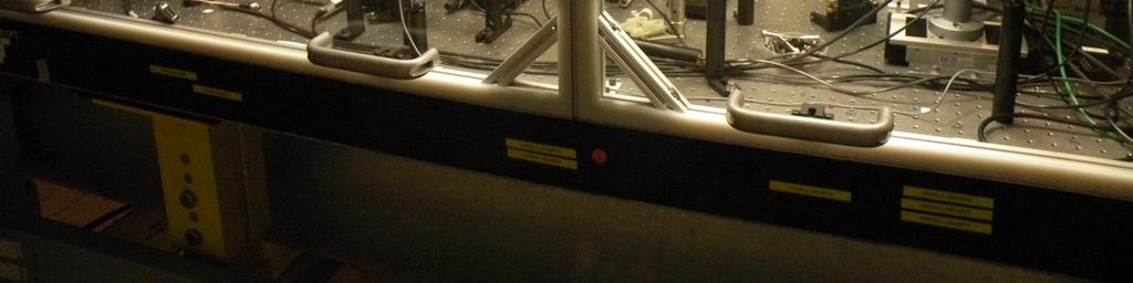
21 Upstream IP Table THz table Plasma oven Upstream IP table Downstream IP table 21

22 IP Tables 22


23 THz Table with Dry-Air Enclosure 23
24 Layout of the THz Table Michelson Interferometer Top View 1-µm Ti foil 1-µm Ti foil From bunch compressor CCD Visible Insertable silicon plate To IP THz Side View 24
25 Optics for the Upstream Foil Foil To Michelson OAP Knife edge Joulemeter 25
26 Michelson Interferometer Fixed mirror Scanning mirror Pyroelectric detector THz beamsplitter 26
27 Finding the Peak Electric Field Model the electric field at the focus with a simple Gaussian: This neglects the radial polarization and the negative lobes before and after peak x y z E E0exp x y z Then the energy in the pulse is related to the electric field by: U E dx dy dz E 2 3/ x y z Dependence on bunch charge q, bunch compression z : Field E 0 ~ q/ z Energy U 0 ~ E 02 z ~ q 2 / z Coherence: Less pulse energy, due to incoherent emission, for wavelengths x,y,z Measurements needed: Pulse energy U 0 Pyroelectric joulemeter and electron energy loss Pulse duration t = z /c Michelson interferometer Size at focus x,y Pyroelectric camera or knife-edge scans 27
28 Energy in a THz Pulse Joulemeters aren t black for THz Pyroelectric manufacturers provide rough correction factors of 2 to 4 LCLS: 200 to 400 µj, for 350 pc and 20 fs RMS (full compression) FACET: 460 µj, for 3 nc and 130 fs RMS (but with intermediate compression) Compare THz energy to electron energy loss when LCLS foil is inserted Beam dump serves as e spectrometer Transition radiation as beam enters, exits foil Entry THz goes through window Foil in 30% reflection loss on diamond Exit THz is not collected Measured loss: 2.9 mj for 350 pc and 20 fs So about 1 mj should be collected Calibration of THz joulemeter? Energy Loss (MeV) 8.7 MeV loss for 350 pc = 2.9 mj Foil out Repetitions 28
29 Bunch Profile: Finding the Form Factor Electric field E of a bunch of N electrons at positions t j : N i tj E( t) E ( t t ) E( ) E ( ) e j 1 1 j 1 where E 1 is the field of one electron. Energy in the pulse is related to the longitudinal form factor f( ): 2 2 d 2 i t 2 d j ( ) 1( ) 1( ) ( ) 2 j 2 U dte t E e N E f Interferometer gives the pulse energy in an autocorrelation with a delay : d 2 2 i U( ) U0 Re E1( ) f( ) e 2 The power spectrum U( ) is then (neglecting the DC component): 2 2 U( ) E ( ) f( ) E 1 is essentially constant at THz frequencies, and so U( ) gives us f( ) 2. 1 j 29

30 Michelson Interferometer Scans LCLS FACET 30

31 Michelson Spectra LCLS FACET Spectral width depends on bunch compression LCLS bunches are usually shorter and so have higher THz frequencies Reflections from detector layers modulate the spectra 31
 1 exp 2 2 hp 0 Filter causes the negative dips about")

32 Restoring Low Frequencies Finite size of beampipe and window remove low-frequency components Must compensate for filtering to get longitudinal bunch profile from the spectrum Model the low-frequency loss as a high-pass filter attenuating the field by: F ( ) 1 exp 2 2 hp 0 Filter causes the negative dips about the central interference peak in the time domain Fit region with filtered Gaussian beam to find 0 Then discard Gaussian assumption, but keep 0 Spectral compensation: Divide spectrum by filter function F hp Fit a parabola near f = 0, where 1/ F hp diverges Bunch reconstruction isn t very sensitive to this region 32
 is causal, the Kramers-Kronig relations give: 2 ln ( ) ( ) ( ) P d 2 2 0 The magnitude ( ) and phase ( ) then let us compute the bunch profile f(t).")
33 Kramers-Kronig Retrieval of the Phase and Profile If we express f( ) in terms of its magnitude ( ) and phase ( ), then: ln f( ) ln ( ) i ( ) Since ln and are real and f(t) is causal, the Kramers-Kronig relations give: 2 ln ( ) ( ) ( ) P d The magnitude ( ) and phase ( ) then let us compute the bunch profile f(t). 33

34 Profiles at Three Bunch Compressions High Compression Medium Compression Low Compression 34
35 Transverse Size at the THz Focus LCLS Pyroelectric camera LCLS pyroelectric camera: Pixel size = 100 µm Spot size 500 µm FWHM 200 µm RMS FACET knife-edge scans: x = 1.4 mm RMS, y = 1.1 mm RMS Why is the size at FACET much larger? FACET Knife-edge scans Horizontal Profile Vertical Profile 35


36 Standard Electron Optics near THz Table Large x beam size at THz table lowers pulse energy Beam size minimum is at experimental IP 36
37 Transverse e-beam Size Simulated beam with standard optics: x = 1.2 mm, y = 6 µm Measured with optical transition radiation 37
 Circular 85 x 85 µm 2 Elliptical 1200 x 6 µm 2 /c (mm 1 ) 38")
38 Double Waist to Reduce Transverse e-beam Size Simulation Comparing standard optics to a circular 85-µm beam Double-Waist optics Focus remains at IP, but x size at foil is reduced to x = 317 µm, y = 36 µm But an even smaller x would help, since the spectrum peaks at 1 THz (300 µm) Circular 85 x 85 µm 2 Elliptical 1200 x 6 µm 2 /c (mm 1 ) 38
39 Peak Electric Field LCLS Charge: q = 0.35 nc Energy: 100 U µj Size: x,y = 200 µm Length: 6 z 7 µm Electric and magnetic fields: 2.7 E 5.8 GV/m = 0.6 V/Å 9 B 19 T Quasi-half-cycle pulse Broad spectrum peaking at 10 THz FACET Charge: q = 3 nc Energy: 400 U µj Size: x = 1.4 mm, y = 1.1 mm Length: 20 z 40 µm Electric and magnetic fields: 0.36 E 0.68 GV/m = 0.07 V/Å 1.2 B 2.3 T Quasi-half-cycle pulse Broad spectrum peaking at 1 THz Higher fields should be possible with a smaller x at the foil 39
40 Detector Response THz detectors are poorly calibrated and are not spectrally flat Significant etalon effects (reflections from detector layers) Infratec has strong modulation Dip in response near 0.8 THz cuts out part of spectrum Not suitable for interferometer Compare to model (Henrik Loos) Compression: Low Medium High Detector Model Gentec has thinner layers 60-GHz modulation When 60 GHz is filtered, 240 GHz becomes visible Better, but not ideal Unfiltered Filtered 40


41 Water Vapor Before and after adding the dry-air enclosure at FACET Comparison to transmission through 1 m of humid air Without dry-air enclosure Dips near 0.75 and 1.2 THz 3 bunch compressor settings With dry-air enclosure Much improved, but there may still be some absorption Plan to improve the dry-air purge Compression: Low Medium High Humid air 41

42 Initial Concept: THz Pump and X-Ray Probe Bragg crystals delay the x-ray probe with a U-turn, so that they arrive at the sample after the THz pump. 42
43 Thin versus Thick Crystal Initial concept used a silicon crystal etched to 8 µm in center Advantage: In-band x rays diffract, but out-of-band x rays pass through Would permit parasitic operation Disadvantages: Electrons also pass through crystal Crystal must be thin to reduce hard radiation in user hutches downstream Heat deposited by x rays generates acoustic wave in the thin membrane Vibration disrupts Bragg diffraction Weak damping restricts operation to 1 Hz Newer concept uses thicker (100 µm) crystal with electron chicane Advantages: Electrons travel around crystal: No hard radiation Vibrations damped by clamping crystal to support Disadvantage: Not suitable for parasitic use 43

44 Concept: THz Pump and X-Ray Probe 44
45 Advantages and Disadvantages Advantages: Single bunch makes both THz and x-rays: No jitter No long transport line: Lower cost and no jitter from vibrating parts 3 Si crystals at 45 ±2.5 span photon energies from 7.59 to 9.56 kev Disadvantages: Undulator Hall would become an awkward user hutch Limited time for experimental setup: One shift every two weeks Access during run is possible, but slow: Insert e-beam stopper after linac Narrow diffraction bandwidth reduces x-ray energy Better match for narrow FEL bandwidth from hard x-ray self seeding Soft x rays are more difficult Multilayer mirrors, not crystals, needed to turn beam through 180 Usually reflectivity is low (away from grazing) and bandwidth is narrow To avoid absorption, x rays must not hit foil: Stronger chicane dipoles Must place sample in vacuum rather than dry air 45
46 Three Silicon Crystals Span a 2-keV Range Silicon Lattice Planes Energy (kev) at Angle (deg) h k l
47 Concept: Multilayer Mirror for Soft X Rays Reflectivity for S polarization of a calculated multilayer mirror 150 layers of 0.82-nm Cr on 1.13-nm Ti Suitable only over a narrow energy range Reflectivity versus Energy at 45 Incidence Reflectivity versus Angle for 450-eV Photons 47
48 Concept: THz Transport up to Klystron Gallery Transport THz from foil to an optical table in the Klystron Gallery 19-m path, including an 8-m vertical section through a penetration Characterize pulse before and after transport: energy, focus, spectrum Severe diffraction at these long wavelengths Large-diameter mirrors and tubing: 200 mm (8 inches) Frequent refocusing with off-axis parabolic (OAP) or toroidal mirrors Under vacuum to avoid water vapor or convection (UHV unnecessary) Hope for approval and funding in 2013 Future concept: Add 20 m to bring THz to Sector-20 laser hutch Location of new FACET laser, synchronized with electrons To pre-ionize the plasma for studies of plasma-wakefield acceleration Space for THz user experiments, including THz pump and laser probe 48


49 Concept: Transport Line at Top of Penetration Pumping flange Flange with mirror mount Alignment viewport View HeNe alignment beam directly or with a camera Bellows Flexibility Breaks up reflections from pipe wall 200-mm (8-inch) tubing 49
50 Concept: THz Transport to the NEH From Undulator Hall to Near Experimental Hall 100 m THz can t be transported along a straight path THz arrives 50 to 100 ns after x rays Probe/pump instead of pump/probe Remedy: Two electron bunches First bunch is optimized for THz High bunch charge and peak compression Second bunch, 100 ns later, makes x rays in the FEL Bunch charge and compression set to user s preference Integer number of RF buckets plus an optical trombone delay determines pump/probe spacing LCLS tested two bunches with 8.4-ns spacing in 2010 Now planning more tests with variable spacing 50
51 2 Bunches = 4 Pulses Each bunch emits both x rays and THz Arrival order: X ray 1, THz 1, X ray 2, THz 2 Early x-ray pulse interferes with pump-probe measurements Also, final THz pulse after pump-probe might be a problem Remedy: Suppress lasing by the first bunch High charge and full compression High laser-heater energy for first bunch Kicker to make first bunch oscillate in the undulator But the first bunch emits spontaneous in the undulator Could interfere with some experiments 51
52 Concept: Bypass Beamline for the THz Bunch Add a fast kicker before the undulator, sending bunch into a bypass 1 st bunch goes through bypass, parallel to undulator Put THz foil in the bypass Bunch makes THz but no x rays 2 nd bunch goes through the FEL Bunch makes x rays but no THz No trailing THz pulse after pump/probe Soft x rays are not absorbed by foil 52
53 Concept: THz for LCLS-2 Two bunches in each 120-Hz pulse Two ways to share them: Bunch 1 to Undulator 1, Bunch 2 to Undulator 2 Each user gets 120-Hz x rays, without THz Bunch 1 to bypass, Bunch 2 alternates between undulators Each user gets THz and x rays at 60 Hz 53
54 Comparing THz at LCLS and FACET LCLS FACET Location 30 m past undulator 10 m before FACET IP Source CTR from 10-µm Be foil CTR from 1-µm Ti foil Beam(s) Both electrons and x rays Electrons only Bunch length 20 fs RMS 65 fs RMS THz spectrum 3 30 THz THz THz electric field 6 GV/m 0.7 GV/m Pulse energy 400 µj µj Access to tunnel 8 hours every 2 weeks 8 hours every week Transport line Requires 100-m transport line and 2 e bunches. No plans now. 20-m line to Gallery possible in May extend to hutch later. Future concepts THz pump and x-ray probe Easy access to THz in a hutch 54
55 Summary Present capabilities: Intense, broadband, quasi-half-cycle, THz pulses produced by coherent transition radiation at LCLS and FACET The two sources are complementary: Shared instrumentation development Same potential user community Future concepts include: THz pump and x-ray probe, on a single table and with a single bunch Transport line to a hutch at FACET These ideas come with limitations in cost, access, and beam time. In planning the future role of THz here, SLAC will be guided by your ideas. Tell us where you see exciting opportunities in THz science, and what unique capabilities SLAC could offer to pursue them. 55
SPPS: The SLAC Linac Bunch Compressor and Its Relevance to LCLS
 LCLS Technical Advisory Committee December 10-11, 2001. SPPS: The SLAC Linac Bunch Compressor and Its Relevance to LCLS Patrick Krejcik LCLS Technical Advisory Committee Report 1: July 14-15, 1999 The
II) Experimental Design
 Experimental Design") SLAC Experimental Advisory Committee --- September 12 th, 1997 II) Experimental Design Theory and simulations Great promise of significant scientific and technological achievements! How to realize this
SLAC Experimental Advisory Committee --- September 12 th, 1997 II) Experimental Design Theory and simulations Great promise of significant scientific and technological achievements! How to realize this
Experimental Optimization of Electron Beams for Generating THz CTR and CDR with PITZ
 Experimental Optimization of Electron Beams for Generating THz CTR and CDR with PITZ Introduction Outline Optimization of Electron Beams Calculations of CTR/CDR Pulse Energy Summary & Outlook Prach Boonpornprasert
Short Pulse, Low charge Operation of the LCLS. Josef Frisch for the LCLS Commissioning Team
 Short Pulse, Low charge Operation of the LCLS Josef Frisch for the LCLS Commissioning Team 1 Normal LCLS Parameters First Lasing in April 10, 2009 Beam to AMO experiment August 18 2009. Expect first user
Observation of Coherent Optical Transition Radiation in the LCLS Linac
 Observation of Coherent Optical Transition Radiation in the LCLS Linac Henrik Loos, Ron Akre, Franz-Josef Decker, Yuantao Ding, David Dowell, Paul Emma,, Sasha Gilevich, Gregory R. Hays, Philippe Hering,
Free-electron laser SACLA and its basic. Yuji Otake, on behalf of the members of XFEL R&D division RIKEN SPring-8 Center
 Free-electron laser SACLA and its basic Yuji Otake, on behalf of the members of XFEL R&D division RIKEN SPring-8 Center Light and Its Wavelength, Sizes of Material Virus Mosquito Protein Bacteria Atom
X-Ray Diagnostics Commissioning at the LCLS
 X-Ray Diagnostics Commissioning at the LCLS - Selected Studies - J. Welch, SLAC National Accelerator Laboratory Aug. 3-27, 2010 Commissioning Studies Microbunching Instability Laser Heater tune-up Gas
4 FEL Physics. Technical Synopsis
 4 FEL Physics Technical Synopsis This chapter presents an introduction to the Free Electron Laser (FEL) physics and the general requirements on the electron beam parameters in order to support FEL lasing
Linac Based Photon Sources: XFELS. Coherence Properties. J. B. Hastings. Stanford Linear Accelerator Center
 Linac Based Photon Sources: XFELS Coherence Properties J. B. Hastings Stanford Linear Accelerator Center Coherent Synchrotron Radiation Coherent Synchrotron Radiation coherent power N 6 10 9 incoherent
CONCEPTUAL STUDY OF A SELF-SEEDING SCHEME AT FLASH2
 CONCEPTUAL STUDY OF A SELF-SEEDING SCHEME AT FLASH2 T. Plath, L. L. Lazzarino, Universität Hamburg, Hamburg, Germany K. E. Hacker, T.U. Dortmund, Dortmund, Germany Abstract We present a conceptual study
FACET-II Design Update
 FACET-II Design Update October 17-19, 2016, SLAC National Accelerator Laboratory Glen White FACET-II CD-2/3A Director s Review, August 9, 2016 Planning for FACET-II as a Community Resource FACET-II Photo
LOLA: Past, present and future operation
 LOLA: Past, present and future operation FLASH Seminar 1/2/29 Christopher Gerth, DESY 8/5/29 FLASH Seminar Christopher Gerth 1 Outline Past Present Future 8/5/29 FLASH Seminar Christopher Gerth 2 Past
Developments for the FEL user facility
 Developments for the FEL user facility J. Feldhaus HASYLAB at DESY, Hamburg, Germany Design and construction has started for the FEL user facility including the radiation transport to the experimental
Generation and characterization of ultra-short electron and x-ray x pulses
 Generation and characterization of ultra-short electron and x-ray x pulses Zhirong Huang (SLAC) Compact XFEL workshop July 19-20, 2010, Shanghai, China Ultra-bright Promise of XFELs Ultra-fast LCLS Methods
3. Synchrotrons. Synchrotron Basics
 1 3. Synchrotrons Synchrotron Basics What you will learn about 2 Overview of a Synchrotron Source Losing & Replenishing Electrons Storage Ring and Magnetic Lattice Synchrotron Radiation Flux, Brilliance
Tuning Techniques And Operator Diagnostics for FACET at SLAC National Accelerator Laboratory. Chris Melton SLAC Accelerator Operations
 Tuning Techniques And Operator Diagnostics for FACET at SLAC National Accelerator Laboratory Chris Melton SLAC Accelerator Operations FACET Tuning And Diagnostics What is FACET? FACET Performance Challenges
Microbunching Workshop 2010 March 24, 2010, Frascati, Italy. Zhirong Huang
 Measurements of the LCLS Laser Heater and its impact on the LCLS FEL Performance Z. Huang for the LCLS commissioning team LCLS 1 1 Outline Introduction LCLS setup and measurements Effects on FEL performance
Flexible control of femtosecond pulse duration and separation using an emittance-spoiling foil in x-ray free-electron lasers
 SLAC PUB 16312 June 2015 Flexible control of femtosecond pulse duration and separation using an emittance-spoiling foil in x-ray free-electron lasers Y. Ding 1, C. Behrens 2, R. Coffee 1, F.-J. Decker
Low slice emittance preservation during bunch compression
 Low slice emittance preservation during bunch compression S. Bettoni M. Aiba, B. Beutner, M. Pedrozzi, E. Prat, S. Reiche, T. Schietinger Outline. Introduction. Experimental studies a. Measurement procedure
FURTHER UNDERSTANDING THE LCLS INJECTOR EMITTANCE*
 Proceedings of FEL014, Basel, Switzerland FURTHER UNDERSTANDING THE LCLS INJECTOR EMITTANCE* F. Zhou, K. Bane, Y. Ding, Z. Huang, and H. Loos, SLAC, Menlo Park, CA 9405, USA Abstract Coherent optical transition
FLASH overview. Nikola Stojanovic. PIDID collaboration meeting, Hamburg,
 FLASH overview Nikola Stojanovic PIDID collaboration meeting, Hamburg, 16.12.2011 Outline Overview of the FLASH facility Examples of research at FLASH Nikola Stojanovic PIDID: FLASH overview Hamburg, December
Check the LCLS Project website to verify 2 of 6 that this is the correct version prior to use.
 1. Introduction The XTOD Offset Systems are designed to spatially separate the useful FEL radiation from high-energy spontaneous radiation and Bremsstrahlung γ-rays. These unwanted radiations are generated
R&D experiments at BNL to address the associated issues in the Cascading HGHG scheme
 R&D experiments at BNL to address the associated issues in the Cascading HGHG scheme Li Hua Yu for DUV-FEL Team National Synchrotron Light Source Brookhaven National Laboratory FEL2004 Outline The DUVFEL
SUPPLEMENTARY INFORMATION
 doi:10.1038/nature10721 Experimental Methods The experiment was performed at the AMO scientific instrument 31 at the LCLS XFEL at the SLAC National Accelerator Laboratory. The nominal electron bunch charge
Operational Performance of LCLS Beam Instrumentation. Henrik Loos, SLAC BIW 2010, Santa Fe, NM
 Editor's Note: PDF version of slides from Beam Instrumentation Workshop 21, Santa Fe, NM Operational Performance of LCLS Beam Instrumentation Henrik Loos, SLAC BIW 21, Santa Fe, NM BIW 21 1 1 Henrik Loos
Compressor and Chicane Radiation Studies at the ATF. Gerard Andonian, UCLA High Power Workshop January 14-16, 2009 UCLA
 Compressor and Chicane Radiation Studies at the ATF Gerard Andonian, UCLA High Power Workshop January 14-16, 2009 UCLA Collaboration UCLA PBPL G. Andonian, A. Cook, M. Dunning, E. Hemsing, A. Murokh, S.
Two-Stage Chirped-Beam SASE-FEL for High Power Femtosecond X-Ray Pulse Generation
 Two-Stage Chirped-Beam SASE-FEL for High ower Femtosecond X-Ray ulse Generation C. Schroeder*, J. Arthur^,. Emma^, S. Reiche*, and C. ellegrini* ^ Stanford Linear Accelerator Center * UCLA 12-10-2001 LCLS-TAC
SPARCLAB. Source For Plasma Accelerators and Radiation Compton. On behalf of SPARCLAB collaboration
 SPARCLAB Source For Plasma Accelerators and Radiation Compton with Laser And Beam On behalf of SPARCLAB collaboration EMITTANCE X X X X X X X X 2 BRIGHTNESS (electrons) B n 2I nx ny A m 2 rad 2 The current
Brightness and Coherence of Synchrotron Radiation and Free Electron Lasers. Zhirong Huang SLAC, Stanford University May 13, 2013
 Brightness and Coherence of Synchrotron Radiation and Free Electron Lasers Zhirong Huang SLAC, Stanford University May 13, 2013 Introduction GE synchrotron (1946) opened a new era of accelerator-based
Femtosecond X-ray Pulse Temporal Characterization in Free-Electron Lasers Using a Transverse Deflector. Abstract
 SLAC PUB 14534 September 2011 Femtosecond X-ray Pulse Temporal Characterization in Free-Electron Lasers Using a Transverse Deflector Y. Ding 1, C. Behrens 2, P. Emma 1, J. Frisch 1, Z. Huang 1, H. Loos
X-ray Free-electron Lasers
 X-ray Free-electron Lasers Ultra-fast Dynamic Imaging of Matter II Ischia, Italy, 4/30-5/3/ 2009 Claudio Pellegrini UCLA Department of Physics and Astronomy Outline 1. Present status of X-ray free-electron
LCLS Accelerator Parameters and Tolerances for Low Charge Operations
 LCLS-TN-99-3 May 3, 1999 LCLS Accelerator Parameters and Tolerances for Low Charge Operations P. Emma SLAC 1 Introduction An option to control the X-ray FEL output power of the LCLS [1] by reducing the
A Meter-Scale Plasma Wakefield Accelerator
 A Meter-Scale Plasma Wakefield Accelerator Rasmus Ischebeck, Melissa Berry, Ian Blumenfeld, Christopher E. Clayton, Franz-Josef Decker, Mark J. Hogan, Chengkun Huang, Richard Iverson, Chandrashekhar Joshi,
Diagnostic Systems for Characterizing Electron Sources at the Photo Injector Test Facility at DESY, Zeuthen site
 1 Diagnostic Systems for Characterizing Electron Sources at the Photo Injector Test Facility at DESY, Zeuthen site Sakhorn Rimjaem (on behalf of the PITZ team) Motivation Photo Injector Test Facility at
Demonstration of Energy-Chirp Control in Relativistic Electron Bunches at LCLS Using a Corrugated Structure. Karl Bane, 7 April 2017,, KEK
 Demonstration of Energy-Chirp Control in Relativistic Electron Bunches at LCLS Using a Corrugated Structure Karl Bane, 7 April 2017,, KEK Introduction At the end of acceleration in an X-ray FEL, the beam
Beam Echo Effect for Generation of Short Wavelength Radiation
 Beam Echo Effect for Generation of Short Wavelength Radiation G. Stupakov SLAC NAL, Stanford, CA 94309 31st International FEL Conference 2009 Liverpool, UK, August 23-28, 2009 1/31 Outline of the talk
OPTIMIZATION OF COMPENSATION CHICANES IN THE LCLS-II BEAM DELIVERY SYSTEM
 OPTIMIZATION OF COMPENSATION CHICANES IN THE LCLS-II BEAM DELIVERY SYSTEM LCLS-II TN-15-41 11/23/2015 J. Qiang, M. Venturini November 23, 2015 LCLSII-TN-15-41 1 Introduction L C L S - I I T E C H N I C
How Does It All Work? A Summary of the IDEAS Beamline at the Canadian Light Source
 How Does It All Work? A Summary of the IDEAS Beamline at the Canadian Light Source What Makes Up The Canadian Light Source? 4. Storage Ring 5. Synchrotron Light 6. Beamline 1. Electron Gun 2. Linear Accelerator
Opportunities and Challenges for X
 Opportunities and Challenges for X -ray Free Electron Lasers for X-ray Ultrafast Science J. Hastings Stanford Linear Accelerator Center June 22, 2004 European XFEL Laboratory How Short is short? defined
Vertical Polarization Option for LCLS-II. Abstract
 SLAC National Accelerator Lab LCLS-II TN-5-8 March 5 Vertical Polarization Option for LCLS-II G. Marcus, T. Raubenheimer SLAC, Menlo Park, CA 95 G. Penn LBNL, Berkeley, CA 97 Abstract Vertically polarized
Short Bunch Length Measurements
 CAS T. Lefevre Short Bunch Length Measurements What is short? Why short Bunches? How do we produce them? How do we measure them? What is short? When you are courting a nice girl an hour seems like a second.
Jitter measurement by electro-optical sampling
 Jitter measurement by electro-optical sampling VUV-FEL at DESY - Armin Azima S. Duesterer, J. Feldhaus, H. Schlarb, H. Redlin, B. Steffen, DESY Hamburg K. Sengstock, Uni Hamburg Adrian Cavalieri, David
Linac Driven Free Electron Lasers (III)
") Linac Driven Free Electron Lasers (III) Massimo.Ferrario@lnf.infn.it SASE FEL Electron Beam Requirements: High Brightness B n ( ) 1+ K 2 2 " MIN r #$ % &B! B n 2 n K 2 minimum radiation wavelength energy
Linac Driven Free Electron Lasers (III) Massimo.Ferrario@lnf.infn.it SASE FEL Electron Beam Requirements: High Brightness B n ( ) 1+ K 2 2 " MIN r #$ % &B! B n 2 n K 2 minimum radiation wavelength energy
X-band Experience at FEL
 X-band Experience at FERMI@Elettra FEL Gerardo D Auria Elettra - Sincrotrone Trieste GdA_TIARA Workshop, Ångström Laboratory, June 17-19, 2013 1 Outline The FERMI@Elettra FEL project Machine layout and
SPARCLAB. Source For Plasma Accelerators and Radiation Compton with Laser And Beam
 SPARCLAB Source For Plasma Accelerators and Radiation Compton with Laser And Beam EMITTANCE X X X X X X X X Introduction to SPARC_LAB 2 BRIGHTNESS (electrons) B n 2I nx ny A m 2 rad 2 The current can be
Radiological safety studies for the TeraFERMI beamline at
 Radiological safety studies for the TeraFERMI beamline at FERMI@elettra K.Casarin 1, L. Fröhlich 2, G.Tromba 1, A.Vascotto 1 1 Elettra - Sincrotrone Trieste S.C.p.A., Trieste, Italy 2 Deutsches Elektronen-Synchrotron
An Adventure in Marrying Laser Arts and Accelerator Technologies
 An Adventure in Marrying Laser Arts and Accelerator Technologies Dao Xiang Beam Physics Dept, SLAC, Stanford University Feb-28-2012 An example sample Probe (electron) Pump (laser) Typical pump-probe experiment
Measurement of wakefields in hollow plasma channels Carl A. Lindstrøm (University of Oslo)
") Measurement of wakefields in hollow plasma channels Carl A. Lindstrøm (University of Oslo) in collaboration with Spencer Gessner (CERN) presented by Erik Adli (University of Oslo) FACET-II Science Workshop
Measurement of wakefields in hollow plasma channels Carl A. Lindstrøm (University of Oslo) in collaboration with Spencer Gessner (CERN) presented by Erik Adli (University of Oslo) FACET-II Science Workshop
Coherent Cherenkov radiation from ultra-short electron bunch passing through vacuum channel in conical target
 Coherent Cherenkov radiation from ultra-short electron bunch passing through vacuum channel in conical target A.P. Potylitsyn, S.Yu. Gogolev RREPS_11, London, 2011, Sept.12-16 Motivation Existing experimental
LCLS-II SCRF start-to-end simulations and global optimization as of September Abstract
 SLAC National Accelerator Lab LCLS-II TN-17-4 February 217 LCLS-II SCRF start-to-end simulations and global optimization as of September 216 G. Marcus SLAC, Menlo Park, CA 9425 J. Qiang LBNL, Berkeley,
Radiation Safety at LCLS: The Photon Beam s Maximum Capability and Material Damage Potential
 SLAC-PUB-15708 August 2013 Radiation Safety at LCLS: The Photon Beam s Maximum Capability and Material Damage Potential J.M. Bauer *1, J.C. Liu 1, A.A. Prinz 2, and S.H. Rokni 1 1 Radiation Protection
SLS at the Paul Scherrer Institute (PSI), Villigen, Switzerland
, Villigen, Switzerland") SLS at the Paul Scherrer Institute (PSI), Villigen, Switzerland Michael Böge 1 SLS Team at PSI Michael Böge 2 Layout of the SLS Linac, Transferlines Booster Storage Ring (SR) Beamlines and Insertion Devices
SLS at the Paul Scherrer Institute (PSI), Villigen, Switzerland Michael Böge 1 SLS Team at PSI Michael Böge 2 Layout of the SLS Linac, Transferlines Booster Storage Ring (SR) Beamlines and Insertion Devices
Simulations of the IR/THz Options at PITZ (High-gain FEL and CTR)
") Case Study of IR/THz source for Pump-Probe Experiment at the European XFEL Simulations of the IR/THz Options at PITZ (High-gain FEL and CTR) Introduction Outline Simulations of High-gain FEL (SASE) Simulation
Case Study of IR/THz source for Pump-Probe Experiment at the European XFEL Simulations of the IR/THz Options at PITZ (High-gain FEL and CTR) Introduction Outline Simulations of High-gain FEL (SASE) Simulation
FEL SIMULATION AND PERFORMANCE STUDIES FOR LCLS-II
 FEL SIMULATION AND PERFORMANCE STUDIES FOR LCLS-II G. Marcus, Y. Ding, P. Emma, Z. Huang, T. Raubenheimer, L. Wang, J. Wu SLAC, Menlo Park, CA 9, USA Abstract The design and performance of the LCLS-II
Linear Collider Collaboration Tech Notes
 LCC 0035 07/01/00 Linear Collider Collaboration Tech Notes More Options for the NLC Bunch Compressors January 7, 2000 Paul Emma Stanford Linear Accelerator Center Stanford, CA Abstract: The present bunch
INVESTIGATIONS OF THE DISTRIBUTION IN VERY SHORT ELECTRON BUNCHES LONGITUDINAL CHARGE
 INVESTIGATIONS OF THE LONGITUDINAL CHARGE DISTRIBUTION IN VERY SHORT ELECTRON BUNCHES Markus Hüning III. Physikalisches Institut RWTH Aachen IIIa and DESY Invited talk at the DIPAC 2001 Methods to obtain
Femto-second FEL Generation with Very Low Charge at LCLS
 Femto-second FEL Generation with Very Low Charge at LCLS Yuantao Ding, For the LCLS commissioning team X-ray Science at the Femtosecond to Attosecond Frontier workshop May 18-20, 2009, UCLA SLAC-PUB-13525;
SL_COMB. The SL_COMB experiment at SPARC_LAB will operate in the so-called quasinonlinear regime, defined by the dimensionless charge quantity
 SL_COMB E. Chiadroni (Resp), D. Alesini, M. P. Anania (Art. 23), M. Bellaveglia, A. Biagioni (Art. 36), S. Bini (Tecn.), F. Ciocci (Ass.), M. Croia (Dott), A. Curcio (Dott), M. Daniele (Dott), D. Di Giovenale
THz Electron Gun Development. Emilio Nanni 3/30/2016
 THz Electron Gun Development Emilio Nanni 3/30/2016 Outline Motivation Experimental Demonstration of THz Acceleration THz Generation Accelerating Structure and Results Moving Forward Parametric THz Amplifiers
Femtosecond Width X-ray Generation with the SLAC Linac and the FFTB Beamline *
 SLAC-PUB-8858 June 1 Femtosecond Width X-ray Generation with the SLAC Linac and the FFTB Beamline * P. Krejcik, J. Arthur, R. Carr, M. Cornacchia, P. Emma, R. Iverson, J. Safranek, R. Tatchyn. Stanford
O rion. The ORION Facility at SLAC. Bob Siemann AAC Workshop, June 15, 2000
 The ORION Facility at SLAC Bob Siemann AAC Workshop, June 15, 2000 1. Introduction 2. The ORION Workshop 3. What s Next? 4. Concluding Remarks http://www-project.slac.stanford.edu/orion/ Introduction Advanced
Hiromitsu TOMIZAWA XFEL Division /SPring-8
 TUPLB10 (Poster: TUPB080) Non-destructive Real-time Monitor to measure 3D- Bunch Charge Distribution with Arrival Timing to maximize 3D-overlapping for HHG-seeded EUV-FEL Hiromitsu TOMIZAWA XFEL Division
FLASH/DESY, Hamburg. Jörg Rossbach University of Hamburg & DESY, Germany - For the FLASH Team -
 First Lasing below 7nm Wavelength at FLASH/DESY, Hamburg Jörg Rossbach University of Hamburg & DESY, Germany - For the FLASH Team - email: joerg.rossbach@desy.de FLASH: The first FEL user facility for
The MID instrument.
 The MID instrument International Workshop on the Materials Imaging and Dynamics Instrument at the European XFEL Grenoble, Oct 28/29, 2009 Thomas Tschentscher thomas.tschentscher@xfel.eu Outline 2 History
MaRIE. MaRIE X-Ray Free-Electron Laser Pre-Conceptual Design
 Operated by Los Alamos National Security, LLC, for the U.S. Department of Energy MaRIE (Matter-Radiation Interactions in Extremes) MaRIE X-Ray Free-Electron Laser Pre-Conceptual Design B. Carlsten, C.
Electron Spectrometer for FLASHForward Plasma-Wakefield Accelerator
 Electron Spectrometer for FLASHForward Plasma-Wakefield Accelerator Artemis Kontogoula Supervisor: Vladyslav Libov September 7, 2017 National & Kapodistrian University of Athens, Greece Deutsches Elektronen-Synchrotron
Coherent THz Pulses: Source and Science at the NSLS
 Coherent THz Pulses: Source and Science at the NSLS H. Loos, B. Sheehy, D. Arena, J.B. Murphy, X.-J. Wang and G. L. Carr Brookhaven National Laboratory carr@bnl.gov http://www.nsls.bnl.gov http://infrared.nsls.bnl.gov
Excitements and Challenges for Future Light Sources Based on X-Ray FELs
 Excitements and Challenges for Future Light Sources Based on X-Ray FELs 26th ADVANCED ICFA BEAM DYNAMICS WORKSHOP ON NANOMETRE-SIZE COLLIDING BEAMS Kwang-Je Kim Argonne National Laboratory and The University
Harmonic Lasing Self-Seeded FEL
 Harmonic Lasing Self-Seeded FEL E. Schneidmiller and M. Yurkov FEL seminar, DESY Hamburg June 21, 2016 In a planar undulator (K ~ 1 or K >1) the odd harmonics can be radiated on-axis (widely used in SR
Excitements and Challenges for Future Light Sources Based on X-Ray FELs
 Excitements and Challenges for Future Light Sources Based on X-Ray FELs 26th ADVANCED ICFA BEAM DYNAMICS WORKSHOP ON NANOMETRE-SIZE COLLIDING BEAMS Kwang-Je Kim Argonne National Laboratory and The University
Layout of the HHG seeding experiment at FLASH
 Layout of the HHG seeding experiment at FLASH V. Miltchev on behalf of the sflash team: A. Azima, J. Bödewadt, H. Delsim-Hashemi, M. Drescher, S. Düsterer, J. Feldhaus, R. Ischebeck, S. Khan, T. Laarmann
Transverse Coherence Properties of the LCLS X-ray Beam
 LCLS-TN-06-13 Transverse Coherence Properties of the LCLS X-ray Beam S. Reiche, UCLA, Los Angeles, CA 90095, USA October 31, 2006 Abstract Self-amplifying spontaneous radiation free-electron lasers, such
LCLS-II Conceptual Design Review. 6 Accelerator
 6 Accelerator Technical Synopsis In order for the Self Amplified Spontaneous Emission (SASE) Free Electron Laser (FEL) to operate in saturation, a high electron peak current with small transverse and longitudinal
X-band RF driven hard X-ray FELs. Yipeng Sun ICFA Workshop on Future Light Sources March 5-9, 2012
 X-band RF driven hard X-ray FELs Yipeng Sun ICFA Workshop on Future Light Sources March 5-9, 2012 Motivations & Contents Motivations Develop more compact (hopefully cheaper) FEL drivers, L S C X-band (successful
Femtosecond and sub-femtosecond x-ray pulses from a SASE-based free-electron laser. Abstract
 SLAC-PUB-12 Femtosecond and sub-femtosecond x-ray pulses from a SASE-based free-electron laser P. Emma, K. Bane, M. Cornacchia, Z. Huang, H. Schlarb, G. Stupakov, and D. Walz Stanford Linear Accelerator
Linac optimisation for the New Light Source
 Linac optimisation for the New Light Source NLS source requirements Electron beam requirements for seeded cascade harmonic generation LINAC optimisation (2BC vs 3 BC) CSR issues energy chirp issues jitter
AWAKE: The Proton Driven Plasma Wakefield Acceleration Experiment at CERN. Alexey Petrenko on behalf of the AWAKE Collaboration
 AWAKE: The Proton Driven Plasma Wakefield Acceleration Experiment at CERN Alexey Petrenko on behalf of the AWAKE Collaboration Outline Motivation AWAKE at CERN AWAKE Experimental Layout: 1 st Phase AWAKE
First operation of a Harmonic Lasing Self-Seeded FEL
 First operation of a Harmonic Lasing Self-Seeded FEL E. Schneidmiller and M. Yurkov ICFA workshop, Arcidosso, Italy, 22.09.2017 Outline Harmonic lasing Harmonic lasing self-seeded (HLSS) FEL Experiments
Set-up for ultrafast time-resolved x-ray diffraction using a femtosecond laser-plasma kev x-ray-source
 Set-up for ultrafast time-resolved x-ray diffraction using a femtosecond laser-plasma kev x-ray-source C. Blome, K. Sokolowski-Tinten *, C. Dietrich, A. Tarasevitch, D. von der Linde Inst. for Laser- and
Diagnostic Systems for High Brightness Electron Injectors
 Diagnostic Systems for High Brightness Electron Injectors Henrik Loos 48 th ICFA Advanced Beam Dynamics Workshop on Future Light Sources SLAC 2010 1 1 Henrik Loos LCLS Injector Injector Diagnostics Characterize
LCLS Injector Prototyping at the GTF
 LCLS Injector Prototyping at at the GTF John John Schmerge, SLAC SLAC November 3, 3, 23 23 GTF GTF Description Summary of of Previous Measurements Longitudinal Emittance Transverse Emittance Active LCLS
LCLS Commissioning Status
 LCLS Commissioning Status Paul Emma (for the LCLS Commissioning Team) June 20, 2008 LCLS ANL LLNL UCLA FEL Principles Electrons slip behind EM wave by λ 1 per undulator period ( (λ u ) x K/γ e λ u v x
Echo-Enabled Harmonic Generation
 Echo-Enabled Harmonic Generation G. Stupakov SLAC NAL, Stanford, CA 94309 IPAC 10, Kyoto, Japan, May 23-28, 2010 1/29 Outline of the talk Generation of microbunching in the beam using the echo effect mechanism
LCLS Undulators Present Status and Future Upgrades
 LCLS Undulators Present Status and Future Upgrades Heinz-Dieter Nuhn LCLS Undulator Group Leader 1 1 Heinz-Dieter Nuhn Linac Coherent Light Source INJECTOR LINAC BEAM TRANSPORT UNDULATOR HALL 2 2 Heinz-Dieter
BUNCH LENGTH MEASUREMENT AT THE FERMILAB A0 PHOTOINJECTOR USING A MARTIN-PUPLETT INTERFEROMETER *
 BUNCH LENGTH MEASUREMENT AT THE FERMILAB A0 PHOTOINJECTOR USING A MARTIN-PUPLETT INTERFEROMETER * Randy Thurman-Keup #, Raymond Patrick Fliller, Grigory Kazakevich (Fermilab, P.O. Box 500, Batavia, Illinois
Experimental study of nonlinear laser-beam Thomson scattering
 Experimental study of nonlinear laser-beam Thomson scattering T. Kumita, Y. Kamiya, T. Hirose Department of Physics, Tokyo Metropolitan University, 1-1 Minami-Ohsawa, Hachioji, Tokyo 192-0397, Japan I.
Construction of a 100-TW laser and its applications in EUV laser, wakefield accelerator, and nonlinear optics
 Construction of a 100-TW laser and its applications in EUV laser, wakefield accelerator, and nonlinear optics Jyhpyng Wang ( ) Institute of Atomic and Molecular Sciences Academia Sinica, Taiwan National
Measurements of Short Bunches at SPPS and E-164X
 Measurements of Short Bunches at SPPS and E-164X P. Muggli (USC) M.J. Hogan, C.D. Barnes, D. Walz, R. Siemann P.J. Emma, P. Krejcik (SLAC) H. Schlarb, R. Ischebeck (DESY) P. Muggli, XFEL 24, SLAC 7/29/4
Beam Dynamics. Gennady Stupakov. DOE High Energy Physics Review June 2-4, 2004
 Beam Dynamics Gennady Stupakov DOE High Energy Physics Review June 2-4, 2004 Beam Dynamics Research in ARDA Broad expertise in many areas: lattice design, collective effects, electron cloud, beam-beam
VELA/CLARA as Advanced Accelerator Studies Test-bed at Daresbury Lab.
 VELA/CLARA as Advanced Accelerator Studies Test-bed at Daresbury Lab. Yuri Saveliev on behalf of VELA and CLARA teams STFC, ASTeC, Cockcroft Institute Daresbury Lab., UK Outline VELA (Versatile Electron
Research with Synchrotron Radiation. Part I
 Research with Synchrotron Radiation Part I Ralf Röhlsberger Generation and properties of synchrotron radiation Radiation sources at DESY Synchrotron Radiation Sources at DESY DORIS III 38 beamlines XFEL
THz field strength larger than MV/cm generated in organic crystal
 SwissFEL Wir schaffen Wissen heute für morgen 1 2 C. Vicario 1, R. Clemens 1 and C. P. Hauri 1,2 THz field strength larger than MV/cm generated in organic crystal 10/16/12 Workshop on High Field THz science
Inline Spectrometer as Permanent Optics at the X-ray Correlation Spectroscopy Instrument to Support Seeding Operation
 Inline Spectrometer as Permanent Optics at the X-ray Correlation Spectroscopy Instrument to Support Seeding Operation Amber L. Gray Office of Science, Science Undergraduate Laboratory Internship (SULI)
Fundamental investigation on CO 2 laser-produced Sn plasma for an EUVL source
 Fundamental investigation on CO 2 laser-produced Sn plasma for an EUVL source Yezheng Tao*, Mark Tillack, Kevin Sequoia, Russel Burdt, Sam Yuspeh, and Farrokh Najmabadi University of California, San Diego
ATTOSECOND X-RAY PULSES IN THE LCLS USING THE SLOTTED FOIL METHOD
 P. Emma et al. / Proceedings of the 24 FEL Conference, 333-338 333 ATTOSECOND X-RAY PULSES IN THE LCLS USING THE SLOTTED FOIL METHOD Abstract P. Emma, Z. Huang, SLAC, Stanford, CA 9439, USA M. Borland,
PAL LINAC UPGRADE FOR A 1-3 Å XFEL
 PAL LINAC UPGRADE FOR A 1-3 Å XFEL J. S. Oh, W. Namkung, Pohang Accelerator Laboratory, POSTECH, Pohang 790-784, Korea Y. Kim, Deutsches Elektronen-Synchrotron DESY, D-603 Hamburg, Germany Abstract With
ThomX Machine Advisory Committee. (LAL Orsay, March ) Ring Beam Dynamics
 Ring Beam Dynamics") ThomX Machine Advisory Committee (LAL Orsay, March 20-21 2017) Ring Beam Dynamics A. Loulergue, M. Biagini, C. Bruni, I. Chaikovska I. Debrot, N. Delerue, A. Gamelin, H. Guler, J. Zang Programme Investissements
ThomX Machine Advisory Committee (LAL Orsay, March 20-21 2017) Ring Beam Dynamics A. Loulergue, M. Biagini, C. Bruni, I. Chaikovska I. Debrot, N. Delerue, A. Gamelin, H. Guler, J. Zang Programme Investissements
4GLS Status. Susan L Smith ASTeC Daresbury Laboratory
 4GLS Status Susan L Smith ASTeC Daresbury Laboratory Contents ERLP Introduction Status (Kit on site ) Plan 4GLS (Conceptual Design) Concept Beam transport Injectors SC RF FELs Combining Sources May 2006
Electron Linear Accelerators & Free-Electron Lasers
 Electron Linear Accelerators & Free-Electron Lasers Bryant Garcia Wednesday, July 13 2016. SASS Summer Seminar Bryant Garcia Linacs & FELs 1 of 24 Light Sources Why? Synchrotron Radiation discovered in
Characterization of an 800 nm SASE FEL at Saturation
 Characterization of an 800 nm SASE FEL at Saturation A.Tremaine*, P. Frigola, A. Murokh, C. Pellegrini, S. Reiche, J. Rosenzweig UCLA, Los Angeles, CA 90095 M. Babzien, I. Ben-Zvi, E. Johnson, R. Malone,