Short Bunch Length Measurements
|
|
|
- Chloe Allison
- 5 years ago
- Views:
Transcription

1 CAS T. Lefevre Short Bunch Length Measurements What is short? Why short Bunches? How do we produce them? How do we measure them?

2 What is short? When you are courting a nice girl an hour seems like a second. When you sit on a red-hot cinder a second seems like an hour. That's relativity. Albert Einstein
3 Why do we need short pulses? Develop machine with the aim to improve luminosity for a linear collider or brightness for a radiation source Short pulse to resolve fast phenomenon Femto Chemistry : Pump probe experiment diffraction dynamics Nanoscale Dynamics in Condensed matter : Coherent scattering at nanoscale Atomic Physics : ex: photo ionization Plasma and Warm dense Matter ; Astrophysical and weapons related studies Structure Studies on Single Particles and Biomolecules : Xray diffraction,

4 Fast Chemistry Pump-probe experiment


5 Nanoscale dynamics


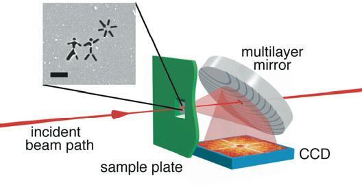
6 Structure Analysis
 DE z t At")
7 What is short in accelerators? 3GHz P in P out E(t) DE z t At 3GHz 1deg = 925fs


8 Short bunches by Magnetic Compression d DE/E z i chirp d d undercompression z z z z di V = V 0 sin(kz) Dz = R 56 d Accelerating Voltage Path-Length Energy- Dependent Beamline
9 Short bunches by Ballistic Compression Velocity Bunching By decelerating the bunch head and accelerating the bunch tail Accelerating Field E(t) Need one dedicated accelerating cavity No CSR effect and emittance dilution in the bends t Classical method with low energy thermoionic guns New concept with guns and emittance compensation
10 Short bunches around the world ILC 500fs CLIC 130fs XFEL 80fs LCLS 75fs
11 How do we measure short bunch length Define characteristics of beam instrumentation 1- Longitudinal Profile RMS or FWHM values More precise information on the beam characteristic 2- Single shot measurements 1 n! Sampling measurements Do not care about the beam reproducibility No additional problem due to timing jitter 3- Non interceptive Destructive Devices Can be used for beam study and beam control for on-line monitoring No risk of damage by the beam itself
12 How do we measure short bunches Level of Difficulty and Reliability Beam diagnostics should help you to understand how the beam behaves, it should not be the opposite A detector, what for? Online Beam stability Non-intercepting and reliable Only have access to a partial information (RMS values,..) Beam characterization and beam physics study Full information Complexity and time consuming
13 How do we measure short bunches Can we do non intercepting, single shot, beam profile measurement in an easy way? = All in red perfect system


14 How do we measure short bunches Optical Method Bunch Frequency 1. Produce visible light 2. Analyse the light pulse using dedicated instruments The shorter the bunches, the broader the bunch frequency spectrum cavities manipulation Use cavities to convert time information into spatial information -based beam diagnostic Using short laser pulses and sampling techniques

15 Cherenkov radiation Equivalent to the supersonic boom but for photons Threshold process: Particles go faster than light b > 1/n n is the index of refraction b is the relative particle velocity g is the particle relativistic factor g c is the Cherenkov light emission angle cos 1 b c 1 1 bn l the length of the cherenkov radiator 2 N cherenkov 1 2 l a 1 b 1 b 1 2 n 2 The total number of photons proportional to the thickness of the Cherenkov radiator more
 A huge amount of development for the past 30 years TR is generated when a charged particle passes through the interface between two materials with different")

16 Optical Transition Radiation Light intensity (arb.unit.) A huge amount of development for the past 30 years TR is generated when a charged particle passes through the interface between two materials with different permittivity (screen in vacuum) 4x10 4 3x10 4 Polarization Parallel I (, ) Perpendicular I ( = 0, ) OTR Backward emission 2x10 4 1x10 4 ~2/g Specular reflection N OTR Radiation wavelength ln ln2 1 b g 2 a Angle (rad) Number of OTR photons per charge particle ~ in [ ]nm Beam energy more Limitations : The thermal limit for best screens (C, Be, SiC) is ~ nc/cm 2 DT 2 r de N tot 2 2 ( r) e 2 dx 2 cp
 satisfies the condition : Beam energy h g 2 Radiation wavelength")
 104801 Limitations : Not enough photons in the visible for low energy particles : E")
17 Optical Diffraction Radiation DR is generated when a charged particle passes through an aperture or near an edge of dielectric materials, if the distance to the target h (impact parameter) satisfies the condition : Beam energy h g 2 Radiation wavelength Slit h e - ODR Light A lot of activities on ODR, but only one measurement up to now : T. Muto et al, Physical Review Letters 90 (2003) Limitations : Not enough photons in the visible for low energy particles : E < 1 GeV for a decent impact parameter (100mm)

18 Optical method : Streak Camera 1 Streak cameras uses a time dependent deflecting electric field to convert time information in spatial information on a CCD Mitsuru Uesaka et al, NIMA 406 (1998) fs time resolution obtained using reflective optics and 12.5nm bandwidth optical filter (800nm) and the Hamamatsu FESCA 200 Limitations : Time resolution of the streak camera : (i) Initial velocity distribution of photoelectrons : narrow bandwidth optical filter (ii) Spatial spread of the slit image: small slit width (iii) Dispersion in the optics


 Sweep speed of")
19 Streak camera examples 666 ps Observation of bunch train Sweep speed of 250ps/mm Measure of bunch length = 4.5ps (1.4 mm) Sweep speed of 10ps/mm = 8.9ps (2.7 mm)
20 Exercise You have just been hired to work on a 5MeV electron gun 4ps bunch length. Your first job is dedicated to the design of a bunch length monitor using Cherenkov radiation and a streak camera. As a reminder, Cherenkov light is emitted when a charge particle travels inside a transparent medium with a velocity higher than the speed of light in this medium. The Cherenkov photons are emitted all along the material thickness Speed of light inside the material : b is the relative particle velocity g is the particle relativistic factor : d the thickness of the Cherenkov radiator v g c n with n is the index of refraction of the material 1 1 b 2 Questions: What is the minimum index of refraction of the given material so that Cherenkov effect occurs? The condition to produce Cherenkov is that b is higher than 1/n. In our case for 5MeV electron, g 1 and corresponds to a b = n should be then higher than Assuming that you will use fused silica as a Cherenkov radiator (index of refraction is 1.46), How thick must be the crystal to keep the time resolution below 1ps? Since the photons travel at a speed lower than the electrons, and the time resolution will correspond to the time difference between photons and electrons in order to traverse the radiator. d In the present case in order to keep the time resolution better than 1ps, it corresponds to 660mm Dt n c 1 bc
21 Exercise You have been promoted and are now in charge of the bunch length measurement at the end of the Linac for electrons energy of 50GeV (4ps bunch length). Your boss specifically asks for a non destructive method and you are considering Optical Diffraction Radiation. ODR is a pure high relativistic phenomenon (contraction of length), where a charged particle emits radiation when it passes close to the edge of a dielectric medium. To produce ODR, there is a condition to fulfill between the distance from the edge to the beam (h), the beam energy (g) and the wavelength () of the radiation you like to produce. h g 2 Questions: What will be the required minimum distance from the edge of the slit to the beam in order to produce visible photons (550nm wavelength) Following the mentioned formula, the limit to produce 550nm photons corresponds to 8mm Is that distance looks reasonable, Would you think it can be used at lower beam energies Without emittance dilution, the beam size shrinks with the beam energy and 8mm is quite large with respect to the maximum transverse beam size (some 100mm) you will find at these beam energies. In principle, 1mm would be still good enough and it would correspond to 6.25GeV electrons.
22 Exercise You are responsible for the purchase of the streak camera and you should define what are the parameter of the streak camera to buy. You were told that you need a minimum of 2points per sigma in order to clearly measure a Gaussian bunch length. Question: Assuming that your MCP-CCD system is 1cm wide in vertical and have 500pixels, what will be the minimum sweep speed (in ps/mm) of the streak tube in order to measure the bunch length in your linac The spatial resolution of the MCP-CCD system corresponds to 1/500 = 20 mm per pixel. Your bunch length is 4ps sigma. Assuming that you need 2 pixels per sigma to measure the bunch length, you will need a sweep speed equivalent to 4ps/2pixels = 4ps/40mm = 100ps/mm The required sweep speed is 100ps/mm
23 Bunch Frequency For a given beam intensity, The shorter the bunch, the broader the bunch frequency spectrum Solid: Dash: Dash-dot: σ z = 1 ps σ z = 2 ps σ z = 3 ps Train of 5 and σ z = 2 ps The bandwidth of radiation produced from a Gaussian bunch, given by its Fourier transform, extends into the terahertz region for the ultra-short bunches 10 microns ~ 33.3femtoseconds ~ 30 THz From the measured frequency spectrum you can reconstructed the bunch length more
24 Bunch Frequency by Coherent Radiation When the wavelength of the radiation is longer than the bunch length, it is known that the coherent effect occurs inside the bunch For a given beam intensity, the shorter the bunch, the broader the bunch frequency spectrum The longitudinal shapes of the electron bunch can be extracted by analyzing the power spectrum of the radiation Intensity of coherent radiation N 2 Coherent Transition Radiation (CTR) P. Kung et al, Physical review Letters 73 (1994) 96 90fs, 32MeV beam Coherent Diffraction (CDR) B. Feng et al, NIM A 475 (2001) ; A.H. Lumpkin et al, NIM A 475 (2001) ; C. Castellano et al, Physical Review E 63 (2001) T. Watanabe et al, NIM A 437 (1999) 1-11 & NIM A 480 (2002) more 700fs, 35MeV beam 470fs, 150MeV beam


25 Bunch Frequency by Coherent Radiation n! Michelson or Martin-Pupplet interferometer : The radiation is split in two bunches, one is delayed by a linear stage and the intensity of the recombined bunch is measured by two detectors (one for each polarization) The spectrum is obtained from the Fourier transform of the interferometer function 1 The polychromator enables to get the spectrum directly by a single shot. The radiation is deflected by a grating and resolved by the xx-channelsdetector array Limitations : Narrow dynamic range limited by the small bandwidth sensitivity of the system element (Grating, Beam splitter, ) Need cross calibrations more Resolution depends on the number of detectors (polychromator)

26 Exercise You did so well for the bunch length measurement in the linac that you are asked to provide some support to operate of the bunch compressors. The bunch compression is done using an accelerating structure and a magnetic chicane. A coherent diffraction radiation monitor is measuring the bunch frequency spectrum just downstream of the chicane. Coherent radiation monitor relies on the fact that the shorter the bunch the broader the bunch frequency spectrum. Accelerating Field E(t) 2 1 t Questions: On the figure, there are two different settings of the klystron phase. For these two cases, draw what will be the trajectory of electrons sitting at the head and at the tail of the bunch for each case? On the CDR monitor, two different bunch frequency spectra have been measured. Choose which spectra corresponds to which phase settings Are you happy with the performance of the bunch compressor? if not what will you modify to have a better result


27 Exercise Questions: On the figure, there are two different settings of the klystron phase. For these two cases, draw what will be the trajectory of electrons sitting at the head and at the tail of the bunch for each case? Case 1 Case 2 On the CDR monitor, two different bunch frequency spectra have been measured. Choose which spectra corresponds to which phase settings In case 1, the beam head is accelerated more than the tail such that it experiences a short trajectory than the tail in the chicane. Therefore the bunch gets longer. In case 2, the beam head and tail have the same energy so they will also have the same trajectory, the bunch length will remain the same. On the CDR you will measure a broader spectrum for the shortest bunch, which will be with the present setting for case 2. Are you happy with the performance of the bunch compressor? if not what will you modify to have a better result The bunch compressor is stretching the bunch at the moment and you are not satisfied, you suggest then to change the phase of the klystron in order to bring the bunch on the negative slope of the. This will correspond to bunch compression, accelerating more the tail than the head of the bunch.
28 by Deflecting Cavity 1 The Deflector can be seen as a relativistic streak tube. The time varying deflecting field of the cavity transforms the time information into a spatial information The bunch length is then deduced measuring the beam size at a downstream position using a screen or (LWS) R. Akre et al, SLAC-PUB-8864, SLAC-PUB-9241, mm, 28GeV beam using a S-band deflector more Can extract even more information than the bunch length ex: slice emittance and intra bunch energy spread

29 by Deflecting Cavity more
30 Exercise With your new success, you really become an well recognized expert and the calibration of the deflector has been modified. You have been asked to calibrate the monitor. The deflector is working at 3GHz and for a maximum deflection (+/-90degree phase difference) the beam position on the screen changes by 5mm. Deflecting Field E(t) Zero - crossing y 2 y 0 2 z +90 t Questions: If the bunch is placed at the zero-crossing of the deflector. What happen to the beam position and to the beam size? The beam position remains unchanged but the beam size increases If the natural beam size (no ) on the screen is 10mm, what will be approximately the size increase for zero-crossing if the bunch is 1ps long. The relation between the bunch length the beam size on the screen with and without power is given by the following expression. 3 GHz frequency corresponds to 333ps time period. The period corresponds to 360degrees of phase variation such that 3GHz is equivalent to 83.25ps. The beam is moved by 5mm on the screen for a 90degrees klystron phase and would correspond to a time delay corresponding to 83.25ps 1ps is then equivalent to 60mm that will be added in quadrature to the 10mm of the original beam size. So the beam size will be then 60.8microns

31 Electro Optic Sampling n! This method is based on the polarization change of a laser beam which passes through a crystal itself polarized by the electrons electric field Bunch length is reconstructed by measuring the intensity of the polarization change as a function of laser timing A. M. MacLeod et al, Physical Review Letters 85 (2000) 3404 Using 12fs Ti:Al2O3 laser at 800nm and ZnTe crystal 0.5mm thick and a beam of 46MeV, 200pC, 2ps. more Limitations : Presence of phonon (5.3THz for ZnTe) can distort the measurement for bunch length < 200fs Radiation hardness (no problem observed up to now) Jitter of the laser- synchronization
32 Sampling Techniques more
33 Electro Optic based bunch length monitors 1. Sampling: multi-shot method arbitrary time window possible 2. Chirp laser method, spectral encoding): laser bandwidth limited~ 250fs I. Wilke et.al., PRL Vol.88, No Spatial encoding: imaging limitation ~ fs A. Cavalieri, et. al., PRL. 94, Temporal decoding: laser pulse length limited ~ 30fs S.P. Jamison, et.al., PRL Vol.93, No.11 more
34 How do we measure short bunches Optical radiation Cherenkov radiation X Optical Transition Radiation X Optical Diffraction Radiation X Streak camera X X > 200fs Coherent radiation Interferometry X X Polychromator X X Deflector X X X 1 n! Limitations Electro Optic Method Sampling X X X Jitter Spectral decoding X X X > 200fs Spatial decoding X X X > 50fs Temporal decoding X X X > 50fs
35 Exercise You are now working on the design of 4 th generation light source and you have been asked to define the several techniques to measure bunch length all along the machine. Choose at least one location where the following detector could be used along the machine. - ODR with a streak camera - deflector - Coherent diffraction radiation - EO spatial decoding 150MeV 2.8ps 250MeV 630fs 4.5GeV 75fs 20GeV
36 LCLS Machine Schematic Courtesy of P. Krejcik
Particle Beam Diagnostics
 Particle Beam Diagnostics Prof. Carsten P. Welsch Further Reading CAS Beam Diagnostics, Dourdan, France (2008) DITANET Beam Diagnostics Schools in 2009 and 2011 DITANET Topical Workshops Transverse Beam
Short Pulse, Low charge Operation of the LCLS. Josef Frisch for the LCLS Commissioning Team
 Short Pulse, Low charge Operation of the LCLS Josef Frisch for the LCLS Commissioning Team 1 Normal LCLS Parameters First Lasing in April 10, 2009 Beam to AMO experiment August 18 2009. Expect first user
EO single-shot temporal measurements of electron bunches
 EO single-shot temporal measurements of electron bunches and of terahertz CSR and FEL pulses. Steven Jamison, Giel Berden, Allan MacLeod Allan Gillespie, Dino Jaroszynski, Britta Redlich, Lex van der Meer
Hiromitsu TOMIZAWA XFEL Division /SPring-8
 TUPLB10 (Poster: TUPB080) Non-destructive Real-time Monitor to measure 3D- Bunch Charge Distribution with Arrival Timing to maximize 3D-overlapping for HHG-seeded EUV-FEL Hiromitsu TOMIZAWA XFEL Division
Generation and characterization of ultra-short electron and x-ray x pulses
 Generation and characterization of ultra-short electron and x-ray x pulses Zhirong Huang (SLAC) Compact XFEL workshop July 19-20, 2010, Shanghai, China Ultra-bright Promise of XFELs Ultra-fast LCLS Methods
Free-electron laser SACLA and its basic. Yuji Otake, on behalf of the members of XFEL R&D division RIKEN SPring-8 Center
 Free-electron laser SACLA and its basic Yuji Otake, on behalf of the members of XFEL R&D division RIKEN SPring-8 Center Light and Its Wavelength, Sizes of Material Virus Mosquito Protein Bacteria Atom
Linac Driven Free Electron Lasers (III)
") Linac Driven Free Electron Lasers (III) Massimo.Ferrario@lnf.infn.it SASE FEL Electron Beam Requirements: High Brightness B n ( ) 1+ K 2 2 " MIN r #$ % &B! B n 2 n K 2 minimum radiation wavelength energy
Linac Driven Free Electron Lasers (III) Massimo.Ferrario@lnf.infn.it SASE FEL Electron Beam Requirements: High Brightness B n ( ) 1+ K 2 2 " MIN r #$ % &B! B n 2 n K 2 minimum radiation wavelength energy
SPPS: The SLAC Linac Bunch Compressor and Its Relevance to LCLS
 LCLS Technical Advisory Committee December 10-11, 2001. SPPS: The SLAC Linac Bunch Compressor and Its Relevance to LCLS Patrick Krejcik LCLS Technical Advisory Committee Report 1: July 14-15, 1999 The
H. Maesaka*, H. Ego, T. Hara, A. Higashiya, S. Inoue, S. Matsubara, T. Ohshima, K. Tamasaku, H. Tanaka, T. Tanikawa, T. Togashi, K. Togawa, H.
 H. Maesaka*, H. Ego, T. Hara, A. Higashiya, S. Inoue, S. Matsubara, T. Ohshima, K. Tamasaku, H. Tanaka, T. Tanikawa, T. Togashi, K. Togawa, H. Tomizawa, M. Yabashi, K. Yanagida, T. Shintake and Y. Otake
Experimental Optimization of Electron Beams for Generating THz CTR and CDR with PITZ
 Experimental Optimization of Electron Beams for Generating THz CTR and CDR with PITZ Introduction Outline Optimization of Electron Beams Calculations of CTR/CDR Pulse Energy Summary & Outlook Prach Boonpornprasert
Jitter measurement by electro-optical sampling
 Jitter measurement by electro-optical sampling VUV-FEL at DESY - Armin Azima S. Duesterer, J. Feldhaus, H. Schlarb, H. Redlin, B. Steffen, DESY Hamburg K. Sengstock, Uni Hamburg Adrian Cavalieri, David
LOLA: Past, present and future operation
 LOLA: Past, present and future operation FLASH Seminar 1/2/29 Christopher Gerth, DESY 8/5/29 FLASH Seminar Christopher Gerth 1 Outline Past Present Future 8/5/29 FLASH Seminar Christopher Gerth 2 Past
FURTHER UNDERSTANDING THE LCLS INJECTOR EMITTANCE*
 Proceedings of FEL014, Basel, Switzerland FURTHER UNDERSTANDING THE LCLS INJECTOR EMITTANCE* F. Zhou, K. Bane, Y. Ding, Z. Huang, and H. Loos, SLAC, Menlo Park, CA 9405, USA Abstract Coherent optical transition
Opportunities and Challenges for X
 Opportunities and Challenges for X -ray Free Electron Lasers for X-ray Ultrafast Science J. Hastings Stanford Linear Accelerator Center June 22, 2004 European XFEL Laboratory How Short is short? defined
Femto-second FEL Generation with Very Low Charge at LCLS
 Femto-second FEL Generation with Very Low Charge at LCLS Yuantao Ding, For the LCLS commissioning team X-ray Science at the Femtosecond to Attosecond Frontier workshop May 18-20, 2009, UCLA SLAC-PUB-13525;
Time resolved transverse and longitudinal phase space measurements at the high brightness photo injector PITZ
 Time resolved transverse and longitudinal phase space measurements at the high brightness photo injector PITZ 1. Motivation 2. Transverse deflecting structure 3. Longitudinal phase space tomography 4.
Linac Based Photon Sources: XFELS. Coherence Properties. J. B. Hastings. Stanford Linear Accelerator Center
 Linac Based Photon Sources: XFELS Coherence Properties J. B. Hastings Stanford Linear Accelerator Center Coherent Synchrotron Radiation Coherent Synchrotron Radiation coherent power N 6 10 9 incoherent
Electro-optic techniques for temporal profile characterisation of relativistic Coulomb fields and Coherent Synchrotron Radiation.
 Electro-optic techniques for temporal profile characterisation of relativistic Coulomb fields and Coherent Synchrotron Radiation. S.. Jamison a,c, G. Berden b A.M. MacLeod a D.A. Jaroszynski c B. Redlich
Diagnostic Systems for Characterizing Electron Sources at the Photo Injector Test Facility at DESY, Zeuthen site
 1 Diagnostic Systems for Characterizing Electron Sources at the Photo Injector Test Facility at DESY, Zeuthen site Sakhorn Rimjaem (on behalf of the PITZ team) Motivation Photo Injector Test Facility at
Observation of Coherent Optical Transition Radiation in the LCLS Linac
 Observation of Coherent Optical Transition Radiation in the LCLS Linac Henrik Loos, Ron Akre, Franz-Josef Decker, Yuantao Ding, David Dowell, Paul Emma,, Sasha Gilevich, Gregory R. Hays, Philippe Hering,
INVESTIGATIONS OF THE DISTRIBUTION IN VERY SHORT ELECTRON BUNCHES LONGITUDINAL CHARGE
 INVESTIGATIONS OF THE LONGITUDINAL CHARGE DISTRIBUTION IN VERY SHORT ELECTRON BUNCHES Markus Hüning III. Physikalisches Institut RWTH Aachen IIIa and DESY Invited talk at the DIPAC 2001 Methods to obtain
Investigations on the electron bunch distribution in the longitudinal phase space at a laser driven RF-electron source for the European X-FEL
 Juliane Rönsch Universität Hamburg / DESY Investigations on the electron bunch distribution in the longitudinal phase space at a laser driven RF-electron source for the European X-FEL 5/27/2009 1 Contents
Present Capabilities and Future Concepts for Intense THz from SLAC Accelerators
 Present Capabilities and Future Concepts for Intense THz from SLAC Accelerators Alan Fisher SLAC National Accelerator Laboratory Frontiers of Terahertz Science SLAC 2012 September 6 1 THz from an Accelerated
Femtosecond X-ray Pulse Temporal Characterization in Free-Electron Lasers Using a Transverse Deflector. Abstract
 SLAC PUB 14534 September 2011 Femtosecond X-ray Pulse Temporal Characterization in Free-Electron Lasers Using a Transverse Deflector Y. Ding 1, C. Behrens 2, P. Emma 1, J. Frisch 1, Z. Huang 1, H. Loos
Diagnostic Systems for High Brightness Electron Injectors
 Diagnostic Systems for High Brightness Electron Injectors Henrik Loos 48 th ICFA Advanced Beam Dynamics Workshop on Future Light Sources SLAC 2010 1 1 Henrik Loos LCLS Injector Injector Diagnostics Characterize
SPARCLAB. Source For Plasma Accelerators and Radiation Compton with Laser And Beam
 SPARCLAB Source For Plasma Accelerators and Radiation Compton with Laser And Beam EMITTANCE X X X X X X X X Introduction to SPARC_LAB 2 BRIGHTNESS (electrons) B n 2I nx ny A m 2 rad 2 The current can be
Flexible control of femtosecond pulse duration and separation using an emittance-spoiling foil in x-ray free-electron lasers
 SLAC PUB 16312 June 2015 Flexible control of femtosecond pulse duration and separation using an emittance-spoiling foil in x-ray free-electron lasers Y. Ding 1, C. Behrens 2, R. Coffee 1, F.-J. Decker
CONCEPTUAL STUDY OF A SELF-SEEDING SCHEME AT FLASH2
 CONCEPTUAL STUDY OF A SELF-SEEDING SCHEME AT FLASH2 T. Plath, L. L. Lazzarino, Universität Hamburg, Hamburg, Germany K. E. Hacker, T.U. Dortmund, Dortmund, Germany Abstract We present a conceptual study
Low slice emittance preservation during bunch compression
 Low slice emittance preservation during bunch compression S. Bettoni M. Aiba, B. Beutner, M. Pedrozzi, E. Prat, S. Reiche, T. Schietinger Outline. Introduction. Experimental studies a. Measurement procedure
Juliane Rönsch Hamburg University. Investigations of the longitudinal phase space at a photo injector for the X-FEL
 Juliane Rönsch Hamburg University Investigations of the longitudinal phase space at a photo injector for the X-FEL Juliane Rönsch 1/15/28 1 Contents Introduction PITZ Longitudinal phase space of a photoinjector
Optimum beam creation in photoinjectors using spacecharge expansion II: experiment
 Optimum beam creation in photoinjectors using spacecharge expansion II: experiment J. Rosenzweig, A. Cook, M. Dunning, R.J. England, G. Travish, UCLA P. Musumeci, C. Vicario, D. Filippetto, M. Ferrario,
Coherent Cherenkov radiation from ultra-short electron bunch passing through vacuum channel in conical target
 Coherent Cherenkov radiation from ultra-short electron bunch passing through vacuum channel in conical target A.P. Potylitsyn, S.Yu. Gogolev RREPS_11, London, 2011, Sept.12-16 Motivation Existing experimental
Commissioning of the new Injector Laser System for the Short Pulse Project at FLASH
 Commissioning of the new Injector Laser System for the Short Pulse Project at FLASH Uni Hamburg tim.plath@desy.de 05.11.2013 Supported by BMBF under contract 05K10GU2 & FS FLASH 301 Motivation short pulses
FLASH overview. Nikola Stojanovic. PIDID collaboration meeting, Hamburg,
 FLASH overview Nikola Stojanovic PIDID collaboration meeting, Hamburg, 16.12.2011 Outline Overview of the FLASH facility Examples of research at FLASH Nikola Stojanovic PIDID: FLASH overview Hamburg, December
X-band Experience at FEL
 X-band Experience at FERMI@Elettra FEL Gerardo D Auria Elettra - Sincrotrone Trieste GdA_TIARA Workshop, Ångström Laboratory, June 17-19, 2013 1 Outline The FERMI@Elettra FEL project Machine layout and
An Adventure in Marrying Laser Arts and Accelerator Technologies
 An Adventure in Marrying Laser Arts and Accelerator Technologies Dao Xiang Beam Physics Dept, SLAC, Stanford University Feb-28-2012 An example sample Probe (electron) Pump (laser) Typical pump-probe experiment
LCLS Injector Prototyping at the GTF
 LCLS Injector Prototyping at at the GTF John John Schmerge, SLAC SLAC November 3, 3, 23 23 GTF GTF Description Summary of of Previous Measurements Longitudinal Emittance Transverse Emittance Active LCLS
STATUS OF E-157: METER-LONG PLASMA WAKEFIELD EXPERIMENT. Presented by Patrick Muggli for the E-157 SLAC/USC/LBNL/UCLA Collaboration
 STATUS OF E-157: METER-LONG PLASMA WAKEFIELD EXPERIMENT Presented by Patrick Muggli for the E-157 SLAC/USC/LBNL/UCLA Collaboration OUTLINE Basic E-157 Acelleration, Focusing Plasma Source Diagnostics:
ASTRA simulations of the slice longitudinal momentum spread along the beamline for PITZ
 ASTRA simulations of the slice longitudinal momentum spread along the beamline for PITZ Orlova Ksenia Lomonosov Moscow State University GSP-, Leninskie Gory, Moscow, 11999, Russian Federation Email: ks13orl@list.ru
Microbunching Workshop 2010 March 24, 2010, Frascati, Italy. Zhirong Huang
 Measurements of the LCLS Laser Heater and its impact on the LCLS FEL Performance Z. Huang for the LCLS commissioning team LCLS 1 1 Outline Introduction LCLS setup and measurements Effects on FEL performance
Overview on the longitudinal diagnostics for ERLs
 Overview on the longitudinal diagnostics for ERLs Holger Schlarb DESY 22607 Hamburg introduction injector & energy spread coherent radiation diagnostics and feedback ultra-short pulse diagnostics Prototype
BUNCH LENGTH MEASUREMENT AT THE FERMILAB A0 PHOTOINJECTOR USING A MARTIN-PUPLETT INTERFEROMETER *
 BUNCH LENGTH MEASUREMENT AT THE FERMILAB A0 PHOTOINJECTOR USING A MARTIN-PUPLETT INTERFEROMETER * Randy Thurman-Keup #, Raymond Patrick Fliller, Grigory Kazakevich (Fermilab, P.O. Box 500, Batavia, Illinois
RF-Gun Experience at PITZ - Longitudinal Phase Space
 - Collaboration meeting 9th of October 2006 Hamburg University Juliane Rönsch 1 Motivation special device to measure the longitudinal phase space at low momentum typical high energy diagnostics can not
SRF GUN CHARACTERIZATION - PHASE SPACE AND DARK CURRENT MEASUREMENTS AT ELBE*
 SRF GUN CHARACTERIZATION - PHASE SPACE AND DARK CURRENT MEASUREMENTS AT ELBE* E. Panofski #, A. Jankowiak, T. Kamps, Helmholtz-Zentrum Berlin, Berlin, Germany P.N. Lu, J. Teichert, Helmholtz-Zentrum Dresden-Rossendorf,
X-Band RF Harmonic Compensation for Linear Bunch Compression in the LCLS
 SLAC-TN-5- LCLS-TN-1-1 November 1,1 X-Band RF Harmonic Compensation for Linear Bunch Compression in the LCLS Paul Emma SLAC November 1, 1 ABSTRACT An X-band th harmonic RF section is used to linearize
SPARCLAB. Source For Plasma Accelerators and Radiation Compton. On behalf of SPARCLAB collaboration
 SPARCLAB Source For Plasma Accelerators and Radiation Compton with Laser And Beam On behalf of SPARCLAB collaboration EMITTANCE X X X X X X X X 2 BRIGHTNESS (electrons) B n 2I nx ny A m 2 rad 2 The current
Femto second X ray Pulse Generation by Electron Beam Slicing. F. Willeke, L.H. Yu, NSLSII, BNL, Upton, NY 11973, USA
 Femto second X ray Pulse Generation by Electron Beam Slicing F. Willeke, L.H. Yu, NSLSII, BNL, Upton, NY 11973, USA r 2 r 1 y d x z v Basic Idea: When short electron bunch from linac (5MeV, 50pC,100fs)
Simulations of the IR/THz Options at PITZ (High-gain FEL and CTR)
") Case Study of IR/THz source for Pump-Probe Experiment at the European XFEL Simulations of the IR/THz Options at PITZ (High-gain FEL and CTR) Introduction Outline Simulations of High-gain FEL (SASE) Simulation
Case Study of IR/THz source for Pump-Probe Experiment at the European XFEL Simulations of the IR/THz Options at PITZ (High-gain FEL and CTR) Introduction Outline Simulations of High-gain FEL (SASE) Simulation
X-ray Free-electron Lasers
 X-ray Free-electron Lasers Ultra-fast Dynamic Imaging of Matter II Ischia, Italy, 4/30-5/3/ 2009 Claudio Pellegrini UCLA Department of Physics and Astronomy Outline 1. Present status of X-ray free-electron
VELA/CLARA as Advanced Accelerator Studies Test-bed at Daresbury Lab.
 VELA/CLARA as Advanced Accelerator Studies Test-bed at Daresbury Lab. Yuri Saveliev on behalf of VELA and CLARA teams STFC, ASTeC, Cockcroft Institute Daresbury Lab., UK Outline VELA (Versatile Electron
LCLS Accelerator Parameters and Tolerances for Low Charge Operations
 LCLS-TN-99-3 May 3, 1999 LCLS Accelerator Parameters and Tolerances for Low Charge Operations P. Emma SLAC 1 Introduction An option to control the X-ray FEL output power of the LCLS [1] by reducing the
Coherent THz Pulses: Source and Science at the NSLS
 Coherent THz Pulses: Source and Science at the NSLS H. Loos, B. Sheehy, D. Arena, J.B. Murphy, X.-J. Wang and G. L. Carr Brookhaven National Laboratory carr@bnl.gov http://www.nsls.bnl.gov http://infrared.nsls.bnl.gov
Electro optic sampling as a timing diagnostic at Pegasus lab
 Electro optic sampling as a timing diagnostic at Pegasus lab Cheyne M. Scoby Particle Beam Physics Lab, UCLA 13 January 2009 High Power High Brightness Workshop Los Angeles, CA Outline Motivation for EOS
Femtosecond Width X-ray Generation with the SLAC Linac and the FFTB Beamline *
 SLAC-PUB-8858 June 1 Femtosecond Width X-ray Generation with the SLAC Linac and the FFTB Beamline * P. Krejcik, J. Arthur, R. Carr, M. Cornacchia, P. Emma, R. Iverson, J. Safranek, R. Tatchyn. Stanford
S2E (Start-to-End) Simulations for PAL-FEL. Eun-San Kim
 Simulations for PAL-FEL. Eun-San Kim") S2E (Start-to-End) Simulations for PAL-FEL Aug. 25 2008 Kyungpook Nat l Univ. Eun-San Kim 1 Contents I Lattice and layout for a 10 GeV linac II Beam parameters and distributions III Pulse-to-pulse stability
S2E (Start-to-End) Simulations for PAL-FEL Aug. 25 2008 Kyungpook Nat l Univ. Eun-San Kim 1 Contents I Lattice and layout for a 10 GeV linac II Beam parameters and distributions III Pulse-to-pulse stability
II) Experimental Design
 Experimental Design") SLAC Experimental Advisory Committee --- September 12 th, 1997 II) Experimental Design Theory and simulations Great promise of significant scientific and technological achievements! How to realize this
SLAC Experimental Advisory Committee --- September 12 th, 1997 II) Experimental Design Theory and simulations Great promise of significant scientific and technological achievements! How to realize this
THz Electron Gun Development. Emilio Nanni 3/30/2016
 THz Electron Gun Development Emilio Nanni 3/30/2016 Outline Motivation Experimental Demonstration of THz Acceleration THz Generation Accelerating Structure and Results Moving Forward Parametric THz Amplifiers
PoS(EPS-HEP2017)533. First Physics Results of AWAKE, a Plasma Wakefield Acceleration Experiment at CERN. Patric Muggli, Allen Caldwell
533. First Physics Results of AWAKE, a Plasma Wakefield Acceleration Experiment at CERN. Patric Muggli, Allen Caldwell") First Physics Results of AWAKE, a Plasma Wakefield Acceleration Experiment at CERN Patric Muggli, Max Planck Institute for Physics E-mail: muggli@mpp.mpg.de AWAKE is a plasma wakefield acceleration experiment
First Physics Results of AWAKE, a Plasma Wakefield Acceleration Experiment at CERN Patric Muggli, Max Planck Institute for Physics E-mail: muggli@mpp.mpg.de AWAKE is a plasma wakefield acceleration experiment
X-band RF driven hard X-ray FELs. Yipeng Sun ICFA Workshop on Future Light Sources March 5-9, 2012
 X-band RF driven hard X-ray FELs Yipeng Sun ICFA Workshop on Future Light Sources March 5-9, 2012 Motivations & Contents Motivations Develop more compact (hopefully cheaper) FEL drivers, L S C X-band (successful
Beam compression experiments using the UCLA/ATF compressor
 Beam compression experiments using the UCLA/ATF compressor J.B. ROSENZWEIG, M. DUNNING, E. HEMSING, G. ANDONIAN, A.M. COOK, A. MUROKH, S. REICHE, D. SCHILLER, M. BABZIEN #, K. KUSCHE #, V. YAKIMENKO #,
Longitudinal Measurements at the SLAC Gun Test Facility*
 SLAC-PUB-9541 September Longitudinal Measurements at the SLAC Gun Test Facility* D. H. Dowell, P. R. Bolton, J.E. Clendenin, P. Emma, S.M. Gierman, C.G. Limborg, B.F. Murphy, J.F. Schmerge Stanford Linear
UCLA Neptune Ramped Bunch Experiment. R. Joel England UCLA Department of Physics and Astronomy Particle Beam Physics Laboratory May 19, 2004
 UCLA Neptune Ramped Bunch Experiment R. Joel England UCLA Department of Physics and Astronomy Particle Beam Physics Laboratory May 19, 2004 Outline 1. Background & Motivation 2. Neptune Dogleg Compressor
Plasma-based Acceleration at SLAC
 Plasmabased Acceleration at SLAC Patric Muggli University of Southern California muggli@usc.edu for the E167 collaboration E167 Collaboration: I. Blumenfeld, F.J. Decker, P. Emma, M. J. Hogan, R. Iverson,
Excitements and Challenges for Future Light Sources Based on X-Ray FELs
 Excitements and Challenges for Future Light Sources Based on X-Ray FELs 26th ADVANCED ICFA BEAM DYNAMICS WORKSHOP ON NANOMETRE-SIZE COLLIDING BEAMS Kwang-Je Kim Argonne National Laboratory and The University
Beam Echo Effect for Generation of Short Wavelength Radiation
 Beam Echo Effect for Generation of Short Wavelength Radiation G. Stupakov SLAC NAL, Stanford, CA 94309 31st International FEL Conference 2009 Liverpool, UK, August 23-28, 2009 1/31 Outline of the talk
FACET-II Design Update
 FACET-II Design Update October 17-19, 2016, SLAC National Accelerator Laboratory Glen White FACET-II CD-2/3A Director s Review, August 9, 2016 Planning for FACET-II as a Community Resource FACET-II Photo
Echo-Enabled Harmonic Generation
 Echo-Enabled Harmonic Generation G. Stupakov SLAC NAL, Stanford, CA 94309 IPAC 10, Kyoto, Japan, May 23-28, 2010 1/29 Outline of the talk Generation of microbunching in the beam using the echo effect mechanism
Dielectric Accelerators at CLARA. G. Burt, Lancaster University On behalf of ASTeC, Lancaster U., Liverpool U., U. Manchester, and Oxford U.
 Dielectric Accelerators at CLARA G. Burt, Lancaster University On behalf of ASTeC, Lancaster U., Liverpool U., U. Manchester, and Oxford U. Dielectric Accelerators Types Photonic structures Dielectric
Fast Simulation of FEL Linacs with Collective Effects. M. Dohlus FLS 2018
 Fast Simulation of FEL Linacs with Collective Effects M. Dohlus FLS 2018 A typical X-FEL gun environment photo cathode cavity, solenoid, drift straight cavity, quadrupole, drift dispersive bend, quadrupole,
ATTOSECOND X-RAY PULSES IN THE LCLS USING THE SLOTTED FOIL METHOD
 P. Emma et al. / Proceedings of the 24 FEL Conference, 333-338 333 ATTOSECOND X-RAY PULSES IN THE LCLS USING THE SLOTTED FOIL METHOD Abstract P. Emma, Z. Huang, SLAC, Stanford, CA 9439, USA M. Borland,
Femtosecond and sub-femtosecond x-ray pulses from a SASE-based free-electron laser. Abstract
 SLAC-PUB-12 Femtosecond and sub-femtosecond x-ray pulses from a SASE-based free-electron laser P. Emma, K. Bane, M. Cornacchia, Z. Huang, H. Schlarb, G. Stupakov, and D. Walz Stanford Linear Accelerator
Parameter selection and longitudinal phase space simulation for a single stage X-band FEL driver at 250 MeV
 Parameter selection and longitudinal phase space simulation for a single stage X-band FEL driver at 25 MeV Yipeng Sun and Tor Raubenheimer, Juhao Wu SLAC, Stanford, CA 9425, USA Hard x-ray Free electron
Longitudinal phase space tomography and its. implementation in energy recovery linacs
 SLAC PUB 11755 Longitudinal phase space tomography and its implementation in energy recovery linacs H. Loos SLAC, 2575 Sand Hill Road, Menlo Park, CA 9425, USA Abstract Applying tomographic techniques
Excitements and Challenges for Future Light Sources Based on X-Ray FELs
 Excitements and Challenges for Future Light Sources Based on X-Ray FELs 26th ADVANCED ICFA BEAM DYNAMICS WORKSHOP ON NANOMETRE-SIZE COLLIDING BEAMS Kwang-Je Kim Argonne National Laboratory and The University
3. Synchrotrons. Synchrotron Basics
 1 3. Synchrotrons Synchrotron Basics What you will learn about 2 Overview of a Synchrotron Source Losing & Replenishing Electrons Storage Ring and Magnetic Lattice Synchrotron Radiation Flux, Brilliance
X-Ray Diagnostics Commissioning at the LCLS
 X-Ray Diagnostics Commissioning at the LCLS - Selected Studies - J. Welch, SLAC National Accelerator Laboratory Aug. 3-27, 2010 Commissioning Studies Microbunching Instability Laser Heater tune-up Gas
Brightness and Coherence of Synchrotron Radiation and Free Electron Lasers. Zhirong Huang SLAC, Stanford University May 13, 2013
 Brightness and Coherence of Synchrotron Radiation and Free Electron Lasers Zhirong Huang SLAC, Stanford University May 13, 2013 Introduction GE synchrotron (1946) opened a new era of accelerator-based
Measurement of wakefields in hollow plasma channels Carl A. Lindstrøm (University of Oslo)
") Measurement of wakefields in hollow plasma channels Carl A. Lindstrøm (University of Oslo) in collaboration with Spencer Gessner (CERN) presented by Erik Adli (University of Oslo) FACET-II Science Workshop
Measurement of wakefields in hollow plasma channels Carl A. Lindstrøm (University of Oslo) in collaboration with Spencer Gessner (CERN) presented by Erik Adli (University of Oslo) FACET-II Science Workshop
Simulations of the IR/THz source at PITZ (SASE FEL and CTR)
") Simulations of the IR/THz source at PITZ (SASE FEL and CTR) Introduction Outline Simulations of SASE FEL Simulations of CTR Summary Issues for Discussion Mini-Workshop on THz Option at PITZ DESY, Zeuthen
Simulations of the IR/THz source at PITZ (SASE FEL and CTR) Introduction Outline Simulations of SASE FEL Simulations of CTR Summary Issues for Discussion Mini-Workshop on THz Option at PITZ DESY, Zeuthen
1 Mathematical description of ultrashort laser pulses
 1 Mathematical description of ultrashort laser pulses 1.1 We first perform the Fourier transform directly on the Gaussian electric field: E(ω) = F[E(t)] = A 0 e 4 ln ( t T FWHM ) e i(ω 0t+ϕ CE ) e iωt
What have we learned from the LCLS injector?*
 SLAC-PUB-14644 LCLS-TN-11-4 October 19, 2011 What have we learned from the LCLS injector?* Feng Zhou and Axel Brachmann for the LCLS injector team The LCLS injector reliably delivered a high quality electron
PAL LINAC UPGRADE FOR A 1-3 Å XFEL
 PAL LINAC UPGRADE FOR A 1-3 Å XFEL J. S. Oh, W. Namkung, Pohang Accelerator Laboratory, POSTECH, Pohang 790-784, Korea Y. Kim, Deutsches Elektronen-Synchrotron DESY, D-603 Hamburg, Germany Abstract With
R&D experiments at BNL to address the associated issues in the Cascading HGHG scheme
 R&D experiments at BNL to address the associated issues in the Cascading HGHG scheme Li Hua Yu for DUV-FEL Team National Synchrotron Light Source Brookhaven National Laboratory FEL2004 Outline The DUVFEL
Emittance and Quantum Efficiency Measurements from a 1.6 cell S- Band Photocathode RF Gun with Mg Cathode *
 LCLS-TN-4-3 SLAC PUB 763 September, 4 Emittance and Quantum Efficiency Measurements from a.6 cell S- Band Photocathode RF Gun with Mg Cathode * J.F. Schmerge, J.M. Castro, J.E. Clendenin, D.H. Dowell,
Supplementary Figure 1 Schematics of an optical pulse in a nonlinear medium. A Gaussian optical pulse propagates along z-axis in a nonlinear medium
 Supplementary Figure 1 Schematics of an optical pulse in a nonlinear medium. A Gaussian optical pulse propagates along z-axis in a nonlinear medium with thickness L. Supplementary Figure Measurement of
Insertion Devices Lecture 2 Wigglers and Undulators. Jim Clarke ASTeC Daresbury Laboratory
 Insertion Devices Lecture 2 Wigglers and Undulators Jim Clarke ASTeC Daresbury Laboratory Summary from Lecture #1 Synchrotron Radiation is emitted by accelerated charged particles The combination of Lorentz
SwissFEL INJECTOR DESIGN: AN AUTOMATIC PROCEDURE
 Proceedings of FEL03, New York, NY, USA SwissFEL INJECTOR DESIGN: AN AUTOMATIC PROCEDURE S. Bettoni, M. Pedrozzi, S. Reiche, PSI, Villigen, Switzerland Abstract The first section of FEL injectors driven
Short Introduction to CLIC and CTF3, Technologies for Future Linear Colliders
 Short Introduction to CLIC and CTF3, Technologies for Future Linear Colliders Explanation of the Basic Principles and Goals Visit to the CTF3 Installation Roger Ruber Collider History p p hadron collider
High Brilliance Beam Diagnostic
 High Brilliance Beam Diagnostic A. Cianchi Universityof it Rome Tor Vergata and INFN Outline Brightness and Brilliance Fundamental parameters Transverse and longitudinal measurements Intercepting and non
FLASH/DESY, Hamburg. Jörg Rossbach University of Hamburg & DESY, Germany - For the FLASH Team -
 First Lasing below 7nm Wavelength at FLASH/DESY, Hamburg Jörg Rossbach University of Hamburg & DESY, Germany - For the FLASH Team - email: joerg.rossbach@desy.de FLASH: The first FEL user facility for
Short Wavelength SASE FELs: Experiments vs. Theory. Jörg Rossbach University of Hamburg & DESY
 Short Wavelength SASE FELs: Experiments vs. Theory Jörg Rossbach University of Hamburg & DESY Contents INPUT (electrons) OUTPUT (photons) Momentum Momentum spread/chirp Slice emittance/ phase space distribution
Simulations of the Microbunching Instability in FEL Beam Delivery Systems
 Simulations of the Microbunching Instability in FEL Beam Delivery Systems Ilya Pogorelov Tech-X Corporation Workshop on High Average Power & High Brightness Beams UCLA, January 2009 Outline The setting:
Measurements of Short Bunches at SPPS and E-164X
 Measurements of Short Bunches at SPPS and E-164X P. Muggli (USC) M.J. Hogan, C.D. Barnes, D. Walz, R. Siemann P.J. Emma, P. Krejcik (SLAC) H. Schlarb, R. Ischebeck (DESY) P. Muggli, XFEL 24, SLAC 7/29/4
Low energy high brilliance beam characterization
 Low energy high brilliance beam characterization J. Bähr, DESY, Zeuthen, Germany Abstract Low energy high brilliance beam characterization plays an important role for electron sources and injectors of
O rion. The ORION Facility at SLAC. Bob Siemann AAC Workshop, June 15, 2000
 The ORION Facility at SLAC Bob Siemann AAC Workshop, June 15, 2000 1. Introduction 2. The ORION Workshop 3. What s Next? 4. Concluding Remarks http://www-project.slac.stanford.edu/orion/ Introduction Advanced
Experimental Path to Echo-75 at NLCTA
 Experimental Path to Echo-75 at NLCTA Erik Hemsing on behalf of the ECHO group at SLAC NLCTA ICFA Workshop on Future Light Sources March 5-9, 2012 Thomas Jefferson National Accelerator Facility Motivation
Two-Stage Chirped-Beam SASE-FEL for High Power Femtosecond X-Ray Pulse Generation
 Two-Stage Chirped-Beam SASE-FEL for High ower Femtosecond X-Ray ulse Generation C. Schroeder*, J. Arthur^,. Emma^, S. Reiche*, and C. ellegrini* ^ Stanford Linear Accelerator Center * UCLA 12-10-2001 LCLS-TAC
Advanced laser technology for 3D-shaping ~ toward to the highest brightness of electron beam source ~
 Advanced laser technology for 3D-shaping ~ toward to the highest brightness of electron beam source ~ Hiromistu Tomizawa Accelerator Division, Japan Synchrotron Radiation Research Institute (SPring-8)
Tuning Techniques And Operator Diagnostics for FACET at SLAC National Accelerator Laboratory. Chris Melton SLAC Accelerator Operations
 Tuning Techniques And Operator Diagnostics for FACET at SLAC National Accelerator Laboratory Chris Melton SLAC Accelerator Operations FACET Tuning And Diagnostics What is FACET? FACET Performance Challenges
L. Bobb 1, 2, M. Billing 3, N. Chritin 2, P. Karataev 1, T. Lefevre 2
 L. Bobb 1, 2, M. Billing 3, N. Chritin 2, P. Karataev 1, T. Lefevre 2 1. John Adams Institute at Royal Holloway, Egham, Surrey, United Kingdom 2. CERN European Organisation for Nuclear Research, CERN,