6593 Riverdale St. San Diego, CA (619) Page of
|
|
|
- Harriet Craig
- 5 years ago
- Views:
Transcription
1
2
3
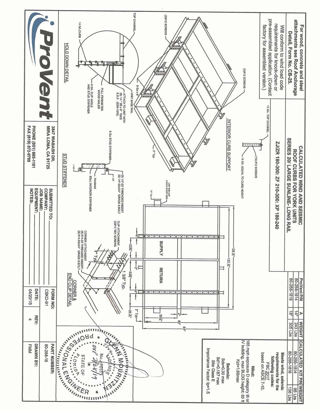
4 6593 Riverdale St. Client: ProVent PV1807 Description: CBKD-91 ( **) Unit: YORK ZJ,ZR / ZF / XP Curb Information Hcurb = 18 in (Height of curb) Lcurb = in (Length of curb) wcurb = 84 in (Width of curb) WGTcurb = 441 lbs (Weight of curb) Unit Information WGTunit = 2006 lbs (Weight of Unit) Wtmax = 534 lbs (Maximum corner weight) Wtmin = 470 lbs (Minimum corner weight) Hunit = in (Height of unit above curb) Hcm = in (Height to center of mass) Lunit = in (Length of unit) Wunit = 92 in (Width of unit) Seismic Loading FBC/2015 IBC Ss = 0.15 (Worst Case for state of Florida) Fa = 2.5 (Worst case Site class E from Table ASCE 7-10) Sms = (Fa*Ss) Sds = (2/3*Sms) Ip = 1.5 (Importance Factor Category III or IV Building) Fpmax = WGTunit (1.6*Sds*Ip)*WGTunit FpmaxASD = 843 lbs (0.7*Fpmax) FpmaxASD = 1028 lbs (unit only) (unit and curb) Wind Loading FBC/2015 IBC *** Exposure Category D *** Kz = 1.31 (For 60 ft roof height, Exposure D - Table ACSE 7-10) Kzt = 1.66 (Max. assumed topographic factor) Kd = 0.85 (Directionality factor Table ASCE 7-10) V = 190 (Wind velocity, mph for Occupancy Cat III-IV bldgs Exp. Cat D) GCr (horiz) = 1.9 (Refer Sect ASCE 7-10) GCr (vert) = 1.5 (Refer Sect ASCE 7-10) qz psf = *Kz*Kzt*Kd*V 2 (Eq ASCE 7-10) F h ASD trans = lbs = 0.6*qz*GCr*Lunit*(Hunit+Hcurb) (Eq ) F h ASD long = 8787 lbs = 0.6*qz*GCr*Wunit*(Hunit+Hcurb) F vert ASD = lbs = 0.6*qz*GCr*Lunit*Wunit (Eq ) Curb Loading Transverse: Compression SEISMIC = 1369 lbs =[FpmaxASD*Hcm+2*(1+0.14S DS )*Wtmax*wcurb]/wcurb Tension SEISMIC = 236 lbs = Comp SEISMIC -( S DS )*WGTunit Compression WIND = lbs =[F h transasd *Hcm+2*0.6*Wtmax*wcurb-F vertasd *wcurb/2]/wcurb Tension WIND = lbs = Comp WIND +Fvert-0.6*WGTunit ---> Negative values indicate Compression load rather than Tension Longitudinal: Compression SEISMIC = 1281 lbs =[FpmaxASD*Hcm+2*(1+0.14*S DS )*Wtmax*Lcurb]/Lcurb Tension SEISMIC = 148 lbs = Comp SEISMIC -( S DS )*WGTunit Compression WIND = lbs =[F h transasd *Hcm+2*0.6*Wtmax*Lcurb-F vertasd *Lcurb/2]/Lcurb Tension WIND = lbs = Comp WIND +Fvert-0.6*WGTunit ---> Negative values indicate Compression load rather than Tension Governing Reactions: Transverse: Comp MAX = 1369 lbs > Along long edge of curb. (on long edge) Tens MAX = lbs > Along long edge of curb. Longitudinal: Comp MAX = 1281 lbs > Along short edge of curb. (on short edge) Tens MAX = lbs > Along short edge of curb. ---> Negative values indicate Compression load rather than Tension
5 6593 Riverdale St. Curb Design Fy = 50 ksi Fu = 65 ksi t = Gauge E = ksi Calculate Section Properties of Curb A'= in a = in = A'-(2r+t) B'= in a'= in = A'-t C'= in (0 if no lips) b = in = B'-[r+t/2+α(r+t/2)] α = (0 - no Lip; 1 w/ lip) b'= in = B'-(t/2+αt/2) R = (Inside bend radius) c = in = α[c'-(r+t/2)] t = in c'= in = α(c'-t/2) r'= in = R+t/2 u = in = πr/2 x = in (Distance between centroid and web centerline) Ix = in (Moment of Inertia about X-Axis) Iy = in (Moment of Inertia about Y-Axis) A = 1.82 in 2 rx = 6.48 in ry = in rmin = in Axial Compression Pu = k (Max Axial Comp) Ωc = 1.80 Pn/Ωc = k λ Fe = ksi 1.5; λ λc = 0.89 Ω λ 1.5; Ω Fn = ksi λ Ly = 84 in Lateral unbraced length k y L y /r y = 68 (assume k=0.8) Compression Check = O.K. Check Web Crippling h = 18 in -- Check limits: C = 4.00 t = in h/t = C R = 0.14 N = 7.00 N/t = C N = 0.35 Ω w = 1.75 N/h = C h = 0.02 P n = k R/t = P n /Ω w = k sin 90 1 Long side: Pu Trans = k O.K. # clips = 3 Short side: Pu Long = k O.K. # clips = 2 ***h/t > 200; use web stiffeners Check Web Stiffener 16Ga x 3/4" x 7" (C-channel) width of stiffener = in ts = Gauge web of stiff. w = in Rs = in ***Check w/ts 1.28 E/Fys Ωc = 1.70 w/ts = (E/Fys) = > w/ts over limit Use C Pwc = k Ae = in 2 Pn = k Pn/Ω = k O.K. (See table C , fastened to support, one flange, end loading) 1 1 Corner Connections 1/4" φ SAE Grade 8 bolts w/ 1/4-20-UNC Threaded inserts Tcrnmax = 4312 lbs Max(F pmaxasd /4 -OR- Fh ASDtrans /4 corner connections) Vcrnmax = 6855 lbs (Max Ten/2 corner connections per side) Bolt: Tall = 2480 lbs Vall = 1096 lbs Threaded Insert: Tall = 2860 lbs Vall = 1714 lbs # of Bolts required for Tension = 1.7 # of Bolts required for Shear = 6.3 ***If combined fails: # of Bolts Used = 7.0 USE --> 8.0 Check Combined Stress in Bolts & Inserts: N.G. StressComb = O.K. Check 1/8" welded connection <--- USE WELD Ω = 2.35 Assume L/t > 25: 25*t = in Lreq'd = in Ω 1 Ω 0.75 Ω 0.75
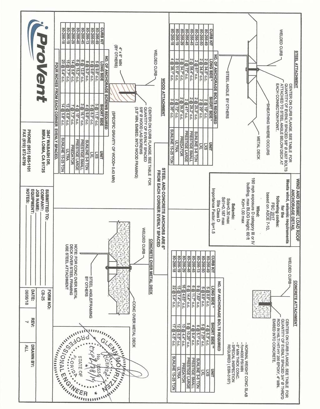
6 6593 Riverdale St. Connection Unit to Curb Clip #14 SMS screw Ω = 3.0 t1 = in Fu1 = 65 ksi t2 = in (unit base rail thickness) Fu2 = 65 ksi d = in (screw diameter) dw = in (nom. washer diameter) t2/t1 = 1.4 For t2/t1 1.0: Pns = 3028 # For t2/t1 2.5: : k Pns = 3028 # k k k k Pns/Ω = 1009 # <- Controls Pss/Ω = 1045 # 0.85 : Pnot = k (screw pull-out strength) min, Pnov = k (screw pull-over strength) 1.5 Pts/Ω = 453 # <- Controls Pts/Ω = 1220 # (full tensile screw capacity) Shear (k) # clips V clip (k) V allow (lb) # screws spacing Long side: # in Short side: # in clip width (in) = 7.00 clip height = 2.5 in min spacing = 0.73 in edge distance = 0.5 in (min. 1.5d) Check Block shear rupture: O.K. thinnest part = AISI BSR applies Fy = 50 ksi Ω = 2.22 bolt/screw connection Agv = in 2 Anv = in 2 Ant = in 2 Rn/Ω = k BSR O.K (AISI Sect. E5.3) Connection of Curb to Supporting Structure Roof Loading SEISMIC: ( SDS)D + 0.7E WIND: 0.6D + W Transverse: Uplift MAX = lbs Shear MAX = 8624 lbs Compression SEISMIC = 1808 lbs =[FpmaxASD*(Hcm+Hcurb)+(1+0.14S DS )*(WGT unit+curb /2)*wcurb]/wcurb Tension SEISMIC = 426 lbs =Comp SEISMIC -( S DS )*(WGTunit+curb) Compression WIND = 964 lbs =[F h transasd *(Hcm+Hcurb)+0.6*(WGT unit+curb /2)*wcurb-F vertasd *wcurb/2]/wcurb Tension WIND = lbs =[F h transasd *(Hcm+Hcurb)-0.6*(WGT unit+curb /2)*wcurb+F vertasd *wcurb/2]/wcurb Longitudinal: Uplift MAX = lbs Shear MAX = 4393 lbs Compression SEISMIC = 1627 lbs =[FpmaxASD*(Hcm+Hcurb)+(1+0.14S DS )*(WGT unit+curb /2)*Lcurb]/Lcurb Tension SEISMIC = 244 lbs =Comp SEISMIC -( S DS )*(WGTunit+curb) Compression WIND = lbs =[F h transasd *(Hcm+Hcurb)+0.6*(WGT unit+curb /2)*Lcurb-F vertasd *Lcurb/2]/Lcurb Tension WIND = lbs =[F h transasd *(Hcm+Hcurb)-0.6*(WGT unit+curb /2)*Lcurb+F vertasd *Lcurb/2]/Lcurb Wood Attachment: Use 5/8" φ wood lag screws w/ 3.5" Min. Embed Tall metal = lbs Vall metal = lbs Transverse: Tall wood = lbs Vall wood = 1024 lbs # of Screws Req'd for Uplift = COMBINED LOADING: O.K. # of Screws Req'd for Shear = 8.42 Screw Spacing = 5.4 in o.c. Total # of screws Required = 23 Use 5/8" φ wood lag 5.4 in o.c. along long side of curb w/ 3.5" Min. Embed Longitudinal: # of Screws Req'd for Uplift = 11.9 COMBINED LOADING: O.K. # of Screws Req'd for Shear = 4.3 Screw Spacing = 5.8 in o.c. Total # of screws Required = 14 Use 5/8" φ wood lag 5.8 in o.c. along short side of curb w/ 3.5" Min. Embed Steel Deck Attachment: Use 5/8" φ A307 Bolts attached to steel angle below deck Tall bolt = 6903 lbs Vall bolt = 3682 lbs Transverse: 6903 lbs 3682 lbs # of Bolts Req'd for Uplift = 2.50 COMBINED LOADING: O.K. # of Bolts Req'd for Shear = 2.34 Bolt Spacing = 38.1 in o.c. Total # of Bolts Required = 4 Use 5/8" φ A307 Bolts attached to steel angle below 38.1 in o.c. along long side of curb Longitudinal: # of Bolts Req'd for Uplift = 1.63 COMBINED LOADING: O.K. # of Bolts Req'd for Shear = 1.19 Req'd Min Spacing = 36.0 in o.c. Total # of Bolts Required = 3 Use 5/8" φ A307 Bolts attached to steel angle below 36 in o.c. along short side of curb
7 For Concrete anchorage: SEISMIC ( SDS)D + 0.7Ω o E (Ω o = 2.5) Concrete Attachment: 3/4" φ Hilti Hit-HY 200 adhesive anchors w/ 4" embed Tall LRFD = 1722 lbs Vall LRFD = 2032 lbs Tall ASD = Tall LRFD /α = lbs Vall ASD = Vall LRFD /α = lbs 0.465,0.535 Transverse: Uplift MAX = lbs Shear MAX = 8624 lbs Compression SEISMIC = 2622 lbs =[2.5*FpmaxASD*(Hcm+Hcurb)+(1+0.14S DS )*(WGT unit+curb /2)*wcurb]/wcurb Tension SEISMIC = 1239 lbs =Comp SEISMIC -( S DS )*(WGTunit+curb) Shear SEISMIC = 1285 lbs =2.5*FpmaxASD/2 Min Bolts Req'd Uplift = spacing = 5.68 in o.c. Tapplied = lbs Min Bolts Req'd Shear = 7.94 spacing = in o.c. Vapplied = lbs Try using 22 bolts COMBINED LOADING = 1.2 spaced at 5.44 in o.c.,, = 1.21 Use 22 3/4" φ Hilti Hit HY 200 adhesive 5.4 in o.c. max. along long side of curb w/ 4" embed Longitudinal: Uplift MAX = lbs Shear MAX = 8624 lbs Compression SEISMIC = 2168 lbs =[2.5*FpmaxASD*(Hcm+Hcurb)+(1+0.14S DS )*(WGT unit+curb /2)*Lcurb]/Lcurb Tension SEISMIC = 786 lbs =Comp SEISMIC -( S DS )*(WGTunit+curb) Shear SEISMIC = 1285 lbs =2.5*FpmaxASD/2 Min Bolts Req'd Uplift = spacing = 5 in o.c. Tapplied = lbs Min Bolts Req'd Shear = 7.94 spacing = in o.c. Vapplied = lbs Try using 17 bolts COMBINED LOADING = 1.2 spaced at 4.50 in o.c.,, = 1.18 Use 17 3/4" φ Hilti Hit HY 200 adhesive 4.5 in o.c. max. along short side of curb w/ 4" embed 6593 Riverdale St. CURB DESIGN SUMMARY: CBKD 91 CURB RAIL THICKNESS: in 14 Gauge UNIT CLIP THICKNESS: in 14 Gauge # OF CLIPS (LONG SIDE) 3 clips with 6 #14 SMS screws each clip WEB STIFFENER: 16Ga x 3/4" x 7" (C channel) stiffener at each clip # OF CLIPS (SHORT SIDE) 2 clips with 5 #14 SMS screws each clip WEB STIFFENER: 16Ga x 3/4" x 7" (C channel) stiffener at each clip CORNER CONNECTION: Use 8 1/4" φ SAE Grade 8 bolts w/ 1/4 20 UNC Threaded inserts WOOD STEEL CONCRETE CURB 5/8" φ lag screw w/ min. 3.5" 3/4" φ thrd'd rod in Hilti HIT HY ANCHORAGE 5/8" φ A307 bolts embed (SGmin=0.43) 200 epoxy, min. 4" embed LONG DIRECTION 5.38 in o.c in o.c in o.c. SHORT DIRECTION 5.85 in o.c. 36 in o.c. 4.5 in o.c.
6593 Riverdale St. San Diego, CA (619) Page of. Client: ProVent PV1807 Description: CBKD-92 ( **) Unit: ZF180
 Page of. Client: ProVent PV1807 Description: CBKD-92 ( **) Unit: ZF180") 6593 Riverdale St. Client: ProVent PV1807 Description: CBKD-92 (80-266-19**) Unit: ZF180 Curb Information Hcurb = 18 in (Height of curb) Lcurb = 115.25 in (Length of curb) wcurb = 84 in (Width of curb)
6593 Riverdale St. Client: ProVent PV1807 Description: CBKD-92 (80-266-19**) Unit: ZF180 Curb Information Hcurb = 18 in (Height of curb) Lcurb = 115.25 in (Length of curb) wcurb = 84 in (Width of curb)
6593 Riverdale St. San Diego, CA (619) Page of
 Page of") Client: ProVent PV1805 Project: CBISC-05 Iso Curb CBISPRS Upper curb rail Unit: YORK ZX 04-07; XX A7; ZY, ZQ, XY, XQ 04-06 Curb Information Hcurb upper = 5.5 in (Height of upper curb rail) Lcurb = 70.375
Client: ProVent PV1805 Project: CBISC-05 Iso Curb CBISPRS Upper curb rail Unit: YORK ZX 04-07; XX A7; ZY, ZQ, XY, XQ 04-06 Curb Information Hcurb upper = 5.5 in (Height of upper curb rail) Lcurb = 70.375
10012 Creviston DR NW Gig Harbor, WA fax
 C.R. Laurence Co., Inc. ATTN: Chris Hanstad 2503 East Vernon Los Angeles, CA 90058 27 March 2013 SUBJ: CRL SRS STANDOFF RAILING SYSTEM GLASS BALUSTRADE GUARDS The SRS Standoff Railing System is an engineered
HELIODYNE SOLAR COLLECTOR RACK STRUCTURES FOR HELIODYNE, INC. Structural calculations. Gobi 410 at 45 degrees. for WCM HELIODYNE RACK
 HELIODYNE RACK PROJECT: JOB NO: 2008-36 SHEET: DESIGNED BY: WCM DATE: CHECKED BY: SCOPE: KTD DATE: Racking Calculation Report 1 OF 1/22/2011 1/22/2011 17 Structural calculations for HELIODYNE SOLAR COLLECTOR
MAXIMUM SUPERIMPOSED UNIFORM ASD LOADS, psf SINGLE SPAN DOUBLE SPAN TRIPLE SPAN GAGE
 F-DEK ROOF (ASD) 1-1/2" high x 6" pitch x 36" wide SECTION PROPERTIES GAGE Wd 22 1.63 20 1.98 18 2.62 16 3.30 I D (DEFLECTION) 0.142 0.173 0.228 fy = 40 ksi Sp Sn 0.122 0.135 708 815 905 1211 1329 2365
Structural Calculations For:
 Structural Calculations For: Project: Address: Job No. Revision: Date: 1400 N. Vasco Rd. Livermore, CA 94551 D031014 Delta 1 - Plan Check May 8, 2015 Client: Ferreri & Blau MEMBER REPORT Roof, Typical
Accordingly, the nominal section strength [resistance] for initiation of yielding is calculated by using Equation C-C3.1.
![Accordingly, the nominal section strength [resistance] for initiation of yielding is calculated by using Equation C-C3.1.](/thumbs/89/98617066.jpg "Accordingly, the nominal section strength [resistance] for initiation of yielding is calculated by using Equation C-C3.1.") C3 Flexural Members C3.1 Bending The nominal flexural strength [moment resistance], Mn, shall be the smallest of the values calculated for the limit states of yielding, lateral-torsional buckling and distortional
C3 Flexural Members C3.1 Bending The nominal flexural strength [moment resistance], Mn, shall be the smallest of the values calculated for the limit states of yielding, lateral-torsional buckling and distortional
X X. Physical Properties Gross Properties Effective Properties Torsional Properties
 Structural Sections X X Cee Purlins (flange) Physical Properties Gross Properties Effective Properties Torsional Properties Ga. (nom) (lip) Weight Area Ix Sx Rx Iy Sy Sy R Ry Ae Ixe Sxe J (x10-3 ) Cw Xo
General Comparison between AISC LRFD and ASD
 General Comparison between AISC LRFD and ASD 1 General Comparison between AISC LRFD and ASD 2 AISC ASD and LRFD AISC ASD = American Institute of Steel Construction = Allowable Stress Design AISC Ninth
Curved Steel I-girder Bridge LFD Guide Specifications (with 2003 Edition) C. C. Fu, Ph.D., P.E. The BEST Center University of Maryland October 2003
 C. C. Fu, Ph.D., P.E. The BEST Center University of Maryland October 2003") Curved Steel I-girder Bridge LFD Guide Specifications (with 2003 Edition) C. C. Fu, Ph.D., P.E. The BEST Center University of Maryland October 2003 Guide Specifications (1993-2002) 2.3 LOADS 2.4 LOAD COMBINATIONS
Curved Steel I-girder Bridge LFD Guide Specifications (with 2003 Edition) C. C. Fu, Ph.D., P.E. The BEST Center University of Maryland October 2003 Guide Specifications (1993-2002) 2.3 LOADS 2.4 LOAD COMBINATIONS
Karbala University College of Engineering Department of Civil Eng. Lecturer: Dr. Jawad T. Abodi
 Chapter 05 Structural Steel Design According to the AISC Manual 13 th Edition Analysis and Design of Beams By Dr. Jawad Talib Al-Nasrawi University of Karbala Department of Civil Engineering 71 Introduction
Karbala University College of Engineering Department of Civil Eng. Lecturer: Dr. Jawad T. Abodi
 Chapter 04 Structural Steel Design According to the AISC Manual 13 th Edition Analysis and Design of Compression Members By Dr. Jawad Talib Al-Nasrawi University of Karbala Department of Civil Engineering
Feeney Architectural Products Design-Rail Glass Infill 09/09/2010 Page 1 of 51
 Feeney Architectural Products Design-Rail Glass Infill 09/09/2010 Page 1 of 51 Feeney Inc. 2603 Union Sreet Oakland, CA94607 09 SEP 2010 SUBJ: FEENEY ARCHITECTURAL DESIGN-RAIL ALUMINUM RAILING GLASS INFILL
APPENDIX 1 MODEL CALCULATION OF VARIOUS CODES
 163 APPENDIX 1 MODEL CALCULATION OF VARIOUS CODES A1.1 DESIGN AS PER NORTH AMERICAN SPECIFICATION OF COLD FORMED STEEL (AISI S100: 2007) 1. Based on Initiation of Yielding: Effective yield moment, M n
*Refer to IBC Section , applicable when fall protection is required. Glass stresses are designed for a safety factor of of 4.0 (IBC ).
.") Architectural Railing Division C.R.Laurence Co., Inc. 2503 E Vernon Ave. Los Angeles, CA 90058 (T) 800.421.6144 (F) 800.587.7501 www.crlaurence.com 12 JAN 2011 SUBJ: TAPER-LOC SYSTEM DRY-GLAZE LAMINATED
Architectural Railing Division C.R.Laurence Co., Inc. 2503 E Vernon Ave. Los Angeles, CA 90058 (T) 800.421.6144 (F) 800.587.7501 www.crlaurence.com 12 JAN 2011 SUBJ: TAPER-LOC SYSTEM DRY-GLAZE LAMINATED
Unbraced Column Verification Example. AISC Design Examples AISC 13 th Edition. ASDIP Steel is available for purchase online at
 Unbraced Column Verification Example AISC Design Examples AISC 3 th Edition IP Steel is available for purchase onle at www.asdipsoft.com H-9 Example H.4 W-Shape Subject to Combed Axial Compression and
EXTERIOR FRAMING EXTERIOR FRAMING
 1 EXTERIOR FRAMING BUILDSTRONG www.buildstrong.com 2 TABLE OF CONTENTS Product Identification...........................5 General Product Information....................... 4-5 Compliance Guaranteed...............................
Chapter 4 Seismic Design Requirements for Building Structures
 Chapter 4 Seismic Design Requirements for Building Structures where: F a = 1.0 for rock sites which may be assumed if there is 10 feet of soil between the rock surface and the bottom of spread footings
Tension zone applications, i.e., cable trays and strut, pipe supports, fire sprinklers Seismic and wind loading
 General Information Mechanical Anchors General Information Power-Stud + SD1 Wedge Expansion Anchor Product Description The Power-Stud+ SD1 anchor is a fully threaded, torque-controlled, wedge expansion
UNIVERSITY OF AKRON Department of Civil Engineering
 UNIVERSITY OF AKRON Department of Civil Engineering 4300:401-301 July 9, 2013 Steel Design Sample Quiz 2 1. The W10 x 54 column shown has both ends pinned and consists of A992 steel (F y = 50 ksi, F u
NICE-PACK ALCOHOL PREP ROOM PLATFORM CALCULATIONS
 DESIGN STATEMENT THIS GALVANISED STEEL PLATFORM IS ANALYSED USING THE ALLOWABLE STRESS DESIGN METHOD TO DETERMINE MATERIAL STRENGTH. MEMBER SIZES AND FASTENERS ARE CHOSEN NOT SO MUCH FOR THEIR STRENGTH
1 Exterior Wall Members & Accessories
 JamStud Introduction Table of Contents JamStud Introduc on...1 JamStud Assembly Comparisons...2 JamStud Design Considera ons...3- JamStud Sec on Proper es...5- JamStud Non Load Bearing Design Example...7-
Edward C. Robison, PE, SE. 02 January Architectural Metal Works ATTN: Sean Wentworth th ST Emeryville, CA 94608
 Edward C. Robison, PE, SE ks ATTN: Sean Wentworth 1483 67 th ST Emeryville, CA 94608 02 January 2013 SUBJ: 501 CORTE MADERA AVE, CORTE MADERA, CA 94925 BALCONY GUARD BASE PLATE MOUNTS The guards for the
PROFILE SIZES: CONNECTION FORCES BEAM : UB254X146X43 CONNECTION DETAIL: D b = mm W b = mm T b = mm t wb = 7.30 mm r b = 7.
 PROFILE SIZES: BEAM : UB254X146X43 D b = 259.60 mm W b = 147.30 mm T b = 12.70 mm t wb = 7.30 mm r b = 7.60 mm COLUMN : UC254X254X73 D C = 254.00 mm W c = 254.00 mm T C = 14.20 mm t wc = 8.60 mm r C =
DIVISION: METALS SECTION: STEEL DECKING SECTION: STEEL ROOF DECKING REPORT HOLDER: NEW MILLENNIUM BUILDING SYSTEMS, LLC
 0 Most Widely Accepted and Trusted ICC ES Report ICC ES 000 (800) 423 6587 (562) 699 0543 www.icc es.org ESR 2657 Reissued 05/2017 This report is subject to renewal 03/2018. DIVISION: 05 00 00 METALS SECTION:
db = 23.7 in B C D 96 k bf = 8.97 in tf = in k = 1.09 in 13 Fy = 50 ksi Fu = 65 ksi Member A-B, Interior column: A E
 line B1, second floor. t = thickness of connected part Pu = factored load to be resisted d = diameter of the bolt eb = one-half the depth of the beam, in. ec = one-half the depth of the column, in. Hub
1 Exterior Wall Members & Accessories
 JamStud Introduction Table of Contents JamStud Introduc on...1 JamStud Assembly Comparisons...2 JamStud Design Considera ons...3- JamStud Sec on Proper es...5- JamStud Non Load Bearing Design Example...7-
CR LAURENCE Z-SERIES GLASS CLAMPS (12/14/2012) Page 1 of Dec. 2012
 Page 1 of Dec. 2012") CR LAURENCE Z-SERIES GLASS CLAMPS (12/14/2012) Page 1 of 19 Architectural Railing Division C.R.Laurence Co., Inc. 2503 E Vernon Ave. Los Angeles, CA 90058 (T) 800.421.6144 (F) 800.587.7501 www.crlaurence.com
CR LAURENCE Z-SERIES GLASS CLAMPS (12/14/2012) Page 1 of 19 Architectural Railing Division C.R.Laurence Co., Inc. 2503 E Vernon Ave. Los Angeles, CA 90058 (T) 800.421.6144 (F) 800.587.7501 www.crlaurence.com
This procedure covers the determination of the moment of inertia about the neutral axis.
 327 Sample Problems Problem 16.1 The moment of inertia about the neutral axis for the T-beam shown is most nearly (A) 36 in 4 (C) 236 in 4 (B) 136 in 4 (D) 736 in 4 This procedure covers the determination
For sunshades using the Zee blades wind loads are reduced by 10 psf.
 C.R. Laurence Co., Inc. 2503 East Vernon Los Angeles, CA 90058 24 July 2009 SUBJ: CR LAURENCE UNIVERSAL SUN SHADES The CRL Universal Aluminum Sun Shades were evaluated in accordance with the 2006 International
DIVISION: METALS SECTION: METAL FASTENINGS SECTION: STEEL DECKING REPORT HOLDER: PNEUTEK, INC.
 ICC ES Report ICC ES () 7 () www.icc es.org Most Widely Accepted and Trusted ESR 1 Reissued /1 This report is subject to renewal /. DIVISION: METALS SECTION: METAL FASTENINGS SECTION: 1 STEEL ING REPORT
Example 1 - Single Headed Anchor in Tension Away from Edges BORRADOR. Calculations and Discussion
 Example 1 - Single Headed Anchor in Tension Away from Edges Check the capacity of a single anchor, 1 in. diameter, F1554 Grade 36 headed bolt with heavy-hex head installed in the top of a foundation without
ERRATA for PE Civil Structural Practice Exam ISBN Copyright 2014 (July 2016 Second Printing) Errata posted
 Errata posted") Errata posted 8-16-2017 Revisions are shown in red. Question 521, p. 47: Question 521 should read as follows: 521. The W10 22 steel eam (Fy = 50 ksi) shown in the figure is only raced at the center of
Errata posted 8-16-2017 Revisions are shown in red. Question 521, p. 47: Question 521 should read as follows: 521. The W10 22 steel eam (Fy = 50 ksi) shown in the figure is only raced at the center of
A.2 AASHTO Type IV, LRFD Specifications
 A.2 AASHTO Type IV, LRFD Specifications A.2.1 INTRODUCTION A.2.2 DESIGN PARAMETERS 1'-5.0" Detailed example showing sample calculations for design of typical Interior AASHTO Type IV prestressed concrete
FHWA Bridge Design Guidance No. 1 Revision Date: July 21, Load Rating Evaluation of Gusset Plates in Truss Bridges
 FHWA Bridge Design Guidance No. 1 Revision Date: July 21, 2008 Load Rating Evaluation of Gusset Plates in Truss Bridges By Firas I. Sheikh Ibrahim, PhD, PE Part B Gusset Plate Resistance in Accordance
CH. 5 TRUSSES BASIC PRINCIPLES TRUSS ANALYSIS. Typical depth-to-span ratios range from 1:10 to 1:20. First: determine loads in various members
 CH. 5 TRUSSES BASIC PRINCIPLES Typical depth-to-span ratios range from 1:10 to 1:20 - Flat trusses require less overall depth than pitched trusses Spans: 40-200 Spacing: 10 to 40 on center - Residential
Singly Symmetric Combination Section Crane Girder Design Aids. Patrick C. Johnson
 Singly Symmetric Combination Section Crane Girder Design Aids by Patrick C. Johnson PCJohnson@psu.edu The Pennsylvania State University Department of Civil and Environmental Engineering University Park,
Project data Project name Project number Author Description Date 26/04/2017 Design code AISC dome anchor. Material.
 Project data Project name Project number Author Description Date 26/04/2017 Design code AISC 360-10 Material Steel A36, A529, Gr. 50 Concrete 4000 psi dome anchor Connection Name Description Analysis Design
Steel Post Load Analysis
 Steel Post Load Analysis Scope The steel posts in 73019022, 73019024, and 73019025, are considered to be traditional building products. According to the 2015 International Building Code, this type of product
SHEAR CONNECTION: DESIGN OF W-SHAPE BEAM TO RECTANGULAR/SQUARE HSS COLUMN SHEAR PLATE CONNECTION
 SHEAR CONNECTION: DESIGN OF W-SHAPE BEAM TO RECTANGULAR/SQUARE HSS COLUMN SHEAR PLATE CONNECTION CALCULATION FOR SHEAR CONNECTION 8.xmcd 1 of 30 I. DESIGN DATA AND LOAD ( LRFD - AISC 14th Edition ) COLUMN
STRUCTURAL VERIFICATION OF A 60.7 M DOME ROOF FOR TANK FB 2110
 CTS Netherlands B.V. Riga 10 2993 LW Barendrecht The Netherlands Tel.: +31 (0)180 531027 (office) Fax: +31 (0)180 531848 (office) E-mail: info@cts-netherlands.com Website: www.cts-netherlands.com Chamber
twenty steel construction: columns & tension members ARCHITECTURAL STRUCTURES: FORM, BEHAVIOR, AND DESIGN DR. ANNE NICHOLS FALL 2013 lecture
 ARCHITECTURAL STRUCTURES: FORM, BEHAVIOR, AND DESIGN DR. ANNE NICHOLS Cor-Ten Steel Sculpture By Richard Serra Museum of Modern Art Fort Worth, TX (AISC - Steel Structures of the Everyday) FALL 2013 lecture
AISC LRFD Beam Design in the RAM Structural System
 Model: Verification11_3 Typical Floor Beam #10 W21x44 (10,3,10) AISC 360-05 LRFD Beam Design in the RAM Structural System Floor Loads: Slab Self-weight: Concrete above flute + concrete in flute + metal
Presented by: Civil Engineering Academy
 Presented by: Civil Engineering Academy Structural Design and Material Properties of Steel Presented by: Civil Engineering Academy Advantages 1. High strength per unit length resulting in smaller dead
Hilti North America Installation Technical Manual Technical Data MI System Version
 MIC-SA-MAH 174671 Hilti North America Installation Technical Manual Technical Data MI System Version 1. 08.017 Terms of common cooperation / Legal disclaimer The product technical data published in these
DNV DESIGN. POU_Rect - Design Report Page 1 of 11
 DNV DESIGN Page 1 of 11 Details Code Details Code DNV 2.7-1 2006 with AISC 360-10 ASD Description This is the 2006 edition of the DNV Standard for Certification No 2.7-1, which defines minimum technical
Structural Analysis Report of Anchorage Design for Propane Exchange Cage Aluminum
 Structural Analysis Report of Anchorage Design for Propane Exchange Cage Aluminum Conducted at: Various Locations San Jose, CA Prepared for: 21739 State Hwy 64 Canton, TX 75103 11/21/13 November 21, 2013
Failure in Flexure. Introduction to Steel Design, Tensile Steel Members Modes of Failure & Effective Areas
 Introduction to Steel Design, Tensile Steel Members Modes of Failure & Effective Areas MORGAN STATE UNIVERSITY SCHOOL OF ARCHITECTURE AND PLANNING LECTURE VIII Dr. Jason E. Charalambides Failure in Flexure!
Steel Design. Notation:
 Steel Design Notation: a A A b A e A g A gv A n A nt A nv A w = name for width dimension = name for area = area of a bolt = effective net area found from the product of the net area A n by the shear lag
STEEL FRAMING AND ACCESSORIES CATALOG
 STEEL FRAMING AND ACCESSORIES CATALOG ICC ES ESR-3016 2009 & 20 IBC, IRC www.cemcosteel.com Certified Steel Stud Association TABLE OF CONTENTS Section Pages Introduction to CEMCO... 3 Product Identification...4-5
Trusted SECTION: POST COLUMBIA, PANELS. Conformity! ICC-ES Evaluation. Copyright 2015
 0 ICC ES Report ICC ES (800) 423 6587 (562) 699 0543 www.icc es.orgg 000 Most Widely Accepted and Trusted ESR 1169 Reissued 06/2015 This report is subject to renewal 06/2016. DIVISION: 05 00 00 METALS
QUAKE BRAKE TM MODEL QBC-12 SEISMIC SWAY BRACING KIT FEATURING
 QUAKE BRAKE TM MODEL QBC-12 SEISMIC SWAY BRACING KIT FEATURING The QUAKE BRAKE TM Seismic Dampening Device. The QUAKE BRAKE TM was Certified NEBS Level 3 Zone Compliant after being tested in accordance
APPENDIX A Thickness of Base Metal
 APPENDIX A Thickness of Base Metal For uncoated steel sheets, the thickness of the base metal is listed in Table A.1. For galvanized steel sheets, the thickness of the base metal can be obtained by subtracting
Steel Design. Notation:
 Steel Design Notation: a A Ab Ae Ag Agv An Ant Anv Aw = name for width dimension = name for area = area of a bolt = effective net area found from the product of the net area An by the shear lag factor
Appendix K Design Examples
 Appendix K Design Examples Example 1 * Two-Span I-Girder Bridge Continuous for Live Loads AASHTO Type IV I girder Zero Skew (a) Bridge Deck The bridge deck reinforcement using A615 rebars is shown below.
5. What is the moment of inertia about the x - x axis of the rectangular beam shown?
 1 of 5 Continuing Education Course #274 What Every Engineer Should Know About Structures Part D - Bending Strength Of Materials NOTE: The following question was revised on 15 August 2018 1. The moment
STRUCTURAL CALCULATIONS. Example 10 - Sign
 CS09 Ver 10.01.10 www.struware.com STRUCTURAL CALCULATIONS FOR Example 10 - Sign Guide to Wind Load Procedures of ASCE 7-02 Code Search Code: ASCE 7-02 Occupancy: Occupancy Group = B Business Occupancy
Steel Design. Notation: a A A b A e
 Steel Design Notation: a A A b A e A g A gv A n A nt A nv A w = name for width dimension = name for area = area of a bolt = effective net area found from the product of the net area A n by the shear lag
Appendix J. Example of Proposed Changes
 Appendix J Example of Proposed Changes J.1 Introduction The proposed changes are illustrated with reference to a 200-ft, single span, Washington DOT WF bridge girder with debonded strands and no skew.
It s a bird it s a plane it s Super Table! F y = 50 ksi F u = 65 ksi ASD LRFD ASD LRFD
 It s a bird it s a plane it s Super Table! steelwise ONE-STOP SHOP BY ABBAS AMINMANSOUR, PhD WHAT IF THERE WAS a table that could be directly used for designing tension members, compression members, flexural
Lecture Example. Steel Deck (info from Vulcraft Steel Roof and Floor Deck Manual)
") 1 / 8 Geometry beam span L 40 ft Steel Wide Flange Beam: beam spacing s beam 10 ft F y 50 ksi construction live load LL construc 20 psf row 148 live load LL 150 psf unit weight of concrete UW conc 145
1 / 8 Geometry beam span L 40 ft Steel Wide Flange Beam: beam spacing s beam 10 ft F y 50 ksi construction live load LL construc 20 psf row 148 live load LL 150 psf unit weight of concrete UW conc 145
Structural Steelwork Eurocodes Development of A Trans-national Approach
 Structural Steelwork Eurocodes Development of A Trans-national Approach Course: Eurocode Module 7 : Worked Examples Lecture 0 : Simple braced frame Contents: 1. Simple Braced Frame 1.1 Characteristic Loads
Chapter 9: Column Analysis and Design
 Chapter 9: Column Analysis and Design Introduction Columns are usually considered as vertical structural elements, but they can be positioned in any orientation (e.g. diagonal and horizontal compression
Structural Analysis Report of Anchorage Design for Propane Exchange Cage
 Structural Analysis Report of Anchorage Design for Propane Exchange Cage Conducted at: Various Locations San Jose, CA Prepared for: 21739 State Hwy 64 Canton, TX 75103 March 5, 2014 3/5/14 Prepared by:
Steel Framing Components Catalog
 Certified Manufacturer of Drywall & Structural Framing & Accessories Steel Framing Components Catalog Toll Free:.8..888 Fax: 58.. www.statebp.com 5 Schmeman Warren, MI 8089 State Building Products, Inc.
STRUCTURAL ANALYSIS TYPICAL ANALYSIS - POLE LOCATION, ANTENNA SIZING AND SOILS PROPERTIES REQUIRED FOR SPECIFIC ANALYSIS.
 STRUCTURL NLYSIS TYPICL NLYSIS - POLE LOCTION, NTENN SIZING ND SOILS PROPERTIES REQUIRED FOR SPECIFIC NLYSIS. 9.5 FOOT BOVE GRDE, 1" DI. CONCRETE NTENN POLE WITH POLE TOP '-0" DIMETER BY 5'-6" CYLINDRICL
PLATE GIRDERS II. Load. Web plate Welds A Longitudinal elevation. Fig. 1 A typical Plate Girder
 16 PLATE GIRDERS II 1.0 INTRODUCTION This chapter describes the current practice for the design of plate girders adopting meaningful simplifications of the equations derived in the chapter on Plate Girders
Equivalent T-stubs (Component Method) as per DIN EN
 as per DIN EN") Equivalent T-stubs (Component Method) as per DIN EN 1993-1-8 Nemetschek Frilo GmbH www.frilo.de info@frilo.de As of 23/11/2012 Contents Introduction 3 T-stub model 3 Examples for the T-stub model 9 Introduction
Equivalent T-stubs (Component Method) as per DIN EN 1993-1-8 Nemetschek Frilo GmbH www.frilo.de info@frilo.de As of 23/11/2012 Contents Introduction 3 T-stub model 3 Examples for the T-stub model 9 Introduction
Example Stayed beam with two pylons
 Example Stayed beam with two pylons A roof structure is a stayed beam. The roof span is 300 ft. Stay vertical run is 20 ft. The deck is weighs 12 PSF. Beams have a transverse spacing equal to 40 feet.
db = 23.7 in B C D 96 k bf = 8.97 in tf = in k = 1.09 in 13 Fy = 50 ksi Fu = 65 ksi Member A-B, Interior column: A E
 le B1, second floor. t = thickness of connected part Pu = factored load to be resisted d = diameter of the bolt eb = one-half the depth of the beam, ec = one-half the depth of the column, Hub = factored
Chapter 8: Bending and Shear Stresses in Beams
 Chapter 8: Bending and Shear Stresses in Beams Introduction One of the earliest studies concerned with the strength and deflection of beams was conducted by Galileo Galilei. Galileo was the first to discuss
BRACING MEMBERS SUMMARY. OBJECTIVES. REFERENCES.
 BRACING MEMBERS SUMMARY. Introduce the bracing member design concepts. Identify column bracing members requirements in terms of strength and stiffness. The assumptions and limitations of lateral bracing
Structural Steelwork Eurocodes Development of A Trans-national Approach
 Structural Steelwork Eurocodes Development of A Trans-national Approach Course: Eurocode 3 Module 7 : Worked Examples Lecture 20 : Simple braced frame Contents: 1. Simple Braced Frame 1.1 Characteristic
RETAINING WALL LOADS: Horizontal Equivalent Fluid Pressure = pcf. (Load Case = Soil)
") QuickWall 8.0 - RETAINING WALL ANALYSIS AND DESIGN ================================================================================ Job ID : Job Description : Designed By : ================================================================================
QuickWall 8.0 - RETAINING WALL ANALYSIS AND DESIGN ================================================================================ Job ID : Job Description : Designed By : ================================================================================
CHAPTER 5. T a = 0.03 (180) 0.75 = 1.47 sec 5.12 Steel moment frame. h n = = 260 ft. T a = (260) 0.80 = 2.39 sec. Question No.
 0.75 = 1.47 sec 5.12 Steel moment frame. h n = = 260 ft. T a = (260) 0.80 = 2.39 sec. Question No.") CHAPTER 5 Question Brief Explanation No. 5.1 From Fig. IBC 1613.5(3) and (4) enlarged region 1 (ASCE 7 Fig. -3 and -4) S S = 1.5g, and S 1 = 0.6g. The g term is already factored in the equations, thus
CHAPTER 5 Question Brief Explanation No. 5.1 From Fig. IBC 1613.5(3) and (4) enlarged region 1 (ASCE 7 Fig. -3 and -4) S S = 1.5g, and S 1 = 0.6g. The g term is already factored in the equations, thus
twenty steel construction: columns & tension members ARCHITECTURAL STRUCTURES: FORM, BEHAVIOR, AND DESIGN DR. ANNE NICHOLS FALL 2018 lecture
 ARCHITECTURAL STRUCTURES: FORM, BEHAVIOR, AND DESIGN DR. ANNE NICHOLS Cor-Ten Steel Sulpture By Rihard Serra Museum of Modern Art Fort Worth, TX (AISC - Steel Strutures of the Everyday) FALL 2018 leture
Section Downloads. Section Downloads. Handouts & Slides can be printed. Other documents cannot be printed Course binders are available for purchase
 Level II: Section 04 Simplified Method (optional) Section Downloads Section Downloads Handouts & Slides can be printed Version.0 Other documents cannot be printed Course binders are available for purchase
CHAPTER 2 LITERATURE REVIEW
 8 CHAPTER 2 LITERATURE REVIEW 2.1 GENERAL A brief review of the research carried out during the past years related to the behaviour of bolted steel angle tension members is presented herewith. Literature
Interaction Diagram Dumbbell Concrete Shear Wall Unsymmetrical Boundary Elements
 Interaction Diagram Dumbbell Concrete Shear Wall Unsymmetrical Boundary Elements Interaction Diagram - Dumbbell Concrete Shear Wall Unsymmetrical Boundary Elements Investigate the capacity for the irregular
Steel connections. Connection name : MEP_BCF_W=14.29[mm]_W=6.35[mm]_tp=63.5[mm]_N=0_N=2_N=0_N=1_W=14.29[mm]_W=14.29[mm]_W=14.29[ mm] Connection ID : 1
![Steel connections. Connection name : MEP_BCF_W=14.29[mm]_W=6.35[mm]_tp=63.5[mm]_N=0_N=2_N=0_N=1_W=14.29[mm]_W=14.29[mm]_W=14.29[ mm] Connection ID : 1](/thumbs/96/127718340.jpg "Steel connections. Connection name : MEP_BCF_W=14.29[mm]_W=6.35[mm]_tp=63.5[mm]_N=0_N=2_N=0_N=1_W=14.29[mm]_W=14.29[mm]_W=14.29[ mm] Connection ID : 1") Current Date: 08-Dec-13 7:05 PM Units system: SI File name: E:\ram\1\1.cnx\ Microsoft Steel connections Detailed report Connection name : MEP_BCF_W=14.29[mm]_W=6.35[mm]_tp=63.5[mm]_N=0_N=2_N=0_N=1_W=14.29[mm]_W=14.29[mm]_W=14.29[
Current Date: 08-Dec-13 7:05 PM Units system: SI File name: E:\ram\1\1.cnx\ Microsoft Steel connections Detailed report Connection name : MEP_BCF_W=14.29[mm]_W=6.35[mm]_tp=63.5[mm]_N=0_N=2_N=0_N=1_W=14.29[mm]_W=14.29[mm]_W=14.29[
Stress Analysis Lecture 4 ME 276 Spring Dr./ Ahmed Mohamed Nagib Elmekawy
 Stress Analysis Lecture 4 ME 76 Spring 017-018 Dr./ Ahmed Mohamed Nagib Elmekawy Shear and Moment Diagrams Beam Sign Convention The positive directions are as follows: The internal shear force causes a
host structure (S.F.D.)
") TABLE 00.4 FBC Typical Mansard Beam [AAF] Allowable Span of Mansard Screen Enclosure Self-Mating Beams in accordance with requirements of Table 00.4 (and the 005 Aluminum Design Manual) using 6005T5 alloy:
TABLE 00.4 FBC Typical Mansard Beam [AAF] Allowable Span of Mansard Screen Enclosure Self-Mating Beams in accordance with requirements of Table 00.4 (and the 005 Aluminum Design Manual) using 6005T5 alloy:
Innovative Products February 2016
 Bison Pedestals & Accessories Material Testing Test Description Bison Results ASTM D792 ASTM D638 ASTM G155 ASTM G26 ASTM D790 ASTM D256 0 ASTM D5420 50.0 ASTM D2240 ASTM D648 231 ASTM D648 231 ASTM D635
Fundamentals of Structural Design Part of Steel Structures
 Fundamentals of Structural Design Part of Steel Structures Civil Engineering for Bachelors 133FSTD Teacher: Zdeněk Sokol Office number: B619 1 Syllabus of lectures 1. Introduction, history of steel structures,
NYIT Instructors: Alfred Sanabria and Rodrigo Suarez
 NYIT Instructors: Alfred Sanabria and Rodrigo Suarez Massive stone columns, used from Stonehenge to Ancient Greece were stabilized by their own work With steel and concrete technology columns have become
World Shelters. U-Dome 200. Dome Shelter. Engineering Report: Dome Structure ER October South G St., Suite 3 Arcata, CA USA
 Page 1 of 30 ER-87496 World Shelters 550 South G St., Suite 3 Arcata, CA 95521 USA Telephone: +1-707-822-6600 Email: info @ worldshelters.org U-Dome 200 Dome Shelter Engineering Report: Dome Structure
RESEARCH REPORT RP02-2 MARCH 2002 REVISION Committee on Specifications for the Design of Cold-Formed Steel Structural Members
 research report Web Crippling and Bending Interaction of Cold-Formed Steel Members RESEARCH REPORT RP02-2 MARCH 2002 REVISION 2006 Committee on Specifications for the Design of Cold-Formed Steel Structural
TECHNICAL CORRECTION July Process Industry Practices Structural. PIP STE03360 Heat Exchanger and Horizontal Vessel Foundation Design Guide
 TECHNICAL CORRECTION July 2007 Structural Heat Exchanger and Horizontal Vessel Foundation Design Guide PURPOSE AND USE OF PROCESS INDUSTRY PRACTICES In an effort to minimize the cost of process industry
Created by Neevia docuprinter LT trial version
 October 10, 003 Agenda Item 650-464 Appendix for External Pressure Resp: John Lieb, TIC, lieb@tankindustry.com, FA 630-6-080 Purpose: The purpose of this item is to develop an appendix for API 650 to address
Anchor Bolt Design (Per ACI and "Design of Reinforcement in Concrete Pedestals" CSA Today, Vol III, No. 12)
") Anchor Bolt Design (Per ACI 318-08 and "Design of Reinforcement in Concrete Pedestals" CSA Today, Vol III, No. 12) Design Assumptions: Base Units and Design 1. Tension is equally distributed among all
Anchor Bolt Design (Per ACI 318-08 and "Design of Reinforcement in Concrete Pedestals" CSA Today, Vol III, No. 12) Design Assumptions: Base Units and Design 1. Tension is equally distributed among all
CivilBay Crane Load and Crane Runway Beam Design v1.0.0 User Manual
 CivilBay Crane Load and Crane Runway Beam Design v1.0.0 User Manual (Alberta, Canada) Web: Tel: 1-403-510568 01-01-01 Rev 1.0.0 Page 1 of 11 TABLE OF CONTENTS 1.0 END USER LICENSE AGREEMENT... 3.0 QUICK
Direct Strength Method for Steel Deck
 issouri University of Science and Technology Scholars ine AISI-Specifications for the Design of Cold-Formed Steel Structural embers Wei-Wen Yu Center for Cold-Formed Steel Structures 1-1-2015 Direct Strength
2/23/ WIND PRESSURE FORMULA 2. PERCENT OF ALLOWABLE STRESS 3. FATIGUE DESIGN
 Original Title Presented by Northwest Signal copyright 2010 Designing & Building Structural Steel Products since 1976 Primary Users Traffic Signal Strain & Mast Arm Poles Cantilever & Bridge Sign Structures
SHEAR CONNECTION: W BEAM WITH SHEAR PLATE ONE-WAY SHEAR CONNECTION TO W COLUMN WEB
 1 of 18 SHEAR CONNECTION: W BEAM WITH SHEAR PLATE ONE-WAY SHEAR CONNECTION TO W COLUMN WEB Description:Detailed Report 17 2 of 18 I. DESIGN DATA AND LOADS (ASD-14th Edition) COLUMN PROPERTIES: W14X90 -
The following pages are an excerpt from the North American Product Technical Guide, Volume 1: Direct Fastening Technical Guide, Edition 18.
 The following pages are an excerpt from the North American Product Technical Guide, Volume 1: Direct Fastening Technical Guide, Edition. Please refer to the publication in its entirety for complete details
twenty one concrete construction: shear & deflection ARCHITECTURAL STRUCTURES: FORM, BEHAVIOR, AND DESIGN DR. ANNE NICHOLS SUMMER 2014 lecture
 ARCHITECTURAL STRUCTURES: FORM, BEHAVIOR, AND DESIGN DR. ANNE NICHOLS SUMMER 2014 lecture twenty one concrete construction: Copyright Kirk Martini shear & deflection Concrete Shear 1 Shear in Concrete
COLUMNS: BUCKLING (DIFFERENT ENDS)
") COLUMNS: BUCKLING (DIFFERENT ENDS) Buckling of Long Straight Columns Example 4 Slide No. 1 A simple pin-connected truss is loaded and supported as shown in Fig. 1. All members of the truss are WT10 43
COLUMNS: BUCKLING (DIFFERENT ENDS) Buckling of Long Straight Columns Example 4 Slide No. 1 A simple pin-connected truss is loaded and supported as shown in Fig. 1. All members of the truss are WT10 43
An investigation of the block shear strength of coped beams with a welded. clip angles connection Part I: Experimental study
 An investigation of the block shear strength of coped beams with a welded clip angles connection Part I: Experimental study Michael C. H. Yam a*, Y. C. Zhong b, Angus C. C. Lam b, V. P. Iu b a Department
Serviceability Deflection calculation
 Chp-6:Lecture Goals Serviceability Deflection calculation Deflection example Structural Design Profession is concerned with: Limit States Philosophy: Strength Limit State (safety-fracture, fatigue, overturning
The first NDS (1944) was based on allowable stress design (ASD). Copyright American Wood Council. All rights reserved.
 was based on allowable stress design (ASD). Copyright American Wood Council. All rights reserved.") History ASD and LRFD with the 2005 NDS Part 1 Member Design Presented by: John Buddy Showalter, P.E. Vice President, Technology Transfer The first NDS (1944) was based on allowable stress design (ASD).
History ASD and LRFD with the 2005 NDS Part 1 Member Design Presented by: John Buddy Showalter, P.E. Vice President, Technology Transfer The first NDS (1944) was based on allowable stress design (ASD).