Geology and Soils. Geology. Soils [ 251 ]
|
|
|
- Tyler Webb
- 5 years ago
- Views:
Transcription
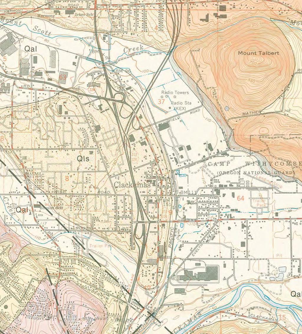
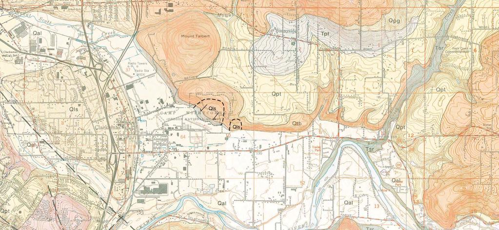
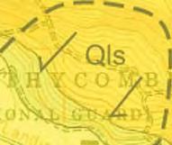
1 December 2010 Geology and Soils This section describes the local geology, soils, groundwater, and seismology in the Sunrise Project area. All of these factors affect the constructability of the project and how it might need to be specifically engineered, including methods to protect other features. Figure 51 and Figure 52 show the main local features of the geology and soils of the project area. Geology The geology of the Sunrise Project area has base layers of two types of bedrock overlain by a variety of deposits, followed by surface soils. The two types of bedrock units Boring Lavas and Sandy River Mudstone have different characteristics that could affect construction of the Sunrise Project. Boring Lavas consist of hard basalt, volcanic sediments, and areas with boulders. Boring Lavas mostly underlie the highland areas immediately north of the alignment and from Mount Talbert to the slopes of Rock Creek. Sandy River Mudstone has a finer, softer texture and is exposed along the slopes of Rock Creek and the Clackamas River (see Figure 51). Bedrock is likely to be encountered in the eastern portion of the project corridor and during construction of deep foundations, particularly in areas where the alignment encroaches on the south-facing slopes flanking most of the corridor. Both bedrock units are covered by near surface and surface deposits (called geologic units on Figure 51), such as constructed fill, alluvium (soils associated with the Clackamas River and its tributaries), landslide deposits, colluvium (produced by weathering of the Boring Lavas), and terrace deposits. The I-205 Interchange area to Rock Creek Junction contains the Boring Lavas, landslide soils, fills, alluvium, and [ 251 ] colluvium. Most of the Sandy River Mudstone is exposed along the toe of the Eastern Landslide and in the slopes along Rock Creek. Construction of the alignment would mostly be in the surface soils but, as noted in the preceding paragraph, could reach into the bedrock as well. Soils Alluvium is soil or sediments deposited by a river or other running water. Colluvium is sediment that has been deposited or built up at the bottom of a low grade slope or against a barrier on that slope, transported by gravity. Terrace deposit is a geological term for a flat platform of land created alongside of a river or sea, where, at some time in the past, the river has cut itself a deeper channel. The Geology and Soils Technical Report provides details on the following: Methods. Regional and local geology, landslides, subsurface soils, surficial soils, groundwater, and seismic settings. Environmental consequences: stability of cut slopes and excavation, groundwater, shrink/swell and erodible soils fill embankments, liquefaction, borrow and disposal sites. Possible mitigation measures for each environmental consequence. The near surface soils consist of clay, silt, sand, and gravel mixtures to depths of up to 20 feet, overlying gravel layers. Groundwater levels likely fluctuate in response to precipitation. The slopes north of the Sunrise Project alignment have shallow groundwater and groundwater springs or seeps. The groundwater depth is generally shallower in the I-205 Interchange and Midpoint areas than in the Rock Creek Junction area. Wetland areas have even shallower groundwater (see the previous Wetlands Section). Soils are shown on Figure 52. Most of the surface soils are described as moderately to severely wet and subject to erosion. In addition, they have a high plasticity, which means they have a tendency to shrink and swell and can present problems when used to support heavy structures. The area north of Camp Withycombe and east of the Union Pacific Railroad tracks is covered by Cove silty clay loam soils, a soil type susceptible to shrinking and swelling as its moisture content changes. The fluctuation in volume usually occurs unevenly and can be large enough to damage structures and pavements resting on or embedded in the soil. Chapter 3 Geology and Soils
2 December 2010 Two landslides have been mapped in the Midpoint area. One landslide (referred to as the Camp Withycombe Landslide) is in the northeastern portion of Camp Withycombe. The other landslide (referred to as the Eastern Landslide) is located approximately between SE 115 th Avenue and SE 119 th Avenue. The approximate locations of the two landslides are illustrated on Figure 51. There is evidence of recent landslide activity near the southeastern corner of the Camp Withycombe Landslide, but no documented evidence of instability at the Eastern Landslide at this time. Construction activities that encroach on the landslide areas could trigger further movement of the landslides. The general constraints of the underlying geology and soils of the Sunrise Project area apply to the Sunrise Project under all the alternatives. The more construction and excavation needed, the greater the chances of encountering geotechnical issues. Generally, the problems can be engineered to compensate for the constraints (see the Mitigation Measures for the Preferred Alternative section), but each engineering solution has different risks and costs associated with it. Because the road improvements under Alternative 1 No Build would involve so little ground disturbance compared to building the Sunrise Project, Alternative 1 would have little to no impacts. The main difference between Alternatives 2 and 3 is the degree and location of excavation that would be required for the midpoint interchange. Grading and earthwork present a potential risk of instability where local slopes are composed of soft and weak colluvium soils (mostly in the Midpoint area). The interchange at SE 122 nd Avenue under Alternative 2 would require grading that includes cuts of up to 40 feet high into the Eastern Landslide, and local slopes that could require slope stabilization. Cuts of the magnitude likely to be required by the project would have substantial impacts on the stability of the slopes. Cuts into the toes of the landslides could reactivate them. Alternative 3 would have less impact on the stability of the slopes compared to Alternative 2. In addition, Alternative 3 may not require temporary shoring and retaining structures to sustain the cut slopes. Up to 50 feet of fill could be needed for the Sunrise Project at various points. The fill and the embankments at the bridge approaches would cause settlement of several inches in some of the finer-grained soils. Appropriately designed embankment slopes should be relatively stable, but the estimate of the total amount of fill needed could increase as a result of the settlement. In addition, the settling could negatively affect adjacent structures and utilities. Structures and utilities sensitive to settlement near the fill embankments could require site-specific geotechnical investigations to protect them from potential impacts. Earthwork for construction could encounter cobbles, boulders, and hard intact Boring Lavas basalt. Particularly in the Rock Creek Junction area, construction of the entrance and exit ramps would require excavating to a depth of 40 to 60 feet. That depth of cut could reach to the Boring Lavas, entailing excavation of rock, gravel, cobbles, and boulders. On the other hand, the Boring Lavas could sustain near vertical cuts in the slopes. Because of the shallow groundwater within the upper 10 to 30 feet in the Rock Creek Junction area, removing water from the soil may be necessary for construction. The dewatering could have several effects, including settling of adjacent structures, drying adjacent wetlands, and lowering groundwater levels in wells. There appear to be no particular geotechnical advantages to selecting Design Options A-2, C-2, or D-2 over Alternatives 2 and 3. Design Option B-2 would have impacts similar to Alternative 3 and less impact than Alternative 2. Although cuts into the Eastern Landslide and local slope areas would be required, the cuts would be less deep, thereby reducing potential impacts on the stability of the slopes. Design Option C-3 would require deeper cuts into the slopes north of this area than Design Option C-2 would. East of SE 135 th Avenue, Design Option [ 252 ] Chapter 3 Geology and Soils
3 December 2010 C-3 would result in a permanent cut slope that extends to the top of the hillside, likely cutting through terrace deposits, colluvium, and Boring Lavas. The basalt can sustain the degree of the slope, but the colluvium could be more unstable during excavation. Groundwater seeps and shallow groundwater are likely to be encountered during construction of the cut slope, which would most likely require groundwater drainage control. While most slopes along this more northerly alignment generally appear to be stable, there is a groundwater spring and seeps are present just west of SE 142 nd Avenue. Design Option D-3 has a slight advantage related to the westbound exit ramps at Rock Creek Junction. Design Option D-2 and the design for Alternatives 2 and 3 place the westbound exit ramp deeper into the basalt knoll, whereas the more southerly alignment of the westbound exit ramp for Design Option D-3 would probably require less excavation in the knoll. Preferred Alternative Similar to Alternative 2, the Preferred Alternative impacts include slope instability due to excavation and benching into landslide and slopes; excavation of rock; excavation and handling of boulders; soft and wet soils in wetlands and shallow groundwater areas; springs/seeps on slopes; shrink/swell soils; erodible soils; settlement of foundation soils due to fill embankments; and localized, seismically induced liquefaction. It is estimated that the project would require excavation of about 1.97 million cubic yards and fill of about 3.82 million cubic yards of material. The Tolbert overcrossing portion of the Preferred Alternative will have soils and geology impact issues substantially the same as those described for Alternative 2 in the I-205 Interchange area. The Preferred Alternative in the Midpoint and Rock Creek Junction areas would have fewer impacts through those areas than the other options. Figure PA-47 is the geologic map and Figure PA-48 is the soils map for the Preferred Alternative. Groundwater conditions in the new areas of the Preferred Alternative are not likely to vary [ 253 ] significantly from those described for the other build alternatives. For example, construction groundwater control (dewatering) may be required because of the potential presence of shallow groundwater within the upper 10 to 30 feet in the Rock Creek Junction area. Construction dewatering has potential adverse impacts, including settlement of adjacent structures and drying of adjacent wetlands. In addition, the use of a dewatering system could reduce the production of existing groundwater wells in the vicinity. The slope gradient for the cut slopes in this segment would be varied, depending on soil types, depth to bedrock if present, bedrock strengths and jointing, and depth to groundwater. Several areas of the Preferred Alternative were not part of the evaluation of Alternative 2 and were added as part of the Preferred Alternative. In the I-205 Interchange area, the Preferred Alternative includes the construction or modification of three bridges including: (1) North Lawnfield Extension, (2) a railroad overcrossing at SE Tolbert Street connecting to the extension of SE Industrial Way, and (3) a lane widening of the existing bridge crossing the railroad at OR / (east of SE 82 nd Avenue). As a result, a feasibility evaluation of those areas was conducted in Construction of the three bridges is feasible using conventional foundations which may include spread footings, piles, or drilled shafts. Geotechnical investigations and design evaluations during the final design phase will determine the most appropriate foundations for the bridges. The two areas where impacts from the Preferred Alternative will be greatest are within the Midpoint area. Camp Withycombe and the Eastern Landslide, and steep slopes are between the Eastern Landslide and SE 135 th Avenue. The other area of concern is where erosion of the north bank has occurred in the Clackamas River near Rock Creek. The results of the feasibility evaluations conducted in 2009 are presented below. Chapter 3 Geology and Soils
4 December 2010 Camp Withycombe and Eastern Landslides and steep slope between the Eastern Landslide and SE 135 th Avenue The toe of the slope below the two older mapped landslides is adjacent to the shoulder of the westbound lane of the Preferred Alternative and associated on- and off-ramps at the intersection with SE 122 nd Avenue. Both landslides are potentially active and pose a risk to the corridor segment along the toe of the slopes in that area. The hillside area above the landslides contains private residences and roadways. The Preferred Alternative includes exit and entrance ramps associated with the overpass at the north end of the extension of SE 122 nd Avenue. The grading associated with the ramps would result in cuts of up to 50 feet along the toe of the existing steeper slopes and the toe of the Eastern Landslide. Erosion of the north bank of the Clackamas River There is a tight incision meander of the Clackamas River just south of the existing highway and the Preferred Alternative, east of SE 142 nd Avenue. Erosion of the northern riverbank is occurring along the incision meander. During site reconnaissance in June 2009, the bank was approximately 65 feet high with a near-vertical slope. Soils exposed in the riverbank consist predominantly of lightly cemented gravels with variable amounts of silt, clay, and sand. Although these sediments are capable of supporting a nearvertical exposure, the soils are typically poorly consolidated and subject to failure. Historic riverbank failures have occurred in this area, such as along the eastern side of the manufactured home park, and may encroach on the corridor in the future. ODOT does not anticipate the need for the Sunrise Project to be set back from the river in that location. Engineering solutions are available to minimize erosion and avoid a setback. [ 254 ] North Lawnfield Extension bridge The proposed bridge will be constructed at the northern end of the project to accommodate the extension of SE Lawnfield Road. Final design details for the bridge, such as length, width, number of spans, and type, are not available at this time. In general, the proposed bridge will be located on a westerly-descending slope in an area currently occupied by residential and light commercial development. Subsurface conditions in the area of the bridge would not be investigated until final design of the bridge and its foundations has been completed. The hillside is likely to be underlain by volcanic rocks and/or sediments of the Boring Lava Formation at depth. The nature and strength of the Boring Lava in the area is highly variable. It varies from deeply weathered volcanic rock that has decomposed to residual soil to hard basalt. Difficult excavation should be anticipated in this unit; local areas of weathered Boring Lava contain hard boulders of volcanic rock that can exceed 10 feet in diameter. The thickness of the flows, based on regional well logs, indicates that individual flows within the Boring Lavas are estimated to range from 100 to 200 feet thick. No readily apparent indications of slope instability, areas of accelerated erosion, or poor drainage were observed along the slopes in the general vicinity of the proposed bridge location. However, landslides are present on the hillsides east of the bridge site. The largest of these landslides is the aforementioned landslide located eastnortheasterly of Camp Withycombe, and it is suspected to be active based on topographic features (e.g., hummock topography and ponded depressions) and tilted trees. Earthquakes Crustal earthquakes (generally within depths of ten miles below the surface) are the most common source of earthquakes in the Portland region. Some of the shallow earthquake faults could be active in the Portland-Vancouver area. Three significant faults within 25 miles of the project area are believed to have undergone movement within the Chapter 3 Geology and Soils
5 December 2010 last 15,000 years. The closest of the three faults is the East Bank Fault (6 miles northwest), followed by the Canby-Molalla Fault (8 miles west). The Mount Angel Fault is approximately 24 miles southwest. ODOT has seismic design standards for bridges and overpasses. Liquefaction describes the behavior of loose saturated sands, which go from a solid state to the consistency of a heavy liquid, or reach a liquefied state. Earthquakes can cause liquefaction of loose, saturated soils that then lose their strength to support structures. Liquefaction would cause footings to lose their capacity to support the overhead structures, embankments to settle and spread laterally, and slopes to lose stability, and it would generally adversely affect any supporting structures in those soils. A combination of loose sand and low plasticity silt combined with shallow groundwater susceptible to liquefaction during earthquakes is present locally throughout the Sunrise Project area (see Figure 53, Fault Location Map). This condition is difficult to associate with specific alternatives or design options; therefore, the risks specific to each alternative and design option including the Preferred Alternative are unknown at this time. Indirect Effects The volume of excavation and fill and construction operations would result in a significant increase in truck traffic due to hauling of fill materials to and from the project site. This would likely result in congestion on local streets, pavement damage, noise and air pollution, and aggregate fill extraction (borrow pits). Construction in areas of shallow groundwater could require drying or dewatering them, which could lower adjacent groundwater levels, thus causing settling of adjacent structures, drying of adjacent wetlands, and increased risk of contamination migrating under the surface. Mitigation Measures for the Preferred Alternative Based on ODOT standard practices, the proposed roadway cuts required for the project would be technically feasible with proposed mitigation measures listed below. Stability of Cut Slopes and Excavation In the vicinity of landslides and slopes, mitigation will consist (if feasible) of avoiding impacting the toe of the existing slopes at the Camp Withycombe and Eastern landslides and local slopes located between Camp Withycombe and SE 135 th Avenue. Minimizing the impact to the slopes could include avoiding cuts and adjusting the roadway elevations. However, other geotechnical measures could also be used to support the slopes and accommodate grading. These measures could include placing denser fill along the toe of the slope (buttress fill) and/or use of retaining structures such as soldier pile and tieback and secant pile retaining walls. Multiple retaining walls could be benched into the slope to reduce the height of a single wall. Additional geotechnical exploration, analysis, and monitoring of both landslide areas should be conducted during final design to evaluate which mitigation measures are appropriate to support the slopes. Also, if grading along the slopes cannot be avoided, slope drainage (dewatering) and excavation (cut) should be done in short segments, and temporary and permanent retaining structures, or rock buttresses, installed. Dewatering could be required as a temporary measure during construction for deeper excavations to accommodate excavation for structures or utilities. Dewatering may also be permanent where the natural drainage paths are blocked by the addition of embankment fill. The details of any permanent drainage improvements or modifications will occur during final design with input from the civil engineer. Existing groundwater production wells should be taken into account in the design and construction of any dewatering systems that might be needed. [ 255 ] Chapter 3 Geology and Soils
6 December 2010 Limits on construction could include restricting the length, height, and duration of open excavations adjacent to steep slopes and mapped landslides, and could require that construction be completed only during dry conditions. Because of the critical nature of construction in these areas, additional measures to consider could include drainage improvements to prevent the accumulation of water in excavations, limits on construction traffic to reduce unnecessary ground vibration, and full-time observation by a geotechnical engineer or engineering geologist during construction. In addition, monitoring of both landslides is recommended to be completed before and during construction and on a long-term basis after construction to evaluate potential impacts to the existing slopes and new roads. Slope inclinometers, tiltmeters, and survey points could be used to monitor the landslides. foundations bearing on dense gravels that are present beneath potentially liquefiable deposits, as appropriate. Erodible Soils Erosion will be mitigated during construction by planning earthwork operations to limit the duration and exposure of erodible soils, using erosion and sediment control devices during earthwork construction, and directing surface water off-site through the existing storm system or suitable, erosion-protected discharge following the ODOT s Standard Specifications, Section 280, and Clackamas County erosion protections/control requirements. Because of the height of the exposed near-vertical slope, the risk to the proposed alignment near the incision meander of the north bank of the Clackamas River will require evaluation during final design. This will include slope stability analyses and evaluation of engineering alternatives to reduce the impacts of long-term erosion. Such solutions may include retaining walls and/or soil improvement. Embankment Fill and Sediment A site-specific geotechnical investigation will be performed to estimate the potential damage and required mitigation resulting from embankment dead loads. Soft, compressible soils should be replaced and ground/soil improvement made with either deep soil mixing or installation of displacement piles or reamed aggregate piers. Seismically-Induced Liquefaction Liquefaction settlement, where present, will be mitigated under embankment fills with ground improvement methods such as installation of rammed stone piers, stone columns, and removal and replacement of soft and potentially liquefiable soils. Bridge foundations will be supported on pile [ 256 ] Chapter 3 Geology and Soils

7 Qtb Qtb pt Qtb wx Qpg Figure 51 Geologic Map, Alternatives 2 and 3


8 Alternative F mi. 1A Aloha silt loam, 0 to 3 percent slopes 8B Bornstedt silt loam, 0 to 8 percent slopes 8C Bornstedt silt loam, 8 to 15 percent slopes 8D Bornstedt silt loam, 15 to 30 percent slopes 13B Cascade silt loam, 3 to 8 percent slopes 13C Cascade silt loam, 8 to 15 percent slopes 13D Cascade silt loam, 15 to 30 percent slopes 14C Cascade silt loam, stony substratum, 3 to 15 percent slopes 17 Clackamas silt loam 23C Cornelius silt loam, 8 to 15 percent slopes 25 Cove silt clay loam 30C Delena silt loam, 3 to 12 percent slopes 41 Huberly silt loam 53A Latourell loam, 0 to 3 percent slopes 53B Latourell loam, 3 to 8 percent slopes 70C Powell silt loam, 8 to 15 percent slopes 71B Quatama loam, 3 to 8 percent slopes 76B Salem silt loam, 0 to 7 percent slopes 84 Wapato silty clay loam 87A Willamette silt loam, gravelly substratum, 0 to 3 percent slopes 91A Woodburn silt loam, 0 to 3 percent slopes 91B Woodburn silt loam, 3 to 8 percent slopes 91C Woodburn silt loam, 8 to 15 percent slopes 92F Xerochrepts and Haploxerolls, very steep Figure 52 Surface Soils Map, Alternatives 2 and 3


9 N N BEAVERTON FAULT ZONE EAST BANK FAULT 217 OATFIELD FAULT 26 DAMASCUS-TICKLE CREEK FAULT CANBY-MOLALLA FAULT E PORTLAND HILLS FAULT BOLTON FAULT PROJECT SITE 205 No scale Sources: Kleinfelder, * Fault locations are approximate Source: or/van.html *Fault locations are approximate FNo Scale Figure 53 Fault Location Map SUNRISE PROJECT I-205 TO ROCK CREEK JUNCTION CLACKAMAS COUNTY, OREGON
10 2010 This page intentionally left blank


11 Qpg Tpt Qtb Qtb pt Qtb wx Figure PA-47 Qpg Geologic Map


12 F mi. 1A 8B 8C 8D 13B 13C 13D 14C 17 23C 25 30C Aloha silt loam, 0 to 3 percent slopes Bornstedt silt loam, 0 to 8 percent slopes Bornstedt silt loam, 8 to 15 percent slopes Bornstedt silt loam, 15 to 30 percent slopes Cascade silt loam, 3 to 8 percent slopes Cascade silt loam, 8 to 15 percent slopes Cascade silt loam, 15 to 30 percent slopes Cascade silt loam, stony substratum, 3 to 15 percent slopes Clackamas silt loam Cornelius silt loam, 8 to 15 percent slopes Cove silt clay loam Delena silt loam, 3 to 12 percent slopes 41 53A 53B 70C 71B 76B 84 87A 91A 91B 91C 92F Huberly silt loam Latourell loam, 0 to 3 percent slopes Latourell loam, 3 to 8 percent slopes Powell silt loam, 8 to 15 percent slopes Quatama loam, 3 to 8 percent slopes Salem silt loam, 0 to 7 percent slopes Wapato silty clay loam Willamette silt loam, gravelly substratum, 0 to 3 percent slopes Woodburn silt loam, 0 to 3 percent slopes Woodburn silt loam, 3 to 8 percent slopes Woodburn silt loam, 8 to 15 percent slopes Xerochrepts and Haploxerolls, very steep Figure PA-48 Surface Soils Map
3.18 GEOLOGY AND SOILS
 3.18 GEOLOGY AND SOILS This section discusses geologic resource concerns as they relate to the environment, public safety, and project design both during construction and after completion of the project.
3.12 Geology and Topography Affected Environment
 3 Affected Environment and Environmental Consequences 3.12 Geology and Topography 3.12.1 Affected Environment 3.12.1.1 Earthquakes Sterling Highway MP 45 60 Project Draft SEIS The Kenai Peninsula is predisposed
Impact : Changes to Existing Topography (Less than Significant)
") 4.2 Land Resources 4.2.1 Alternative A Proposed Action Impact 4.2.1-1: Changes to Existing Topography (Less than Significant) Development of the project site would involve grading and other earthwork as
4.2 Land Resources 4.2.1 Alternative A Proposed Action Impact 4.2.1-1: Changes to Existing Topography (Less than Significant) Development of the project site would involve grading and other earthwork as
IV. ENVIRONMENTAL IMPACT ANALYSIS G. GEOLOGY AND SOILS
 IV. ENVIRONMENTAL IMPACT ANALYSIS G. GEOLOGY AND SOILS The following section is based upon the City of El Segundo General Plan and General Plan EIR and addresses the following geologic issues: soil erosion,
IV. ENVIRONMENTAL IMPACT ANALYSIS G. GEOLOGY AND SOILS
 IV. ENVIRONMENTAL IMPACT ANALYSIS G. GEOLOGY AND SOILS The following section is a summary of the geotechnical report conducted for the proposed project. The Report of Geotechnical Investigation Proposed
Converse Consultants Geotechnical Engineering, Environmental & Groundwater Science, Inspection & Testing Services
 Converse Consultants Geotechnical Engineering, Environmental & Groundwater Science, Inspection & Testing Services Ms. Rebecca Mitchell Mt. San Antonio College Facilities Planning & Management 1100 North
GEOLOGY, SOILS, AND SEISMICITY
 4.9 GEOLOGY, SOILS, AND SEISMICITY 4.9.1 Introduction Information about the geological conditions and seismic hazards in the study area was summarized in the FEIR, and was based on the Geotechnical Exploration
GEOLOGY AND SOILS. This chapter summarizes geologic and geotechnical aspects of the site as they relate to the Project.
 9 GEOLOGY AND SOILS INTRODUCTION This chapter summarizes geologic and geotechnical aspects of the site as they relate to the Project. This chapter utilizes information from the following reports prepared
Mass Wasting. Revisit: Erosion, Transportation, and Deposition
 Mass Wasting Revisit: Erosion, Transportation, and Deposition While landslides are a normal part of erosion and surface processes, they can be very destructive to life and property! - Mass wasting: downslope
3.0 SUMMARY OF POTENTIAL GEOTECHNICAL IMPACTS AND MITIGATION MEASURES
 3.0 SUMMARY OF POTENTIAL GEOTECHNICAL IMPACTS AND MITIGATION MEASURES This section summarizes the principal geotechnical conditions that occur in the project area. The potential impact that each condition
2. Initial Summary of Preliminary Expert Opinion of Converse and Psomas Reports
 UNITED WALNUT TAXPAYERS PRELIMINARY REVIEW OF NEGATIVE GEOTECHNICAL AND GEOLOGICAL ASPECTS OF CONSTRUCTING EARTHFILL PAD FOR A SOLAR FARM ON THE WEST PARCEL - DRAFT 1. Introduction A licensed Engineering
Preliminary Geotechnical Evaluation Gooseberry Point Pedestrian Improvements Whatcom County, Washington SITE AND PROJECT DESCRIPTION
 File No. 12-100 Geotechnical & Earthquake Engineering Consultants Mr. Kevin Brown, P.E. Gray & Osborne, Inc. 3710 168 th Street NE, Suite B210 Arlington, Washington 98223 Subject: Draft Report Preliminary
IV. ENVIRONMENTAL IMPACT ANALYSIS E. GEOLOGY AND SOILS
 IV. ENVIRONMENTAL IMPACT ANALYSIS E. GEOLOGY AND SOILS INTRODUCTION This section evaluates potential impacts related to geology, including seismicity, and soils associated with development of the proposed
3.12 Geology and Topography Affected Environment
 3 Affected Environment and Environmental Consequences 3.12 Geology and Topography 3.12.1 Affected Environment 3.12.1.1 Earthquakes Sterling Highway MP 45 60 Project Final EIS The Kenai Peninsula is predisposed
IV. ENVIRONMENTAL IMPACT ANALYSIS E. GEOLOGY/SOILS
 IV. ENVIRONMENTAL IMPACT ANALYSIS E. GEOLOGY/SOILS The following discussion is based upon information contained in the Hollywood Redevelopment Plan Amendment EIR and a letter prepared by Geotechnologies,
CHAPTER GEOLOGICALLY HAZARDOUS AREAS Applicability Regulations.
 CHAPTER 19.07 GEOLOGICALLY HAZARDOUS AREAS 19.07.010 Applicability. Geologically hazardous areas may pose a threat to the health and safety of citizens when incompatible development is sited in areas of
4.11 Geology and Soils
 4.11 Geology and Soils 4.11.1 Introduction to Resources and Regulatory Requirements Geology and soil considerations important to the East Link Project include topography, geology, soil characteristics,
4.11 Geology and Soils
 4.11 Geology and Soils 4.11.1 Introduction to Resources and Regulatory Requirements Geology and soil considerations important to the East Link Project include topography, geology, soil characteristics,
June 9, R. D. Cook, P.Eng. Soils Engineer Special Services Western Region PUBLIC WORKS CANADA WESTERN REGION REPORT ON
 PUBLIC WORKS CANADA WESTERN REGION REPORT ON GEOTECHNICAL INVESTIGATION PROPOSED MARTIN RIVER BRIDGE MILE 306.7 MACKENZIE HIGHWAY Submitted by : R. D. Cook, P.Eng. Soils Engineer Special Services Western
14 Geotechnical Hazards
 Volume 2: Assessment of Environmental Effects 296 14 Geotechnical Hazards Overview This Chapter provides an assessment of the underlying geotechnical conditions to identify: any potential liquefaction
Geotechnical Engineering and Resilience
 Chapter 14 Part G VOLUME 2 Geotechnical Engineering and Resilience Page 192 Overview Key geotechnical aspects of the Project include: Cut slopes in dune sand, including erodibility and erosion protection;
IV. ENVIRONMENTAL IMPACT ANALYSIS E. GEOLOGY AND SOILS
 IV. ENVIRONMENTAL IMPACT ANALYSIS E. GEOLOGY AND SOILS The following analysis is based on the Geotechnical Investigation Report, Proposed Mid-Rise Multi- Family Residential Development Project Wetherly
3.8 Geology/Soils. Environmental Setting. Topography. Geology and Soils
 3.8 Geology/Soils This section examines whether implementation of the 2004 Land Use Mobility Elements, Zoning Code Revisions, and Central District Specific Plan the will expose people or structures to
IV. ENVIRONMENTAL IMPACT ANALYSIS E. GEOLOGY/SOILS
 IV. ENVIRONMENTAL IMPACT ANALYSIS E. GEOLOGY/SOILS Except where otherwise noted, the following Section is based on the Preliminary Geotechnical Investigation, Proposed Medical Office Buildings and Mixed-Use
ENGINEER S CERTIFICATION OF FAULT AREA DEMONSTRATION (40 CFR )
") PLATTE RIVER POWER AUTHORITY RAWHIDE ENERGY STATION BOTTOM ASH TRANSFER (BAT) IMPOUNDMENTS LARIMER COUNTY, CO ENGINEER S CERTIFICATION OF FAULT AREA DEMONSTRATION (40 CFR 257.62) FOR COAL COMBUSTION RESIDUALS
PLATTE RIVER POWER AUTHORITY RAWHIDE ENERGY STATION BOTTOM ASH TRANSFER (BAT) IMPOUNDMENTS LARIMER COUNTY, CO ENGINEER S CERTIFICATION OF FAULT AREA DEMONSTRATION (40 CFR 257.62) FOR COAL COMBUSTION RESIDUALS
IV. ENVIRONMENTAL IMPACT ANALYSIS E. GEOLOGY AND SOILS
 IV. ENVIRONMENTAL IMPACT ANALYSIS E. GEOLOGY AND SOILS The following section is a summary of the geotechnical report conducted for the Proposed Project. The Geotechnical Engineering Investigation (the
The last three sections of the main body of this report consist of:
 Threatened and Endangered Species Geological Hazards Floodplains Cultural Resources Hazardous Materials A Cost Analysis section that provides comparative conceptual-level costs follows the Environmental
Geology, Soils, and Seismicity
 Section 3.8 Geology, Soils, and Seismicity Introduction This section generally evaluates the effects of the alternatives analyzed in this Supplemental DEIS with regard to geology, soils and seismicity.
Hydrogeological Assessment for Part of Lots 2 and 3, Concession 5, Township of Thurlow, County of Hastings 1.0 INTRODUCTION. 1.
 February 10,2017 25506400 Ontario Ltd. Foxboro, ON Attention: Brad Newbatt Re: Hydrogeological Assessment for Part of Lots 2 and 3, Concession 5, Township of Thurlow, County of Hastings 1.0 INTRODUCTION
Guidelines for Site-Specific Seismic Hazard Reports for Essential and Hazardous Facilities and Major and Special-Occupancy Structures in Oregon
 Guidelines for Site-Specific Seismic Hazard Reports for Essential and Hazardous Facilities and Major and Special-Occupancy Structures in Oregon By the Oregon Board of Geologist Examiners and the Oregon
Appendix M Preliminary Geotechnical Report, SR 32 Widening Project Study Report
 Appendix M Preliminary Geotechnical Report, SR 32 Widening Project Study Report November 3, 2005 Mr. Chris Rockway 7300 Folsom Boulevard, Suite 203 Sacramento, California 95826 Attention: Matt Brogan
5.5 GEOLOGY/SOILS EXISTING CONDITIONS. Regulatory Setting
 5.5 GEOLOGY/SOILS This section describes existing environmental conditions related to geology and soils in the project area, including W-19, the disposal site, and beach placement sites proposed as part
Soil Mechanics. Chapter # 1. Prepared By Mr. Ashok Kumar Lecturer in Civil Engineering Gpes Meham Rohtak INTRODUCTION TO SOIL MECHANICS AND ITS TYPES
 Soil Mechanics Chapter # 1 INTRODUCTION TO SOIL MECHANICS AND ITS TYPES Prepared By Mr. Ashok Kumar Lecturer in Civil Engineering Gpes Meham Rohtak Chapter Outlines Introduction to Soil Mechanics, Soil
SLOPE STABILITY EVALUATION AND ACCEPTANCE STANDARDS
 INFORMATION BULLETIN / PUBLIC - BUILDING CODE REFERENCE NO.: LABC 7006.3, 7014.1 Effective: 01-01-2017 DOCUMENT NO.: P/BC 2017-049 Revised: 12-21-2016 Previously Issued As: P/BC 2014-049 SLOPE STABILITY
ES 104 # 5 EARTHQUAKES:
 ES 104 Laboratory # 5 EARTHQUAKES: Epicenter Determination, Seismic Waves, and Hazards Introduction Earthquakes are vibrations of Earth caused by large releases of energy that accompany volcanic eruptions,
Engineer. Engineering. Engineering. (in-ja-neer ) A person trained and skilled in any of the various branches of engineering: a civil engineer
 A person trained and skilled in any of the various branches of engineering: a civil engineer") Engineer (in-ja-neer ) A person trained and skilled in any of the various branches of engineering: a civil engineer (Random House Webster s College Dictionary, 1991) CE100 Introduction to Civil Geotechnical
Engineer (in-ja-neer ) A person trained and skilled in any of the various branches of engineering: a civil engineer (Random House Webster s College Dictionary, 1991) CE100 Introduction to Civil Geotechnical
Foundations on Deep Alluvial Soils
 Canterbury Earthquakes Royal Commission Hearings 25 October 2011, Christchurch GEO.CUB.0001.1-35.1 Foundations on Deep Alluvial Soils Misko Cubrinovski, Ian McCahon, Civil and Natural Resources Engineering,
HISTORY OF CONSTRUCTION FOR EXISTING CCR SURFACE IMPOUNDMENT PLANT GASTON ASH POND 40 CFR (c)(1)(i) (xii)
(1)(i) (xii)") HISTORY OF CONSTRUCTION FOR EXISTING CCR SURFACE IMPOUNDMENT PLANT GASTON ASH POND 40 CFR 257.73(c)(1)(i) (xii) (i) Site Name and Ownership Information: Site Name: E.C. Gaston Steam Plant Site Location:
HISTORY OF CONSTRUCTION FOR EXISTING CCR SURFACE IMPOUNDMENT PLANT GASTON ASH POND 40 CFR 257.73(c)(1)(i) (xii) (i) Site Name and Ownership Information: Site Name: E.C. Gaston Steam Plant Site Location:
Converse Consultants Geotechnical Engineering, Environmental & Groundwater Science, Inspection & Testing Services
 Converse Consultants Geotechnical Engineering, Environmental & Groundwater Science, Inspection & Testing Services July 27, 2017 Ms. Rebecca Mitchell Mt. San Antonio College Facilities Planning & Management
Appendix F4.11 Geologic Unit Summaries, Hazard Areas, and Boring Locations
 Appendix F4.11 Geologic Unit Summaries, Hazard Areas, and Boring Locations Appendix F4.11 Geologic Unit Summaries and Hazard Areas TABLE F4.11-1 Summary of Geologic Units and their Engineering Properties
ENCE 3610 Soil Mechanics. Site Exploration and Characterisation Field Exploration Methods
 ENCE 3610 Soil Mechanics Site Exploration and Characterisation Field Exploration Methods Geotechnical Involvement in Project Phases Planning Design Alternatives Preparation of Detailed Plans Final Design
SLOPE STABILITY EVALUATION AND ACCEPTANCE STANDARDS
 INFORMATION BULLETIN / PUBLIC - BUILDING CODE REFERENCE NO.: LAMC 98.0508 Effective: 1-26-84 DOCUMENT NO. P/BC 2002-049 Revised: 11-1-02 Previously Issued As: RGA #1-84 SLOPE STABILITY EVALUATION AND ACCEPTANCE
1 PROJECT BACKGROUND. August 14, Alberta Transportation Central Region #401, Street Red Deer, Alberta T4N 6K8
 August 14, 2013 Alberta Transportation Central Region #401, 4902 51 Street Red Deer, Alberta T4N 6K8 Mr. Dennis Grace, P.Eng. Construction Engineer Dear Mr. Grace: Central Region Geohazard Assessment 2013
August 10, 2007 File:
 August 10, 2007 File: 15-85-72 Alberta Infrastructure and Transportation Room 301, Provincial Building 9621-96 Avenue Peace River, AB T8S 1T4 Attention: Mr. Ed Szmata PEACE REGION (PEACE HIGH LEVEL AREA)
4.9 GEOLOGY AND SOILS
 4.9 GEOLOGY AND SOILS 4.9.1 EXISTING CONDITIONS TOPOGRAPHY AND RELIEF Zone 40 is located in the central portion of Sacramento County. The topography of the county is represented by three physiographic
APPALACHIAN COLLUVIAL
 LANDSLIDE PROBLEMS ON APPALACHIAN COLLUVIAL SLOPES Geohazards in Transportation in the Appalachian Region Charleston, WV August 5 7, 2008 RICHARD E. GRAY DIGIOIA, GRAY & ASSOCIATES, LLC. 570 BEATTY ROAD
Slope Stability Evaluation Ground Anchor Construction Area White Point Landslide San Pedro District Los Angeles, California.
 Slope Stability Evaluation Ground Anchor Construction Area White Point Landslide San Pedro District Los Angeles, California Submitted To: Mr. Gene Edwards City of Los Angeles Department of Public Works
Name. 4. The diagram below shows a soil profile formed in an area of granite bedrock. Four different soil horizons, A, B, C, and D, are shown.
 Name 1. In the cross section of the hill shown below, which rock units are probably most resistant to weathering? 4. The diagram below shows a soil profile formed in an area of granite bedrock. Four different
Seismic Reflection Imaging across the Johnson Ranch, Valley County, Idaho
 Seismic Reflection Imaging across the Johnson Ranch, Valley County, Idaho Report Prepared for the Skyline Corporation Lee M. Liberty Center for Geophysical Investigation of the Shallow Subsurface (CGISS)
4.5 GEOLOGY AND SOILS
 4.5 GEOLOGY AND SOILS This section addresses the project site geology and soils and analyzes potential changes that would result from development of the Wye Specific Plan project. 4.5.1 Environmental Setting
Mitigation of Liquefaction Potential Using Rammed Aggregate Piers
 ASCE 2011 557 Mitigation of Liquefaction Potential Using Rammed Aggregate Piers R.W. Rudolph, M. ASCE, G.E. 1, B. Serna, M. ASCE, P.E. 2, and T. Farrell, M. ASCE, G.E. 3 1 Principal Consultant, ENGEO,
CENTRAL REGION GEOHAZARDS RISK ASSESSMENT SITE INSPECTION FORM
 SITE NUMBER AND NAME C55 H861:02 Slide LEGAL DESCRIPTION NW 14-40-14-W4 CENTRAL REGION GEOHAZARDS RISK ASSESSMENT SITE INSPECTION FORM HIGHWAY & KM NAD 83 COORDINATES N 5811217 E 437291 PREVIOUS INSPECTION
Setting MOUNTAIN HOUSE NEIGHBORHOODS I AND J INITIAL STUDY 5. ENVIRONMENTAL CHECKLIST 6. GEOLOGY AND SOILS. Issue
 Issue Less Than Significant or No Impact Potential Significant Impact Adequately Addressed in MEIR MEIR Required Additional Review: No Significant Impact Less Than Significant Impact Due to Mitigation
4.6 GEOLOGY AND SOILS
 4.6 GEOLOGY AND SOILS The purpose of the Geology and Soils section is to evaluate whether the proposed project would expose people or structures to major geotechnical hazards or substantially contribute
Date: April 2, 2014 Project No.: Prepared For: Mr. Adam Kates CLASSIC COMMUNITIES 1068 E. Meadow Circle Palo Alto, California 94303
 City of Newark - 36120 Ruschin Drive Project Draft Initial Study/Mitigated Negative Declaration Appendix C: Geologic Information FirstCarbon Solutions H:\Client (PN-JN)\4554\45540001\ISMND\45540001 36120
3.10 GEOLOGY/SOILS/SEISMIC/TOPOGRAPHY
 3.10 GEOLOGY/SOILS/SEISMIC/TOPOGRAPHY The information in this section is based on the Geotechnical Final Report (January 2010) and Geotechnical Memorandum for the northern portion of the Study Area (Department
Table 5-1 Sampling Program Summary for Milltown Ford Avenue Redevelopment Area, NJ.
 Table 5- Sampling Program Summary for Milltown Ford Avenue Redevelopment Area, NJ. Transformer Pads (9 pads: PAD 9) Evaluate if PCBs presently exist in soils adjacent to, and/or beneath the transformer
Pierce County Department of Planning and Land Services Development Engineering Section
 Page 1 of 7 Pierce County Department of Planning and Land Services Development Engineering Section PROJECT NAME: DATE: APPLICATION NO.: PCDE NO.: LANDSLIDE HAZARD AREA (LHA) GEOLOGICAL ASSESSMENT REPORT
SURFACE GEOLOGY AND LIQUEFACTION SUSCEPTIBILITY IN THE INNER RIO GRANDE VALLEY NEAR ALBUQUERQUE, NEW MEXICO
 SURFACE GEOLOGY AND LIQUEFACTION SUSCEPTIBILITY IN THE INNER RIO GRANDE VALLEY NEAR ALBUQUERQUE, NEW MEXICO Keith I. Kelson, Christopher S. Hitchcock, and Carolyn E. Randolph William Lettis & Associates,
Which map shows the stream drainage pattern that most likely formed on the surface of this volcano? A) B)
 B)") 1. When snow cover on the land melts, the water will most likely become surface runoff if the land surface is A) frozen B) porous C) grass covered D) unconsolidated gravel Base your answers to questions
1. When snow cover on the land melts, the water will most likely become surface runoff if the land surface is A) frozen B) porous C) grass covered D) unconsolidated gravel Base your answers to questions
Stream Geomorphology. Leslie A. Morrissey UVM July 25, 2012
 Stream Geomorphology Leslie A. Morrissey UVM July 25, 2012 What Functions do Healthy Streams Provide? Flood mitigation Water supply Water quality Sediment storage and transport Habitat Recreation Transportation
KDOT Geotechnical Manual Edition. Table of Contents
 KDOT Geotechnical Manual 2007 Edition The KDOT Geotechnical Manual is available two volumes. Both volumes are very large electronic (pdf) files which may take several minutes to download. The table of
IV. ENVIRONMENTAL IMPACT ANALYSIS E. GEOLOGY/SEISMIC HAZARDS
 IV. ENVIRONMENTAL IMPACT ANALYSIS E. GEOLOGY/SEISMIC HAZARDS 1. ENVIRONMENTAL SETTING The following analysis of geology and seismic hazards for the Middle School Project is based on the Report of Geotechnical
GEOTECHNICAL ENGINEERING SERVICES DUE DILIGENCE STUDY OFFICE OF HAWAIIAN AFFAIRS (OHA) SETTLEMENT PARCELS KAKA AKO, OAHU, HAWAII
 SETTLEMENT PARCELS KAKA AKO, OAHU, HAWAII") Geotechnical Engineering and Drilling Services Mr. Randall F. Sakumoto McCorriston Miller Mukai MackKinnon LLP P.O. Box 2800 Honolulu, HI 968013 Dear Mr. Sakumoto: GEOTECHNICAL ENGINEERING SERVICES DUE
Geotechnical Engineering and Drilling Services Mr. Randall F. Sakumoto McCorriston Miller Mukai MackKinnon LLP P.O. Box 2800 Honolulu, HI 968013 Dear Mr. Sakumoto: GEOTECHNICAL ENGINEERING SERVICES DUE
Figure 1 The map shows the top view of a meandering stream as it enters a lake. At which points along the stream are erosion and deposition dominant?
 1. In which type of climate does chemical weathering usually occur most rapidly? 1. hot and dry 3. cold and dry 2. hot and wet 4. cold and wet 2. Figure 1 The map shows the top view of a meandering stream
Prof. B V S Viswanadham, Department of Civil Engineering, IIT Bombay
 19 Module 5: Lecture -1 on Stability of Slopes Contents Stability analysis of a slope and finding critical slip surface; Sudden Draw down condition, effective stress and total stress analysis; Seismic
10. GEOTECHNICAL EXPLORATION PROGRAM
 Geotechnical site investigations should be conducted in multiple phases to obtain data for use during the planning and design of the tunnel system. Geotechnical investigations typically are performed in
5.11 Geology and Soils
 5.11 Geology and Soils 5.11 GEOLOGY AND SOILS This section evaluates the geologic and seismic conditions within the City of Azusa and evaluates the potential for geologic hazard impacts associated with
How & Where does infiltration work? Summary of Geologic History Constraints/benefits for different geologic units
 June 26, 2007: Low Impact Development 1 Associated Earth Sciences, Inc. Associated Earth Sciences, Inc. Presented by: Matthew A. Miller, PE April 24, 2012 How & Where does infiltration work? Summary of
PEACE REGION GRANDE PRAIRIE GEOHAZARD RISK ASSESSMENT SITE INSPECTION FORM NAD 83 COORDINATES N 6,178,811 E 403,309
 PEACE REGION GRANDE PRAIRIE GEOHAZARD RISK ASSESSMENT SITE INSPECTION FORM SITE NUMBER GP-4a LEGAL DESCRIPTION LSD 12-10-78-4-W6M SITE NAME Burnt River Bridge - West Approach Slide HIGHWAY & KM Hwy 49:06
Page 1. Name:
 Name: 1) Which event is the best example of erosion? dissolving of rock particles on a limestone gravestone by acid rain breaking apart of shale as a result of water freezing in a crack rolling of a pebble
 FIGURES 200 200 200 SW 175TH AVE 350 SW SCHOLLS FERRY RD SW FRIENDLY LN Area 64 SW ROY ROGERS RD 300 250 SW ONEILL CT SW LUKE LN SW LEEDING LN SW TUSCANY ST SW 164TH AVE SW BULL MOUNTAIN RD SW 164TH AVE
PHYSICAL SCIENCE FINAL
 PHYSICAL SCIENCE FINAL Liquefaction Doreen Wallace, Tesla Grogan, Amber Ward, Erik Garcia, Cinthia Salas, Alexis Albers Liquefaction What is it? Conditions needed How it works Effects of Liquefaction Soil
SOIL INVESTIGATION REPORT. PROPOSED HOUSING DEVELOPMENT PROJECT Coral Spring, Trelawny, Jamaica.
 SOIL INVESTIGATION REPORT PROPOSED HOUSING DEVELOPMENT PROJECT Coral Spring, Trelawny, Jamaica. Prepared for: FCS Consultants 7a Barbados Avenue Kingston 5, Jamaica Prepared by: NHL Engineering Limited
3.4 Typical Soil Profiles
 SEI.UoC.0002.11 Figure 4. Streams in central Christchurch as mapped in March 1850, superposed on aerial photography captured on 24 February 2011. Streams digitised from the Black Map of Christchurch (March
16 January 2018 Job Number: RICHARD NEWMAN C\- CLARK FORTUNE MCDONALD AND ASSOCIATES PO BOX 553 QUEENSTOWN
 16 January 2018 Job Number: 50595 RICHARD NEWMAN C\- CLARK FORTUNE MCDONALD AND ASSOCIATES PO BOX 553 QUEENSTOWN CHANSEN@CFMA.CO.NZ STORMWATER DISPOSAL ASSESSMENT Dear Richard, RDAgritech were requested
CASE STUDIES. Introduction
 Introduction The City of Winston-Salem faces the challenge of maintaining public infrastructure (e.g., water and sewer lines, storm drains, roads, culverts and bridges) while minimizing the potential impacts
KANSAS GEOLOGICAL SURVEY Open File Report LAND SUBSIDENCE KIOWA COUNTY, KANSAS. May 2, 2007
 KANSAS GEOLOGICAL SURVEY Open File Report 2007-22 LAND SUBSIDENCE KIOWA COUNTY, KANSAS Prepared by Michael T. Dealy L.G., Manager, Wichita Operations SITE LOCATION The site was approximately four miles
ATTACHMENT A PRELIMINARY GEOTECHNICAL SUMMARY
 ATTACHMENT A PRELIMINARY GEOTECHNICAL SUMMARY Kevin M. Martin, P.E. KMM Geotechnical Consultants, LLC 7 Marshall Road Hampstead, NH 0384 603-489-6 (p)/ 603-489-8 (f)/78-78-4084(m) kevinmartinpe@aol.com
3.10 GEOLOGY AND SOILS
 3.10 GEOLOGY AND SOILS This section evaluates the potential impacts of the proposed project on geology, soils, and seismic hazards. This evaluation is based on the Preliminary Geotechnical Investigation
Portland Water Bureau. Preparing Portland s Water Supply for The Big One. July 11, Tim Collins, P.E., G.E.
 Portland Water Bureau Preparing Portland s Water Supply for The Big One July 11, 2018 Tim Collins, P.E., G.E. Presentation Outline Portland water system overview Pacific Northwest seismic hazards Building
Assessment Schedule 2015 Earth and Space Science: Demonstrate understanding of the causes of extreme Earth events in New Zealand (91191)
") NCEA Level 2 Earth and Space Science (91191) 2015 page 1 of 6 Assessment Schedule 2015 Earth and Space Science: Demonstrate understanding of the causes of extreme Earth events in New Zealand (91191) Evidence
NCEA Level 2 Earth and Space Science (91191) 2015 page 1 of 6 Assessment Schedule 2015 Earth and Space Science: Demonstrate understanding of the causes of extreme Earth events in New Zealand (91191) Evidence
 265 Dalewood Way alteration permit #2016/02/17/9761 June 30, 2016 Appeal #16-109 Deck at Rear due to conflict with Slope Protection Act A. Executive Summary: We are in receipt of the Notification of Structural
Subsurface Geology of the Kennebec River
 Maine Geologic Facts and Localities July, 1998 Subsurface Geology of the Kennebec River 43 54 40.75 N, 69 48 29.01 W Text by Daniel B. Locke, Department of Agriculture, Conservation & Forestry 1 Map by
4.5 GEOLOGY AND SOILS
 4.5.1 Setting 4.5 GEOLOGY AND SOILS a. Regional Geology. The is located in the south central Santa Cruz Mountains in the heart of the Central Coast ranges of California. This is a seismically active region
Assessing Slope Instabilities. Victoria Leffel & Joey Franzino
 Assessing Slope Instabilities Victoria Leffel & Joey Franzino Slope Stability and Landslides Today s Presentation: Slope instability and landslide terms will be used interchangeably Landslide: downward
2.10 Geology/Soils/Seismic/Topography
 2.10 Geology/Soils/Seismic/Topography 2.10.1 Regulatory Setting This section discusses geology, soils, and seismic concerns as they relate to public safety and project design. Earthquakes are prime considerations
Remediation of Soft Clay Utilizing the Dry Mix Method. of Batavia, New York to its discharge into the Niagara River at Tonawanda, New York.
 Introduction Tonawanda Creek meanders as it flows in a generally westerly direction from its headwaters east of Batavia, New York to its discharge into the Niagara River at Tonawanda, New York. The geologic
Re: Steep Slope Assessment for 2465 Waverly Drive, Blind Bay, BC; Legal Address: Lot 39, Section 18, Township 22, Range 10, Plan 25579, W6M, KDYD.
 OEL File 1563-1 May 30, 2017 Doug Wall PO Box 774 Salmon Arm, BC V1E 4N7 Re: Steep Slope Assessment for 2465 Waverly Drive, Blind Bay, BC; Legal Address: Lot 39, Section 18, Township 22, Range 10, Plan
patersongroup Consulting Engineers April 20, 2010 File: PG1887-LET.01R Novatech Engineering Consultants Suite 200, 240 Michael Cowpland Drive
 patersongroup April 20, 2010 File: PG1887-LET.01R Novatech Engineering Consultants Suite 200, 240 Michael Cowpland Drive Ottawa, Ontario K2M 1P6 Attention: Mr. Adam Thompson Consulting Engineers 28 Concourse
GEOTECHNICAL POLICIES AND PROCEDURES MANUAL CHAPTER 5 GEOTECHNICAL INVESTIGATION PLANNING GUIDELINES
 GEOTECHNICAL POLICIES AND PROCEDURES MANUAL CHAPTER 5 GEOTECHNICAL INVESTIGATION PLANNING GUIDELINES GEOTECHNICAL INVESTIGATION PLANNING GUIDELINES 5-i TABLE OF CONTENTS 1. PURPOSE... 1 2. INTRODUCTION...
 R-1 Conveyor Relocation Project Legend 0 500 1000 1500 ft. This map is a user generated static output from an Internet mapping site and is for general reference only. Data layers that appear on this map
PENNSYLVANIA DEPARTMENT OF TRANSPORTATION ENGINEERING DISTRICT 3-0
 PENNSYLVANIA DEPARTMENT OF TRANSPORTATION ENGINEERING DISTRICT 3-0 LYCOMING COUNTY S.R.15, SECTION C41 FINAL HYDROLOGIC AND HYDRAULIC REPORT STEAM VALLEY RUN STREAM RELOCATION DATE: June, 2006 REVISED:
Landslide FE Stability Analysis
 Landslide FE Stability Analysis L. Kellezi Dept. of Geotechnical Engineering, GEO-Danish Geotechnical Institute, Denmark S. Allkja Altea & Geostudio 2000, Albania P. B. Hansen Dept. of Geotechnical Engineering,
R.M.HARW & ASSOCIATES LTD. GEOTECHNICAL INVESTIGATION PROPOSED BRIDGE SITE. HELAVA CREEKl MILE MACKENZIE HIGHWAY E-2510 OCTOBER 16, 1973
 El R.M.HARW & ASSOCIATES LTD. GEOTECHNICAL INVESTIGATION PROPOSED BRIDGE SITE HELAVA CREEKl MILE 616.4 MACKENZIE HIGHWAY E-2510 OCTOBER 16, 1973 R,M,HARDV & ASSOCIATES LTD. CONSULTING ENGINEERING & TESTING
FROST HEAVE. GROUND FREEZING and FROST HEAVE
 FROST HEAVE The temperature of soils near the ground surface reflects the recent air temperatures. Thus, when the air temperature falls below 0 C (32 F) for extended periods, the soil temperature drops
Topic 6: Weathering, Erosion and Erosional-Deposition Systems (workbook p ) Workbook Chapter 4, 5 WEATHERING
 Workbook Chapter 4, 5 WEATHERING") Topic 6: Weathering, Erosion and Erosional-Deposition Systems (workbook p. 95-125) Workbook Chapter 4, 5 THE BIG PICTURE: Weathering, erosion and deposition are processes that cause changes to rock material
Topic 6: Weathering, Erosion and Erosional-Deposition Systems (workbook p. 95-125) Workbook Chapter 4, 5 THE BIG PICTURE: Weathering, erosion and deposition are processes that cause changes to rock material
UGRC 144 Science and Technology in Our Lives/Geohazards
 UGRC 144 Science and Technology in Our Lives/Geohazards Flood and Flood Hazards Dr. Patrick Asamoah Sakyi Department of Earth Science, UG, Legon College of Education School of Continuing and Distance Education
Wells Truck Climbing Lane Elko County
 Wells Truck Climbing Lane Elko County August 23, 2018 STATE OF NEVADA DEPARTMENT OF TRANSPORTATION MATERIALS DIVISION GEOTECHNICAL SECTION GEOTECHNICAL REPORT WELLS TRUCK CLIMBING LANE ELKO COUNTY August
REPORT OF PRELIMINARY GEOTECHNICAL EXPLORATION
 REPORT OF PRELIMINARY GEOTECHNICAL EXPLORATION ENKA INTERMEDIATE SCHOOL Sand Hill Road Candler, North Carolina Prepared For: BUNCOMBE COUNTY SCHOOLS Prepared By: AMEC ENVIRONMENT & INFRASTRUCTURE, INC.