Brittle structures in the south-western corner of the Särkijärvi open pit, Siilinjärvi carbonatite occurrence
|
|
|
- Sharlene Owen
- 5 years ago
- Views:
Transcription

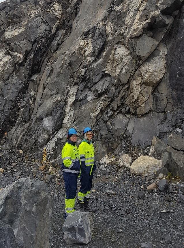
1 Report for YARA Suomi Oy Report GTK/594/03.02/2017 Work report 81/2017 Brittle structures in the south-western corner of the Särkijärvi open pit, Siilinjärvi carbonatite occurrence Matti Pajunen; Geological Survey of Finland Aleksi Salo, Mikko Suikkanen & Aki-Kimmo Ullgren; YARA Suomi Oy

2 GEOLOGIAN TUTKIMUSKESKUS KUVAILULEHTI Päivämäärä / ~ GTK/594/03.02/2017 Ttkija1 Matti Pajunen; GTK Aleksi Salo; YARA Suomi Oy Mikko Suikkanen; Y ARA Suomi Oy Aki Ullgren; YARA Suomi Oy Raponinla,; Work n!oort T olmeksianla) YARA Suomi Oy B~~iollimi Brinle structures in the south-western corner of the Särkijärviopen pit, Siilinjärvi c.arbonatite occurrence Jlbisle!Rla Report describes tectonic structures in the south-westem comer of the Särkijärvi open pii, Siilinjärvi RllQ~I2 hqq~ -carbonatite ore. The study is based on one-week field study and preliminary descriptions of ductile and brittle structures and kinematics of faulting and jointing. ~:111~ (~ OJOOIII~tllte ) Ductile structures. faulting, jointing, Siilinjärvi. Munlitoetlin n alut (m... ltanl. kunla, kylt, osiruym&) S iilinjä rvi~horite-carbonatite ore Komalehdel horite-carbonatite ore MUU11itdol Alkislourjan nimi ArtdstO!unnus Kotona issivumiira Kieli Hlnt.luiiOsws 38 p. English oublic YltsikkO ja vastuualue Kalliorakentaminen ja sijoituspaikat KAS ~slnlm27 Hannu Lahtinen Hanketunnus Ale~nys.. "~ - Matti Paiunen 7
3 Contents 1. Introduction 2. Geological outlines 2.1. Lithology in the study area 3. Study sites and data 4. Ductile structures 4.1. D1 event 4.2. D2 event 4.3. D3 event 5. Faults 6. Joints 6.1. Fault and joint relations 6.2. Rotational opening of joint sets 6.3. Steep joints indicating extension 6.4. Diorite ore contact and the block structures in diorite 6.5. Horizontal joints in the upper part of the open pit 6.6. Block structures in diorite 6.7. Correlation of photogrammetry/field measurements 6.8. Summary of jointing patterns 7. Problem sites 8. Summary 9. References Appendices
4
5 1 1. Introduction The Siilinjärvi alkaline complex, the first carbonatite occurrence found in Finland, is located ca. 5 km west of Siilinjärvi village to the north of Kuopio city. It is situated close to the Svecofennian-Archaean boundary zone as a steep, 16 km long and up to 1.5 km wide, N-S trending occurrence (Figure 1). The occurrence is divided into smaller parts in the north. The ore composes of glimmerite-carbonatite unit that at the Särkijärvi open pit shows its maximum width of 900 m. The mining started in Siilinjärvi in The theme of this study is to preliminary analyze the structural characteristics in the southwestern corner of the Särkijärvi open pit (Figure 1). The main purpose was to concentrate on brittle structures, faulting and jointing. The description of ductile structures is based only on cursory observations. One task is to correlate the observed joint data to the photogrammetric data collected by the YARA Suomi Oy (YARA in the following) from the same open pit walls. Attention was put on brittle structures that may cause stability problems on the pit slopes. The field work was made in October 16-12, 2017 and some mentoring to observe the jointing patterns and fault characteristics was part of this visit. The geologists Aleksi Salo, Aki Ullgren and Mikko Suikkanen from YARA Finland Oy took part in the field work. 2. Geological outlines The Siilinjärvi alkaline complex is geologically rather simple, and there are only few studies dealing with its lithological and structural characteristics. Puustinen (1971) gave the first geological analysis of the occurrence and proposed its magmatic origin. Härmälä (1981) described the mineralogy and process mineralogy of the Siilinjärvi apatite ore. They both (Puustinen 1971 and Härmälä 1981) suggested that the glimmerite-carbonatite has intruded into N-S-trending fault. Later O Brien (2015) interpreted the Siilinjärvi carbonatite complex as a result of carbonatitic magmatism in a crustal magma chamber underlying a volcanic edifice. According to age determinations the Siilinjärvi complex is late Archaean, so, one of the oldest carbonatites on the Earth. Kouvo (1984) gives an age of 2610 ± 4 Ma for the complex. The U-Pb age on zircon is 2580 Ma (Patchett et al 1981) and phlogopite K-Ar age is 2094 Ma (Basu ja Puustinen 1982). The structural characteristics of Siilinjärvi complex are described by Luukas (2012) from Saarinen open pit, and Luukas (2016), Salo (2016) and Piippo (2016) in the Jaakonlampi area. No detailed descriptions on brittle structures were in use. The Siilinjärvi complex is squeezed between two Archaean blocks that belong into the Iisalmi granite gneiss area. These gneisses include different kinds of migmatites and granitoids (Lukkarinen 2008). The ore is composed of heterogeneous glimmerite-carbonatite, which changes in composition from a pure micaglimmerite to pure calcite rock. Apatite is evenly distributed inside the carbonatite complex. The ore is surrounded by fenite alteration zone formed by alkaline (Na, K) metasomatism of the surrounding Archaean granitic gneisses. Fenites occur both as massive alteration zone and as xenoliths in the ore body. The fenites are massive foliated rocks.

6 2 Paleoproterozoic diabase (Sattilainen 2015) dikes cut the alkaline complex. The diabase dykes vary from a few centimeters to several meters in width. The orientation of the majority of the dikes is NW-SE or NNW-SSE. Diorite quartz-diorite exhibits as narrow dikes in varying positions to more than ten meters thick intrusive bodies set nearly horizontally in the open pit. Figure 1. Lithological map of the Siilinjärvi area. Black lines = open pits, box hatched yellow = study site.
7 Lithology in the study area The bedrock in the study site (Figure 1) shows a good cross-section on the rock types in the Särkijärvi open pit. The easternmost observation sites compose of glimmerite ore that is cut by abundant carbonate veins. Glimmerite is medium-grained, gray, foliated rock that, in the study site, shows open nearly horizontal foliation and folding. The glimmerite has narrow, nearly foliation-parallel carbonate veins and coarser carbonatite veins that cut the glimmerite in variable sizes and shapes. The rock turns to strongly foliated, steep and tectonically layered carbonatite-glimmerite in the eastern part of the open pit. Generally, the ore is surrounded by a coherent fenitic alteration zone, but in the southwestern corner of the Särkijärvi open pit it is missing, and fenitic alteration is seen only as fragments within the ore. Glimmerite-carbonatite rock is cut by the Proterozoic diabase dykes that vary in width from 0.5 to 2 m. They are openly folded or straight and foliated with sheared contacts. The ore and diabase are cut by folded, medium-grained diorite ( quartz-diorite) dykes and intrusions that in the easternmost observation sites are c. 0.5 to 2 m wide. In the middle of the study area, along the western wall of the open pit, there is a strong shear zone/fault that borders the ore against the diorite in the west. This diorite is more than 10 m thick intrusion that dips shallowly towards west. 3. Study sites and data The study was carried out at the southwestern ramps of the Särkijärvi open pit, in the southwestern corner of the Siilinjärvi mine (Figure 2); the numbers indicate the observation sites. The site coordinates are given in the Appendix 1. All the tectonic measurements (dip direction and dip) of 4 foliations, 1 fold axis, 19 faults, 5 slickenlines and 86 joints) with descriptions are presented in the Appendix 1. Declination correction for all the measurements is +10. For safety, the tectonic measurements were generally done distant, 5-10 m, from the pit walls. For that reason detailed observations of fault or joints surface structures, important for characterizing the joint character or fault movements, were often impossible to analyze. These shortages cause also small error in measurements and in correlations between the observed and photogrammetric data. The values are represented in an accuracy of 1 to minimize this error. The tectonic observations and interpretations are presented by lower hemisphere stereographic plots using the Stereonet program (Allmendinger et al. 2013, Cardozo et al. 2013). Structures are named as: D = deformation, F = fold, S = foliation, L = lineation, Br = semi-ductile to brittle shear/fault or fracture zone and J = joint. Different generations of ductile structures are shown in order from earlier to later by numbers, like S1, S2. Joint directions are named as J1, J2, J3 etc. (J1 represents the most dominant joint phase etc.); the age relations are noted if possible. Different jointing orientations and joint types (extension and shear joints), that are interpret to represent the same fracturing generation, are fixed with labels as J1a, J2a Random joints without identified connections to the other joints are without index. Joints that show genetic relationships to the faulting phase Br, like J1a and J2a, are labelled as J1aBr and J2aBr.


8 4 Figure 2. Study sites shown on photo of the southwestern corner of the Särkijärvi open pit. The 20 observation sites are named as: 1 = SW-66/1, 2-3 = SW-66/2-3, 4 = SW-66/4, 5 = SW-66/5, 6 = SW-66/6, 7 = SW-66/7, 8 = SW-66/8, 9 = SW-66/9, 10 = SW-66/10, 11 = SW-66/11, 12 = SW-66/12, 13 = SW-66/13, 14 = PR(-18)/14, 15 = PR(-4)/15,16 = PR(+24)/16, 17 = PR(+38)/17, 18 = PR(+38)/18, 19 = PR(+66)/19 and 20 = PR(+66)/20. The first part indicates the ramp and depth, and the latter is the observation number followed in this report. Photos by YARA. The photogrammetric fault/joint data, collected by YARA from the same pit walls, are shown in the Appendix 2 and the plots of planes are shown in Figure 3. Figure 3. Photogrammetric plane plots done by YARA from the studied open pit walls. Yellow plates = ore, blue plates = country rock and violet = fault. Photos by YARA.
9 5 4. Ductile structures Ductile structures were out of the main theme of this study, but some preliminary observations, made during the field work in the southern part of the open pit, are worth mentioning here. The analysis of the ductile structures is restricted by insufficient tectonic measurements. For that reason, the ductile history is simplified into three main phases, D1, D2 and D3. The D1 represents the phases related to the Proterozoic break-up of the Archaean continent and the D2 and D3 to the Svecofennian orogeny. Reports including more detailed descriptions of the ductile features are mentioned above D1 event The earliest major D1 structures observed in this study are strong mineral foliation, S1, and coarse metamorphic layering in glimmerite. Glimmerite has been interpreted as an early intrusive rock (e.g. Puustinen 1971) that intruded Archaean gneisses bordering the ore. The foliation S1 in glimmerite was originally horizontal 070 / The layered and foliated glimmerite was intensely brecciated and cut by later carbonate veins and dykes. In the preserved horizontal and openly folded parts the carbonate veins show highangle cutting relationships to the glimmerite. This structure indicates that carbonate setting occurred during the late phase of the vertical shortening (because it deforms S1), that led to the horizontal structure. Probably, the extension occurred in c. E-W direction; the exact establishment of the direction needs further verification and careful analysis of the S1 and L1 (?) relations. The both rock types and S1 were later folded by the later horizontal shortening events. Near the eastern open pit wall strain was strong and the early foliation, S1, was pushed into steep position. The rock shows tectonic glimmerite-carbonate layering with isoclinal fold remnants preserved between layers (Figure 4). Elsewhere folding is tight to open. Because the Svecofennian diabase dykes and diorite dykes are also openly folded, it is possible to relate the open folds to Svecofennian in age. The Archaean basement is cut by several Svecofennian intrusive bodies that are c Ga in age (e.g. Paavola 1988). It can be supposed that the Siilinjärvi diorite is related to this age group of Svecofennian intrusive rocks. It is important to note that the diabase, in the isoclinally folded glimmerite-carbonatite parent rock, is only openly folded. This suggests that isoclinal folding pre-dates the open folding phase and diabase setting. The age of diabases in the Siilinjärvi open pit is not known, but diabases in the surrounding regions are dated between Ga in age (Vuollo and Huhma 2005). The steep isoclinal folds, named here as F1 late folds (F1 folds related to the D1 and S1 should have axial planes in ±horizontal position), were originally less tight and were intensified by later open folding F2. The age of glimmerite (see above) refers to a late Archaean or early Proterozoic fracturing and break-up of the Archaean continent. The fenitic alteration of the Archaean rocks due to strong fluid flow in this early fracture zone was followed by intrusion of the glimmeritic magma. The intrusion of glimmerite is related to or rapidly followed by the D1 vertical shortening that formed the strong horizontal S1 foliation in glimmerite. Continuing vertical shortening caused the setting of carbonate into dilatational structures. The age of the isoclinal F1 late folding stays open. If the early extension was not caused by pure and co-axial strain, but transtensional shear deformation, it is possible that the F1 late folds were formed into localized transpressional setting during the early break-up of the Archaean continent. Later extension formed dilatational fractures for the diabase intrusion. Because there is no diabase age data from the study area, the relations to the early vertical

10 6 shortening stays unknown. In that sense, the phlogopite K-Ar age of 2094 Ma (Basu and Puustinen 1982) may give one possible fixing point. Figure 4. Strongly foliated and layered carbonatite is cut by diabase dykes. Isoclinal F1 fold remnants are seen in carbonate-rich layers. The southern end of the Särkijärvi open pit. Photo by M. Pajunen D2 event There are several kinds of Svecofennian granitoids and gabbros that intruded the Archaean bedrock. The dioritic dykes in the open pit are cutting the ore in a low angle and they dip towards west. The dykes are from few to tens of meters in width. They and all the earlier rock types and structures are F2 folded (Figure 5). The folds vary from tight to open. Most intense F2 folding exhibits in carbonatite-rich brecciated portions of the rock. In the glimmerite the folds are locally open. S2 foliation is weak or missing and the axial plane is steep and curving trending towards NNW (240 /68-90 ). Some diorite dykes show brittle fracturing in the S2 axial plane. The originally horizontal diabase and diorite dykes show open folding, but some diabase dykes are inclined to the F2 axial plane; they show non-coaxial shearing along their contacts and boudinage. The measured F2 axis (Figure 6) is an approximate, because the measurements were done distant from the pit wall. The intersection of the S1 foliation and S2 axial plane is in 160 / /04 direction and represents the approximate direction of the F2 fold axis. The D2 deformation is weak and simple when compared to that observed in the rocks in the Svecofennian domain. The Siilinjärvi glimmerite-carbonatite formation is extended in the N-S direction. The D2 structures can be related to the Svecofennian orogeny, to the oblique collision of the Svecofennian domain against the Archaean continent (Pajunen et al. 2008). The other Svecofennian formations in between the Archaean blocks, like the Kainuu Schist Belt, show similar tectonic N-S trends. Their forms can be related to the oblique collision,

11 7 NE-SW transpression and differences in competences between the cooled Archaean and warm Svecofennian domains in this case the incompetent glimmerite-carbonatite D3 event The F2 is openly refolded by later warping F3 around c. E-W trending axis. This is well seen in change of F2 dip direction towards south in the Särkijärvi and towards north in the northern open pits. More detailed analysis of the ductile structures in the Siilinjärvi occurrence and in its surroundings would give excellent information on the early stages of the Proterozoic break-up of the Archaean continent and on the effects of the Svecofennian orogeny in the Archaean domain. Figure 5. Open F2 folding in glimmerite and carbonatite. S2 is intense in carbonatite but is not developed into glimmerite. S2 is openly bent by vertical shortening. The cutting diorite and diabase dykes were also folded by F2. Observation site SW-66/1, Särkijärvi open pit. Photo by M. Pajunen.
12 8 Figure 6. Ductile structures on stereoplot, lower hemisphere equal area projection. 5. Faults The Siilinjärvi formation is cut by several semi-brittle shear zones to brittle faults that are concentrating into two main directions, NNE-SSW and NE-SW. They cut and bent the pre-existing ductile structures and often destroyed them nearly completely; old structure is preserved as relics in the larger lenses in the zones. The faults are steep dip into both directions and show a strong anastomosing structure causing lens-shaped fragmenting in the zones (Figure 7). The faults are incohesive altered breccias, mostly with polished and curved chloritic slickensides. They are rather narrow, from 0.5 to 1 m wide and bordered by large chloritic slickenside planes. Some faults are surrounded by up to 10 m wide non-regular damage zones with intense jointing. Detailed study of the kinematic fault surface indicators was possible only in the rare cases when a closer look was possible; the observations show sinistral slickenlines (Figure 8) with horizontal strike-slip or low-angle oblique movement. Local carbonate pressure shadows indicate sinistral movement (SW-66/9). According to Luukas (2012) the earlier NW-SE directed shear zones are dextral and the N-S trending later zones are sinistral. The variations of the dips of lineations are caused by bending and rotation due to lensed shapes of the fault breccia fragments. According to the pull-apart structures and related jointing patterns the faults show also W- side-down oblique component. Many zones show curved fracturing in their surroundings; these fractures give the same indications of the sense of movements as supposed above. Ductile dragging of carbonatite in to fault zone proves more ductile precursor that shows the same W-side-down component of movement (Figure 9). The data of this study is not sufficient for more detailed analysis of the polyphase history of the fault zones.

 Semi-brittle to brittle faults on stereoplot, lower")
13 9 Figure 7. Brittle fault with anastomosing lensed fracturing. Observation site SW-66/4, Särkijärvi open pit. Photo by M. Pajunen. Figure 8. (F8) Semi-brittle to brittle faults on stereoplot, lower hemisphere equal area projection; n = 19 faults.

14 10 The two main fault directions show very similar characteristics supposing their genetic first-order second-order fault connection corresponding to that visible in the anastomosing structures of the faults. It is not possible to make any interpretations in wider concept with these few observations. In the Svecofennian domain near the craton boundary zone, in the Raahe-Ladoga Zone, movements in the N-S trending shear zones were predominantly dextral (e.g. Talvitie 1971, Pajunen 1986); the NE-SW trending faults are generally sinistral, like the Auho shear zone (Woodard et al. 2017). These movements are related to the transpression close to the Archaean boundary (Pajunen et al. 2008), but there are less information on the brittle stages of these zones. Figure 9. (F9) Brittle fault showing long chloritic slickenside planes and W-side-down drag folding of carbonate rich veins. Observation site SW-66/6, Särkijärvi open pit. Photo by M. Pajunen. 6. Joints Often the jointing data are treated as bulk of joints that form continuous networks. These kinds of solutions are useful when making statistical analyses, fluid flow models or stress distribution analyses. However, the formation of joints can also be regarded as an internal part of the brittle deformation of bedrock. Thus, joints can be observed in relation to the other tectonic events, for example to ductile structures, brittle faults or even
15 11 to the isostatic stabilization of the crust. If we want to use the jointing data for understanding these tectonic relations, we have to identify the structures that the joint sets are genetically related to, and to try to establish the kinematics behind their formation. When using the jointing patterns as a tool for understanding the tectonic history, or if we want to predict the brittle structures into unknown spaces, this approach is more rewarding. The purpose of this study was to correlate the YARA s photogrammetric joint data to the field measurements and to identify the problem structures that may be hazardous for slope stability. The data collected in this study is too small to make any overall interpretations. That s why the joint data was collected for identifying different kind of joints and jointing patterns for analyzing their connections to the other structures. The analyses are described by few examples of joint sets that connected to the stress field during their formation. Regional interpretation of brittle faulting and jointing in the Siilinjärvi open pit area needs more data and careful analysis. A rough estimate of the effects of jointing structures on stability of the studied pit slope is given; detailed data on joint surface properties for slope stability calculations was not in use. All the joint measurements collected during this study are compiled in the Figure 10. The main directions differ slightly from those collected by the photogrammetric method (see discussion later). The stereoplot shows two steep jointing maxima in the NNE-SSW and NNW-SSE directions. Both directions show variation in the dip angles. In addition, there are joints that are approximately horizontal. The horizontal cluster in this data is not pronounced because of scarce measurements. Horizontal joints are typical in dioritic rock and near the surface, in the upper ramps of the open pit. If the jointing data is handled only as a single jointing network, all the important details and variation of the jointing structures are lost. The joint sets, their relations to the semibrittle faults and the identified kinematic indicators were studied in the field, and are described in details from different observation sites, for giving an overview of brittle structures in the southwestern corner of the Särkijärvi open pit. The stereographic plots on jointing from the all the observation sites are collected in the Appendix 2. Figure 10. The joint measurements on the lower hemisphere stereographic plot; n = 71 joints.

16 Fault and joint relations; observation site SW-66/2-3 The site SW-66/2-3 shows relations of jointing and faulting (Figure 11). A narrow fault, trending 121 /85, cuts the lithology, carbonatite, diorite and diabase. The fault shows c. 15 m wide damage zone surrounding it. It is missing or weak in the eastern side of the fault but is well-developed, even though changing in width and intensity, in its western side. The damage zone is characterized by two distinct joints sets cutting each other. The more continuous joint set is J1aBr (122 / /68 ) gets less steep away from the fault zone. The J1aBr joints seem to form a more widespread jointing pattern that composes of successive series of steep joints followed by less steep joints on their western side; such joints are described in the next example. The other joint set J2aBr (264 /72, 262 /70 ) composes of shorter joints. The J1aBr and J1aBr joints form angular blocks that show acute angle in steep position. The J1aBr joints show W-side-down shear component, which can be seen as small faults in Svecofennian dioritic dyke cutting the ore. The angular J1aBr-J2aBr parallelogram blocks are cut by the 223 /86 trending J3 joints that have a joint space ca m. Unevenly distributed horizontal J4 joints are short and weakly fragmented by the J1a-J2aBr joints; their age relation is hard to determine in the damage zone. The J1aBr and J2aBr joints are interpreted as conjugate shear joint set that formed in the same stress field (see Dunne and Hancock 1994). Their generation can be related to the stress field that affected in the fault. The possible polyphase character of the fault is not established in this study. So, it is not possible to fix the joint formation surely to the kinematics of any particular phase of fault generation. The joint structure indicates movement that was caused by the approximate principal axes of strain in the directions of σ1 = 14 /47, σ2 = 193 /45 and σ3 = 283 /1 (Figure 12). This indicates oblique extensional movement in ca. WNW-ESE direction. The sinistral oblique component was ca. 45 as is indicated by the dip of σ2 axis. To the north of Särkijärvi open pit Luukas (2012) described two shearing/faulting phases. Sinistral movement represents the later faulting in c. N-S direction. Figure 11. Brittle fault, on the open pit wall facing south, shows an intense damage zone on its western side. Damage zone is composed of two joint sets, J1aBr and J2aBr, being in acute angle with each other; see Figure 12. The lithology composes of carbonatite (pale), diorite (dark grey) and diabase (dark grey dyke). Observation site SW-66/2-3, Särkijärvi open pit. Photo by M. Pajunen.
17 13 Figure 12. a. Fault and joint sketch from the observations site SW-66/2-3 and, b. A stereographic lower hemisphere plot of the structures. The principal axes of strain are determined from the joint structure indicated by yellow lines. The black planes are the bisectors between the acute and obtuse angles of the conjugate joints J1aBr and J2aBr and the red diamonds indicate the principal axes of stress; σ1 = 14 /46, σ2 = 190 /43 and σ3 = 283 / Rotational opening of joint sets; observation sites SW-66/13, PR(-18)/14, PR(+38)/17-18, PR(+66)/19, PR(+66)/20 Pajunen and Wennerström (2010) described different kind of jointing structures in the Satakunta region. They found regional joint sets that occur in a homogeneous and successive array of joints; repeated series from steep to less steep joints. They were opened due to rotation of local stress during the regional non-coaxial shear deformation. A schematic example of such joint set is shown in Figure 13. The opening of the joint set is a consequence of rotation around one axis, which coincides with the σ2. The σ3 is approximately perpendicular to the joint plane and the continuous opening pushes the localized σ3 axis to rotate around the σ2. Correspondingly, the σ1 rotates staying perpedicular to the other principal axes σ2 and σ3. In the study area there are several observations of joint sets that show such kind of rotational opening. In the Figure 14 there is a field sketch of a large structure extending from the upper ramps to the central part of the open pit wall; site PR(-18)/14. Opening of the joint set is fixed to a strong and continuous plane shown by thick black line in the Figure. A joint set on its right side shows a continuous change in dip direction towards east; the joints are dipping north-eastwards close to the main fracture and the dip changes to steep and southwestwards dipping further east. The structure is shown on stereographic plot in the Figure 15. All the joints related to this joint set show their plane poles organized in a systematic array, and the planes intersect plot close to each other, in the NW direction. The conical best fit represents the rotation axis during the opening of the joint set and coincides with the principal axis of stress σ2. The σ3 rotates perpedicularly to the joint planes
18 14 in a systematic array; σ1 rotates perpendicularly to the σ2 and σ3. This site shows also corresponding wedge joints as described above (Figure 15). Figure 13. Repeated series of joints refer to regional pattern of strain distribution; see text. The settings of the joints refer to right-side down movement during their opening. Figure 14. Rotational opening of a joint structure in the observation site PR(-18)/14, Särkijärvi open pit.
19 15 Figure 15. Rotationally opened joint set indicated by yellow planes from the observation site PR(-18)/14; see Figure 14. Yellow dots indicate the σ3 axes that rotate around the σ2. The σ2 is calculated by using the conical best fit of the intersections of the rotated joint planes indicated by black dots surrounded by yellow. The σ2 = 316 /7 coincides with the rotation axis. Black lines are wedged joints like those described from the observation site SW-66/2-3. When combining corresponding joint sets from the sites PR(+38)/17, PR(+38)/18, PR(+66)/19 and PR(+66)/20 a systematic array of the NNW-SSE trending joint sets can be detected (Figure 16). The joints show systematic change of their pole directions, and the planes intersect in a very small area. Correspondingly to the previous, the σ2 axis is nearly horizontal and in circa NW trend (σ2 = 336 /05 ). The rotation of the σ3 axis is indicated by the variations in the plane pole directions on the stereographic plot. The joints are divided into loose groups that may indicate the behaviour of stress change during the opening process. The angle between the joints is approximately (correlate to the shear joints geometry, e.g. en échelon joints or shear joints). More data is needeed to confirm this pattern.
20 16 Figure 16. Rotational opening of joint set showing the change in the σ3 direction (arrow) around the rotation axis σ2. The σ1 is correspondinly rotated perpendicularly to the σ2 and σ3. Observation sites PR(+38)/17, PR (+38)/18, PR(+66)/19 and PR(+66)/20, Särkijärvi open pit. The Figure 17 shows a joint set on the outcrop SW-66/13. The directions of joints differ in a high angle from the previous examples, and the analysis of stress axes (Figure 18) indicate different opening for this structure. The conical best fit calculation for the rotation axis σ2 is 26 /24. It is not possible to explain the variations in the joint set directions and the principal axes of stress during these jointing events. So far, it is also hard to prove any age patterns of these stress variations but, if we are dealing with regional non-coaxial shear stress during the opening of these joint sets, such variations in local stress field are probable. Again, more carefully collected data would be the base for formulation sophisticated models on different joint generations their mutual connections and stress variations during the regional deformation.
 and black dots = poles of the planes (σ3).")
21 17 Figure 17. A panorama collection of photos showing joint set that indicates rotational opening from right to left at the observation site SW-66/13, Särkijärvi open pit. Photos M. Pajunen. Figure 18. Rotational opening of joint set with rotation axis in NNE-direction; black dots surrounded by yellow = intersections of the joint planes (σ2) and black dots = poles of the planes (σ3). Observation site SW-66/13, Särkijärvi open pit.

22 Steep joints indicating extension; observation sites SW-66/5, SW-66/12 The south-western open pit wall is characterized by long quite straight steep joints approximately perpendicular to the shear joint set J1aBr-J2aBr described above (site SW-66/2-3). They show variations in the both strike and dip directions (Figure 19). The joints are in the same direction as the J3 joints in the site SW- 66/2-3. These joints form flat wedged blocks as indicated by stereoplot in the Figure 20. The joints are slightly curved and show locally carbonate on the surfaces. Similarly directed joint, shown in the Figure 21 from the site SW-66/12, shows nice plumose structure with hackle fringed border structure. Figure 19. Steep joints showing curved planes and carbonate plating on their surfaces are interpret as extension joints. Observation site SW-66/5, Särkijärvi open pit. Photo by M. Pajunen. Figure 20. A stereoplot showing the extension joint set in the observation site SW-66/5. The average plane of the extensional joints with yellow lines is indicated by black line. See text for explanation of the principal axes of stress.

23 19 Figure 21. Plumose structure with hackle fringed border. The structures refer to extension joint. Observation site SW-66/12, Särkijärvi open pit. Photo by M. Pajunen. The described plumose and hackle fringe structures indicate to extension jointing. Extension joints show simple kinematics with the principal axis σ3 perpendicular the joint surface. The plumose structure shows plumose markings that are curved when directed downwards but rather straight when dipping moderately towards south. According to Dunne and Hancock (1994) this moderately dipping plume axis indicates the direction of the principal axis σ1. The cylindrical best fit for the intersections (Figure 20) give an estimate for directions of the principal axes for the long, steep extension joints; the approximate axes are σ3 =20 /06, σ2 = 288 /19 and σ1 = 127 /70. The bordering hackle fringe structure indicates dextral shear during fringe opening. In the middle of the Figure 22 is a joint set that is very similar to the described hackle fringe. This suggests that such structures are more common than suspected. These structures may develop into strong joint sets in fact they resemble en échelon joints that make their kinematic combining to the other joint structures complicated. In this preliminary study the accuracy of field measurements and small data limits the interpretation.
/15 The western part of the studied pit wall is predominantly composed of homogeneous,")
.")
24 20 Figure 22. Hackle fringe like structure forms a zone of joints resembling dextral en échelon structure. Observation site SW-66/6 Särkijärvi open pit. Photo by M. Pajunen Diorite ore contact and the block structures in diorite; observation sites SW-66/7, SW-66/8, SW-66/10, PR(-4)/15 The western part of the studied pit wall is predominantly composed of homogeneous, grey, medium-grained diorite; it occurs as dykes in the ore. The contact zone is strongly tectonic, characterized by steep semi-brittle to brittle faults with chloritic slickensides and fragmented lensed structure (Figure 23). In the contact zone occurs also long curved joints that show low-angle slickenlines on their surfaces indicating their shear joint character (Figure 24). Chloritic slickenside surfaces were also developed in the joints that form block structures typical for the diorite (Figure 25). Figure 23. Brittle faulting in the ore diorite contact zone. Observation site PR(+38)/17, Särkijärvi open pit. Photo by M. Pajunen.


25 21 Figure24. Long curved steep joints in the ore diorite contact zone. Further from the contact zone the block size in diorite increases and typical wedge blocks were formed. Observation site PR(+38)/18, Särkijärvi open pit. Photo by M. Pajunen. Figure 25. Near the fault zone the block structure in diorite shows chloritized, curved, slickenside joint surfaces indicating the movements in several directions in the fault damage zone. Observation site PR(+38)/18, Särkijärvi open pit. Photo by M. Pajunen.

26 Horizontal joints in the upper part of the open pit The horizontal joints are not widely distributed and their amount diminishes significantly in the lower levels of the open pit. Only few horizontal joints were measured during this study; their exact dip directions were hard to determine form distance. The horizontal joints occur generally close to surface and are well-developed in the diorite (Figure 26). The horizontal joints are long and occur in zones up to 8 m with m joint spacing. There are wide solid blocks between the zones. Often the joints form flat sharp-wedged pattern of occurrence. The horizontal joints near the surface may have formed due to removal of overburden and are thus exfoliation joints, or by high horizontal compressive stresses representing extension joints. In this case, the horizontal joints exhibit mostly near the surface, in the uppermost part of the open pit, indicating their exfoliation joint character. However, as described above many low angle or nearly horizontal joints can be related to the regional stresses that formed the rotationally opened joints sets. Figure 26. Horizontal joints in diorite. Observation site SW(-66)/9, Särkijärvi open pit. Photo by M. Pajunen Block structures in diorite; SW-66/8, SW-66/10, PR(+66)/19, PR(-4)/15 Fresh diorite is commonly jointed to form blocks of different sizes and shapes. Jointing density is varying but it is smaller than in the ore, and the block structures are more homogeneous in wider areas. Generally three joint directions form parallelogram-shaped blocks as shown in the Figures 27, 28, 29 and 30 with the stereographic plots.

27 23 a. b. c. Figure 27. a. Three joints, J1, J2 and J3, form parallelogram-shaped blocks in the observation site SW-66/8. b. The same joints are shown on the stereographic plot and, c. corresponding block-forming joint set at the observation site SW-66/9. Särkijärvi open pit. Photo by M. Pajunen.


28 24 Figure 28. a. Three joints, J1, J2 and J4, forming large blocks in diorite; J4 is just outside of the photo. b. The same joints on the stereographic plot. Observation site SW-66/10, Särkijärvi open pit. Photo by M. Pajunen. Figure 29. a. Three joints, J1, J2 and J3, form blocks in diorite that are bordered on the left-hand side of the photo the block structure is bordered by dense set of long straight J4 joints. b. The joints are shown on the stereographic plot. Observation site PR(-4)/15, Särkijärvi open pit. Photo by M. Pajunen. Figure 30. a. Large parallelogram blocks in diorite bordered by low-angle J1 joints and steep J2 and J3 joints and, b. the same joints on the stereographic plot. Observation site PR(+38)/18. Särkijärvi open pit. Photo by M. Pajunen.
 is by no means complete.")
29 25 When summarizing the jointing structures that form the blocks structures, we found that in different places, even close to each other, the blocks are bordered by joints that may have formed in different local kinematics Correlation of photogrammetry/field measurements The measured jointing data in this study (Figure 32a) is by no means complete. The measurements were directed for identifying different joint directions, jointing patters and their genetic connections from the kinematic point of view. Thus, this data is not suitable for quantitative analyzes of jointing patterns such analyses need more systematic sampling for example by using scan lining methods. The photogrammetric data of YARA (Figure 32b) is collected statistically more coherently, but it loses the joints that are circa perpendicular to the pit wall. Also small joints may disappear because of low resolution of photos or of generalized sampling. Closely taken high-resolution photographs, for example the drone photos, could give better possibilities to get detailed data but, still it does not make geological analyses easy, because the joint and fault surface structures are difficult to establish. There are slight differences in the jointing data collected in the field and from the photos. The joints perpendicular to open pit wall are weakly represented in the photogrammetric data; shown with A in the Figure 32a. Instead, the maximum cluster B in the YARA s data is weak in the field data. This cluster represents the low-angle joints that strike nearly parallel to the pit wall. It is difficult to notice any clear structure from this cluster; the same problem arises also with the field data. If we correlated the maxima to the stereographic plots representing the structures identified in the field, e.g. Figures 15, 16 and 18, it can be seen that the mass anomalies do not tell about the kinematics or even do not describe the joint sets that characterize the rocks. In the Figure 32a the A peak seems to be connected to the maximum cluster B in the Figure 32b. In the Figure32b the peak fluctuates into different direction. When correlating with the stereographic plots to those mentioned above, the both combined data lead the interpretation to a non-realistic direction. Summarizing: It is always important to identify the jointing patterns and structures in the field and use the mass data carefully with that information. The field analysis is always advisable. a.

30 26 b. Figure 32. All joints on the lower hemisphere stereographic plots: a. field data collected by this study and b. photogrammetric data collected by YARA Summary of jointing patterns There are few conclusions that can be made according to this very preliminary attempt to organize the jointing patterns in the south-western corner of the Särkijärvi open pit. In the beginning must be noticed that the bulk analyses of jointing data did not give any acceptable idea of the joint-forming kinematics, especially if the structures are complicated and the joint directions vary significantly. The block structures in the diorite show rather systematic parallelogram shapes, but when correlating them from site to site, it can be found that the directions of the joints forming the blocks do not always represent the same kinematic origins. Joints and joint sets have been interpreted to be formed due to following kinematics: 1. Joints that formed by ± pure extensional stress with σ3 perpendicular to joint plane, σ1 in the joint plane paralleling the plumose axis and σ2 in the joint plane perpendicular to the other axes. 2. Joints that opened due to shear stress causing continuous rotation of the σ3 and σ1 axes around the σ2 axis, which coincides with the intersection line of the joint set. 3. Conjugate shear joint pairs with σ2 in intersection of the shear joints, σ1 in the bisector of the acute angle and σ3 correspondingly in the bisector of obtuse angle. 4. Horizontal joints that are interpret as exfoliation joints formed by unloading; joints formed high horizontal stresses can t be excluded, but the subsurface occurrence of the horizontal joints prefer the first option. The variations in the corresponding joint set directions may be caused by a continuous transpressional stress that causes rotational variation in the structures arising at different stages of deformation. The interpretation of the kinematically differentiated joint sets in the entire joint data set is compiled in the Figure 31, and the kinematic interpretations of different structures are shown in the Figure 32.

31 27 Figure 31. A compilation of joint sets due to their type of occurrence. Blue lines = rotational joint set 1, green lines = rotational joint set 2, red lines = shear joint set 3 and black dashed lines = extension joints 4. Horizontal joints are not shown. Figure 32. Kinematic interpretation of the joint sets.

32 28 7. Problem sites This report can t include any statistical analyses of slope stability, because detailed systematic sampling of jointing and faulting data and their surface characterization was not possible. Some structural characteristics are important when dealing with slope stability. Incohesive open joint and fault faces that are nearly slopeparallel are generally risky toppling or sliding, especially, if there are steep joints bordering the blocks on their sides. The joint and fault surface structures like low roughness, strong alteration, slippery slickensides and open joints/faults, that are open channels for water flow and freezing, are factors that weaken the cohesion of planar structures. In the study area, it is typical that the main joints and the block structures are dipping towards east towards the open pit. Long joints in diorite are generally shallowly dipping and the friction angle is not exceeded, and often these joints show rather rough surfaces. However, some blocks seem to dip in a steep angle away from the pit wall; a block in the observation site SW-66/8 (Figure 27) looks risky for sliding. Another example of unstable-looking blocks having wall-parallel steep joints is shown in Figure 33. Anyhow, it was not possible to determine distantly the character of the joint surfaces. Figure 33. Risky blocks in the upper part of the pit slope. Särkijärvi open pit. Photo by M. Pajunen. The Figure 34a (see also the cover photo) shows the most hazardous blocks noticed on the studied open pit walls in the observation site PR(+38)/17. These blocks are straightly above the main ramp. Several blocks are bordered by strongly altered fault slickenside surfaces and they dip steeply towards the ramp. A stereographic plot from the site is shown in the Figure 34b.
33 29 a. b. Figure 34. a. Fault characterized by steep chloritic slickensides facing towards the main ramp. B. Joint and fault structures on a stereographic plot. Observation site PR(+38)/17, Särkijärvi open pit. Photo by M. Pajunen. 8. Summary This report describes the analysis of one weeks field observations on ductile and brittle structures in the southwestern corner of the Särkijärvi open pit of the Siilinjärvi mine. The main emphasis is put on brittle structures, their tectonic settings and kinematics. Ductile evolution is only cursory discussed. The usefulness of the field and photogrammetric data are correlated and their significance for understanding the jointing patterns are
34 30 discussed. Some hazardous blocks are noticed on the open pit slopes. The main results and some ideas for further work aroused from the observations done in this study are summarized as follows: 1. In this study ductile evolution is simplified into three deformation phases. After the strong fenitic alteration and intrusion of the glimmeritic magma vertical shortening caused horizontal foliation, which characterizes the well-preserved parts of the ore. The vertical shortening was caused by extension / transtension between the apart-sliding Archaean blocks. Continued extension caused intense carbonate veining in the dilatational structures, and the veins were further deformed by the forthcoming extensional phases. The diabase dykes, intruded in several pulses, indicate the complex pattern of breakdown of the Archaean crust. The Svecofennian intrusive rocks also emplaced into the Archaean rocks and the ore. The second deformation is simplified to include horizontal shortening that pushed the horizontal structures to open or tight (that may represent an earlier phase?) folds with steep N-S trending axial planes. Later, the third phase of folding bent the F2 fold axis openly. These deformations predominantly describe the main ductile setting of the Siilinjärvi complex, which, as a sheltered occurrence between the two Archaean blocks, gives good possibilities to study the late Archaean-Proterozoic rifting evolution and the behavior of these rocks during the Svecofennian orogeny. Some problems that arose here that needs further tectonic analyses. For example, what is the significance of the intense isoclinal folding (F1 late ), in the eastern border zone of the ore, for the breakdown evolution (the pre-svecofennian transtension-related shortening) or early D2 closure evolution (the Svecofennian orogeny)? The kinematics of the early extension phase could get new information, if the early S1 and L1 relations could be carefully studied; this means also the analyses of the possible pre-d1 structures. It is also open question, how the ductile phases and intense faulting phases are kinematically related to each other. Understanding of these early kinematics helps to solve the setting and shapes of the ore body. 2. The studied shear and fault structures are predominantly semi-brittle to brittle zones that show lensed, anastomosing structures composed of incohesive chloritic slickenside blocks. Here two fault direction maxima were found and they resemble the anastomosing pattern of the individual faults and are interpreted as first- and second-order faults. Their kinematics show W-side-down movement and the few fault surface observations and some jointing patterns related to them indicate sinistral movements. More fault surface data is needed for careful analyses of the faulting phases and their kinematics. Also the regional faulting patterns should be better understood, if more information on the structure and setting of the ore body and its continuations are wanted. 3. Several kinematically different joint sets were identified in the study: extensional joints, exfoliation joints, shear joints opened by rotational stress field and conjugate shear joint sets. These joint sets were identified in the field and tested by kinematic analyses. The main observation made in the study is that, it is hard or impossible to identify these joint sets from the bulk joint data only. A field connection is needed, especially if the jointing patterns are not known beforehand. The same is evident for the both, the field data and the photogrammetric data. In the field it is possible to identify
35 31 different kinds of joints and joint sets, but photogrammetric data loses the small joints, that may be important for the interpretation. Also the joints perpendicular to the studied slope are difficult establish exactly. Here the increasing resolution surely helps. The field measurements are surely less accurate, when the pit slopes are high or dangerous to approach. Further work and more mass of data are needed to ensure this preliminary interpretation. The significance of the jointing data is important for stability analyses, but also for the regional structural understanding. As was described some structures are straight indicators of regional kinematics, so, their determinations would get keys for solving the spatial problems. This work is a step to increase the usefulness of the field based data on jointing and their relations to the other tectonic structures. The better we understand these relations and the variation in these structural patterns, the better solutions can be made, for example, for ore prospecting or safety aspects. 9. References Allmendinger, R. W., Cardozo, N. C., and Fisher, D., 2013, Structural Geology Algorithms: Vectors & Tensors: Cambridge, England, Cambridge University Press, 289 pp. Basu, A.R. & Puustinen, K., Nd-isotopic study of the Siilinjärvi carbonatite comp-lex, eastern Finland and evidence of early Proterozoic mantle enrichment. Geolog-ical Society of America, Abstracts with Programs, 14, No. 7, s Cardozo, N., and Allmendinger, R. W., 2013, Spherical projections with OSXStereonet: Computers & Geosciences, v. 51, no. 0, p , doi: /j.cageo Härmälä, O Siilinjärven kaivoksen mineraaleista ja malmin rikastusmineralogisista ominaisuuksista. Pro gradu -tutkielma, Turun yliopisto, Geologian ja maantieteen laitos, 121 p. Kouvo, O GTK internal report to H. Lukkarinen, 4 p. Lukkarinen, H Kuopion ja Siilinjärven kartta-alueiden kallioperä. Summary: Pre-Quaternary rocks of the Kuopio and Siilinjärvi Map-sheet areas. Suomen geologinen kartta. Geological map of Finland 1: Kallioperäkarttojen selitykset Explanations to the maps of Pre-Quaternary, lehdet sheets 3242 and 3331, 228 p. Luukas, J Yaran Saarisen louhosalueen rakennegeologinen katoitus toukokuussa Geologian tutkimuskeskus, Itä-Suomen yksikkö, Kuopio, 21 p. O Brien, H Deposits related to carbonatites and kimberlites. In: Maier, W.D., O Brien, H., and Lahtinen, R. (Eds.) Mineral deposits of Finland. Elsevier, Amsterdam, p
Geology of the Jaakonlampi area in the Siilinjärvi carbonatite complex
 Geology of the Jaakonlampi area in the Siilinjärvi carbonatite complex Aleksi Salo Bachelor s thesis Oulu Mining School University of Oulu 2016 Abstract The objective of this work was to describe the lithology
TECTONIC AND STRUCTURAL CONTROLS ON INTRUSION- RELATED DEPOSITS IN THE NORTHERN PART OF SREDNA GORA ZONE, BULGARIA NIKOLAY PETROV & KAMELIA NEDKOVA
 TECTONIC AND STRUCTURAL CONTROLS ON INTRUSION- RELATED DEPOSITS IN THE NORTHERN PART OF SREDNA GORA ZONE, BULGARIA NIKOLAY PETROV & KAMELIA NEDKOVA INVESTIGATED AREA Praveshka Lakavica deposit Elatsite
Answers: Internal Processes and Structures (Isostasy)
") Answers: Internal Processes and Structures (Isostasy) 1. Analyse the adjustment of the crust to changes in loads associated with volcanism, mountain building, erosion, and glaciation by using the concept
Answers: Internal Processes and Structures (Isostasy) 1. Analyse the adjustment of the crust to changes in loads associated with volcanism, mountain building, erosion, and glaciation by using the concept
Satulinmäki Au Prospect Structural Mapping
 M19/2024/2003/1/10 Juhani Ojala Satulinmäki Au Prospect Structural Mapping V. Juhani Ojala Geological Survey of Finland 1 Table of Contents Introduction...2 Local geology...2 Structures...2 Discussion...2
Evaluation of Structural Geology of Jabal Omar
 International Journal of Engineering Research and Development e-issn: 2278-067X, p-issn: 2278-800X, www.ijerd.com Volume 11, Issue 01 (January 2015), PP.67-72 Dafalla Siddig Dafalla * and Ibrahim Abdel
Crags, Cracks, and Crumples: Crustal Deformation and Mountain Building
 Crags, Cracks, and Crumples: Crustal Deformation and Mountain Building Updated by: Rick Oches, Professor of Geology & Environmental Sciences Bentley University Waltham, Massachusetts Based on slides prepared
Geologic Structures. Changes in the shape and/or orientation of rocks in response to applied stress
 Geologic Structures Changes in the shape and/or orientation of rocks in response to applied stress Figure 15.19 Can be as big as a breadbox Or much bigger than a breadbox Three basic types Fractures >>>
Chapter 15 Structures
 Chapter 15 Structures Plummer/McGeary/Carlson (c) The McGraw-Hill Companies, Inc. TECTONIC FORCES AT WORK Stress & Strain Stress Strain Compressive stress Shortening strain Tensional stress stretching
Lecture 9 faults, folds and mountain building
 Lecture 9 faults, folds and mountain building Rock deformation Deformation = all changes in size, shape, orientation, or position of a rock mass Structural geology is the study of rock deformation Deformation
Faults, folds and mountain building
 Faults, folds and mountain building Mountain belts Deformation Orogens (Oro = Greek all changes for mountain, in size, shape, genesis orientation, = Greek for or formation) position of a rock mass Structural
Chapter 10: Deformation and Mountain Building. Fig. 10.1
 Chapter 10: Deformation and Mountain Building Fig. 10.1 OBJECTIVES Describe the processes of rock deformation and compare and contrast ductile and brittle behavior in rocks. Explain how strike and dip
KEY CHAPTER 12 TAKE-HOME QUIZ INTERNAL STRUCTURES AND PROCESSES Score Part B = / 55 PART B
 GEOLOGY 12 KEY CHAPTER 12 TAKE-HOME QUIZ INTERNAL STRUCTURES AND PROCESSES Score Part B = / 55 PART B CHAPTER 12 Isostacy and Structural Geology 1. Using the terms below, label the following diagrams and
Deformation of Rocks. Orientation of Deformed Rocks
 Deformation of Rocks Folds and faults are geologic structures caused by deformation. Structural geology is the study of the deformation of rocks and its effects. Fig. 7.1 Orientation of Deformed Rocks
Geology for Engineers Rock Mechanics and Deformation of Earth Materials
 89.325 Geology for Engineers Rock Mechanics and Deformation of Earth Materials Why do rocks break? Rock mechanics experiments a first order understanding. Faults and Fractures Triaxial load machine. a)
UNIVERSITY OF PRETORIA Department of Geology STRUCTURAL GEOLOGY -GLY 254 SEMESTER EXAM
 UNIVERSITY OF PRETORIA Department of Geology STRUCTURAL GEOLOGY -GLY 254 SEMESTER EXAM Copyright reserved 6 th June 2006 Time: 3 hours Internal examiner: Dr A.J. Bumby External examiner: Dr R. van der
Lecture 6 Folds, Faults and Deformation Dr. Shwan Omar
 Fold: A fold is a bend or wrinkle of rock layers or foliation; folds form as a sequence of ductile deformation. Folding is the processes by which crustal forces deform an area of crust so that layers of
Appendix 11. Geology. of the. I60 area
 Appendix 11 Geology of the I60 area 1. Locality The locality of the I60 area is as follows; Northwestern corner; UTM_EW 530513, UTM_NS 7345741 Southwestern corner; UTM_EW 530418, UTM_NS 7301454 Northeastern
THE HETEROGENEOUS STRUCTURE OF FAULT ZONES WITHIN CARBONATE ROCKS: EVIDENCE FROM OUTCROP STUDIES AND IMPLICATIONS FOR FLUID FLOW
 THE HETEROGENEOUS STRUCTURE OF FAULT ZONES WITHIN CARBONATE ROCKS: EVIDENCE FROM OUTCROP STUDIES AND IMPLICATIONS FOR FLUID FLOW C.G. Bonson*, J.J. Walsh, C. Childs, M.P.J. Schöpfer & V. Carboni Fault
Stress and Strain. Stress is a force per unit area. Strain is a change in size or shape in response to stress
 Geologic Structures Geologic structures are dynamically-produced patterns or arrangements of rock or sediment that result from, and give information about, forces within the Earth Produced as rocks change
Provided by Tasa Graphic Arts, Inc. for An Introduction to Structural Methods DVD-ROM
 Provided by Tasa Graphic Arts, Inc. for An Introduction to Structural Methods DVD-ROM http://www.tasagraphicarts.com/progstruct.html AN INTRODUCTION TO STRUCTURAL METHODS - DETAILED CONTENTS: (Navigate
Structural Geology of D-pit at Akara Mining, Pichit Province, North Central Thailand
 Research Article Structural Geology of D-pit at Akara Mining, Pichit Province, North Central Thailand Chalermpol Jamduong and Pitsanupong Kanjanapayont* Department of Geology, Faculty of Science, Chulalongkorn
What Causes Rock to Deform?
 Crustal Deformation Earth, Chapter 10 Chapter 10 Crustal Deformation What Causes Rock to Deform? Deformation is a general term that refers to all changes in the shape or position of a rock body in response
Name. GEOL.5220 Structural Geology Faults, Folds, Outcrop Patterns and Geologic Maps. I. Properties of Earth Materials
 I. Properties of Earth Materials GEOL.5220 Structural Geology Faults, Folds, Outcrop Patterns and Geologic Maps Name When rocks are subjected to differential stress the resulting build-up in strain can
1. classic definition = study of deformed rocks in the upper crust
 Structural Geology I. Introduction 1. classic definition = study of deformed rocks in the upper crust deformed includes translation, rotation, and strain (change of shape) All rocks are deformed in some
Dynamic analysis. 1. Force and stress
 Dynamic analysis 1. Force and stress Dynamics is the part of structural geology that involves energy, force, stress, and strength. It's very important to distinguish dynamic concepts from kinematic ones.
Geological analysis of the Kållered quarry and surrounds Sand & Grus AB Jehander. 20 December By: Björn Sandström and Paul Evins
 quarry and surrounds Sand & Grus AB Jehander 20 December 2013 By: Björn Sandström and Paul Evins Table of Contents 1 Executive Summary 3 2 Introduction 4 3 Purpose 5 4 Previous Work 5 5 Methodology, Field
lecture 8 Shear zones Kristallingeologie Summary lecture on foliations Faults and shear zones Strength of the crust
 Kristallingeologie lecture 8 Shear zones Summary lecture on foliations Rocks can contain foliations and lineations Some important foliations Primary foliation (S 0 ), Axial planar & crenulation cleavage
GLY 155 Introduction to Physical Geology, W. Altermann. Press & Siever, compressive forces. Compressive forces cause folding and faulting.
 Press & Siever, 1995 compressive forces Compressive forces cause folding and faulting. faults 1 Uplift is followed by erosion, which creates new horizontal surface. lava flows Volcanic eruptions cover
MEMO. TO: Dennis Lapoint CC: FROM: Eriaan Wirosono DATE: April, 20 th 2014 SUBJECT: Exploration activity report March-April 2014_EW
 TO: Dennis Lapoint CC: FROM: Eriaan Wirosono DATE: April, 20 th 2014 SUBJECT: Exploration activity report March-April 2014_EW MEMO 1. Highlights and Productivity Overview pan sampling on target Areas 1
Brittle Deformation. Earth Structure (2 nd Edition), 2004 W.W. Norton & Co, New York Slide show by Ben van der Pluijm
, 2004 W.W. Norton & Co, New York Slide show by Ben van der Pluijm") Lecture 6 Brittle Deformation Earth Structure (2 nd Edition), 2004 W.W. Norton & Co, New York Slide show by Ben van der Pluijm WW Norton, unless noted otherwise Brittle deformation EarthStructure (2 nd
Lecture 6 Brittle Deformation Earth Structure (2 nd Edition), 2004 W.W. Norton & Co, New York Slide show by Ben van der Pluijm WW Norton, unless noted otherwise Brittle deformation EarthStructure (2 nd
Preface and Overview. Folded strata in the mountains of Italy (ca AD), Leonardo da Vinci
, Leonardo da Vinci") Preface and Overview Folded strata in the mountains of Italy (ca. 1500 AD), Leonardo da Vinci Models of Mountain Building and Associated Deformation as represented by G.P. Scrope Deformation Feature: Scales
Preface and Overview Folded strata in the mountains of Italy (ca. 1500 AD), Leonardo da Vinci Models of Mountain Building and Associated Deformation as represented by G.P. Scrope Deformation Feature: Scales
Magma transport in sheet intrusions of the Alnö carbonatite complex, central Sweden
 Supplementary Information Magma transport in sheet intrusions of the Alnö carbonatite complex, central Sweden Authors: *Magnus Andersson 1, Bjarne S.G. Almqvist 1, Steffi Burchardt 1, Valentin R. Troll
Lab 7: STRUCTURAL GEOLOGY FOLDS AND FAULTS
 Lab 7: STRUCTURAL GEOLOGY FOLDS AND FAULTS This set of labs will focus on the structures that result from deformation in earth s crust, namely folds and faults. By the end of these labs you should be able
Linking structure & mineralisation in Laverton, with specific reference to Sunrise Dam & Wallaby John Miller
 Linking structure & mineralisation in Laverton, with specific reference to Sunrise Dam & Wallaby John Miller Centre for Exploration Targeting University of Western Australia W Swager (1997) regional D
Report of Activities 2003 Published by: Manitoba Industry, Economic Development and Mines Manitoba Geological Survey, 2003.
 Report of Activities 2003 Published by: Manitoba Industry, Economic Development and Mines Manitoba Geological Survey, 2003. ERRATA: The publisher/department name in the bibliographic reference cited immediately
Introduction to Prospecting. Session Two Geology
 Introduction to Prospecting Session Two Geology The Earth Earth is 4.6 billion years old (Ba). Bacteria & algae +3.5 Ba. Microscopic animals ~2 Ba. Animals ~600 million years (Ma) old. Mankind about 100,000
Chapter. Mountain Building
 Chapter Mountain Building 11.1 Rock Deformation Factors Affecting Deformation Factors that influence the strength of a rock and how it will deform include temperature, confining pressure, rock type, and
Fault Architecture, Associated Structures and Uranium Mineralization, Eastern Athabasca Basin: A Provisional Empirical Classification
 December 2014 Fault Architecture, Associated Structures and Uranium Mineralization, Eastern Athabasca Basin: A Provisional Empirical Classification David Thomas, Alex Aubin, Dan Brisbin, Joshua Mukwakwami,
How to Build a Mountain and other Geologic Structures. But first, questions
 How to Build a Mountain and other Geologic Structures But first, questions Questions your students might ask How were Montana s mountains formed? How old are the mountains? What are the different ways
Isan deformation, magmatism and extensional kinematics in the Western Fold Belt of the Mount Isa Inlier
 Isan deformation, magmatism and extensional kinematics in the Western Fold Belt of the Mount Isa Inlier Rick Gordon Department of Earth Sciences University of Queensland A thesis submitted for examination
Composition of the earth, Geologic Time, and Plate Tectonics
 Composition of the earth, Geologic Time, and Plate Tectonics Layers of the earth Chemical vs. Mechanical Chemical : Mechanical: 1) Core: Ni and Fe 2) Mantle: Mostly Peridotite 3) Crust: Many different
2 Britain s oldest rocks: remnants of
 Britain s oldest rocks: remnants of Archaean crust 15 2 Britain s oldest rocks: remnants of Archaean crust 2.1 Introduction Owing to the complex nature of extremely old deformed rocks, the standard methods
Interactive 3D Sketchupbook
 THE UNIVERSITY OF SYDNEY - SCHOOL OF GEOSCIENCES Interactive 3D Sketchupbook Patrice F. Rey CHAPTER 1 Orienting Planes and Lines 1 Interactive 1.1 Strike, dip and dip direction In a 3D space, planar surfaces
Crustal Deformation. Earth Systems 3209
 Crustal Deformation Earth Systems 3209 Crustal Deformation pg. 415 Refers to all changes in the original form and/or size of a rock body. May also produce changes in the location and orientation of rocks.
Earth Science - Lab #11 Geologic Time
 Earth Science - Lab #11 Geologic Time Page # Below are standard geologic symbols for the 3 main categories of rocks. Although these symbols are not universal, they are generally accepted by most geologists
Mountains and Mountain Building: Chapter 11
 Mountains and Mountain Building: Chapter 11 Objectives: 1)Explain how some of Earth s major mountain belts formed 2) Compare and contrast active and passive continental margins 3) Explain how compression,
How to Build a Mountain and other Geologic Structures. But first a short review
 How to Build a Mountain and other Geologic Structures But first a short review Where do we see deep earthquakes? What is happening there? What can happen at a plate boundary? 1. Plates can move apart
11.1 Rock Deformation
 Tarbuck Lutgens Mountain Building 11.1 Rock Deformation Factors Affecting Deformation Factors that influence the strength of a rock and how it will deform include temperature, confining pressure, rock
GPR survey and field work summary in Siilinjärvi mine during July 2014
 GEOLOGICAL SURVEY OF FINLAND Groundwater Espoo 21.6.2016 67/2016 GPR survey and field work summary in Siilinjärvi mine during July 2014 Samrit Luoma, Juha Majaniemi, Tiina Kaipainen, and Antti Pasanen
The Geology of Two Lights State Park. Cape Elizabeth, Maine
 Maine Geologic Facts and Localities June, 2002 Cape Elizabeth, Maine 43 33 33.48 N, 70 12 13.32 W Text by Henry N. Berry IV and Robert G. Marvinney, Department of Agriculture, Conservation & Forestry 1
Exam Deformatie en Metamorfose van de Korst Educatorium zaal ALFA
 Naam Studentnummer... Exam Deformatie en Metamorfose van de Korst Educatorium zaal ALFA Do not forget to put your name and student number on each of the question and answer sheets and to return both of
 Figure 4.1 Undeformed diabase dike cutting mylonitized gabbro of Shear Zone VII. 44 Figure 4.5 Typical shear zone boundary. Unfoliated gabbro to the left, strongly foliated mylonite
Crustal Deformation Earth - Chapter Pearson Education, Inc.
 Crustal Deformation Earth - Chapter 10 Structural Geology Structural geologists study the architecture and processes responsible for deformation of Earth s crust. A working knowledge of rock structures
Lab 6: Plate tectonics, structural geology and geologic maps
 Geology 103 Name(s): Lab 6: Plate tectonics, structural geology and geologic maps Objective: To show the effects of plate tectonics on a large-scale set of rocks and to reconstruct the geological history
Chapter 8 10/19/2012. Introduction. Metamorphism. and Metamorphic Rocks. Introduction. Introduction. The Agents of Metamorphism
 Chapter 8 Metamorphism Introduction Metamorphism - The transformation of rocks, usually beneath Earth's surface, as the result of heat, pressure, and/or fluid activity, produces metamorphic rocks During
shear zones Ductile shear zones can develop as a results of shearing (simple shear strain) or "squeezing" (pure shear strain).
 or squeezing (pure shear strain).") shear zones Ductile shear zones can develop as a results of shearing (simple shear strain) or "squeezing" (pure shear strain). Shear Zones Mylonite, or mylonitic zone is the central part of the shear zone
shear zones Ductile shear zones can develop as a results of shearing (simple shear strain) or "squeezing" (pure shear strain). Shear Zones Mylonite, or mylonitic zone is the central part of the shear zone
Prof. Tejas S Patil Dept Of Geology M.J.College.
 Prof. Tejas S Patil Dept Of Geology M.J.College. Metamorphic rocks When rocks are baked by heat of molten magma or squeezed by the movements of huge tectonic plates or by the pressure of overlying thick
Regional GIS based exploration targeting studies in data poor environments
 Regional GIS based exploration targeting studies in data poor environments A case study of gold prospectivity mapping in Nigeria Matthew Greentree, Mathieu Lacorde and Bert De Waele Acknowledgements Australian
Topics. Magma Ascent and Emplacement. Magma Generation. Magma Rise. Energy Sources. Instabilities. How does magma ascend? How do dikes form?
 Magma Ascent and Emplacement Reading: Encyclopedia of Volcanoes: Physical Properties of Magmas (pp. 171-190) Magma Chambers (pp. 191-206) Plumbing Systems (pp. 219-236) Magma ascent at shallow levels (pp.237-249)
Section 7. Reading the Geologic History of Your Community. What Do You See? Think About It. Investigate. Learning Outcomes
 Chapter 3 Minerals, Rocks, and Structures Section 7 Reading the Geologic History of Your Community What Do You See? Learning Outcomes In this section, you will Goals Text Learning Outcomes In this section,
Instituto De Ingenieros De Minas Del Peru
 The Continuity Challenge Dr. Wayne Barnett The Interpretation! Great geological continuity? Huge potential? The Reality Not what it might seem... Not what it might seem... Presentation Objective Highlight
Structural Evolution of the Keno Hill Ag-Pb-Zn mining district, Yukon
 Structural Evolution of the Keno Hill Ag-Pb-Zn mining district, Yukon Simon D. Craggs, David R. Lentz and Joseph C. White Introduction The Keno Hill Ag-Pb-Zn mining district is located in the central Yukon,
3. GEOLOGY. 3.1 Introduction. 3.2 Results and Discussion Regional Geology Surficial Geology Mine Study Area
 3. GEOLOGY 3.1 Introduction This chapter discusses the baseline study of the geology and mineralization characteristics of the mine study area. The study consolidates existing geological data and exploration
For personal use only
 AVZ Minerals Limited 19 September 2016 ACQUISITION OF MANONO EXTENSION LITHIUM, TIN AND TANTALUM PROJECT IN THE DEMOCRATIC REPUBLIC OF CONGO Company to acquire, subject to due diligence, the Manono Extension
CHAPTER Va : CONTINUOUS HETEROGENEOUS DEFORMATION
 Va-1 INTRODUCTION Heterogeneous deformation results from mechanical instabilities (folding and boudinage) within an heterogeneous material or from strain localization in an homogeneous material (shear
Staple this part to part one of lab 6 and turn in. Lab 6, part two: Structural geology (analysis)
") Geology 101 Staple this part to part one of lab 6 and turn in Lab 6, part two: Structural geology (analysis) Recall that the objective of this lab is to describe the geologic structures of Cougar Mountain
Geology 101 Staple this part to part one of lab 6 and turn in Lab 6, part two: Structural geology (analysis) Recall that the objective of this lab is to describe the geologic structures of Cougar Mountain
How mountains are made. We will talk about valleys (erosion and weathering later)
") How mountains are made We will talk about valleys (erosion and weathering later) http://www.ilike2learn.com/ilike2learn/mountainmaps/mountainranges.html Continent-continent plate convergence Less dense,
How mountains are made We will talk about valleys (erosion and weathering later) http://www.ilike2learn.com/ilike2learn/mountainmaps/mountainranges.html Continent-continent plate convergence Less dense,
Blocks Module Content Guide
 Blocks Module Content Guide This guide covers the basics of the content within the Interactive 3D Geologic Blocks Module. The content guide is intended to assist you, the teacher, in creating effective
Geomechanical Modelling of the Mount Isa Copper Deposit
 Geomechanical Modelling of the Mount Isa Copper Deposit John G McLellan 1, 2, Rhonda O Sullivan 3, Brad Miller 4, Daniel Taylor 5 1. Principal Geoscience Consultant, GMEX, John@gmex.com.au. 2. Adjunct
"When Gregor Samsa woke up one morning from unsettling dreams, he found himself changed into a monstrous bug. Metamorphosis, by Franz Kafka
 Metamorphosis "When Gregor Samsa woke up one morning from unsettling dreams, he found himself changed into a monstrous bug. Metamorphosis, by Franz Kafka Metamorphism The transformation of rock by temperature
New gold discovery in the Paleoproterozoic Mauken greenstone belt
 New gold discovery in the Paleoproterozoic Mauken greenstone belt Mauken greenstone belt The Paleoproterozoic Mauken greenstone belt is situated in an unexplored and untested terrain in Northern Norway.
KaivNro 9364/1-2 FINAL REPORT (TUTKIMUSTYÖSELOSTUS)
") Kummunkatu 34, 83400 Outokumpu FINLAND KaivNro 9364/1-2 FINAL REPORT (TUTKIMUSTYÖSELOSTUS) For SOLA SE1 & SE2 Final Exploration Report for the Sola SE1 & SE2 area in Polvijärvi, Eastern Finland, for the
Kummunkatu 34, 83400 Outokumpu FINLAND KaivNro 9364/1-2 FINAL REPORT (TUTKIMUSTYÖSELOSTUS) For SOLA SE1 & SE2 Final Exploration Report for the Sola SE1 & SE2 area in Polvijärvi, Eastern Finland, for the
LAB 1: ORIENTATION OF LINES AND PLANES
 LAB 1: ORIENTATION OF LINES AND PLANES Read the introductory section, chapter 1, pages 1-3, of the manual by Rowland et al (2007) and make sure you understand the concepts of bearing, strike, dip, trend,
16. Metamorphic Rocks II (p )
") 16. Metamorphic Rocks II (p. 233-242) Causes of Metamorphism The two main processes that occur within a rock during metamorphism are: : physical processes like squeezing and crushing - caused by strong
16. Metamorphic Rocks II (p. 233-242) Causes of Metamorphism The two main processes that occur within a rock during metamorphism are: : physical processes like squeezing and crushing - caused by strong
GEOL 321 Structural Geology and Tectonics
 GEOL 321 Structural Geology and Tectonics Geology 321 Structure and Tectonics will be given in Spring 2017. The course provides a general coverage of the structures produced by brittle and ductile rock
NAME HOMEWORK ASSIGNMENT #3 MATERIAL COVERS CHAPTERS 8, 9, 10, 11
 NAME HOMEWORK ASSIGNMENT #3 MATERIAL OVERS HAPTERS 8, 9, 10, 11 Assignment is due the beginning of the class period on November 23, 2004. Answers for each chapter will be discussed in class, as Exam #3
Plate Tectonics and the cycling of Earth materials
 Plate Tectonics and the cycling of Earth materials Plate tectonics drives the rock cycle: the movement of rocks (and the minerals that comprise them, and the chemical elements that comprise them) from
An Overview of Graphite Projects from Asia to Africa. Dr Mike Cunningham SRK Consulting (Australasia) Pty. Ltd.
 Pty. Ltd.") An Overview of Graphite Projects from Asia to Africa Dr Mike Cunningham SRK Consulting (Australasia) Pty. Ltd. Acknowledgements PT. Granfindo Nusantara RS Mines Pty Ltd Geological Survey and Mining Bureau
An Overview of Graphite Projects from Asia to Africa Dr Mike Cunningham SRK Consulting (Australasia) Pty. Ltd. Acknowledgements PT. Granfindo Nusantara RS Mines Pty Ltd Geological Survey and Mining Bureau
CHAPTER 5.0 STRUCTURAL GEOLOGY AND VEINS SYSTEM. Penjom is classified as orogenic gold (Flindell, 2003) after Groves et al.
 after Groves et al.") CHAPTER 5.0 STRUCTURAL GEOLOGY AND VEINS SYSTEM 5.1 Introduction Penjom is classified as orogenic gold (Flindell, 2003) after Groves et al. (1999) and has many characteristics that are common with other
CHAPTER 5.0 STRUCTURAL GEOLOGY AND VEINS SYSTEM 5.1 Introduction Penjom is classified as orogenic gold (Flindell, 2003) after Groves et al. (1999) and has many characteristics that are common with other
CHAPTER 3.3: METAMORPHIC ROCKS
 CHAPTER 3.3: METAMORPHIC ROCKS Introduction Metamorphism - the process of changes in texture and mineralogy of pre-existing rock due to changes in temperature and/or pressure. Metamorphic means change
Marshall Shore Town Park, Liberty, Maine
 Maine Geologic Facts and Localities August, 2005 Marshall Shore Town Park, Liberty, Maine 44 22 33.04 N, 69 21 9.19 W Text by Henry N. Berry IV, Department of Agriculture, Conservation & Forestry 1 Introduction
EXISTING GEOLOGICAL INFORMATION
 CHAPER 3 EXISTING GEOLOGICAL INFORMATION 3-1 General Geology of the Surrounding Area (1) General geology and ore deposits in Mongolia Geographically, Mongolia is a country located between Russia to the
ylylahti Copper Oy Distribution: Ministry of Trade and Industry 2 copies Kylylahti Copper Oy, Outokumpu 1 copy Vulcan Resources Ltd, Perth 1 copy
 K ylylahti Copper Oy Kummunkatu 34 83500 Outokumpu, Finland Facsimile: +358 13 830 228 Distribution: Ministry of Trade and Industry 2 copies Kylylahti Copper Oy, Outokumpu 1 copy Vulcan Resources Ltd,
Drill locations for the 2015 program are highlighted in the geology map below.
 2015 Exploration Program The exploration program plan at KSM for 2015 was designed to improve the understanding of block cave targets and support engineering/environmental aspects of development scenarios.
Using An Introduction to Structural Methods - An Interactive CD-ROM - In and Out of the Classroom
 Using An to Structural Methods - An Interactive CD-ROM - In and Out of the Classroom Tekla A. Harms, Amherst College taharms@amherst.edu H. Robert Burger, Smith College rburger@email.smith.edu TYPE OF
Plate Tectonics. entirely rock both and rock
 Plate Tectonics I. Tectonics A. Tectonic Forces are forces generated from within Earth causing rock to become. B. 1. The study of the origin and arrangement of Earth surface including mountain belts, continents,
Summary of Rover Metals Geologic Mapping Program at the Up Town Gold Project, Northwest Territories
 October 13, 2017 Summary of Rover Metals Geologic Mapping Program at the Up Town Gold Project, Northwest Territories Vancouver, British Columbia, Canada - Rover Metals Corp., Rover, is pleased to provide
Copyright McGraw-Hill Education. All rights reserved. No reproduction or distribution without the prior written consent of McGraw-Hill Education
 Copyright McGraw-Hill Education. All rights reserved. No reproduction or distribution without the prior written consent of McGraw-Hill Education Tibetan Plateau and Himalaya -southern Asia 11.00.a VE 10X
Part I. PRELAB SECTION To be completed before labs starts:
 Student Name: Physical Geology 101 Laboratory #13 Structural Geology II Drawing and Analyzing Folds and Faults Grade: Introduction & Purpose: Structural geology is the study of how geologic rock units
UNIT 10 MOUNTAIN BUILDING AND EVOLUTION OF CONTINENTS
 UNIT 10 MOUNTAIN BUILDING AND EVOLUTION OF CONTINENTS ROCK DEFORMATION Tectonic forces exert different types of stress on rocks in different geologic environments. STRESS The first, called confining stress
10 cm. 5 cm. 10 cm. glacial striae. glacial striae
 GSA DATA REPOSITORY Druguet et al. Supplementary Photographs All photographs are vertical shots of sub-horizontal outcrops. All contacts are sub-vertical except for DR7 (dips indicated on picture). quartzitic
B) color B) Sediment must be compacted and cemented before it can change to sedimentary rock. D) igneous, metamorphic, and sedimentary rocks
 color B) Sediment must be compacted and cemented before it can change to sedimentary rock. D) igneous, metamorphic, and sedimentary rocks") 1. Which characteristic of nonsedimentary rocks would provide the least evidence about the environment in which the rocks were formed? A) structure B) color C) crystal size D) mineral composition 2. Which
1. Which characteristic of nonsedimentary rocks would provide the least evidence about the environment in which the rocks were formed? A) structure B) color C) crystal size D) mineral composition 2. Which
Topics Laramide Orogeny: Late Cretaceous to Early Eocene Reading: GSA DNAG volume 3, Ch. 6
 Topics Laramide Orogeny: Late Cretaceous to Early Eocene Reading: GSA DNAG volume 3, Ch. 6 Late Cretaceous to early Eocene New patterns developed 5 main regions Tectonic interpretations Post-Laramide events
Chapter 8 Lecture. Earth: An Introduction to Physical Geology. Twelfth Edition. Metamorphism. Rocks. Tarbuck and Lutgens Pearson Education, Inc.
 Chapter 8 Lecture Earth: An Introduction to Physical Geology Twelfth Edition Metamorphism and dmetamorphic Rocks Tarbuck and Lutgens Chapter 8 Metamorphic Rocks What Is Metamorphism? Metamorphism means
Structure and history of the Kern Canyon fault system: introduction and thesis overview
 1 Chapter 1 Structure and history of the Kern Canyon fault system: introduction and thesis overview Exposures of fault zones from the surface to deep levels afford an opportunity to study the transition
PROCEEDINGS, INDONESIAN PETROLEUM ASSOCIATION Thirty-Ninth Annual Convention and Exhibition, May 2015
 IPA15-SG-089 PROCEEDINGS, INDONESIAN PETROLEUM ASSOCIATION Thirty-Ninth Annual Convention and Exhibition, May 2015 STRUCTURAL INTERPRETATION OF TECTONICALLY ASSOCIATED NORMAL AND REVERSE FAULTS OF BUKIT
Chapter 16. Mountain Building. Mountain Building. Mountains and Plate Tectonics. what s the connection?
 Chapter 16 Mountains and Plate Tectonics what s the connection? Mountain Building Most crustal deformation occurs along plate margins. S.2 Active Margin Passive Margin Mountain Building Factors Affecting
Falmouth Town Landing, Falmouth, Maine
 Maine Geologic Facts and Localities April, 2018 Falmouth Town Landing, Falmouth, Maine 43 o 43 57.2 N, 70 o 12 16.7 W Text by Ian Hillenbrand, Department of Agriculture, Conservation & Forestry 1 Photo
Earthquakes. Earthquakes are caused by a sudden release of energy
 Earthquakes Earthquakes are caused by a sudden release of energy The amount of energy released determines the magnitude of the earthquake Seismic waves carry the energy away from its origin Fig. 18.1 Origin
Introduction. Introduction. Introduction 10/15/2014. The Agents of Metamorphism. Metamorphism. and Metamorphic Rocks
 Introduction Metamorphism The transformation of rocks, usually beneath Earth's surface, as the result of heat, pressure, and/or fluid activity, produces metamorphic rocks Metamorphism and Metamorphic Rocks