Interactive 3D Sketchupbook
|
|
|
- Dennis Charles
- 6 years ago
- Views:
Transcription


1 THE UNIVERSITY OF SYDNEY - SCHOOL OF GEOSCIENCES Interactive 3D Sketchupbook Patrice F. Rey

2 CHAPTER 1 Orienting Planes and Lines 1

3 Interactive 1.1 Strike, dip and dip direction In a 3D space, planar surfaces can be oriented with respect to the geographic framework via the concepts of strike, dip and dip direction. The strike of a planar surface is the azimuth of any structural contour on that surface. By definition it is the clockwise angle, measured along an horizontal surface, between the geographic North direction and a structural contour on the surface of interest. The angle is always given using a 3-digit number (e.g. 040) and can range from 000 to 360. The dip is the angle between an horizontal plane and any line perpendicular to structural contours and lying within the plane of interest. The dip is measured along a vertical plane, and ranges from 0 (horizontal) to 90º (vertical). The dip direction is the geographic direction toward which the plane is dipping. It is given by a geographic coordinate, e.g. SSW. All interactive 3D models are made with Sketchup and are available at: 2
4 Interactive 1.2 Plunge - Plunge Direction, and Pitch - Pitch Direction In a 3D space, a line can be oriented with respect to geographic framework via the concepts of plunge and plunge direction. The plunge is the angle between an horizontal plane and the line of interest. The plunge is measured along a vertical plane, and it can vary from 0 (horizontal) to 90º (vertical). The plunge direction is the azimuth of geographic direction towards which the line is plunging. It is given by a 3-digit number e.g When a line is carried by a plane (e.g. striae on a fault plane), that line can be oriented by its pitch and pitch direction. The pitch is the acute angle (therefore varying from 0 to 90º) between a structural contour and the line of interest on the plane, the pitch direction is the geographic direction toward which the line of interest is plunging. The pitch direction is given a geographic coordinate, e.g. SSW. 3
5 Interactive 1.3 Wulff stereonet: Equal angle Any point P at the surface of a sphere can be represented as a unique point P onto the equatorial plane of the sphere. There are multiple ways to project the surface of a sphere onto a 2D plane, one of them is the stereographic projection. One form of stereographic projection uses the apex of the sphere as pole of projection. A straight line going through the pole of projection to any point P a the surface of the lower hemisphere will intersect the equatorial plane at a unique point P. P is the stereographic projection of P. The same procedure can be applied for the projection of the upper hemisphere using the sphere s antapex as projection pole. This stereographic projection conserves angular relationships between lines and planes. It is at the origin of the Wulff stereonet canvas. The Wulff stereonet is an abacus representing the equatorial plane of the sphere. N-S striking planes with 2º dip increment, all passing through the center of sphere, have been projected onto the Wulff canvas. These projections, called great circles, are the curved lines joining the north and the south poles of the stereonet. A second set of lines, called small circles, joints lines of equal pitch on great circles. 4
6 Interactive 1.4 Schmidt stereonet: Equal area Another type of stereographic projection uses the antapex of the sphere as pole of projection and the basal 2D plane tangent to the sphere s antapex as plane of projection. P, the stereographic projection of P, lies on the basal plane where the straight line connecting the pole of projection to the point on interest P meets the plane of projection after a rotation along a vertical plane. This stereographic projection, also known as the Lambert azimuthal equal-area projection, conserves surface area. It is at the origin of the Schmidt stereonet canvas. The Schmidt canvas is used to perform statistical analyses on spatial distribution of planes and lines. 5
7 Interactive 1.5 Attitude in the stereonet The attitude of planar surfaces and straight lines can be to visualized on a lower hemisphere, the equatorial plane of which represents the ground surface. These planar surfaces and straight lines intersect the surface of the lower hemisphere. The stereographic projection of these intersections onto the equatorial plane (equal angle projection) conserves angular relationships. In other terms, hence one can analyse angular relationships amongts a population of planar surfaces (bedding surfaces, faults, dike, sills, fold axial surface, etc) and lines (fold axes, striae on a fault plane, flute-casts on a bedding surface, etc.) 6

8 CHAPTER 2 Folds 7
9 Interactive 2.1 Fold elements Folds and fold systems (a fold system is a series of cogenetic folds) are oriented in space through their fold axes and axial surfaces. The fold B axis (or simply fold axis) is parallel to the fold hinge. Fold B axes connect points of maximum curvature on a given fold hinge. Axial surfaces are defined by the successive fold B axes on a single fold closure. 8

10 Gallery 2.1 A misleading 2D section across a fold A section perpendicular to the fold axis reveals an overturned fold, it reveals the true fold profile. 9
11 Interactive 2.2 Apparent vs true fold profile 10
12 Interactive 2.3 Fold related lineations 11

13 CHAPTER 3 Faults 12
14 Interactive 3.1 Fault blocks and tectonic regimes Various types of faults develop depending on the tectonic regime responsible their formation. Dip slip reverse faults (or simply reverse faults) form in contractional tectonic regime. Reserve faults accommodate shortening, and result in the duplication of part of the stratigraphy. Dip slip normal faults (or simply normal faults) form in extensional tectonic regime. Normal faults accommodate lengthening, and result in the removal of part of the stratigraphy. Strike slip transcurrent faults (or simply transcurrent faults) form in transcurrent tectonic regime. Transcurrent faults do not involve shortening or lengthening, nor do they impact of the stratigraphy. 13

15 CHAPTER 4 Ellipsoids 14
16 Interactive 4.1 Stress Ellipsoid Deformation occurs because of anisotropic stress. The stress ellipsoid represents the state of stress acting on a physical point. Like any ellipsoids, the stress ellipsoid is characterized by 3 principal orthogonal axes. By convention the principal stress axes are such that: σ 1 σ 2 σ 3. 15
17 Interactive 4.2 Isotropic stress Deformation occurs because of anisotropic stress. Hence isotropic stress (σ 1 = σ 2 = σ 3 ) doesn t result in any deformation. 16
18 Interactive 4.3 Contractional Tectonic Regime At or very close to the Earth surface one of the principal stress axis is always vertical (i.e. perpendicular to the ground surface). The 3 tectonic regimes (i.e. contractional, extensional and transcurrent) are characterized by which of the principal stress axes is vertical. Contractional tectonic regime: σ 3 is vertical. 17
19 The 3 tectonic regimes are characterized by which of the principal stress axes is vertical. Extensional tectonic regime: σ 1 is vertical. 18
20 Interactive 4.5 Transcurrent Tectonic Regime The 3 tectonic regimes are characterized by which of the principal stress axes is vertical. Transcurrent tectonic regime: σ 2 is vertical. 19

21 CHAPTER 5 Maps 20
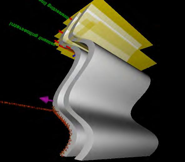
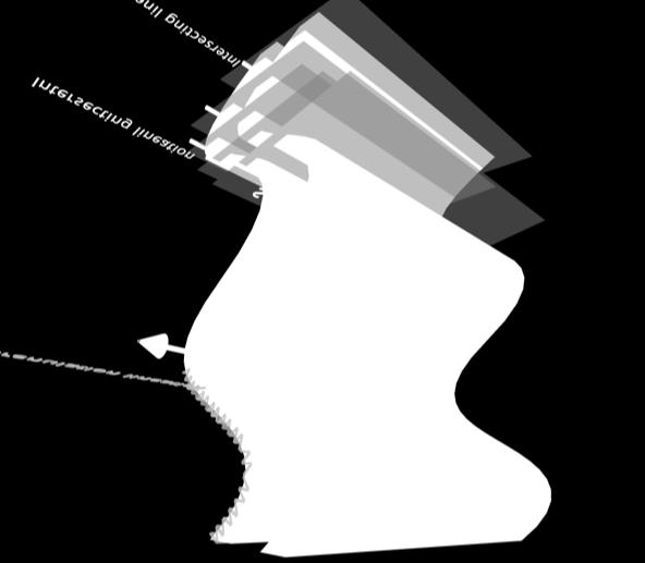
22 To extract topographic contours from a google earth terrain and import it to Sketchup: hives/2012/08/sketchup_tip_creating_ 3d_contour_li.html Interactive 5.1 Structure contours and form lines Lets assume that, on the red circle (close to the drill hole) we have measured the attitude of the top surface of a geological formation. The strike-dip and dip direction for this formation is W. Assuming that this bedding is planar, one can easily construct the intersection between this geological surface with the topographic surface. First, draw the structural contour going through the red dot. This structural contour is constructed because its azimuth (i.e., the strike of the plane) is known. 21
23 Interactive 5.2 Structure contours and form lines On a planar surface, structure contours are straight lines parallel to each others. On a curved geological surface, structure contours are curved horizontal lines. Knowing the dip and dip direction of the geological surface, a bunch of structural contours are constructed. The geological surface (here is purple) is defined by these structural contours. Intersections between the structure contours and the topographic contours lead to the formline, i.e. the intersection between the geological surface and the topography. 22
24 Interactive 5.3 Structure contours and form lines If one knows the thickness of the rock formation, or if one knows the location of the base of the formation on the topography, then the form line of the base of the rock formation can be constructed and the rock formation (here is light blue) mapped. 23

25 Interactive 5.4 Structure contours and form lines Repeating this procedure to a number of rock formations leads to the construction of a geological map. The color pattern, visible on the geological map, reflects the intersection between the the underground geology and the topography. In other terms, if the topography changes the geological map will also change. 24
26 Azimuth Clockwise angle from geographic north to a direction in an horizontal plane. Related Glossary Terms Drag related terms here Index Find Term
27 Structural contour A structural contour is an horizontal line on a geological surface such as bedding, fault, foliation etc. This concept derives from the concept of topographic contour which represents an horizontal line on the topographic surface. Related Glossary Terms Drag related terms here Index Find Term
Provided by Tasa Graphic Arts, Inc. for An Introduction to Structural Methods DVD-ROM
 Provided by Tasa Graphic Arts, Inc. for An Introduction to Structural Methods DVD-ROM http://www.tasagraphicarts.com/progstruct.html AN INTRODUCTION TO STRUCTURAL METHODS - DETAILED CONTENTS: (Navigate
LAB 1: ORIENTATION OF LINES AND PLANES
 LAB 1: ORIENTATION OF LINES AND PLANES Read the introductory section, chapter 1, pages 1-3, of the manual by Rowland et al (2007) and make sure you understand the concepts of bearing, strike, dip, trend,
lecture 8 Methods of Structural Geology This lecture Mas Rabassers de Dalt (Spain) Mas Rabassers de Dalt (Spain)
 Mas Rabassers de Dalt (Spain)") This lecture Methods of Structural Geology lecture 8 Discuss the plotting exercise on Mas Rabassers de Dalt Look at folding related to shear zones Show an example of the application of new theory: Cap
This lecture Methods of Structural Geology lecture 8 Discuss the plotting exercise on Mas Rabassers de Dalt Look at folding related to shear zones Show an example of the application of new theory: Cap
Structural Geology, GEOL 330 Fold mapping lab: Even folds get parasites Spring, 2012
 Structural Geology, GEOL 330 Name: Fold mapping lab: Even folds get parasites Spring, 2012 This exercise is meant to mimic a field experience in which you, the student, will measure beddingcleavage relationships
Team Name. Name(s) SSSS Unome Geologic Mapping Test Packet p1
 SSSS Unome Geologic Mapping Test Packet p1") Scioly Summer Study Session 2018-2019 Geologic Mapping Test Packet Written by Unome Instructions 1) This test is based on the 2016 rules for Geologic Mapping. 2) This test is out of 115 points. Questions
Scioly Summer Study Session 2018-2019 Geologic Mapping Test Packet Written by Unome Instructions 1) This test is based on the 2016 rules for Geologic Mapping. 2) This test is out of 115 points. Questions
CHAPTER Va : CONTINUOUS HETEROGENEOUS DEFORMATION
 Va-1 INTRODUCTION Heterogeneous deformation results from mechanical instabilities (folding and boudinage) within an heterogeneous material or from strain localization in an homogeneous material (shear
1. classic definition = study of deformed rocks in the upper crust
 Structural Geology I. Introduction 1. classic definition = study of deformed rocks in the upper crust deformed includes translation, rotation, and strain (change of shape) All rocks are deformed in some
MAPS AND CROSS SECTIONS (I)
") GG303 Lab 3 8/27/09 1 MAPS AND CROSS SECTIONS (I) I Main Topics A Three point problems B Rule of vees C Map interpretation and cross sections II Three point problems (see handout) A Three points define
GG303 Lab 3 8/27/09 1 MAPS AND CROSS SECTIONS (I) I Main Topics A Three point problems B Rule of vees C Map interpretation and cross sections II Three point problems (see handout) A Three points define
Using An Introduction to Structural Methods - An Interactive CD-ROM - In and Out of the Classroom
 Using An to Structural Methods - An Interactive CD-ROM - In and Out of the Classroom Tekla A. Harms, Amherst College taharms@amherst.edu H. Robert Burger, Smith College rburger@email.smith.edu TYPE OF
Materials and Methods The deformation within the process zone of a propagating fault can be modeled using an elastic approximation.
 Materials and Methods The deformation within the process zone of a propagating fault can be modeled using an elastic approximation. In the process zone, stress amplitudes are poorly determined and much
Name. GEOL.5220 Structural Geology Faults, Folds, Outcrop Patterns and Geologic Maps. I. Properties of Earth Materials
 I. Properties of Earth Materials GEOL.5220 Structural Geology Faults, Folds, Outcrop Patterns and Geologic Maps Name When rocks are subjected to differential stress the resulting build-up in strain can
Structural Geology Laboratory.
 Structural Geology Wikipedia-Structural geology is the study of the threedimensional distribution of rock units with respect to their deformational histories. The primary goal of structural geology is
A. Refer to Appendix F in back of lab manual for list of commonly used geologic map symbols
 Structural Geology Lab 2: Outcrop Patterns and Structure Contours I. Geologic Map Symbols A. Refer to Appendix F in back of lab manual for list of commonly used geologic map symbols 1. Emphasis: a. strike
Structural Geology and Geology Maps Lab
 Structural Geology and Geology Maps Lab Mesa College Geology 101 Lab Ray Rector: Instructor Structural Geology Lab Pre-Lab Resources Pre-Lab Internet Links 1) Fundamentals of Structural Geology 2) Visualizing
UNIVERSITY OF PRETORIA Department of Geology STRUCTURAL GEOLOGY -GLY 254 SEMESTER EXAM
 UNIVERSITY OF PRETORIA Department of Geology STRUCTURAL GEOLOGY -GLY 254 SEMESTER EXAM Copyright reserved 6 th June 2006 Time: 3 hours Internal examiner: Dr A.J. Bumby External examiner: Dr R. van der
Problem Set #4: Folds and Folding Stereonet Analysis Due Tuesday, Nov. 22
 Geol 360 PS #4 Name Problem Set #4: Folds and Folding Stereonet Analysis Due Tuesday, Nov. 22 Supplies: a. Data: i. Compilation of bedding attitudes at Mt Baldy; BaldyBedding.txt ii. Compilation of bedding
Part I. PRELAB SECTION To be completed before labs starts:
 Student Name: Physical Geology 101 Laboratory #13 Structural Geology II Drawing and Analyzing Folds and Faults Grade: Introduction & Purpose: Structural geology is the study of how geologic rock units
Answer sheet for question 1 Answer question 1 as soon as the sample arrives at your desk.
 EAS 233 Geologic structures. Final test. April 2012. 3 hours. Answer question 1 and 2 and three other questions. If you start more than the required number of questions, clearly delete the answers you
Chapter 15 Structures
 Chapter 15 Structures Plummer/McGeary/Carlson (c) The McGraw-Hill Companies, Inc. TECTONIC FORCES AT WORK Stress & Strain Stress Strain Compressive stress Shortening strain Tensional stress stretching
Lecture 6 Folds, Faults and Deformation Dr. Shwan Omar
 Fold: A fold is a bend or wrinkle of rock layers or foliation; folds form as a sequence of ductile deformation. Folding is the processes by which crustal forces deform an area of crust so that layers of
Chapter 10: Deformation and Mountain Building. Fig. 10.1
 Chapter 10: Deformation and Mountain Building Fig. 10.1 OBJECTIVES Describe the processes of rock deformation and compare and contrast ductile and brittle behavior in rocks. Explain how strike and dip
Stress and Strain. Stress is a force per unit area. Strain is a change in size or shape in response to stress
 Geologic Structures Geologic structures are dynamically-produced patterns or arrangements of rock or sediment that result from, and give information about, forces within the Earth Produced as rocks change
Lab 6: Plate tectonics, structural geology and geologic maps
 Geology 103 Name(s): Lab 6: Plate tectonics, structural geology and geologic maps Objective: To show the effects of plate tectonics on a large-scale set of rocks and to reconstruct the geological history
Dip-Sequence Analysis
 Chapter 9 Dip-Sequence Analysis 9.1 Introduction The three-dimensional geometry of a structure can be determined from the bedding attitudes measured in a single well bore or on a traverse through a structure.
This is OK for soil, but for rock is not. Back to the original derivation:
 * Comments on: o Effective stress law for rocks: ) total + u u z w γ w This is OK for soil, but for rock is not. Back to the original derivation: total + u ( a s ) a/a in soil as is negligible. But in
EXAMINATION PAPER. Exam in: GEO-3104 Date: Friday 27th February 2015 Time: Kl 09:00 12:00 Place: B154
 EXAMINATION PAPER Exam in: GEO-3104 Date: Friday 27th February 2015 Time: Kl 09:00 12:00 Place: B154 Approved aids: Ruler (linjal), compass (passer), protractor (vinkelmåler), calculator, ordbok (engelsk),
Crustal Deformation. (Building Earth s Surface, Part 1) Science 330 Summer Mapping geologic structures
 Science 330 Summer Mapping geologic structures") Crustal Deformation (Building Earth s Surface, Part 1) Science 330 Summer 2005 Mapping geologic structures When conducting a study of a region, a geologist identifies and describes the dominant rock structures
Crustal Deformation (Building Earth s Surface, Part 1) Science 330 Summer 2005 Mapping geologic structures When conducting a study of a region, a geologist identifies and describes the dominant rock structures
Enhanced Subsurface Interpolation by Geological Cross-Sections by SangGi Hwang, PaiChai University, Korea
 Enhanced Subsurface Interpolation by Geological Cross-Sections by SangGi Hwang, PaiChai University, Korea Abstract Subsurface geological structures, such as bedding, fault planes and ore body, are disturbed
Crustal Deformation Earth - Chapter Pearson Education, Inc.
 Crustal Deformation Earth - Chapter 10 Structural Geology Structural geologists study the architecture and processes responsible for deformation of Earth s crust. A working knowledge of rock structures
Lab 7: STRUCTURAL GEOLOGY FOLDS AND FAULTS
 Lab 7: STRUCTURAL GEOLOGY FOLDS AND FAULTS This set of labs will focus on the structures that result from deformation in earth s crust, namely folds and faults. By the end of these labs you should be able
EAS 233 Geologic Structures and Maps Winter Miscellaneous practice map exercises. 1. Fault and separation:
 Miscellaneous practice map exercises 1. Fault and separation: With respect to Map 1, what are (a) the orientation of the fault, and (b) the orientation of bedding in the units cut by the fault. (c) Mark
OCEAN/ESS 410. Lab 12. Earthquake Focal Mechanisms. You can write your answers to all be (e) on this paper.
 on this paper.") Lab 1. Earthquake Focal Mechanisms You can write your answers to all be (e) on this paper. In this class we are going to use P-wave first motions to obtain a double-couple focal mechanism for a subduction
Lab 1. Earthquake Focal Mechanisms You can write your answers to all be (e) on this paper. In this class we are going to use P-wave first motions to obtain a double-couple focal mechanism for a subduction
Structural Geology, GEOL 330 Spring 2012
 Developing the Magic Eye for folds This lab exercise is designed to get you thinking about the chronology of structural processes and and the resultant map patterns in areas with flat topography. You may
CRUSTAL DEFORMATION. Chapter 10
 CRUSTAL DEFORMATION and dgeologic Structures t Chapter 10 Deformation Df Deformation involves: Stress the amount of force applied to a given area. Types of Stress: Confining Stress stress applied equally
GY403 Structural Geology. Tectonite Fabrics
 GY403 Structural Geology Tectonite Fabrics Tectonite Fabric A tectonite is a rock that possess a penetrative fabric consisting of cleavage, foliation and/or lineation Tectonite fabrics are associated with
SSSS Unome Geologic Mapping Answer Key p1
 Scioly Summer Study Session 2018-2019 Geologic Mapping Answer Key Written by Unome Instructions Because this test is written for SSSS, the answer key includes explanations for most questions. It is also
Staple this part to part one of lab 6 and turn in. Lab 6, part two: Structural geology (analysis)
") Geology 101 Staple this part to part one of lab 6 and turn in Lab 6, part two: Structural geology (analysis) Recall that the objective of this lab is to describe the geologic structures of Cougar Mountain
Geology 101 Staple this part to part one of lab 6 and turn in Lab 6, part two: Structural geology (analysis) Recall that the objective of this lab is to describe the geologic structures of Cougar Mountain
PLANE AND ATTITUDE OF STRATA
 2307216 Field Methods in Geology I PLANE AND ATTITUDE OF STRATA ผ ช วยศาสตราจารย ดร.ว ช ย จ ฑะโกส ทธ กานนท ภาคว ชาธรณ ว ทยา คณะว ทยาศาสตร จ ฬาลงกรณ มหาว ทยาล ย vichaic@yahoo.com Outline Basic knowledge
UNIT 10 MOUNTAIN BUILDING AND EVOLUTION OF CONTINENTS
 UNIT 10 MOUNTAIN BUILDING AND EVOLUTION OF CONTINENTS ROCK DEFORMATION Tectonic forces exert different types of stress on rocks in different geologic environments. STRESS The first, called confining stress
GRAPHICAL PRESENTATION AND STATISTICAL ORIENTATION OF STRUCTURAL DATA PRESENTED WITH STEREOGRAPHIC PROJECTIONS FOR 3-D ANALYSES.
 GRAPHICAL PRESENTATION AND STATISTICAL ORIENTATION OF STRUCTURAL DATA PRESENTED WITH STEREOGRAPHIC PROJECTIONS FOR 3-D ANALYSES. COMMONLY USED PLOTTING AND CONTOURING TOOLS CAN BE DOWNLOADED FOR VARIOUS
Evaluation of Structural Geology of Jabal Omar
 International Journal of Engineering Research and Development e-issn: 2278-067X, p-issn: 2278-800X, www.ijerd.com Volume 11, Issue 01 (January 2015), PP.67-72 Dafalla Siddig Dafalla * and Ibrahim Abdel
Is the Troodos ophiolite (Cyprus) a complete, transform. fault bounded Neotethyan ridge segment?
 a complete, transform. fault bounded Neotethyan ridge segment?") GSA Data Repository DR1 Is the Troodos ophiolite (Cyprus) a complete, transform fault bounded Neotethyan ridge segment? Antony Morris and Marco Maffione Data Repository methods 1.1. Paleomagnetic analysis
GSA Data Repository DR1 Is the Troodos ophiolite (Cyprus) a complete, transform fault bounded Neotethyan ridge segment? Antony Morris and Marco Maffione Data Repository methods 1.1. Paleomagnetic analysis
Lecture Outline Friday March 2 thru Wednesday March 7, 2018
 Lecture Outline Friday March 2 thru Wednesday March 7, 2018 Questions? Lecture Exam Friday March 9, 2018 Same time, Same room Bring Pencils and WSU ID 50 question Multiple Choice, Computer Graded Interlude
Geo 303 Lab 6 9/8/09 1 LAB 6 - ROTATIONS
 Geo 303 Lab 6 9/8/09 1 LAB 6 - ROTATIONS Exercise 1: Apparent dip problem (28 points total) 1a) An apparent dip of 52 to the southwest is measured for a bedding plane in a vertical cross section that strikes
Crags, Cracks, and Crumples: Crustal Deformation and Mountain Building
 Crags, Cracks, and Crumples: Crustal Deformation and Mountain Building Updated by: Rick Oches, Professor of Geology & Environmental Sciences Bentley University Waltham, Massachusetts Based on slides prepared
Structural Geology Lab. The Objectives are to gain experience
 Geology 2 Structural Geology Lab The Objectives are to gain experience 1. Drawing cross sections from information given on geologic maps. 2. Recognizing folds and naming their parts on stereoscopic air
Lecture 9 faults, folds and mountain building
 Lecture 9 faults, folds and mountain building Rock deformation Deformation = all changes in size, shape, orientation, or position of a rock mass Structural geology is the study of rock deformation Deformation
Preface and Overview. Folded strata in the mountains of Italy (ca AD), Leonardo da Vinci
, Leonardo da Vinci") Preface and Overview Folded strata in the mountains of Italy (ca. 1500 AD), Leonardo da Vinci Models of Mountain Building and Associated Deformation as represented by G.P. Scrope Deformation Feature: Scales
Preface and Overview Folded strata in the mountains of Italy (ca. 1500 AD), Leonardo da Vinci Models of Mountain Building and Associated Deformation as represented by G.P. Scrope Deformation Feature: Scales
GG303 Lab 5 10/4/17 1
 GG303 Lab 5 10/4/17 1 Lab 5 Spherical Projections Use a separate piece of paper for each exercise, and include printouts of your Matlab work. 103 pts for Ex. 1-4; 124 points for Ex. 1-5. Exercise 1: Plots
both an analytical approach and the pole method, determine: (a) the direction of the
 the direction of the") Quantitative Problems Problem 4-3 Figure 4-45 shows the state of stress at a point within a soil deposit. Using both an analytical approach and the pole method, determine: (a) the direction of the principal
Quantitative Problems Problem 4-3 Figure 4-45 shows the state of stress at a point within a soil deposit. Using both an analytical approach and the pole method, determine: (a) the direction of the principal
Geology for Engineers Rock Mechanics and Deformation of Earth Materials
 89.325 Geology for Engineers Rock Mechanics and Deformation of Earth Materials Why do rocks break? Rock mechanics experiments a first order understanding. Faults and Fractures Triaxial load machine. a)
STRUCTURAL ANALYSIS. Structural analysis jpb, 2017
 STRUCTURAL ANALYSIS 269 Structural geology uses micro- and meso-scale structures found in the rocks to elaborate tools and methods enabling to identify structures too large to be directly observed, although
Deformation of Rocks. Orientation of Deformed Rocks
 Deformation of Rocks Folds and faults are geologic structures caused by deformation. Structural geology is the study of the deformation of rocks and its effects. Fig. 7.1 Orientation of Deformed Rocks
6. 地質圖 6.1 岩層於地形圖上的分布 6.2 地質剖面圖 6.3 地質圖判識 地調所五萬分之一地質圖台中圖幅
 6. 地質圖 6.1 岩層於地形圖上的分布 6.2 地質剖面圖 6.3 地質圖判識 A geological shows how geological features (rock units, faults, etc.) are distributed across a region. It is a twodimensional representation of part of the Earth
Structural Geology (GE 231) Syllabus Fall, 2007
 Syllabus Fall, 2007") 1. Instructor Walter A. Sullivan (Bill) Office: Mudd 215 Office hours: Open-door policy Office phone: 859-5803 E-mail: wasulliv@colby.edu 2. Texts and required materials Structural Geology (GE 231) Syllabus
1. Instructor Walter A. Sullivan (Bill) Office: Mudd 215 Office hours: Open-door policy Office phone: 859-5803 E-mail: wasulliv@colby.edu 2. Texts and required materials Structural Geology (GE 231) Syllabus
What Causes Rock to Deform?
 Crustal Deformation Earth, Chapter 10 Chapter 10 Crustal Deformation What Causes Rock to Deform? Deformation is a general term that refers to all changes in the shape or position of a rock body in response
Geologic Mapping Invitational Trial Event
 Geologic Mapping Invitational Trial Event A TEAM OF UP TO: 2 Team Name AVAILABLE TIME: 50 min Required Materials: Each team MUST have a protractor, ruler, non-programmable calculator, colored pencils,
Study the architecture and processes responsible for deformation of Earth s crust. Folding and Faulting
 Crustal Deformation AKA Structural geology (adapted from Brunkel, 2012) Study the architecture and processes responsible for deformation of Earth s crust. Folding and Faulting How Rocks Deform: 4 Controls
Faults, folds and mountain building
 Faults, folds and mountain building Mountain belts Deformation Orogens (Oro = Greek all changes for mountain, in size, shape, genesis orientation, = Greek for or formation) position of a rock mass Structural
Chapter 3 SECTION 1 OBJECTIVES
 Chapter 3 SECTION 1 OBJECTIVES Distinguish between latitude and longitude and locate coordinates on maps. Explain how latitude and longitude can be used to locate places on Earth s surface. Explain the
Structural Geology Lab. The Objectives are to gain experience
 Geology 2 Structural Geology Lab The Objectives are to gain experience 1. Drawing cross sections from information given on geologic maps. 2. Recognizing folds and naming their parts on stereoscopic air
Distortion Effects of Faults on Gravity Worm Strings Robin O Leary
 Distortion Effects of Faults on Gravity Worm Strings Robin O Leary Problem Can upward continued gravity anomaly worm strings be used as a tool to determine the dip direction of an offsetting structure
EARTHQUAKE LOCATIONS INDICATE PLATE BOUNDARIES EARTHQUAKE MECHANISMS SHOW MOTION
 6-1 6: EARTHQUAKE FOCAL MECHANISMS AND PLATE MOTIONS Hebgen Lake, Montana 1959 Ms 7.5 1 Stein & Wysession, 2003 Owens Valley, California 1872 Mw ~7.5 EARTHQUAKE LOCATIONS INDICATE PLATE BOUNDARIES EARTHQUAKE
Fold Analysis Challenge
 GETTING STARTED: The is designed to help geology students attain competency in basic structural analysis of folds using Google Earth. There are two versions, online and desktop. For the online version,
BEYOND TRAVELTIMES AND EARTHQUAKE LOCATION What else can seismograms tell us about the nature of earthquakes on faults?
 BEYOND TRAVELTIMES AND EARTHQUAKE LOCATION What else can seismograms tell us about the nature of earthquakes on faults? What are some of the key parameters which we describe faults? GEOMETRICAL PROPERTIES
Deformation and Strain
 Deformation and Strain Processes in Structural Geology & Tectonics Ben van der Pluijm WW Norton+Authors, unless noted otherwise 2/13/2017 15:13 We Discuss Deformation and Strain Deformation Components
You must take the exam in the lecture section for which you are registered. Any exceptions must be cleared with the instructor in advance.
 Geo 101, Fall 2000 Review Questions for Final Exam GEOLOGIC TIME AND FOLDING AND FAULTING THE FINAL EXAM FOR MWF CLASS WILL BE TUESDAY 1400 THE FINAL EXAM FOR TR CLASS WILL BE FRIDAY 930 These questions
shear zones Ductile shear zones can develop as a results of shearing (simple shear strain) or "squeezing" (pure shear strain).
 or squeezing (pure shear strain).") shear zones Ductile shear zones can develop as a results of shearing (simple shear strain) or "squeezing" (pure shear strain). Shear Zones Mylonite, or mylonitic zone is the central part of the shear zone
shear zones Ductile shear zones can develop as a results of shearing (simple shear strain) or "squeezing" (pure shear strain). Shear Zones Mylonite, or mylonitic zone is the central part of the shear zone
The University of Jordan. Accreditation & Quality Assurance Center. Course Name: Structural Geology COURSE Syllabus
 The University of Jordan Accreditation & Quality Assurance Center COURSE Syllabus Course Name: Structural Geology 0305341 1 Course title Structural Geology 2 Course number 0305341 3 Credit hours (theory,
Kinematic Analysis Underground Wedges
 EOSC433: Geotechnical Engineering Practice & Design Supplementary Notes: Wedge Volume Calculation 1 of 16 Erik Eberhardt UBC Geological Engineering EOSC 433 Kinematic Analysis Underground Wedges The minimum
Map projections. Rüdiger Gens
 Rüdiger Gens Coordinate systems Geographic coordinates f a: semi-major axis b: semi-minor axis Geographic latitude b Geodetic latitude a f: flattening = (a-b)/a Expresses as a fraction 1/f = about 300
Springshed Springshed Management Training Curriculum
 Springshed Springshed Management Training Curriculum Management Training Curriculum Draft Version 2 January 2016 The Springs Initiative 2016 The Springs Initiative SESSION TITLE: Section Mapping SECTION:
EPS 50 Lab 6: Maps Topography, geologic structures and relative age determinations
 Name: EPS 50 Lab 6: Maps Topography, geologic structures and relative age determinations Introduction: Maps are some of the most interesting and informative printed documents available. We are familiar
UNDERSTANDING GEOLOGIC M APS
 Name: Lab Section: work in groups, but each person turns in his/her own GEOSCIENCE 001 L AB UNDERSTANDING GEOLOGIC M APS Geologic maps are colorful and even beautiful, but they also contain an amazing
Critical Borehole Orientations Rock Mechanics Aspects
 Critical Borehole Orientations Rock Mechanics Aspects By R. BRAUN* Abstract This article discusses rock mechanics aspects of the relationship between borehole stability and borehole orientation. Two kinds
Lecture 9. Folds and Folding. Earth Structure (2 nd Edition), 2004 W.W. Norton & Co, New York Slide show by Ben van der Pluijm
, 2004 W.W. Norton & Co, New York Slide show by Ben van der Pluijm") Lecture 9 Folds and Folding Earth Structure (2 nd Edition), 2004 W.W. Norton & Co, New York Slide show by Ben van der Pluijm WW Norton; unless noted otherwise Fold Classification Maryland Appalachians
Lecture 9 Folds and Folding Earth Structure (2 nd Edition), 2004 W.W. Norton & Co, New York Slide show by Ben van der Pluijm WW Norton; unless noted otherwise Fold Classification Maryland Appalachians
GRAPHICAL PRESENTATION AND STATISTICAL ORIENTATION OF STRUCTURAL DATA PRESENTED WITH STEREOGRAPHIC PROJECTIONS FOR 3-D ANALYSES.
 GRAPHICAL PRESENTATION AND STATISTICAL ORIENTATION OF STRUCTURAL DATA PRESENTED WITH STEREOGRAPHIC PROJECTIONS FOR 3-D ANALYSES. COMMONLY USED PLOTTING AND CONTOURING TOOLS CAN BE DOWNLOADED FOR VARIOUS
GMT TECHNICAL REFERENCE & COOKBOOK Azimuthal Projections Lambert Azimuthal Equal-Area ( Ja or JA)
") GMT TECHNICAL REFERENCE & COOKBOOK 5 7 5.3 Azimuthal Projections 5.3.1 Lambert Azimuthal Equal-Area ( Ja or JA) This projection was developed by Lambert in 1772 and is typically used for mapping large
GMT TECHNICAL REFERENCE & COOKBOOK 5 7 5.3 Azimuthal Projections 5.3.1 Lambert Azimuthal Equal-Area ( Ja or JA) This projection was developed by Lambert in 1772 and is typically used for mapping large
Fold Analysis Challenge Sheep Mountain, Wyoming
 Fold Analysis Challenge Sheep Mountain, Wyoming Introduction The Bighorn Basin area of Wyoming is well known for interesting and well- developed fold structures that also have economic significance - well
Topographic Maps and Landforms Geology Lab
 Topographic Maps and Landforms Geology Lab Ray Rector: Instructor Today s Lab Activities 1) Discussion of Last Week s Lab 2) Lecture on Topo Maps and Elevation Contours 3) Construct Topographic Maps and
PROBLEM SET #X. 2) Draw a cross section from A-A using the topographic profile provided on page 3.
 Draw a cross section from A-A using the topographic profile provided on page 3.") PROBLEM SET #X PART A: The geologic map on page 3 is from an area consisting of faulted Miocene sedimentary rocks. There are two major faults exposed here: the Rattlesnake fault and the Jackrabbit fault.
PROBLEM SET #X PART A: The geologic map on page 3 is from an area consisting of faulted Miocene sedimentary rocks. There are two major faults exposed here: the Rattlesnake fault and the Jackrabbit fault.
Lab 8: Folds and their map patterns
 Lab 8: Fols an their map patterns Fall 2005 1 Fols are one of the most common tectonic structures evelope in eforme rocks. They form in rocks containing planar features such as seimentary being, lithologic
Structural Analysis of Rocks and Regions 2017 Maps and cross-sections
 Structural Analysis of Rocks and Regions 2017 Maps and cross-sections The practicals in SARR will introduce you to (or remind you of) the tools and skills that are typically used to reconstruct and quantify
Earthquakes and Seismotectonics Chapter 5
 Earthquakes and Seismotectonics Chapter 5 What Creates Earthquakes? The term Earthquake is ambiguous: Applies to general shaking of the ground and to the source of the shaking We will talk about both,
Geomorphology Final Exam Study Guide
 Geomorphology Final Exam Study Guide Geologic Structures STRUCTURAL GEOLOGY concerned with shapes, arrangement, interrelationships of bedrock units & endogenic (within) forces that cause them. Tectonic
Faults. Strike-slip fault. Normal fault. Thrust fault
 Faults Strike-slip fault Normal fault Thrust fault Fault any surface or narrow zone with visible shear displacement along the zone Normal fault Strike-slip fault Reverse fault Thrust fault
Brittle Deformation. Earth Structure (2 nd Edition), 2004 W.W. Norton & Co, New York Slide show by Ben van der Pluijm
, 2004 W.W. Norton & Co, New York Slide show by Ben van der Pluijm") Lecture 6 Brittle Deformation Earth Structure (2 nd Edition), 2004 W.W. Norton & Co, New York Slide show by Ben van der Pluijm WW Norton, unless noted otherwise Brittle deformation EarthStructure (2 nd
Lecture 6 Brittle Deformation Earth Structure (2 nd Edition), 2004 W.W. Norton & Co, New York Slide show by Ben van der Pluijm WW Norton, unless noted otherwise Brittle deformation EarthStructure (2 nd
Geological mapwork from scratch 2: valley with simple geology Draw your own cross sections and 3D geological model
 Geological mapwork scratch 2: valley with simple geology Draw your own cross sections and 3D geological model A valley with a stream looks like this: Modified the Geograph project collection. Copyright
GEOL 321 Structural Geology and Tectonics
 GEOL 321 Structural Geology and Tectonics Geology 321 Structure and Tectonics will be given in Spring 2017. The course provides a general coverage of the structures produced by brittle and ductile rock
Instituto De Ingenieros De Minas Del Peru
 The Continuity Challenge Dr. Wayne Barnett The Interpretation! Great geological continuity? Huge potential? The Reality Not what it might seem... Not what it might seem... Presentation Objective Highlight
GEOL 3700 STRUCTURE AND TECTONICS LABORATORY EXERCISE 3
 GEOL 3700 STRUCTURE AND TECTONICS LABORATORY EXERCISE 3 Goals: 1. Improve your map-reading and map-making skills. 2. Learn to generate and interpret structure contour maps. 3. Learn to generate and interpret
Over six hundred 2.54 cm cores were collected at 18 sites in the Portilla Formation and
 Weil et al., page 1 DATA REPOSITORY 2001112 SAMPLING AND EXPERIMENTAL METHODS Over six hundred 2.54 cm cores were collected at 18 sites in the Portilla Formation and 41 sites in the Santa Lucia Formation
Rock slope rock wedge stability
 Engineering manual No. 28 Updated: 02/2018 Rock slope rock wedge stability Program: Rock stability File: Demo_manual_28.gsk The aim of the chapter of this engineering manual is to explain a rock slope
Horizontal Stress. US Stress Regimes: In the eastern United States:
 Horizontal Stress 1. In the last 30 years, horizontal stress has been recognized as a major component of ground control problems. 2. In general, the horizontal stresses found in coal mines are caused by
In this lab, we will study and analyze geologic maps from a few regions, including the Grand Canyon, western Wyoming, and coastal California.
 Name: Lab Section: work in groups, but each person turns in his/her own GEOSCIENCE 001 LAB UNDERSTANDING GEOLOGIC MAPS Geologic maps are colorful and even beautiful, but they also contain an amazing amount
Geological mapwork from scratch 3: valley with dipping geology Draw your own cross sections and 3D geological model
 Geological mapwork from scratch 3: valley with dipping geology Draw your own cross sections and 3D geological model A valley with a river looks like this: The straight glen of the Allt Mhuic from its headwaters
Vein arrays and their relationship to transpression during fold development in the Culm Basin, central south-west England
 356 Read at the Annual Conference of the Ussher Society, January 1991 Vein arrays and their relationship to transpression during fold development in the Culm Basin, central south-west England R.R. JACKSON
N30 E-45 SE S25 E-10 SW N85 W-80 NE
 Geologic aps and tructures Name Geology 100 Harbor section Read h. 7 before you begin. The objectives of this lab are for you to learn the basic geologic structures in 3- and to develop some facility in
Exercise: concepts from chapter 8
 Reading: Fundamentals of Structural Geology, Ch 8 1) The following exercises explore elementary concepts associated with a linear elastic material that is isotropic and homogeneous with respect to elastic
GIS-BASED KINEMATIC SLOPE STABILITY ANALYSIS
 GIS-BASED KINEMATIC SLOPE STABILITY ANALYSIS Tim Mote, Derek Morley, Timothy Keuscher, and Todd Crampton Geomatrix Consultants, Inc., 2101 Webster St., 12 th Floor, Oakland, CA 94612 www.geomatrix.com