ABSTRACT. Tianhuan Dai, Master of Science, Assistant Professor, Dazhi Jiang, Department of Geology
|
|
|
- Laurel Mitchell
- 5 years ago
- Views:
Transcription
1 ABSTRACT Title of Thesis: KINEMATICS AND DEFORMATION HISTORY OF THE CROSS LAKE GREENSTONE BELT Tianhuan Dai, Master of Science, 2004 Thesis Directed By: Assistant Professor, Dazhi Jiang, Department of Geology Greenstone belts are a common feature of Archean terrains. However, the tectonic environment for Archean earth remains in hot debate: did vertical or horizontal crustal movement dominate the Archean Eon? Small-scale structural analysis is applied to a late Archean greenstone belt in the Superior Province of the Canadian Shield in order to test the two end member hypotheses. Detailed structural analysis reveals that the Cross Lake greenstone belt has undergone three major events of deformation. The early event of ESE-WNW convergence and crustal thickening initiated folding and produced northeast-trending shear zones. The configuration of the northwestern Cross Lake area is largely due to this event. This was followed by the juxtaposition of the Nelson River - Pipestone Lake high-strain zone. The last event was the juxtaposition of the Eves Rapids Complex with the development of a major northeast-trending fault, which overprints all previous deformation. The strain geometry and structural features suggest that the first event of crustal thickening likely involved vertical tectonics induced by gravitational instability rather than transpression.
2 KINEMATICS AND DEFORMATION HISTORY OF THE CROSS LAKE GREENSTONE BELT By Tianhuan Dai Thesis submitted to the Faculty of the Graduate School of the University of Maryland, College Park, in partial fulfillment of the requirements for the degree of Master of Science 2004 Advisory Committee: Assistant Professor Dazhi Jiang, Chair Professor Michael Brown Professor Philip Candela
3 Copyright by Tianhuan Dai 2004
4 Dedication To my mother Yun and my father Qiang. ii
5 Acknowledgements It has been a very unique journey since I started my graduate study at University of Maryland: I experienced the initial cultural shock and excitement when I first came to this country; I went through a long hard period of confusion and depression when I was about to finish my research; and I was able to finally pick myself back up to complete this thesis. Along the way, so many people have helped me. They did not give up on me even when I gave up on myself. Without them, I would not be able to make it. I feel so lucky and grateful, and I would like to thank all these people for their support all along. First and foremost, I would like to thank my advisor, Dazhi Jiang. Dr. Jiang is not only a superb teacher who has advised me on my schoolwork and research, but also a patient mentor who has guided me how to take my responsibilities as an adult and how to make my best effort to achieve my goals. Dr. Jiang had high expectation of me when I became his student. However, I may have disappointed him many times in the past four and half years. Yet, he would patiently encourage me and search solutions in my problems every time. Dr. Jiang has spent tremendous energy and time on me ever since I came to this country. In particular, he helped to turn a pile of paper with scattered pieces of information into a coherent thesis as you see today. Secondly, I would like to thank my committee members Dr. Michael Brown and Dr. Philip Candela. I have benefited much from their classes and discussions with them. Dr. Brown recommended me some of the newest publications on topics related to my research. Dr. Candela is a witty professor with incredible knowledge of a broad iii
6 variety of things. Both have offered me valuable advices on how to complete my project. The rest of the Department of Geology has also offered great help. Dr. Richard Walker had to sign paperwork many times for me due various changes and problems I have had over the years. Conversations and interactions with other faculty members and fellow graduate students have also been enjoyable and beneficial. The department secretaries have offered continuous assistance since the first day I started here. Especially, Jeanne Martin helped me with paperwork and procedures necessary to complete my graduate program. A very special thank-you goes to Tim Corkery and Manitoba Geological Survey of Canada. Manitoba Geological Survey generously provided funding and equipments for the fieldwork part of my research. It was Tim Corkery who first introduced me to the geology of the Cross Lake greenstone belt. He showed great enthusiasm towards the project, and offered the most extensive help in the field for three summers. He is not only a professional field geologist to work with, but also a warmest friend from whom I received kind hospitality and wise advice. Neill Brandson, who diligently and thoroughly offered logistical field support, is one of the kindest persons I have ever met. Without him, the fieldwork would have not been completed smoothly. Jerine Thackery, Patrick Truman, and Daniel Martin, all geology-major students from the University of Manitoba are sincerely thanked for their tireless assistance in the field. Last, I thank my parents and my best friends Dianin, Caobin, and Sanath for their support and encouragement. iv
7 Table of Contents Dedication... ii Acknowledgements...iii Table of Contents... v List of Figures... vii Chapter 1: General Introduction and an Outline of the Thesis Purpose of the Study Initiation and Process of the Project Outline of the Thesis... 7 Chapter 2: Contrasting Strain Geometries and Deformation Kinematics Expected in Obliquely - Convergent Plate Boundary Regions and in Vertical Tectonic Regimes Obliquely-Convergent Plate Boundaries: Transpression Vertical Tectonics CHAPTER 3: General Statement and Geological Settings of the Cross Lake Greenstone Belt General Statement of Archean Greenstone Belt and the Superior Province Geological Setting of the Cross Lake Greenstone Belt The Pipestone Lake Group The Gunpoint Group The Cross Lake Group Early Intrusive Rocks Achean Late Intrusive Rocks Proterozoic Rocks CHAPTER 4: Structural Analysis of the Cross Lake Greenstone Belt General Statement Structural Analysis of Domain I D 1 Deformation D 2 Deformation Structural Analysis of Domain II D 1 Deformation D 2 Deformation NE-trending Shear Zones Structural Analysis of the NR-PSL High-Strain Zone D 1 Deformation D 2 Deformation D 3 Deformation The Northern Cross Lake Thrust Chapter 5: Kinematic Interpretation ESE-WNW Convergence and Accompanying Crustal Thickening Interpreting the Structural Data The Shape of the Strain Ellipsoid Constructed from Clast Fabric Tectonic Environment Juxtaposition of the NR-PSL High-Strain zone with Domains I and II v
8 5.3 The Juxtaposition of the Eves Rapids Complex the Development of the NCLBT Discussion: Transpression or Gravity Induced Instability The Relationship between the CLGB and Regional Tectonism Main Conclusions vi
9 List of Figures Fig 1.1: A simplified geological map of the northwestern Superior Province 3 Fig 1.2: Base map of the Cross Lake area 5 Fig 2.1: Strain geometry predicted by transpression 11 Fig 2.2: Flinn diagram of transpression zones 12 Fig 2.3: Strain geometry predicted by vertical tectonics 14 Fig 3.1: Geological map of the Cross Lake greenstone belt 19 Fig 3.2: The Pipestone Lake Group 23 Fig 3.3: The Gunpoint Group 25 Fig 3.4: The Cross Lake Group conglomerates 27 Fig 3.5: The Cross Lake Group sandstones 28 Fig 3.6: Stratigraphy of the Cross Lake greenstone belt 29 Fig 3.7: The Pipestone Lake Group anorthorsite 31 Fig 3.8: Pegmatite dykes 33 Fig 4.1: Geological map of the northwestern Cross Lake area 36 Fig 4.2: Cross-bedding preserved in the Cross Lake Group sandstone 37 Fig 4.3: Equal-area lower hemisphere plot of the structural data of Domain I 38 Fig 4.4: L 1 lineation of Domain I 40 Fig 4.5: Schematic cross-section A-A in Domain I 42 Fig 4.6: Cross-bedding preserved in the Cross Lake Group sandstone 44 Fig 4.7: Equal-area lower hemisphere plot of the structural data of Domain II 45 Fig 4.8: S 0 -S 1 relationship in the Cross Lake Group cross-bedded pebbly sandstone 46 vii
10 Fig 4.9: L 1 lineation of Domain II 47 Fig 4.10: Sheath fold 48 Fig 4.11: Boudinaged cal-silicate layer 49 Fig 4.12: Crenulation cleavage 51 Fig 4.13: Equal-area lower hemisphere plot of the structural data of MCL shear zone 53 Fig 4.14: Geological map of the NR-PSL high-strain zone 56 Fig 4.15: Equal-area lower hemisphere plot of the planar structural data of the NR- PSL high-strain zone 57 Fig 4.16: Equal-area lower hemisphere plot of the linear structural data of the NR- PSL high-strain zone 58 Fig 4.17: F 1 folds of the NR-PSL high-strain zone 59 Fig 4.18: Boundins preserved in the Pipestone Lake Group basalt 60 Fig 4.19: Drag folds 62 Fig 4.20: Schematic cross-sections of the NR-PSL high-strain zone 63 Fig 5.1: Equal-area lower hemisphere plot of the structural data of Domain II 69 Fig 5.2: Block diagrams illustrating ESE-WNW convergence and accompanying crustal shortening 70 Fig 5.3: Orientated photos of the Gunpoint Group conglomerate used in the determination of the strain ellipsoid 72 Fig 5.4: Flinn diagram showing the shape of the strain ellipsoid 74 Fig 5.5: Kinematic evolution of the Cross Lake greenstone belt 76 viii
11 Fig 5.6: Equal-area lower hemisphere plot of the structural data of the NR-PSL highstrain zone 78 ix
12 Chapter 1: General Introduction and an Outline of the Thesis 1.1 Purpose of the Study It is now generally accepted that plate tectonics has been in operation at least since Proterozoic (e.g., Wyllie, 1971). There are two opinions for the tectonic regime in the Archean. One holds that there is no fundamental difference in the tectonic regime between the Archean and post-archean, except that plates in the Archean might have been smaller, thinner, and more numerous (e.g., Kröner, 1991; Myers et al., 1994). Another opinion holds that vertical tectonics driven by density inverse dominated the Archean Eon (e.g., Goodwin, 1981; Choukroune et al., 1995). These two hypotheses have different consequences on the kinematics of crustal deformation and should have resulted in different styles and patterns of small-scale structures in Archean terrains. If in the Archean the deformation was driven by plate tectonics, small-scale structures in Archean terrains should, on an orogen scale, reflect dominantly horizontal crustal movement. Strain geometry and deformation kinematics in various types of plate boundaries including extension/shortening, wrenching, and transtension/transpression have been well studied by many authors (e.g., Ramsay and Graham, 1970; Harland, 1971; Lister and Williams, 1979; Sanderson and Marchini, 1984; Dewey, 1998; Jiang et al., 2001; among many others). This body of research provides the basis for geologists to identify ancient plate boundaries from the study of small-scale structures. On the other hand, if the deformation during the Archean was dominated by vertical crustal movement driven by gravitational instability, the associated strain geometry and deformation 1
13 kinematics are expected to be quite different from those of the plate tectonic environment. Strain geometry and deformation kinematics resulted from vertical crustal movement such as diapirism have also been studied by different authors (e.g., Anhaeusser, 1969; Gorman et al., 1978; Marecshal and West, 1980; Dixon and Summers, 1983). The purpose of the thesis is to apply small-scale structural analysis (e.g., Lin et al., 1996) to a late Archean greenstone belt in the Superior Province of the Canadian Shield to test these two end member hypotheses. The methodology is similar to Lin et al. (1996) and Lin and Jiang (2001). 1.2 Initiation and Process of the Project The study area is located in the Cross Lake Greenstone Belt (CLGB) in Manitoba, which is in the southwest corner of the northwestern Superior Province (Fig 1.1). This project is a joint one between the University of Maryland and the Manitoba Geological Survey. The Manitoba Geological Survey provided funding for the fieldwork part. The fieldwork of the project was conducted in three summers ( ). Field structural mapping covered the area indicated in Fig 1.2. Outcrops are abundant and of excellent to reasonable quality along lake shorelines. Large-scale (1:25000) structural mapping was conducted on the basis of previous preliminary lithological maps (Corkery et al., 1987a, b). In addition to confirming and revising the lithological units, emphasis was placed on collecting structural data. Foliation and lineation, and various outcrop-scale structures and kinematic indicators such as asymmetric folds and shear bands were measured in the field. 2
.")
14 Fig 1.1: A simplified geological map of the northwestern Superior Province showing location of the study area and major geological domains in northwestern Superior Province. The Cross Lake greenstone belt is indicated and the box marked Fig 1.2 is the study area (modified from Corkery et al., 1992). The mapping started from the region along Nelson River, later named the Nelson River Pipestone Lake (NR-PSL) high-strain zone (Fig 1.2), in the summer of 2001, and was expanded to outside of the NR-PSL high-strain zone in the following two summers. In the summer of 2002 a structural study in the northwestern Cross Lake area was conducted. The study area extends from the north-shore of the Cross Island to Eves Rapids about 6 kilometers north and northwestward. The work of 2002 focused on the widespread Cross Lake Group, whereas the work of 2003 was 3
15 concentrated on the Gunpoint Group and the Pipestone Lake Group in the northwestern Cross Lake area. Field structural data were processed in the laboratory. Based on structural data, the whole mapped area is divided into three structural domains, for each of which the structural geometry is established and the kinematic evolution is interpreted. The kinematic relationships among the domains are then constructed. This leads to a tectonic synthesis of the greenstone belt as a whole. 4

16 Fig 1.2a: Base map of the Cross Lake area showing place names referred to in the thesis. The two rectangle areas are detailed fieldwork areas. 5


17 Fig 1.2b: Base map of the Cross Lake area showing station numbers of fieldwork. 6
18 1. 3 Outline of the Thesis This thesis consists of five main body chapters. Chapter 2 summarizes the predictions on strain geometry of the two tectonic regimes (plate tectonics and vertical tectonics). This forms the basis for using small-scale structural analysis to discriminate the two hypotheses. Chapter 3 describes the Archean greenstone belts in the Superior Province in general and Chapter 4 describes the Cross Lake Greenstone Belt (CLGB) in particular. Chapter 3 gives the regional tectonic settings and stratigraphy of the CLGB. Emphasis is on the description of the main lithological units, their distribution, ages, and contact relationships. Chapter 4 presents a detailed structural analysis of the CLGB. In Chapter 5, structural interpretation is given for the CLGB. A discussion at the end of the chapter focuses on testing the two hypotheses based on comparing strain geometry and kinematics of the CLGB and the predictions of the two tectonic hypotheses. Following the discussion, main conclusions of the project are summarized. 7
19 Chapter 2: Contrasting Strain Geometries and Deformation Kinematics Expected in Obliquely - Convergent Plate Boundary Regions and in Vertical Tectonic Regimes Plate tectonic leads to predominantly horizontal crustal movement whereas vertical tectonics driven by density inverse is characterized by vertical crustal motion. The two different crustal motions produce distinctively different strain geometries and deformation kinematics. 2.1 Obliquely-Convergent Plate Boundaries: Transpression Deformation at plate boundaries has been well studied. From a kinematic point of view, a plate boundary can be under extension (such as in divergent plate boundaries), shortening, shearing (wrenching), or a combination of shearing and extension (transtension), or a combination of shearing and shortening (transpression) (Harland, 1971). If deformation in Archean greenstone belts was due to plate-like crustal motion, then the structures most likely developed in the kinematic spectrum from pure shortening to shearing regime, i.e. transpressional environment. Transpression refers to oblique convergence between the boundaries (Harland, 1971) and its resulting deformation (Sanderson and Marchini, 1984). Theoretical modeling works have been done by many authors, and a unified model was proposed by Jiang and Williams (1998). Ramsay and Graham (1970) and Ramsay (1980) proposed simple shear model. Ramberg (1975) considered constant-volume steady-state deformation as various combinations of pure and simple shear. These are the earliest studies of the strain geometry and kinematics of high-strain zones. Sanderson and Marchini (1984) first proposed a three-dimensional model where a vertical high-strain 8
20 zone has strike-slip and zone thins (transpression) or thickens (transtension) in response to zone-normal flattening or extension. Fossen and Tikoff (1993) and Tikoff and Fossen (1994) reformulated Sanderson and Marchini s model following Ramberg s approach, and concluded that, for a vertical transpressional high-strain zone, the maximum principal finite strain axis will be either horizontal or vertical. Passchier (1998) summarized all monoclinic models. However, monoclinic models are inadequate to explain the commonly observed phenomenon that lineations vary between vertical and horizontal in many natural vertical high-strain zones (e.g., Lin, 1992; Lin et al., 1998). Jiang and Williams (1998) presented a unified model of transpressional zones of all kinematic models, in which, classic models including the plain-strain models of Ramsay and Graham (1970) and Ramsay (1980), and monoclinic models (e.g., Sanderson and Marchini, 1984; Fossen and Tikoff, 1993) are end-member cases. A good review of these models is in Jiang et al. (2001). Predictions on finite strain geometry and kinematics of triclinic models are summarized in Jiang and Williams (1998). In the following, a vertical zone (Fig 2.1) is used as an example to describe the predictions on structures and geometry of the whole spectrum of transpression models. Foliation and lineation are the two most important fabrics in high-strain zones. Therefore, the following predictions of transpression zones are described in terms of foliation and lineation patterns. The zone is parallel sided, homogeneous, and vertical (Fig 2.1a). The deformation is assumed to be at constant volume and steady state. Transpression is non-coaxial, and all transpression zones have a vorticity (Means et al., 1980; see Jiang, 1999 for a review) with the vorticity vector (W) being 9
21 vertical. Vorticity is the rotational component of the flow and it reflects the noncoaxiality of the deformation history. The relative strength of pure shear and simple shear components in a transpressional zone can be measured by the kinematic vorticity number (W k ), which is the normalization of the amount of rotation to the amount of stretching (Means et al., 1980). In Ramsay and Graham s (1970) simple shear situation (W k = 1), foliations are subparallel to the zone boundary, whereas the stretching lineations start at 45 o to the high-strain zone boundary (HSZB, Fig 2.1b) and rotate progressively towards parallelism with the zone boundary as strain increases (Fig 2.1b). In all transpressional situations, W k < 1. Monoclinic transpression models (the simple shear direction is parallel to one principal axis of the pure shear component, see Jiang and Williams, 1998) predict that the stretching lineation will be either horizontal or vertical depending on the kinematic vorticity number (Fossen and Tikoff, 1993; Tikoff and Fossen, 1993). Taking Sanderson and Marchini s (1984) model as example (Fig 2.1c), if W k < 0.94, the lineation starts horizontal and at an angle α (= cos -1 W k ) with the zone boundary. The lineation rotates within the horizontal plane progressively towards the HSZB as strain increases, and then as the strain reaches a critical magnitude the lineation switches to vertical (Fossen and Tikoff, 1993). If Wk > 0.94, the lineation will start and remain vertical throughout deformation (Fossen and Tikoff, 1993). In triclinic transpression models, the lineation will vary from horizontal to vertical progressively rather than a sudden switch regardless of the vorticity number (Lin et al., 1998; Jiang and Williams, 1998, Fig 2.1d). At low and intermediate strains, lineations stay close to the vorticitynormal section (VNS, Lin et al., 1998) and rotate towards the shear direction. As 10


22 strain further increases, lineations rotate towards vertical orientation via a curved path (Jiang and Williams, 1998). Fig 2.1: Schematic diagrams and equal-area lower hemisphere projections showing strain geometry of transpressional zones with progressive deformation of finite-strain-related lineations (maximum finite 11
23 strain λ 1 axes) and poles to finite-strain-related foliations (minimum finite strain λ 3 axes). (1)a. Undeformed zone; (1)b. The coordinate system used. For monoclinic models, poles to foliations, S, plot on the vorticity normal section (VNS, shown horizontal); lineations, L, plot either on VNS or are parallel to the vorticity vector (W, shown vertical): (2) Ramsay and Graham s (1970) simple shear model: lineations start at 45 o to the high-strain zone boundary (HSZB) and rotate progressively towards parallelism with the zone boundaries as strain increases; (3) Sanderson and Marchini s (1984) model: lineations may be parallel to W, which is vertical, or may plot on the VNS, rotate progressively towards the HSZB and may switch to the vertical orientation (see text for details). (4) For triclinic models, lineations plot away from VNS. As strain increases, lineations swing away from the VNS trace and followed the HSZB trace towards the vertical orientation via a curved path (modified from Jiang et al., 2001; Jiang and Williams, 1998a). Fig 2.2 shows plots on Flinn diagram of the shapes of the finite strain ellipsoids in transpression zones. They show the evolution with time of shape of the finite strain ellipsoids for various transpressional zones. It is readily seen that transpressional zones produce oblate strains (K<1). Fig 2.2: Plots of the shapes of the finite strain ellipsoids of transpressional zones. Transpression produces oblate strains (K<1). Simple shear (blue diamond) produces plane strain (K=1). Pink square and yellow triangle represent two monoclinic transpressional zones, with W k < and W k > respectively (see text for details). Cyan cross and purple start present two triclinic transpressional zones. 12
24 In addition to the predicted foliation and lineation patterns, because of vorticity, asymmetric fabrics such as shear sense indicators are commonly expected within the high-strain zones due to the non-coaxial deformation path of transpression. In summary, deformation in transpressional environments should produce strain geometry that foliations are parallel to the zone boundary, lineations vary from horizontal to vertical. There should also be sense of shear indicators reflecting the non-coaxial nature of deformation. Fabrics developed during deformation should be in the flattening strain field. 2.2 Vertical Tectonics Vertical tectonic models have also been proposed by different authors (e.g., Anhaeusser, 1969; Gorman et al., 1978; Marecshal and West, 1980; Dixon and Summers, 1983). These conventional models proposed that the reversed density gradient between an upper dense greenstone belt assemblage of mafic volcanic rocks and an underlying, lighter, sialic sequence drives the vertical movement of the greenstone belts and underlying basement. Mareschal and West (1980) suggested that the overlying volcanic rock insulates the sialic material, heats it and initiates the diapirism. Dixon and Summers (1983) proposed a two-layer vertical tectonic model, in which the greenstone belt layer subsides first, inducing diapirism of the underlying sialic material (Fig 2.3). The result is an inverted diapir-shaped mass of greenstone belt material that accumulates below a central zone of intense constrictional strain and L-tectonite development (Fig 2.3, Dixon and Summers, 1983). Central constrictional 13

25 deformation is gradational outwards into strong flattering deformation at the granitegreenstone belt contact (Dixon and Summers, 1983). Fig 2.3: Two-layer vertical tectonic model. Strain shapes indicate that central constrictional deformation gradational outwards into flattening deformation at the pluton-greenstone belt contact. Illustration is not to scale (modified from Dixon and Summers 1983). Based on multidisciplinary data, Hamilton (2003) proposed an alternative earth in which he suggested a quasi-floating style of tectonics for Archean granitegreenstone belt. Hamilton (2003) stated that early Archean ( Ga) fractionation produced a global (?) felsic crust that was too hot and mobile to stand high as continents; the fractionation was followed by complex recycling; later Archean granite-greenstone belt upper crust formed atop this ancient crust, which remained hot and weak. The ancient felsic crust cooled to density below the mafic and ultramafic melts, permitting the melts to reach the surface (Hamilton 2003). Diapiric batholiths 14
26 rose concurrently with the deposition of the dense volcanic and sedimentary assemblages, and formed the dome-synformal structure of the granite-greenstone belt, with tight synclines of supracrustal rocks surrounded by dome- antiforms of granites (Hamilton 2003). Greenstone belts are network of mostly upright synclines, sunk between, and crowded aside by the batholiths. Granite-greenstone assemblages are decoupled from undulating gneisses of the middle and lower crust (Hamilton 2003 and references therein). The deep gneisses show pervasive vertical flattening and horizontal extension parallel to granite-greenstone elongation (e.g., Hamilton 2003 and references therein). In summary, vertical tectonics predicts constrictional strain with vertical preferred orientation; dome-syncline structure pattern of granite-greenstone belt terrains; consistent pluton-upward and supracrustal rocks-downward relative motion; and a lack of sense of shear indicators that indicates non-coaxial deformation. Studies on small-scale structures may allow us to discriminate these two end member hypotheses. 15
27 CHAPTER 3: General Statement and Geological Settings of the Cross Lake Greenstone Belt 3.1 General Statement of Archean Greenstone Belt and the Superior Province Greenstone belts are a common feature of Archean terrains. They occur as linear to arcuate low to intermediate grade volcano-sedimentary belts enveloped within areas of high-grade granitoid gneisses. Commonly, they consist of a sequence of supracrustal ultramafic/mafic to felsic volcanic rocks and sedimentary clastic rocks. The supracrustal assemblages have been suggested to have deposited (after ca. 3.5 Ga) on top of an ancient felsic basement consisting of felsic migmatites and gneisses dominated by hydrous tonalite, trondhjemite, and granodiorite (TTG) and containing enclaves of ultramafic, mafic, and anorthosite rocks (Hamilton, 2003 and references therein). U-Pb zircon ages of the gneisses reported by various authors range from Ga worldwide, whereas zircon ages in the migmatites are much younger, with wide variations between nearby samples (Hamilton, 2003). Where depositional contacts of the supracrustal rocks with the basement are preserved, strata have been reported to begin with thin basement-derived micaceous quartzite and/or thin chert and iron formation (Hamilton, 2003 and references therein). Above this, the ultramafic and mafic submarine flows compose the lower unit of a greenstone belt. The sedimentary rocks (greywackes, conglomerates, argillites, and sandstones) compose the upper unit. The contact relationship between the greenstone belts and surrounding gneisses are commonly obscured due to deformation (e.g., Hoffman, 1990 and references therein). Original contacts can be intrusive, unconformable, 16
28 tectonic, or a combination of the above three situations (e.g., Gorman et al., 1978; de Wit, 1998; Charden, et al., 2002). The structural and stratigraphic dips of Archean greenstone belts are generally very steep to subvertical. L-tectonites commonly occur in greenstone belts (e.g., Lin and Jiang, 2001; Parmenter, 2002). Tight to isoclinal folds are common in most greenstone belts (e.g., Gorman et al., 1978; Condie, 1981; Parmenter, 2002). Previous interpretations of the greenstone belt include models based on plate tectonics or vertical tectonics. Plate tectonic models make strong analogies between the Archean greenstone belts and modern tectonic environments, and assume that the Archean type greenstone belts were produced throughout geological times (e.g., Kusky and Polat 1999). These models regard greenstone belts as being formed between separating continental fragments in marginal sedimentary basins (e.g., Goodwin et al., 1970), in island arcs (e.g., Condie, 1986), in back-arc basins (e.g., Condie, 1986), or resulted from the process of arc-trench progradation (Hoffman, 1990). Vertical tectonic models induced by gravity instability were proposed by Mareschal and West (1980) and Dixon and Summers (1983). These models have also been applied to natural deformation zones (e.g., Chardon et al., 1996). Hamilton (2003) proposed a model of Archean crust accretion and fractionation, providing multidisciplinary evidences that support vertical tectonics. Given the fact that plate tectonics and vertical tectonics produce different strain geometries, the structural study of the greenstones and the granite-gneiss terrains should help understand the mechanisms. However, there is still a lack of good dataset of detailed structure and kinematic interpretation of greenstone belts. In the past few years some authors have applied detailed structural analysis to greenstone 17
29 belts (e.g., Lin et al., 1996; Lin et al., 1998; Lin and Jiang, 2001; Jiang et al., 2001). This approach is followed in this thesis and the Cross Lake Greenstone belt in the northwestern Superior Province is used as an example. The Superior Province is one of the most well known Archean crusts in the world, and it represents almost 25% of exposed Archean crust worldwide (Stott, 1997). It is surrounded by major Proterozoic orogens on all sides. The Superior Province consists of various subprovinces varying from ca. 3.5 to 2.7 Ga old that are currently interpreted to have been tectonically amalgamated into a structurally coherent craton at about 2.7 Ga (Thurston et al., 1991). The northwestern Superior Province is bounded by the Trans-Hudson Orogen to the northwest (Fig1.1). In terms of orientation, there are three sets of greenstone belts in the northwestern Superior Province: east-, east-southeast-, and northeast-trending (Fig 1.1). They form a network of linear supracrustal rocks preserved as tight synclinoria in and surrounded by open-antiformal dome-shaped granitoid domains. High-strain zones parallel to the greenstone belts are prevalent at granitoid-supracrustal rock contacts (e.g., Corkery et al., 1992; Lin and Jiang, 2001). 3.2 Geological Setting of the Cross Lake Greenstone Belt The Cross Lake greenstone belt (CLGB) of the northwest Superior Province straddles the eastern boundary of the Pikwitonei granulite zone. It consists of ESEtrending and NE-trending arms of supracrustal rocks surrounded by two large granitoid bodies: the Clearwater Bay batholith to the southwest and the Town tonalite to the northeast (Fig 3.1). It is bounded to the northwest by the Pikwitonei Granulite 18
 and to the")

 Molson")

30 Domain (> 3200 Ma) and to the southeast by the ca (Corkery et al., 1992) Molson Lake Domain. Fig 3.1 (caption and legend in next page) 19
31 Fig 3.1: Simplified geological map of the Cross Lake greenstone belt showing lithology and major domain boundaries. 20
32 Manitoba Geological Survey conducted geological mapping of the Cross Lake greenstone belt during Eleven high-precision U-Pb zircon age dates were acquired (Corkery et al., 1992). Corkery et al. (1992) subdivided the supracrustal rocks in the CLGB into three main stratigraphic units: the Pipestone Lake Group (2760 Ma), the Gunpoint Group (2730 Ma), and the Cross Lake Group (< 2710 Ma). The belt is flanked by large batholithic-gneiss terrains of the Molson Lake Domain (2839 Ma) on the south and the Gods Lake-Pikwitonei Domain (> 3200 Ma) on the north. The following is a synthesis of the geochronological and stratigraphic work by Corkery et al. (1992) and references therein, the work of Parmenter et al. (2000), and the field work during this study (Dai et al., 2001, 2002) The Pipestone Lake Group The Pipestone Lake Group is the oldest supracrustal unit of the CLGB, and it is in tectonic contact with the older Molson Lake Domain on the south (e.g., Breedveld 1998; Parmenter 2002). The thickness of this unit is up to 1400 m. Mafic volcanic rocks are exposed on the north and south shores of the Pipestone Lake extending northwest to Ross Island and Metis Island and along the northwest shore of the Cross Island extending to the northeast (Fig 3.1). The metavolcanic rocks comprise dominantly pillowed basalts (Fig 3.2a) with subordinate massive flows, and are commonly highly foliated and recrystallized. The basaltic flows average 2-15 m thick and the pillows are generally m long, with rare 2.5 by 8 m pillows. Massive flows, up to 4 m thick, are subordinate to pillowed flows. Basalts are typically aphyric, comprising varying percentage of amphibole, plagioclase, minor chlorite and opaque minerals (pyrite, magnetite). Garnet-diopside or biotite-garnet- 21
33 quartz assemblages may occur where the basalts are highly recrystallized (Fig 3.2b). Associated sediments consisting of volcanic conglomerate, greywacke conglomerate, psammitic to pelitic greywacke, and thinly layered iron formation, occur sporadically throughout the observed section. East of the map area, the Pipestone Lake Group youngs northwards along the south shore of the Pipestone Lake and southwards along the north shore of the lake, defining a map-scale synclinal structure (Parmenter, 2002). Parmenter et al. (2000) subdivided the Pipestone Lake Group into the South Pipestone Lake Group and the North Pipestone Lake Group, based on the observation that on the south shore of the Pipestone Lake the tectonic foliation in the aphyric mafic volcanic rocks at the base of the Pipestone Lake Group is transected by a layer of leucogabbro of the ca Ma Pipestone Lake anorthosite complex (Fig 3.1). They interpreted that at least part of the Pipestone Lake Group is older than the anorthosite complex, and suggested that the plagioclase-phyric basaltic rocks may represent a distinct volcanic sequence, potentially separated from the basal foliated volcanic rocks by a fabric-forming tectonic event. 22
 Pipestone Lake Group pillowed basalt (subhorizontal section, looking west,")

34 a b Fig 3.2: (a) Pipestone Lake Group pillowed basalt (subhorizontal section, looking west, station number 509, northwest corner of the Cross Island); (b): highly recrystallized basalts of the Pipestone Lake Group (subhorizontal section, pencil orientated towards 065 o, station number 383, northwester corner of the Spodomene Island). 23
35 3.2.2 The Gunpoint Group The Gunpoint Group is a generally fining-upward sequence of subaerialfluvial sediments, which is composed of clast-supported conglomerate (Fig 3.3a), sandstone, siltstone, mudstone (Fig 3.3b), and subordinate ironstone interbedded with felsic volcaniclastic units. The clasts are mafic and felsic and show low competence contrast with the matrix. This is in strong contrast with the conglometrates in the Cross Lake Group (below). A U-Pb age of /- 2 Ma was obtained from fragmental rhyodacite flows in the group (Corkery et al., 1992). The Gunpoint Group is extensive in northern Cross Lake area. Only a thin sliver (<150 m wide) of the Gunpoint Group is exposed in the central Cross Lake area where it is strongly sheared along with the Pipestone Lake Group (Fig 3.1). An unconformable relationship between the Gunpoint Group and the Pipestone Lake Group was reported by Corkery et al. (1992). 24
 Gunpoint Group conglomerate (pen orientated towards 240 o, station number")

36 a b Fig 3.3: (a) Gunpoint Group conglomerate (pen orientated towards 240 o, station number 384, northwest corner of the Cross Island); (b) primary structure (load cast) in the Gunpoint Group turbidites showing younging direction to the west (subhorizontal section, looking west, station number 390, northwest corner of the Cross Island). 25
37 3.2.3 The Cross Lake Group The Cross Lake Group is a fluvial sequence, with subordinate felsic and mafic volcanic rocks. The basal conglomerate of the Cross Lake Group overlies the Pipestone Lake Group, the Gunpoint Group, and the ca Ma Town tonalite that intrudes the Pipestone Lake Group and contains xenoliths of the Gunpoint Group. This suggests that the contact between the Cross Lake Group and underlying units is an angular unconformity and was so interpreted (Corkery et al., 1992). A conglomerate rich in tonalite clasts, interpreted as a basal unit of the Cross Lake Group, overlies the Town tonalite. It was originally reported by Corkery et al. (1992) that the basal conglomerate is overlain by clastic fluvial deposits, ranging upsection from thick-bedded, cross-bedded, clast-supported conglomerate through crossbedded, matrix-supported conglomerate (Fig 3.4) to trough-crossbedded, pebbly sandstone. The conglomerates are polymictic and typically consist of highly variable clast composition and mafic-rich matrix. Corkery et al. (1992) also reported that the upper portion of the sequence consist of trough- and planar-cross-bedded arkosic sandstone through thinly bedded greywacke, siltstone to graded siltstone and argillite (Fig 3.5). Locally the conglomerate layers are thin or absent and sandstones directly overlie the mafic volcanic rocks of the Pipestone Lake Group. Detailed mapping during this study led to the discovery of a new conglomerate layer in the northwestern Cross Lake area. In this region (Domain II, see Chapter 4), the conglomerate layer youngs northward and is clearly not the basal conglomerate layer. They are the top (?), rather than the basal, unit of the Cross Lake Group. Since Domain II is in tectonic contact 26
. a Fig 3.")
; (b) the matrix-supported")
38 with Domain I, it remains unclear how the stratigraphic column of the Cross Lake group in this domain correlates with that in Domain I (Fig 3.6). a Fig 3.4: The younger layer of conglomerate of the Cross Lake Group: (a) The clast-supported conglomerate (subhorizontal section, looking north, station number 353, northwestern Cross Lake area near the Eves Rapids); (b) the matrix-supported conglomerate (subhorizontal section, looking north, station number 380, northwestern Cross Lake area). b 27
 The cross-bedded sandstone of the Cross Lake Group, younging towards north (subhorizontal")
 the thinly-bedded sandstone of the Cross Lake Group interlayered with later pegmatite")
39 a b Fig 3.5: (a) The cross-bedded sandstone of the Cross Lake Group, younging towards north (subhorizontal section, looking north, station number 317, northwestern Cross Lake area near the Eves Rapids); (b) the thinly-bedded sandstone of the Cross Lake Group interlayered with later pegmatite intrusion (subhorizontal section, looking south, station number 355, western Cross Lake area). 28
, the Cross Lake Group sandstones are overlain by clast- and matrix-supported conglomerate layers.")
.")
40 Fig 3.6: The stratigraphic columns of the Cross Lake Group. In northwestern Cross Lake area (Domain II), the Cross Lake Group sandstones are overlain by clast- and matrix-supported conglomerate layers. Younging directions preserved in these rocks indicate that these conglomerates are younger than the underlying sandstones. The bottom of the sandstones is unclear. This Domain is in tectonic contact with the older Gods Lake-Pikwitonei Domain to the north. The contact is the North Cross Lake Boundary Thrust (NCLBT). In northern and central Cross Lake area (Domain I), the Cross Lake Group stratigraphic column consists of the basal conglomerates and the sandstones. What overlies the sandstones is not exposed in this Domain. A high-strain zone, the Middle Cross Lake (MCL) shear zone separates Domain I and II. It is unclear how the two stratigraphic columns of the Cross Lake Group correlate. It is suspected that the conglomerate layer in Domain II is the top later of the Cross Lake Group. 29
41 The contacts between all three supracrustal groups of the Cross Lake greenstone belt were previously interpreted as unconformity (Corkery et al., 1992). However, on outcrops where the contacts are observable, they are all obscured by tectonic deformation. This will be further discussed below Early Intrusive Rocks These intrusive rocks refer to those that are contemporaneous with, or postdate the Pipestone Lake Group, but predate the Cross Lake Group within the CLGB. The Pipestone Lake anorthosite complex (2760 Ma, Corkery et al., 1992), a north-facing layered intrusion dominated by megacrystic anorthosite (Fig 3.7) and melanogabbro interpreted to be contemporaneous with the Pipestone Lake Group (Corkery et al., 1992), pinches out to the east along sheared contact in the southeast corner of the Pipestone Lake and in the west along the southeast shore of the Whiskey Jack Channel (Parmenter, 2002). The Whiskey Jack Complex (2734 Ma), dominated by medium to coarsegrained orthogneiss, intrudes the Pipestone Lake Group along the southeast side of the Whiskey Jack Channel and is interpreted to be in tectonic contact with the Molson Lake Domain to its south (Lenton et. al., 1986). The gneiss is strongly foliated throughout (Corkery et al., 1992). 30
 around which the supracrustal belt bifurcates in northern Cross Lake is overlain by the basal conglomerate of the Cross Lake Group.")
42 Fig 3.7: Pipestone Lake Group anorthosite (subhorizontal section, looking south, eastern Pipestone Lake, east of the map area). The Town tonalite intrusion (2719 Ma) around which the supracrustal belt bifurcates in northern Cross Lake is overlain by the basal conglomerate of the Cross Lake Group. The tonalite is a coarse-grained biotite tonalite. It is deformed, and an approximately northeast-trending foliation is developed throughout the tonalilte body. Towards the west margin, the foliation intensifies (Parmenter, 2002 and references therein) Achean Late Intrusive Rocks Late intrusive rocks post-dating all of the supracrustal rocks include the Clear Water Bay batholith (2691 Ma), a biotite granodiorite in southwest of Whiskey Jack 31
43 Bay, and the Playgreen Complex granite and megacrystic granite in the southwest near Jenpeg (not in map area). Both of these intrude the Cross Lake Group conglomerate on the south side of the supracrustal belt. The Clearwater Bay batholith intrudes the Pipestone Lake Group in the southeast corner of the greenstone belt. It is a biotite granodiorite in tectonic contact with the Pipestone Lake Group to the north and the Molson Lake Domain to the southeast. There is an internal foliation trending approximately east. There are also series of rare-earth-element (REE) enriched (2656 Ma) and simple pegmatite dykes intruding the Cross Lake Group sandstones on the west side of the belt (Corkery et al., 1992). The REE enriched pegmatites are commonly deformed and foliated, and interlayered with the Cross Lake Group sandstones (Fig 3.8) Proterozoic Rocks The systemic mafic dykes (1883 Ma) of the Molson Dyke Swarm are the youngest rocks in the mapping area (Corkery et al., 1992 and references therein). The dykes are 1-50 m wide, fine-to coarse-grained, and are most abundant in the northeast-trending shear zones (Fig 3.1). 32

44 Fig 3.8: Pegmatite dykes interlayered with the Cross Lake Group sandstone that have been folded (subhorizontal section, looking east, station number 349, along the Nelson River near the north tip of Ross Island). 33
45 CHAPTER 4: Structural Analysis of the Cross Lake Greenstone Belt 4.1 General Statement In this thesis, the term shear zone refers to narrow zones with well-defined boundaries; the term high-strain zone is reserved for wide and diffused deformation zones. There are two sets of shear/high-strain zones developed in the CLGB. One set is the ~N40 o E-trending shear zones, and members of this set include, from west to east, the Northwest Boundary (NWB) shear zone, the Middle Cross Lake (MCL) shear zone, the Town Tonalite West Margin (TTWM) shear zone, and the Whiskey Jack Nakow Bay (WJ-NB) shear zone (see Fig 3.1). The NWB shear zone is strongly overprinted by the North Cross Lake Boundary Thrust (NCLBT, Fig 3.1). The other set is represented by the ESE trending Nelson River Pipestone Lake (NR- PSL) high-strain zone (Fig 3.1). The following structural analysis consists of four parts. The first part covers the areas between the ~N40 o E-trending shear zones, where the structures are less transposed by the shear zone deformation. The second part describes the NE-trending shear zones themselves. The third part gives a detailed structural analysis of the NR-PSL high-strain zone. The final part describes the NCLBT. To facilitate description, the whole map area is divided into the following domains, based on the structural styles and fabric characteristics. Domain I covers the area bounded by the TTWM shear zone to the east and the MCL shear zone to the west. The southern boundary of this domain is the northern boundary of the NR-PSL high-strain zone. The angular unconformity between the Cross Lake group and 34
46 underlying sequences further divides this domain into two sub-domains. Domain I-a is north of and below the unconformity (the Gunpoint and Pipestone Lake groups), and Domain I-b is south of and above the unconformity (the Cross Lake group, Fig 3.1; Fig 4.1). Domain II is bounded by the NWB shear zone and the NCLBT to the northwest and by the MCL shear zone to the southeast. The NR-PSL high-strain zone forms the southern boundary of Domain II (Fig 3.1; Fig 4.1). Unlike other shear zones in the area, the NR-PSL high-strain zone is a more diffused and wider zone, which is itself a domain. The structural features and geometry of each domain as well as the structural relationship between the domains are described in the following. 4.2 Structural Analysis of Domain I The overall structure of Domain I is an anticlinorium, with the core being the Gunpoint Group and the Pipestone Lake Group, and the limbs being the Cross Lake Group. However, only the hinge area of this anticlinorium is preserved. The limbs are obliterated by the bounding shear zones (the TTWM shear zone and the MCL shear zone). In the Cross Lake Group, two generations of deformation were identified D 1 Deformation Foliations Bedding (S 0 ) is generally recognizable in most outcrops in Domain I-b (i.e. within the Cross Lake Group supracrustal rocks). Primary structures such as crossbedding (Fig 4.2) and graded bedding are observed, and they can indicate the younging direction where they are not strongly deformed. 35


47 36
. The bedding is mostly transposed by S 1 and together they form a composite transposition foliation (S T ).")
48 There is a cleavage (S 1 ) axial planar to F 1 folds (described below), defined by a preferred alignment of hornblende and biotite minerals, and flattened clasts and pebbles. S 1 and S 0 are usually subparallel and dip steeply to subvertically (Fig 4.3). The bedding is mostly transposed by S 1 and together they form a composite transposition foliation (S T ). S T dips steeply to subvertically in the whole Domain I, and it has a highly preferred dip direction towards NW in Domain I-a (Fig 4.3), where the transposition is more significant. Fig 4.2: Cross-bedding preserved in the Cross Lake Group sandstone (subhorizontal section, pen orientated towards the west, station number 089, northwestern Cross Lake, southeast of the Eves Rapids). 37
49 Fig 4.3: Equal area lower hemisphere plot of: (a) planar structural data of D 1 in Domain I-a; (b) planar structural data of D 1 in Domain I-b; (c) structural data of D 2 in Domain I-b; (d) linear structural data of D 1 in Domain I-a; (e) linear structural data of D 1 in Domain I-b. 38
50 Lineations There are four types of L 1 lineations. The first is a mineral lineation defined by preferred alignment of hornblende minerals on both S 0 and S 1 planes (Fig 4.4a). The second type is a shape fabric defined by elongated clasts and pebbles (Fig 4.4b). The third is defined by the intersection of S 1 and S 0, and the fourth type is defined by small-scale F 1 fold axes. In Domain I-a, all four types are sub-parallel to each other, and plunge subvertically. In Domain I-b, F 1 fold axes plunge steeply to subvertically (Fig 4.3). Folds In Domain I-a, no mesoscopic F 1 folds were observed. In Domain I-b, tight to isoclinal folds were observed, and can have S- or Z- asymmetry in an outcrop. F 1 fold axes plunge steeply to subvertically (Fig 4.3). 39
 L 1 defined by preferred alignment of hornblende mineral on S 0")
; (b) L 1 defined by elongated clasts in the Gunpoint Group")
51 a b Fig 4.4: L 1 lineations: (a) L 1 defined by preferred alignment of hornblende mineral on S 0 and S 1 (pen orientated towards 030 o, station number 308, northwest Cross Lake near the Eves Rapids); (b) L 1 defined by elongated clasts in the Gunpoint Group conglomerate (looking southeast, station number 390, northwest tip of the Cross Island). 40
52 4.2.2 D 2 Deformation D 2 fabrics were observed in Domain I-b. They include foliations, lineations, and folds. S 2 occurs as a crenulation cleavage overprinting S T. It strikes approximately northeast and dips subvertically (Fig 4.3). L 2 lineation is recognizable if it occurs on S 2 plane as a mineral lineation. L 2 is also defined by F 2 fold axis. L 2 defined by stretched clasts are difficult to distinguish from L 1. L 2 plunges steeply to subvertically (Fig 4.3). In Domain I-a, it was very difficult to distinguish D 2 from D 1 deformation fabrics. On an outcrop scale, F 2 folds are open to tight asymmetric S- and Z- folds. The macroscopic folds F 2 are recognized based on overprinting relationship between S 2 and S T, and are only recognizable in Domain I-b. The overall structure of Domain I is an F 2 anticlinorium with the sequences below the unconformity forming the core. The anticlinorium has been strongly flattened between the two bounding shear zones. The Cross Lake group above the unconformity forms the hinge area of this anticlinorium. In the core of this anticlinorium (Domain I-a), an anticline is identified where the Pipestone Lake Group mafic flows forms the core and the Gunpoint Group forms the limbs (Fig 4.1 and 4.5). A consistent younging direction is preserved in the Gunpoint Group sedimentary rocks (Fig 3.3b) around this anticline. It is unclear what generation of deformation this anticline belongs to, because it is in the Pipestone and Gunpoint Groups. Most likely it is pre-d 1 deformation. However, the overall anticlinorium structure of Domain-I is interpreted as a D 2 structure. 41


53 Fig 4.5: Schematic cross section A-A showing contact relationship and structures of the CLGB. In Domain I-a, an anticline is persevered in the Pipestone Lake Group and Gunpoint Group supracrustal rocks. The trace of foliation shown in the cross section represents S T. 42
54 In Domain I-b, the hinge area of the Domain-I anticlinorium, two synclines plunging towards northeast were identified. The synclines are preserved in the Cross Lake Group arkosic sandstone and were recognized based on systematic reversal of younging directions indicated by cross-bedding preserved in the sandstone (Fig 4.2). While it is unclear whether these synclines were initiated during D 1 or D 2, there seems little doubt that their geometry present style owes a great deal to D 2 deformation Structural Analysis of Domain II Similarly, two generations of deformation were identified in the Cross Lake Group supracrustal rocks in Domain II. D 1 deformation is associated with isoclinal folding and transposition of the Cross Lake Group. D 2 deformation leads to the rotation of F 1 fold axes to the subvertical orientation D 1 Deformation D 1 fabrics in Domain II are similar to those in Domain I-b. Bedding (S 0 ) is generally recognizable in most outcrops in Domain II. Primary structures such as cross-bedding (Fig 4.6) and graded bedding are preserved in the Cross Lake Group conglomerates and sandstones. They both serve as markers and indicators of the younging direction where they are not strongly deformed. 43

55 Fig 4.6: Cross-bedding preserved in the Cross Lake Group pebbly sandstone in Domain II indicating younging to the north (subhorizontal section, looking north, station number 307, northwestern Cross Lake area). S 1 cleavage axial planar to F 1 folds, defined by minerals and flattened clasts and pebbles, is developed. S 1 and S 0 are usually subparallel and dip steeply to subvertically (Fig 4.7), but may be inclined close to the hinge areas of F 1 folds. This relationship is best preserved in the cross-bedded conglomerates and pebbly sandstones (Fig 4.8). Bedding is generally transposed due to isoclinal folding and boudinage to form a composite transposed foliation (S T ), which dips steeply to subvertically (Fig 4.7). Where the transposition is significant, S 0 and S 1 cannot be distinguished. 44
56 Fig 4.7: Equal area lower hemisphere plot of fabrics: (a) S 0 ; (b) S 1 ; (c) S T ; (d) L 1 and F 1 ; (e) S 2 and L 2 in Domain II. 45
, elongated clasts and pebbles (Fig 4.")
57 Fig 4.8: S 0 -S 1 relationship in the Cross Lake Group cross-bedded pebbly sandstone (subhorizontal section, pencil orientated towards 060 o, station number 306, northwestern Cross Lake area). There are also four types of L 1 lineations in Domain II, defined respectively by minerals on S 0 and S 1 planes (Fig 4.9a), elongated clasts and pebbles (Fig 4.9b), the intersection of S 1 and S 0, and the F 1 fold axes. Lineations defined by F 1 fold axes show significant variation from being subhorizaontal to subvertical. However, they plot on a common great circle parallel to the attitude of NE-trending shear zones (Fig 4.7), suggesting progressive rotation of fold axes (see discussion in the next chapter). 46
 lineation defined by preferred alignment of")
; (b) L 1 defined by elongated clasts and pebbles in the Cross Lake Group")
58 a b Fig 4.9: L 1 lineations of Domain II: (a) lineation defined by preferred alignment of hornblende on S 0 and S 1 planes (looking south, station number 330, western Cross Lake area); (b) L 1 defined by elongated clasts and pebbles in the Cross Lake Group (looking south, station number 308, northwestern Cross Lake area near the Eves Rapids). 47
, suggesting strong rotation of F 1 fold by a later deformation, i.e. D 2 deformation (see next chapter).")
59 On outcrops, tight to isoclinal folds were often observed, and can have S- or Z- asymmetry in one outcrop. Sheath folds were observed, all in the Cross Lake Group sandstones (Fig 4.10). F 1 fold axes plunge variably (Fig 4.7), suggesting strong rotation of F 1 fold by a later deformation, i.e. D 2 deformation (see next chapter). I interpret the repetition of stratigraphy in the Cross Lake Group conglomerates at the northeast tip of Domain II as an F 1 fold closure (Fig 4.1). However, since it is within the MCL shear zone where the facing of the conglomerates could not be recognized, it was not possible to confirm this interpretation. If this interpretation is correct, then the map scale structure of Domain II is an F 1 fold refolded by F 2 (see D 2 Deformation below). Fig 4.10: F 1 sheath fold preserved in the Cross Lake Group sandstone (subhorizontal section, looking south, station number 358, western Cross Lake area). Boudinage Boudin structures were observed at scales varying from centimeters to meters. They commonly occur in pegmatite and cal-silicate layers. The separation of boudins are often greater than their long dimension as seen on outcrops, but the layer from which a chain of boudins were derived can usually be recognized. The boudinage is a D 1 structure because the chains of boudins are parallel to the transposed foliation, and 48

60 it is evidently overprinted by later deformation (D 2 ): the boudinaged layers are commonly shortened and folded as shown in Fig Fig 4.11: Boudinaged calc-silicate layer in the Cross Lake Group sandstone due to D 1 deformation, overprinted by an F 2 fold. Glacial striations are visible (subhorizontal section, pencil orientated towards northwest, station number 064, northwestern Cross Lake area). 49
61 4.3.2 D 2 Deformation D 2 deformation overprints S 0, S 1 and S T and produces macroscopic F 2 folds in addition to small-scale F 2 folds observable on outcrops. Foliations S 2 occurs as a crenulation cleavage overprinting S T produced by D 1 deformation throughout the map area. In the long limb of F 2 folds, they appear as extensional shear bands (Fig 4.12a), whereas in short limbs, they occur as kinkbands (Fig 4.12b). The S 2 foliation strikes approximately northeast and dips subvertically (Fig 4.7). Lineations L 2 lineation is recognizable if it occurs on S 2 as mineral lineation. L 2 is also defined by F 2 fold axis. Lineations defined by stretched clasts are difficult to distinguish from L 1. L 2 plunges steeply to subvertically (Fig 4.7). Folds On outcrop scale, F 2 folds are open to tight asymmetric Z- and S- folds. The macroscopic F 2 folds are recognized based on the overprinting relationship between S 2 and S T, and the consistent younging direction of the Cross Lake Group rocks in open F 2 folds. Macroscopic F 2 fold is a NE-plunging anticline (Fig 4.1). The anticline plunges steeply towards northeast, and is developed in the Cross Lake Group sandstones and overlain conglomerates. The Cross Lake Group greywacke sandstone forms the core of the anticline. It is the northwestern part of a macroscopic Z-fold. The eastern long limb of the Z-fold is highly transposed by the MCL shear zone. 50
")
; (b) Crenulation cleavage in the Cross Lake Group conglomerate appearing as")
62 a b Fig 4.12: S 2 crenulation cleavage in the Cross Lake Group conglomerate appearing as: (a) shearbands (subhorizontal section, looking south, station number 313, northwestern Cross Lake area); (b) Crenulation cleavage in the Cross Lake Group conglomerate appearing as kink-bands (pen orientated towards 245 o, station number 317, northwestern Cross Lake area). 51
63 4.4 NE-trending Shear Zones As mentioned earlier, there are four NE-trending (~040 o ) shear zones in the mapping area. From west to east, they are the NWB shear zone, the MCL shear zone, the TTWM shear zone, and the WJ-NB shear zone (Fig 3.1). All NE-trending shear zones are transected in the south by the NR-PSL high-strain zone. Northeast trending fabrics in granitoids south of the NR-PSL high-strain zone are interpreted to be deeper level exposures of the NE-trending shear zones. For instance, along the Whiskey Jack Channel, south of the NR-PSL high-strain zone, northeast-trending foliations are well developed in the Clearwater Bay Complex and the fabric is along strike with the WJ-NB shear zone. Evidently the Whiskey-Jack fabrics represent deeper level exposure of the WJ-NB shear zone. The NWB shear zone is between m wide. Its northwest margin is strongly affected by the NCLBT separating the Eves Rapids Complex with the greenstone belt. The NCLBT runs subparallel to the shear zone fabric in the southwest region of the map area and outside the map area. Towards northeast, the NCLBT strikes more easterly and truncates the NWB shear zone at a low angle leading to eventual termination of the Cross Lake Group rocks in the northeast region (Fig 4.1). The dominant fabric in the NWB shear zone is a NE-trending transposition foliation (S T ) defined by a preferred alignment of minerals, and transposed layers, which dip steeply to subvertically towards northwest. The MCL shear zone is ~1000 m wide. On the outcrop scale, the major structure observed is a NE-trending transposition foliation (S T ) defined by a preferred alignment of minerals and lenticular layers of transposed beds subvertically dipping 52
64 to northwest (Fig 4.13). On the macroscopic scale, the MCL shear zone hosts the hinge of an isoclinal fold. This is based on the repetition of stratigraphy in the Cross Lake Group conglomerates within the shear zone. However, due to transposition, the facing of the conglomerates could not be recognized, this interpretation is not confirmed. Fig 4.13: Equal area lower hemisphere plot of S T in the MCL shear zone. 53
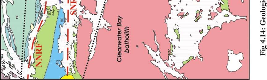
65 The TTWM shear zone, so named because it is parallel to the northwestern margin of the Town tonalite, is ~1200 m wide affecting the Pipestone Lake Group metavolcanic rocks and the Cross Lake Group clast-supported conglomerates. The dominant structure within the zone is the transposition foliation (S T ) defined by minerals. S T dips steeply to subvertically toward northwest. The WJ-NB shear zone is ~ m wide affecting the Pipestone Lake Group metavolcanic rocks transposed by S T foliation along the northwest shore of Nakow Bay. Its southeastern margin is gradational into moderately deformed granodiorite along the northwestern margin of the Cross Lake batholith. From southeast to northwest of the Nakow Bay, the intensity of S T foliation varies gradually from unfoliated (L-tectonites) to moderately foliated. South of the NR-PSL high-strain zone, this shear zone is ~2000 m wide, parallel to the Whiskey Jack Channel. There the northwestern boundary is the Clearwater Bay batholith and the southeastern boundary is the Whiskey Jack gneiss-molson Lake Domain. 4.5 Structural Analysis of the NR-PSL High-Strain Zone This ESE-trending high-strain zone starts at the west of Pipestone Lake of the map area and extends about 15 kilometers westwards along the Nelson River system between the Cross Island in the north and the Ross Island in the south (Fig 4.14). It deflects and merges into the NWB shear zone at the southwest of the Cross Lake greenstone belt immediately outside the map area. There are two faults parallel to the high-strain zone. They are the Northern Nelson River Fault (NNRF) and the Southern Nelson River Fault (SNRF), respectively (Fig 4.14). Based on style, overprinting relationships and sense of movement, three generations of deformation were 54
66 identified in NR-PSL high-strain zone and, following the convention of structural analysis, they are referred to as D 1, D 2, and D 3. However, this denotation does not imply any correlation of these structures with those outside the high-strain zone. The D 1 deformation is defined by isoclinal folds, intrafolial to a dominant transposition foliation. D 2 are generally open to tight asymmetrical folds overprinting the transposition foliation. Both D 1 and D 2 have a dextral sense of movement. D 3 is defined by macroscopic S-folds and en echélon veins observed in more competent layers parallel to the transposed foliations. The veins indicate a sinistral sense of movement. Mesoscopic F 3 folds associated with D 3 are difficult to recognize. D 1 dextral transpression is responsible for the transposition and the formation of the high-strain zone, whereas macroscopic F 3 S-folds dominate the map pattern of the central Cross Lake area D 1 Deformation Foliations The transposition of the bedding (S 0 ) forms a dominant composite foliation (S T ) occurring throughout the NR-PSL high-strain zone. S T strikes ESE. It dips gradually from moderately to vertically from south to north across the high-strain zone (Fig 4.14; Fig 4.15). There is a foliation (S 1 ) defined by preferred orientation of hornblende mineral and a local compositional layering. S 1 generally overprints F 1 isoclinal folds, but is axial planar to some. The geometrical relationship between S 1 and S T is constant, where not obscured by later deformation. S 1 is inclined to S T by an angle around o (Fig 4.15). Treating it as an S/C fabric, a dextral sense of shear of D 1 deformation is indicated. 55


67 56
68 Fig 4.15: Lower hemisphere equal area plot of S 0, S 1, and S T of the NR-PSL high-strain zone. Lineations There are four types of L 1 lineations defined respectively by preferred alignment of hornblende and biotite minerals on S 1, by the alignment of elongated clasts and pebbles, by the intersection of S 1 and S T, and by the fold axes of F 1, which will be described in the following. L 1 lineation defined by elongated clasts occurs only at the north margin of the high-strain zone near the southwest corner of the Cross Island. The first three types of L 1 lineations plunge steeply to subvertically towards northeast (Fig 4.16). L 1 lineations defined by F 1 fold axes pitch shallowly to steeply (see description below). 57
69 Fig 4.16: Lower hemisphere equal area plot of L 1 and F 1 fold axis of the NR-PSL high-strain zone. 58

 shallowly plunging F 1 folds preserved in pegmatite and Cross Lake Group sandstone (looking north, station number 349, southwest corner of the Cross Island); (b) F 1")
70 Folds On outcrops, F 1 isoclinal and commonly asymmetrical folds were observed, and these folds are best preserved in pegmatite (Fig 4.17). The only measurable F 1 folds are preserved in Cross Lake Group arkosic sandstone outcrops near the southwest corner of the Cross Island, where F 1 folds plunge shallowly to steeply (Fig 4.16). No macroscopic F 1 fold was recognized. a b Fig 4.17: F 1 folds: (a) shallowly plunging F 1 folds preserved in pegmatite and Cross Lake Group sandstone (looking north, station number 349, southwest corner of the Cross Island); (b) F 1 isoclinal fold with boudinaged limbs preserved in pegmatite and Cross Lake Group sandstone (subhorizontal section, looking west, station number 387, south margin of the Cross Island). 59

71 Other D 1 Structures Boudinage (Fig 4.18) is a common feature of the S T fabric at scales varying from millimeters to meters. Boudins are generally observed in pegmatite layers, amphibolite layers and quartz veins. Boudins are commonly on the limbs of F 1 folds, which indicate that they may be contemporary with folding. Boudin neck folds occur commonly, and are usually asymmetrical. The consistent Z style also indicates dextral sense of shear, which is consistent with the kinemtics of D 1 deformation. However, this asymmetry could also be due to D 2 modification, which is also characterized by a dextral sense of shear, and is possibly the progression of D 1 deformation. Fig 4.18: Boundins preserved in the Pipestone Lake Group basalt (picture showing vertical section, looking south, station number 208, along the Nelson River west channel near the north tip of the Ross Island). 60
72 Pegmatite dykes subparallel to S T are another common feature of D 1. Locally pegmatite layers are cut and dragged by S T, and the sense of shear is dextral. These pegmatites are folded (Fig 4.17). These D 1 related pegmatites are commonly overprinted by later stages of deformation (e.g. D 2 ) D 2 Deformation D 2 deformation is characterized by open to tight drag folds (F 2 ). F 2 folds commonly have a Z-geometry. They fold the S T and S 1. There is a weak axial plane foliation (S 2 ) defined by shape fabrics. S 2 strikes approximately northeast. Lineation L 2 defined by F 2 fold axis pitches steeply to downdip. Shear sense indicators (e.g., asymmetric boudinage) indicate dextral sense of movement. D 2 overprints D 1 transposed pegmatite dykes with open to tight drag folds (Fig 4.19). There is a gradation in the tightness of F 2 drag folds. I interpret them as a progressive deformation history. Based on repetition of lithological units and a systematic reversal of younging directions, a macroscopic F 2 fold is recognized near the southwest end of the Nakow Bay (Fig 4.14). This is an open syncline of F 1 /F 2 preserved in the Cross Lake Group trough-crossbedded, pebbly sandstone and the Cross Lake Group thinly bedded sandstone and siltstone (Fig 4.14; Fig 4.20). The fold axes plunge steeply to northeast-east. South of Nakow Bay between the two zone-parallel faults NNRF and SNRF, a macroscopic tight syncline was recognized based on the repetition of lithological units and a systematic reversal of younging directions preserved in the Cross Lake Group basal clast-supported and matrixsupported conglomerates (Fig 4.14; Fig 4.20). This F 1 /F 2 fold is referred to as Central Syncline (CS). The core of CS is the Cross Lake Group matrix-supported 61
, which led to a chain of S-folds of the south limb of CS (Fig 4.20). Fig 4.")
73 conglomerate. The north limb of CS is the Cross Lake Group clast-supported conglomerate, which is sheared and is in tectonic contact (i.e. NNRF) with underlying Pipestone Lake Group. CS was later refolded by sinistral D 3 deformation (see below), which led to a chain of S-folds of the south limb of CS (Fig 4.20). Fig 4.19: F 2 drag folds of pegmatite dykes preserved in the Cross Lake Group sandstone showing gradual development of folds: (1) initiation stage; (2) intermediate stage; (3) and (4) late stages of F 2 folding (station number 044, southwest corner of the Cross Island). 62


.")

74 Fig 4.20: Interpretive cross sections across the NR-PSL high-strain zone showing contact relationship and two generations of folds: an open F 1 /F 2 syncline is persevered in Cross Lake Group sandstones (see cross section C-C ). The dominant structure of the high-strain zone is a series of macroscopic S- folds. These F 3 folds refold an F 1 /F 2 syncline (CS, see cross section B-B, D-D, and text for detail). The trace of foliation shown in the cross section represents S T. 63
75 4.5.3 D 3 Deformation Normal to sigmoid en echélon quartz veins occur commonly in cal-silicate layers parallel to S T. They consistently indicate a sinistral sense of movement. The development of en echélon quartz veins also is an indication that the deformation condition is near the brittle/ductile transition. This and the sense of shear are in contrast to the sense of shear from D 1 to D 2. It was difficult to identify F 3 folds from F 2 folds at outcrop scale. S-folds were observed in the NR-PSL high-strain zone. These folds overprint S T openly to tightly, with axes plunging shallowly to steeply. Macroscopic F 3 S-folds dominate the overall geometry of the NR-PSL high-strain zone. The folds were recognized based on the repetition of lithological units of the Cross Lake Group conglomerates and a systematic reversal of younging direction. Near the east end of NR-PSL high-strain zone, a tight, steeply-inclined, ESE-trending upright fold was recognized (Fig 4.14; Fig 4.20) by the opposing younging direction indicated by cross-bedding preserved in the Cross Lake Group conglomerates. The fold is referred to as Eastern Fold (EF). Bedding is northeast-facing on the north fold limb, southeast-facing in the hinge area, and southwest-facing on the south limb. The south limb extends westwards and is dragged as a chain of continuous S-folds. Based on the repetition of the lithological units and systematic reversing younging directions, I interpret EF as a refolded fold of CS (Fig 4.14; Fig 4.20). The NR-PSL high-strain zone is primarily a D 1 deformation. F 2 can be interpreted as drag folds, developed largely due to transposition-foliation parallel shear. D 1 transpression shear led to complete transposition of bedding. D 2 64
76 deformation is likely the progression of D 1. The reversal in sense of shear during D 3 is responsible for producing reverse sense (i.e. sinistral) of structures observed in NR- PSL high-strain zone and its overall geometry. Based on the evidences that: (1) the older Pipestone Lake Group and Gunpoint Group overthrust on top of the Cross Lake Group; (2) S-C fabric developed in sheared Pipestone Lake Group volcanics indicating south-over-north shearing was reported by Parmenter (2002); (3) the metamorphic grade of the supracrustal rocks becomes lower northwards, I interpret that there is a vertical component of south side up of the NR-PSL high-strain zone. 4.6 The Northern Cross Lake Thrust The Cross Lake Greenstone Belt is bounded to the north by the Gods Lake- Pikwitonei Domain (> 3200 Ma). Within the mapping area, from northeast to southwest, the plutonic terrain is in contact with the Pipestone Group, the Gunpoint Group, the Cross Lake Group conglomerates, and the Cross Lake Group sandstones (Fig 3.1). The contact is a major northeast-trending fault system with dextral strike slip. The fault planes are presently steep. The vertical displacement component indicates dominantly relative uplift of the northwest side (Breedveld, 1998). This northeast trending fault is subparallel to the NE-trending shear zones in the southwestern portion of the Cross Lake greenstone belt outside of the mapping area; it trends more easterly and transects the NWB shear zone in the northeast region of the map area. The NCLBT transects the NR-PSL high-strain zone at the west end of the NR-PSL high-strain zone west of the mapping area. There the high-strain zone is deflected by the NCLBT and merged with it to NE-trending. It is suspected that this 65
77 fault developed as a shallowly to moderately-dipping fault with a west-side up reverse displacement component leading to the Eve Rapids granitoid masses overthrusted onto the supracrustal rocks. The NCLBT was then modified to a more steep orientation as the deformation advanced. 66
78 Chapter 5: Kinematic Interpretation Based on the structural analysis data presented in the previous chapter and the relationship between the structural domains, a kinematic evolution of the Cross Lake greenstone belt since the lithification of the Cross Lake group can be established. The kinematics of deformation described below is referred to the present geographic coordinates, since the crustal blocks have undoubtfully rotated during and after the deformation. The following sequence of deformation is clear from the map pattern, and nature of the contacts among structural domains. The two generations of deformation in Domains I and II and the formation of NE-trending shear zones are the earliest since the lithification of the Cross Lake group. This is followed by the juxtaposition of the NR-PSL high-strain zone with Domains I and II. The deformation structures within the NR-PSL high-strain zone could have been produced by the same deformation as those in Domains I and II but were strongly modified and rotated during the juxtaposition leading to the high-strain zone formation. The juxtaposition of the Eve Rapids Complex that is the development of the NCLBT is the latest event, which overprints the NE-trending shear zones and deflects the NR-PSL high-strain zone in the southwestern region of the greenstone belt. The kinematics of each of the above three events are discussed in more detail in the following. 5.1 ESE-WNW Convergence and Accompanying Crustal Thickening The first event of tectonic evolution for the CLGB is ESE-WNW directed 67
79 convergence and crustal thickening. The ESE-WNW convergence initiated the folding of the Cross Lake Group with fold hinge lines trending northeast and triggered crustal thickening that led to the transposition of all primary structures and/or structural features from previous unknown generations of deformation Interpreting the Structural Data The dominant structural feature of Domain I, Domain II, and NE-trending shear zones is the transposition foliation (S T ). Plot of structural data of Domain II (Fig 5.1) shows that the plot of bedding (S 0 ) is rather complicated, whereas that of S 1 is simpler as S 1 strikes more parallel to S T. The plot of S T is the simplest. This suggests that the transposition of S 0 and S 1 to S T. F 1 folds plunge variably from subhorizontal to subvertical whereas stretching lineations plunge steeply to vertically towards northeast. F 1 fold axes plot approximately along the average S T plan (Fig 5.1). This indicates that F 1 folds plunged shallowly when first produced. Extreme vertical stretch progressively rotated F 1 fold axes to subvertical from its initial subhorizontal direction, and tightened F 1 folds to isoclinal folds (Fig 5.2). Z-folds were observed on all scales in Domain I and Domain II. This suggests a dextral sense of shear of the NE-trending shear zones. Also, as described in previous chapters, the stratigraphic relationship of the Cross Lake Groups rocks between Domain I and II is unclear due to the NE-trending shear zone deformation (Fig 3.6). It is suggested that the panel of Domain II was juxtaposed onto the panel of Domain I with a large dextral displacement during NE-trending shear zone deformation. 68
80 Fig 5.1: Equal-area lower hemisphere plot of structural data of Domain II: (a) to (c) showing the transposition of bedding (S 0 ) and S 1 to S T direction; there is an angle between S T and the shear zone 69
 and (e). Fig 5.")
 the rotation of F 1 /F 2 fold axes to subvertical")

81 boundary, which indicates dextral sense of the shear; the rotation path of F 1 axis from initial subhorizontal to later subvertical is inferred in (d) and (e). Fig 5.2: Schematic block diagrams showing: (a) the folding of the CLBG with the fold hinge lines plunging shallowly initiated by ESE-WNW convergence; (b) the rotation of F 1 /F 2 fold axes to subvertical and the tightening of the folds resulted from significant vertical stretch. The progressive strain localization produced the NE-trending shear zones, and there is a dextral sense of shear of the deformation (see text for details). 70
82 5.1.2 The Shape of the Strain Ellipsoid Constructed from Clast Fabric A semi-quantificational analysis of ductile strain was undertaken in order to quantify the type of strain that the rocks in Domain I underwent during deformation. The analysis was done at the northwestern Cross Lake area (outcrop station numbers 390 and 391) where a suitable amount of clast-rich Gunpoint Group conglomerate outcrops exposed. Method In the field, three-dimensional structural data are not usually obtainable directly. For example, the three principal axes of clasts could not be measured from the outcrops of the Gunpoint Group. The following is a method to construct threedimensional fabric ellipsoid from two-dimensional sectional data. Shape preferred orientation of feldspar rich clasts was determined. Images of different planar sections of outcrops were collected using a digital camera. On each section, the strike and dip of that section was measured and marked on the outcrop (Fig 5.3). The camera was orientated normal to the surface. Each image was then printed out and analyzed. The orientation of the long axis relative to the strike of section, and the length of the long and short axes of each clast were measured. The average aspect ratio and orientation of long axes for each section were calculated, thus a sectional fabric ellipse is obtained. Fabric ellipses from at least three differently orientated sections are needed to construct a fabric ellipsoid. A fabric ellipsoid that represents the distribution in shape and orientation of the clasts was then calculated from these sectional data following the mathematics of Robin (2002) by using a MathCAD program written by Dr. Dazhi Jiang. 71

 section strikes 055, dips 82")
83 a Fig 5.3: Orientated photos showing different sections of a Gunpoint Group conglomerate outcrop near the northwest corner of the Cross Island selected to determine the shape of the strain ellipsoid: (a) section strikes 055, dips 82 o to north; (b) section strikes 031, dips 10 o to east (station number 391). b 72
84 Due to the complication of geological situations, many factors affect the determination of the strain ellipsoid including competence contrast between the clasts and matrix, and the original shape of the clasts. Therefore, the calculated fabric ellipsoid is only used to quantify the shape of finite strain ellipsoid rather than its magnitudes. Result The fabric ellipsoids were calculated for both outcrops, and were then plotted on Flinn Diagram (Fig 5.4). The Y-axis of the Flinn Diagram represents the ratio of the maximum axis (λ 1 ) to the intermediate axis (λ 2 ), and the X-axis represents the ratio of the intermediate axis (λ 2 ) to the minimum axis (λ 3 ) of the ellipsoid. Both ellipsoids plot above the plane strain line (K = 1) indicating that the strain field is highly constrictional (K > 1). The maximum axes of the fabric ellipsoids are orientated steeply to subvertically ( o and o ) towards northeast. It is readily seen from the result that the clasts have a strongly preferred alignment orientation on the subvertical dimension, but have poor alignment on the subhorizontal section (e.g., Fig 5.3; Fig 5.4). This suggests a coaxial deformation path close to uniaxial vertical stretching. This deformation path strongly suggests vertical stretch with little horizontal shear. 73
85 Fig 5.4: Plot of the fabric ellipsoids on Flinn diagram determined from a population of clasts in the Gunpoint Group at stations 390 and Tectonic Environment Combining field observation, structural data, results of fabric ellipsoid, and overall geometrical pattern, it appears clear that there is strong vertical stretch during the first deformation event of the CLGB. The general lack of vorticity on the horizontal section indicates that the deformation was not due to transpression. An inevitable explanation is vertical stretch resulting from gravity instability. A component of ESE-WNW convergence is believed to be responsible for the initiation of ~N040 o E trending folds with shallowly plunging fold hinge lines (Fig 5.2a). 74
86 Significant vertical stretch due to gravity instability leads to rotation of fold hinge lines toward subvertical orientation and tightening of the folds (Fig 5.2b). At a late stage of this event, ESE-WNW convergence was progressively localized into ~N40 o E shear zones. The axial plane trend of both the F 1 /F 2 folds and the NE-trending shear zones, and the dextral sense of shear of these shear zones suggest that the convergence vector is around 100 o ~120 o (Fig 5.5). The ESE-WNW convergence and accompany crustal thickening led to the isoclinal folding and transposition. It produced the dome-synformal structure of the CLGB with the form of an M -shaped series of upright folds (Fig 5.5). The NEtrending shear zones were resulted from progressive strain localization of the deformation. This is based on the observation that structures in the shear zones show similar geometric and kinematic characteristics to those outside the shear zones except that the intensity of deformation is much stronger in the shear zones. 75


87 76
; the second was the juxtaposition of the NR-PSL high-strain zone with Domains I and II; the last was the juxtaposition of the Eve Rapids")
.")
88 Fig 5.5: Cartoon showing the kinematic evolution of the CLGB: the first event was ESE-WNW convergence and accompany crustal thickening (see Fig 5.2 for the geometry of deformation on the vertical dimension); the second was the juxtaposition of the NR-PSL high-strain zone with Domains I and II; the last was the juxtaposition of the Eve Rapids complex which is the development of the NCLBT, it overprints the NE-trending shear zones and leads to the deflection of the NR-PSL highstrain zone in the southwestern region of the greenstone belt. 5.2 Juxtaposition of the NR-PSL High-Strain zone with Domains I and II All NE-trending shear zones within the mapping area are transected by the NR-PSL high-strain zone (Fig 5.5). The dominant structural feature of the NR-PSL high-strain zone is the ESE-trending transposed foliation (S T ), which overprints all structural elements outside of the zone, including the NE-trending shear zones. There are two major discontinuities within the NR-PSL high-strain zone: the two zone- 77
GEOLOGICAL INVESTIGATION IN THE ISLAND LAKE GREENSTONE BELT, NORTHWESTERN SUPERIOR PROVINCE, MANITOBA (PARTS OF NTS 53E/15 & 16) GS-18
 GS-18") GS-18 GEOLOGICAL INVESTIGATION IN THE ISLAND LAKE GREENSTONE BELT, NORTHWESTERN SUPERIOR PROVINCE, MANITOBA (PARTS OF NTS 53E/15 & 16) by S. Lin, H.D.M. Cameron, E.C. Syme and F. Corfu 1 Lin, S., Cameron,
GS-18 GEOLOGICAL INVESTIGATION IN THE ISLAND LAKE GREENSTONE BELT, NORTHWESTERN SUPERIOR PROVINCE, MANITOBA (PARTS OF NTS 53E/15 & 16) by S. Lin, H.D.M. Cameron, E.C. Syme and F. Corfu 1 Lin, S., Cameron,
GEOLOGY AND GEOCHRONOLOGY OF THE ISLAND LAKE GREENSTONE BELT, NORTHWESTERN SUPERIOR PROVINCE by J. Parks 1, S. Lin 1, M.T. Corkery and D.W.
 GS-17 GEOLOGY AND GEOCHRONOLOGY OF THE ISLAND LAKE GREENSTONE BELT, NORTHWESTERN SUPERIOR PROVINCE by J. Parks 1, S. Lin 1, M.T. Corkery and D.W. Davis 2 Parks, J., Lin, S., Corkery, M.T. and Davis, D.W.
Report of Activities 2003 Published by: Manitoba Industry, Economic Development and Mines Manitoba Geological Survey, 2003.
 Report of Activities 2003 Published by: Manitoba Industry, Economic Development and Mines Manitoba Geological Survey, 2003. ERRATA: The publisher/department name in the bibliographic reference cited immediately
Figure GS-25-1: General geology and domain subdivisions in northwestern Superior Province. 155
 GS-25 ASSEAN LAKE ANCIENT CRUST: AN UPDATE by M.T. Corkery, Ch.O. Böhm 1 and L.M Heaman 1 Corkery, M.T., Böhm, Ch.O. and Heaman, L.M. 2000: Assean Lake ancient crust: an update; in Report of Activities
The Development of L-tectonites in High-strain Zone Settings: A Multiscale Modeling Investigation
 Western University Scholarship@Western Electronic Thesis and Dissertation Repository September 2014 The Development of L-tectonites in High-strain Zone Settings: A Multiscale Modeling Investigation Weiyin
GEOLOGICAL INVESTIGATIONS IN THE GODS LAKE NARROWS AREA (PARTS OF NTS 53L/9 AND 53L/10)
") GS-18 GEOLOGICAL INVESTIGATIONS IN THE GODS LAKE NARROWS AREA (PARTS OF NTS 53L/9 AND 53L/10) by M.T. Corkery, S. Lin1, A.H. Bailes and E.C. Syme Corkery, M.T., Lin, S., Bailes, A.H., and Syme, E.C. 1999:
GS-18 GEOLOGICAL INVESTIGATIONS IN THE GODS LAKE NARROWS AREA (PARTS OF NTS 53L/9 AND 53L/10) by M.T. Corkery, S. Lin1, A.H. Bailes and E.C. Syme Corkery, M.T., Lin, S., Bailes, A.H., and Syme, E.C. 1999:
Geologic Structures. Changes in the shape and/or orientation of rocks in response to applied stress
 Geologic Structures Changes in the shape and/or orientation of rocks in response to applied stress Figure 15.19 Can be as big as a breadbox Or much bigger than a breadbox Three basic types Fractures >>>
INTRODUCTION REGIONAL GEOLOGY. N. St-Jean 1, L. Hunt 1 and R.L. Sherlock 1
 37. Preliminary Results from Mapping a New Exposure of the Basal Unconformity Between the Hearst and Larder Lake Assemblages, Skead Township, Northeastern Ontario N. St-Jean 1, L. Hunt 1 and R.L. Sherlock
GY 112 Lecture Notes Archean Geology
 GY 112 Lecture Notes D. Haywick (2006) 1 GY 112 Lecture Notes Archean Geology Lecture Goals: A) Time frame (the Archean and earlier) B) Rocks and tectonic elements (shield/platform/craton) C) Tectonics
Answers: Internal Processes and Structures (Isostasy)
") Answers: Internal Processes and Structures (Isostasy) 1. Analyse the adjustment of the crust to changes in loads associated with volcanism, mountain building, erosion, and glaciation by using the concept
Answers: Internal Processes and Structures (Isostasy) 1. Analyse the adjustment of the crust to changes in loads associated with volcanism, mountain building, erosion, and glaciation by using the concept
Chapter 15 Structures
 Chapter 15 Structures Plummer/McGeary/Carlson (c) The McGraw-Hill Companies, Inc. TECTONIC FORCES AT WORK Stress & Strain Stress Strain Compressive stress Shortening strain Tensional stress stretching
"When Gregor Samsa woke up one morning from unsettling dreams, he found himself changed into a monstrous bug. Metamorphosis, by Franz Kafka
 Metamorphosis "When Gregor Samsa woke up one morning from unsettling dreams, he found himself changed into a monstrous bug. Metamorphosis, by Franz Kafka Metamorphism The transformation of rock by temperature
2 Britain s oldest rocks: remnants of
 Britain s oldest rocks: remnants of Archaean crust 15 2 Britain s oldest rocks: remnants of Archaean crust 2.1 Introduction Owing to the complex nature of extremely old deformed rocks, the standard methods
Archean Terranes. Archean Rocks. Southeastern Africa. West Greenland. Kaapvaal Craton. Ancient Gneiss Complex
 Archean Terranes Archean Rocks Chapter 15A >2.5 Gy old Younger supracrustal sequences Greenstone belts Calc-alkaline metavolcanic rocks Older gneiss complexes Quartzo-feldspathic rocks Tonalites and migmatites
IMSG Post-conference Field Guide
 IMSG 2017 - Post-conference Field Guide Jérémie Lehmann, Marlina Elburg and Trishya Owen-Smith The purpose of this short field excursion on Wednesday 18 January is to show a variety of rocks that make
GS-14. Bernic Lake Formation General geology. Summary. Introduction
 GS-14 Preliminary results from geological mapping of the Bernic Lake Formation, Bird River greenstone belt, southeastern Manitoba (NTS 52L6) by P.D. Kremer 1 Kremer, P.D. 2005: Preliminary results from
Strike-Slip Faults. ! Fault motion is parallel to the strike of the fault.
 Strike-Slip Faults! Fault motion is parallel to the strike of the fault.! Usually vertical, no hanging-wall/footwall blocks.! Classified by the relative sense of motion. " Right lateral opposite block
Lecture 6 Folds, Faults and Deformation Dr. Shwan Omar
 Fold: A fold is a bend or wrinkle of rock layers or foliation; folds form as a sequence of ductile deformation. Folding is the processes by which crustal forces deform an area of crust so that layers of
NAME HOMEWORK ASSIGNMENT #3 MATERIAL COVERS CHAPTERS 8, 9, 10, 11
 NAME HOMEWORK ASSIGNMENT #3 MATERIAL OVERS HAPTERS 8, 9, 10, 11 Assignment is due the beginning of the class period on November 23, 2004. Answers for each chapter will be discussed in class, as Exam #3
7 Sedimentation and tectonics at a mid- Ordovician to Silurian active margin
 80 Mountain Building in Scotland 7 Sedimentation and tectonics at a mid- Ordovician to Silurian active margin 7.1 Introduction In mid-ordovician to Silurian times, the Grampian mountains underwent exhumation,
Chapter 8 Lecture. Earth: An Introduction to Physical Geology. Twelfth Edition. Metamorphism. Rocks. Tarbuck and Lutgens Pearson Education, Inc.
 Chapter 8 Lecture Earth: An Introduction to Physical Geology Twelfth Edition Metamorphism and dmetamorphic Rocks Tarbuck and Lutgens Chapter 8 Metamorphic Rocks What Is Metamorphism? Metamorphism means
You must take the exam in the lecture section for which you are registered. Any exceptions must be cleared with the instructor in advance.
 Geo 101, Fall 2000 Review Questions for Final Exam GEOLOGIC TIME AND FOLDING AND FAULTING THE FINAL EXAM FOR MWF CLASS WILL BE TUESDAY 1400 THE FINAL EXAM FOR TR CLASS WILL BE FRIDAY 930 These questions
GEOLOGY OF THE NICOLA GROUP BETWEEN MISSEZULA LAKE AND ALLISON LAKE
 GEOLOGY OF THE NICOLA GROUP BETWEEN MISSEZULA LAKE AND ALLISON LAKE (92H/15E. 10E1 By V. A. Preto INTRODUCTION Mapping was continued southward from the area covered in 1973 and an additional 55 square
=%REPORT RECONNAISSANCE OF CHISHOLM LAKE PROSPECT. October 25, 1977
 =%REPORT ON FIELD RECONNAISSANCE OF CHISHOLM LAKE PROSPECT October 25, 1977 Bruce D. Vincent Imperial Oil Limited, Minerals - Coal, CALGARY, ALBERTA CHISHOLM LAKE PROSPECT Introduction The Chisholm Lake
How mountains are made. We will talk about valleys (erosion and weathering later)
") How mountains are made We will talk about valleys (erosion and weathering later) http://www.ilike2learn.com/ilike2learn/mountainmaps/mountainranges.html Continent-continent plate convergence Less dense,
How mountains are made We will talk about valleys (erosion and weathering later) http://www.ilike2learn.com/ilike2learn/mountainmaps/mountainranges.html Continent-continent plate convergence Less dense,
Mist Mis y Lake y Lak Mapping Progr ogr
 Far North Geomapping Initiative: Preliminary Results From Geological Mapping in the Misty Lake Area, Northwestern Manitoba Paul Kremer, Chris Couëslan, Anders Carlson (MGS) Nicole Rayner (GSC) Misty Lake
Copyright McGraw-Hill Education. All rights reserved. No reproduction or distribution without the prior written consent of McGraw-Hill Education
 Copyright McGraw-Hill Education. All rights reserved. No reproduction or distribution without the prior written consent of McGraw-Hill Education Tibetan Plateau and Himalaya -southern Asia 11.00.a VE 10X
CHAPTER VI CONCLUSIONS
 CHAPTER VI CONCLUSIONS In this Chapter, salient observations made in understanding the various tectonothermal events, including U-Pb in-situ monazite geochronology of Sargur schists and granulites exposed
1. classic definition = study of deformed rocks in the upper crust
 Structural Geology I. Introduction 1. classic definition = study of deformed rocks in the upper crust deformed includes translation, rotation, and strain (change of shape) All rocks are deformed in some
Section 10.1 The Nature of Volcanic Eruptions This section discusses volcanic eruptions, types of volcanoes, and other volcanic landforms.
 Chapter 10 Section 10.1 The Nature of Volcanic Eruptions This section discusses volcanic eruptions, types of volcanoes, and other volcanic landforms. Reading Strategy Previewing Before you read the section,
KEY CHAPTER 12 TAKE-HOME QUIZ INTERNAL STRUCTURES AND PROCESSES Score Part B = / 55 PART B
 GEOLOGY 12 KEY CHAPTER 12 TAKE-HOME QUIZ INTERNAL STRUCTURES AND PROCESSES Score Part B = / 55 PART B CHAPTER 12 Isostacy and Structural Geology 1. Using the terms below, label the following diagrams and
How to Build a Mountain and other Geologic Structures. But first a short review
 How to Build a Mountain and other Geologic Structures But first a short review Where do we see deep earthquakes? What is happening there? What can happen at a plate boundary? 1. Plates can move apart
Strain analysis of Archean rocks from the Virginia Horn area, NE Minnesota
 Strain analysis of Archean rocks from the Virginia Horn area, NE Minnesota Ben Christensen Undergraduate Thesis under Jim Welsh Gustavus Adolphus College Geology Abstract The Virginia Horn refers to the
Appendix 11. Geology. of the. I60 area
 Appendix 11 Geology of the I60 area 1. Locality The locality of the I60 area is as follows; Northwestern corner; UTM_EW 530513, UTM_NS 7345741 Southwestern corner; UTM_EW 530418, UTM_NS 7301454 Northeastern
Crustal Deformation Earth - Chapter Pearson Education, Inc.
 Crustal Deformation Earth - Chapter 10 Structural Geology Structural geologists study the architecture and processes responsible for deformation of Earth s crust. A working knowledge of rock structures
Geology of Quesnel and Stikine terranes and associated porphyry deposits. Jim Logan Paul Schiarizza
 Geology of Quesnel and Stikine terranes and associated porphyry deposits Jim Logan Paul Schiarizza Quesnel and Stikine terranes Major cordilleran terranes characterized by similar Late Triassic Early Jurassic
Chapter 10: Volcanoes and Other Igneous Activity Section 1: The Nature of Volcanic Eruptions I. Factors Affecting Eruptions Group # Main Idea:
 Chapter 10: Volcanoes and Other Igneous Activity Section 1: The Nature of Volcanic Eruptions I. Factors Affecting Eruptions Group # A. Viscosity Group # B. Dissolved Gases Group # II. Volcanic Material
How to Build a Mountain and other Geologic Structures. But first, questions
 How to Build a Mountain and other Geologic Structures But first, questions Questions your students might ask How were Montana s mountains formed? How old are the mountains? What are the different ways
Provided by Tasa Graphic Arts, Inc. for An Introduction to Structural Methods DVD-ROM
 Provided by Tasa Graphic Arts, Inc. for An Introduction to Structural Methods DVD-ROM http://www.tasagraphicarts.com/progstruct.html AN INTRODUCTION TO STRUCTURAL METHODS - DETAILED CONTENTS: (Navigate
Topics Laramide Orogeny: Late Cretaceous to Early Eocene Reading: GSA DNAG volume 3, Ch. 6
 Topics Laramide Orogeny: Late Cretaceous to Early Eocene Reading: GSA DNAG volume 3, Ch. 6 Late Cretaceous to early Eocene New patterns developed 5 main regions Tectonic interpretations Post-Laramide events
Lab: Metamorphism: minerals, rocks and plate tectonics!
 Introduction The Earth s crust is in a constant state of change. For example, plutonic igneous rocks are exposed at the surface through uplift and erosion. Many minerals within igneous rocks are unstable
What Causes Rock to Deform?
 Crustal Deformation Earth, Chapter 10 Chapter 10 Crustal Deformation What Causes Rock to Deform? Deformation is a general term that refers to all changes in the shape or position of a rock body in response
Plate Tectonics. Structure of the Earth
 Plate Tectonics Structure of the Earth The Earth can be considered as being made up of a series of concentric spheres, each made up of materials that differ in terms of composition and mechanical properties.
Crustal Deformation. (Building Earth s Surface, Part 1) Science 330 Summer Mapping geologic structures
 Science 330 Summer Mapping geologic structures") Crustal Deformation (Building Earth s Surface, Part 1) Science 330 Summer 2005 Mapping geologic structures When conducting a study of a region, a geologist identifies and describes the dominant rock structures
Crustal Deformation (Building Earth s Surface, Part 1) Science 330 Summer 2005 Mapping geologic structures When conducting a study of a region, a geologist identifies and describes the dominant rock structures
Bedrock mapping and geological characterization in the northern Glennie domain, west-central Reindeer Zone
 Bedrock mapping and geological characterization in the northern Glennie domain, west-central Reindeer Zone Samantha Van De Kerckhove, Ryan Morelli and Dylan Deck Saskatchewan Geological Open House, 2017
CHAPTER Va : CONTINUOUS HETEROGENEOUS DEFORMATION
 Va-1 INTRODUCTION Heterogeneous deformation results from mechanical instabilities (folding and boudinage) within an heterogeneous material or from strain localization in an homogeneous material (shear
Chapter 4 Rocks & Igneous Rocks
 Chapter 4 Rocks & Igneous Rocks Rock Definition A naturally occurring consolidated mixture of one or more minerals e.g, marble, granite, sandstone, limestone Rock Definition Must naturally occur in nature,
LOW GRADE PRECAMBRIAN ROCKS OF THE CENTRAL GRAVELLY RANGE, SW MONTANA
 LOW GRADE PRECAMBRIA ROCKS OF THE CETRAL GRAVELLY RAGE, SW MOTAA ELIZABETH KLEI Amherst College Sponsor: Tekla Harms and Jack Cheney ITRODUCTIO Laramide uplift of the southern Gravelly Range of southwestern
New geologic mapping + and associated economic potential on northern Hall Peninsula, Baffin Island, Nunavut
 New geologic mapping + and associated economic potential on northern Hall Peninsula, Baffin Island, Nunavut Holly Steenkamp, M.Sc. Regional Mapping Geoscientist David Mate, M.Sc. Chief Geologist November
3. GEOLOGY. 3.1 Introduction. 3.2 Results and Discussion Regional Geology Surficial Geology Mine Study Area
 3. GEOLOGY 3.1 Introduction This chapter discusses the baseline study of the geology and mineralization characteristics of the mine study area. The study consolidates existing geological data and exploration
Big Island Field Trip
 Big Island Field Trip Space Still Available Group Airline Tickets May be available if enough people sign on If interested send email to Greg Ravizza Planning Meeting Next Week Will
Plate Tectonics. entirely rock both and rock
 Plate Tectonics I. Tectonics A. Tectonic Forces are forces generated from within Earth causing rock to become. B. 1. The study of the origin and arrangement of Earth surface including mountain belts, continents,
GEOLOGY OF THAILAND (METAMORPHIC ROCKS)
") GEOLOGY OF THAILAND (METAMORPHIC ROCKS) High-Grade Metamorphic Rocks (Precambrian?) Low-Grade Metamorphic Rocks (Lower Paleozoic) 1 THAILAND EXPLANATION Lower Paleozoic Rocks (Low Grade) Precambrian (?)
GEOLOGY OF THAILAND (METAMORPHIC ROCKS) High-Grade Metamorphic Rocks (Precambrian?) Low-Grade Metamorphic Rocks (Lower Paleozoic) 1 THAILAND EXPLANATION Lower Paleozoic Rocks (Low Grade) Precambrian (?)
GLY 155 Introduction to Physical Geology, W. Altermann. Press & Siever, compressive forces. Compressive forces cause folding and faulting.
 Press & Siever, 1995 compressive forces Compressive forces cause folding and faulting. faults 1 Uplift is followed by erosion, which creates new horizontal surface. lava flows Volcanic eruptions cover
Introduction. Introduction. Chapter 7. Important Points: Metamorphism is driven by Earth s s internal heat
 Chapter 7 Metamorphism and Metamorphic Rocks Introduction Metamorphism - The transformation of rocks, usually beneath Earth's surface, as the result of heat, pressure, and/or fluid activity, produces metamorphic
GY111 Earth Materials Practice Final Exam
 I. True/False Questions: circle a T for true or F for false (10% total -or- 0.5 per) 1. (T F) The Uranium used in nuclear power plants may explode if not controlled properly. 2. (T F) Natural Gas is an
Lab 6: Metamorphic Rocks
 Introduction The Earth s crust is in a constant state of change. For example, plutonic igneous rocks are exposed at the surface through uplift and erosion. Many minerals within igneous rocks are unstable
Convergent plate boundary.
 Crustal Deformation Convergent plate boundary http://my.execpc.com/~acmelasr/mountains/geogramsnf.html Plate Tectonic Settings and Magma Where plates CONVERGE, water is driven off the subducting plate,
Appendix A2: Detailed description of all results
 Appendix A2: Detailed description of all results This Appendix presents detailed descriptions of all results in this study. It is presented separately in order to streamline the main paper, and to provide
11.1 Rock Deformation
 Tarbuck Lutgens Mountain Building 11.1 Rock Deformation Factors Affecting Deformation Factors that influence the strength of a rock and how it will deform include temperature, confining pressure, rock
Structural Geology and Geology Maps Lab
 Structural Geology and Geology Maps Lab Mesa College Geology 101 Lab Ray Rector: Instructor Structural Geology Lab Pre-Lab Resources Pre-Lab Internet Links 1) Fundamentals of Structural Geology 2) Visualizing
Earth Science, (Tarbuck/Lutgens) Chapter 10: Mountain Building
 Chapter 10: Mountain Building") Earth Science, (Tarbuck/Lutgens) Chapter 10: Mountain Building 1) A(n) fault has little or no vertical movements of the two blocks. A) stick slip B) oblique slip C) strike slip D) dip slip 2) In a(n) fault,
Earth Science, (Tarbuck/Lutgens) Chapter 10: Mountain Building 1) A(n) fault has little or no vertical movements of the two blocks. A) stick slip B) oblique slip C) strike slip D) dip slip 2) In a(n) fault,
Metamorphism: summary in haiku form
 Metamorphism & Metamorphic Rocks Earth, Chapter 8 Metamorphism: summary in haiku form Shape-shifters in crust. Just add heat and/or pressure. Keep it solid please! What Is Metamorphism? Metamorphism means
GSTT Technical Note. September 4, Field Trip - Northern Range. Western (Mid-Crustal) Tectonic Domain. STOP 1: Upper Lady Chancellor Road
 Tectonic Domain. STOP 1: Upper Lady Chancellor Road") GSTT Technical Note September 4, 2001 P.O. Box 3524, La Romain, Trinidad and Tobago W.I Web address: www.gstt.org, Editor: millikm1@bp.com Field Trip - Northern Range Systematic east to west variations
GSTT Technical Note September 4, 2001 P.O. Box 3524, La Romain, Trinidad and Tobago W.I Web address: www.gstt.org, Editor: millikm1@bp.com Field Trip - Northern Range Systematic east to west variations
B) color B) Sediment must be compacted and cemented before it can change to sedimentary rock. D) igneous, metamorphic, and sedimentary rocks
 color B) Sediment must be compacted and cemented before it can change to sedimentary rock. D) igneous, metamorphic, and sedimentary rocks") 1. Which characteristic of nonsedimentary rocks would provide the least evidence about the environment in which the rocks were formed? A) structure B) color C) crystal size D) mineral composition 2. Which
1. Which characteristic of nonsedimentary rocks would provide the least evidence about the environment in which the rocks were formed? A) structure B) color C) crystal size D) mineral composition 2. Which
Distortion Effects of Faults on Gravity Worm Strings Robin O Leary
 Distortion Effects of Faults on Gravity Worm Strings Robin O Leary Problem Can upward continued gravity anomaly worm strings be used as a tool to determine the dip direction of an offsetting structure
Structure and history of the Kern Canyon fault system: introduction and thesis overview
 1 Chapter 1 Structure and history of the Kern Canyon fault system: introduction and thesis overview Exposures of fault zones from the surface to deep levels afford an opportunity to study the transition
lecture 7 Foliations & lineations
 Kristallingeologie lecture 7 Foliations & lineations 28 participants Results test A, 2008 Maximum 70 points Pass!35 points (!50%) Best result 67 points Average result 54 points ("2.3) Worst result 30 points
Mishi Lake Gold Property Mishibishu Lake Area, Wawa
 Mishi Lake Gold Property Mishibishu Lake Area, Wawa Location, Accessibility, Infrastructure and Local Resources The property is located 40 km west of Wawa, Ontario, in the Mishibishu Lake Area, Sault Ste.
Maine Geologic Facts and Localities October, Lobster Lake, Maine. Text by Robert G. Marvinney. Maine Geological Survey
 Maine Geologic Facts and Localities October, 1998 Lobster Lake, Maine 45 o 51 7.91 N, 69 o 30 53.88 W Text by Robert G. Marvinney, Department of Agriculture, Conservation & Forestry 1 Map by Introduction
Quiz 1. 3) Which of the following planetary bodies has the least number of impact craters on its surface? A) Mercury B) Mars C) the Moon D) Earth
 Which of the following planetary bodies has the least number of impact craters on its surface? A) Mercury B) Mars C) the Moon D) Earth") Quiz 1 1) Earth's atmosphere is unique among the moons and planets in that A) it has a nitrogen (N2) rich atmosphere. B) it is rich in oxygen (O2) and nitrogen (N2). C) it is rich in carbon dioxide because
Quiz 1 1) Earth's atmosphere is unique among the moons and planets in that A) it has a nitrogen (N2) rich atmosphere. B) it is rich in oxygen (O2) and nitrogen (N2). C) it is rich in carbon dioxide because
Structural geology and gold metallogeny of the New Britannia mine area, Snow Lake, Manitoba
 Structural geology and gold metallogeny of the New Britannia mine area, Snow Lake, Manitoba Chris Beaumont-Smith Manitoba Geological Survey Boundary zone New Britannia Trans-Hudson Orogen 50 km 100 km
Stress and Strain. Stress is a force per unit area. Strain is a change in size or shape in response to stress
 Geologic Structures Geologic structures are dynamically-produced patterns or arrangements of rock or sediment that result from, and give information about, forces within the Earth Produced as rocks change
Practice Test Rocks and Minerals. Name. Page 1
 Name Practice Test Rocks and Minerals 1. Which rock would be the best source of the mineral garnet? A) basalt B) limestone C) schist D) slate 2. Which mineral is mined for its iron content? A) hematite
Geology of Neoproterozoic to Cambrian Adelaide Geosyncline and Cambrian Delamerian Orogen
 Geology of Neoproterozoic to Cambrian Adelaide Geosyncline and Cambrian Delamerian Orogen W. V. Preiss Geological Survey Branch, PIRSA Link line traverses Flinders Ranges to join western end of E-W Curnamona
1. are most likely to study the images sent back from Mars. A. Astronomers B. Geologists C. Doctors D. Engineers
 1. are most likely to study the images sent back from Mars. A. Astronomers B. Geologists C. Doctors D. Engineers 2. When did the Earth form? A. About 540 million years ago B. About 2.5 billion years ago
GEOLOGIC MAPS PART II
 EARTH AND ENVIRONMENT THROUGH TIME LABORATORY - EES 1005 LABORATORY FIVE GEOLOGIC MAPS PART II Introduction Geologic maps of orogenic belts are much more complex than maps of the stable interior. Just
Geomorphology Final Exam Study Guide
 Geomorphology Final Exam Study Guide Geologic Structures STRUCTURAL GEOLOGY concerned with shapes, arrangement, interrelationships of bedrock units & endogenic (within) forces that cause them. Tectonic
Chapter 8 10/19/2012. Introduction. Metamorphism. and Metamorphic Rocks. Introduction. Introduction. The Agents of Metamorphism
 Chapter 8 Metamorphism Introduction Metamorphism - The transformation of rocks, usually beneath Earth's surface, as the result of heat, pressure, and/or fluid activity, produces metamorphic rocks During
Trip B-2 VARIATIONS IN L- AND S-TECTONITE ON THE NORTHERN BOUNARY OF THE PISECO LAKE SHEAR ZONE, ADIRONDACK MOUNTAINS, NEW YORK
 Trip B-2 VARIATIONS IN L- AND S-TECTONITE ON THE NORTHERN BOUNARY OF THE PISECO LAKE SHEAR ZONE, ADIRONDACK MOUNTAINS, NEW YORK DAMIAN PIASCHYK 1, DAVID VALENTINO 2, GARY SOLAR 3, JEFFREY R. CHIARENZELLI
Earth Science - Lab #11 Geologic Time
 Earth Science - Lab #11 Geologic Time Page # Below are standard geologic symbols for the 3 main categories of rocks. Although these symbols are not universal, they are generally accepted by most geologists
Igneous Rocks. Sedimentary Rocks
 Earth Sciences 083F Plate Tectonics Exercises Plate tectonics is a model for the dynamic behaviour of Earth s lithosphere. Outlining stable areas of lithosphere are narrow zones (plate boundaries) in which
FINAL EXAM Crustal Deformation CONVERGE DIVERGENT PLATES MANTLE PLUMES FLUX BASALTIC GRANITIC
 Crustal Deformation Reading: Chapter 10 Pages 283-294 FINAL EXAM 8 to 10 AM, THURSDAY DEC. 6 HERE: Natural Science 101 BRING A SCAN TRON TURN IN YOUR REVIEW QUESTIONS BEFORE THE TEST, PICK UP WHEN YOU
Questions and Topics
 Plate Tectonics and Continental Drift Questions and Topics 1. What are the theories of Plate Tectonics and Continental Drift? 2. What is the evidence that Continents move? 3. What are the forces that
Chapter 16. Mountain Building. Mountain Building. Mountains and Plate Tectonics. what s the connection?
 Chapter 16 Mountains and Plate Tectonics what s the connection? Mountain Building Most crustal deformation occurs along plate margins. S.2 Active Margin Passive Margin Mountain Building Factors Affecting
As compaction and cementation of these sediments eventually occur, which area will become siltstone? A) A B) B C) C D) D
 A B) B C) C D) D") 1. A student obtains a cup of quartz sand from a beach. A saltwater solution is poured into the sand and allowed to evaporate. The mineral residue from the saltwater solution cements the sand grains together,
1. A student obtains a cup of quartz sand from a beach. A saltwater solution is poured into the sand and allowed to evaporate. The mineral residue from the saltwater solution cements the sand grains together,
Introduction to Prospecting. Session Two Geology
 Introduction to Prospecting Session Two Geology The Earth Earth is 4.6 billion years old (Ba). Bacteria & algae +3.5 Ba. Microscopic animals ~2 Ba. Animals ~600 million years (Ma) old. Mankind about 100,000
Igneous Rocks. Sedimentary Rocks. Metamorphic Rocks
 Name: Date: Igneous Rocks Igneous rocks form from the solidification of magma either below (intrusive igneous rocks) or above (extrusive igneous rocks) the Earth s surface. For example, the igneous rock
Metamorphic history of Nuvvuagittuq greenstone belt, Northeastern Superior Province, Northern Quebec, Canada
 Metamorphic history of Nuvvuagittuq greenstone belt, Northeastern Superior Province, Northern Quebec, Canada By: Majnoon, M., Supervisor: Minarik, W.G., Committee members: Hynes, A., Trzcienski, W.E. 1.
APPENDIX 2 Table 2. Sample descriptions
 Table 2. descriptions 225 Felsic gneiss, fine-grained and very light-gray. From the upper part of the lower of the two layers, which connect. 226 Amphibolite, even-grained, fine-grained, medium-gray, little
DÉCOUVERTE Positioned for Discovery in James Bay, Quebec. Investor Presentation, January 2018 by Danae Voormeij, MSc, PGeo
 DÉCOUVERTE Positioned for Discovery in James Bay, Quebec Investor Presentation, January 2018 by Danae Voormeij, MSc, PGeo Location Maps and Infrastructure Location: Durango Resources 100% owned Découverte
Metamorphism / Metamorphic Rocks
 Metamorphism / Metamorphic Rocks Metamorphism: occurs when rocks are subjected to heat, pressure, and/or other environmental conditions - The rock remains a solid during this time period - Why Should You
Chapter. Mountain Building
 Chapter Mountain Building 11.1 Rock Deformation Factors Affecting Deformation Factors that influence the strength of a rock and how it will deform include temperature, confining pressure, rock type, and
GCE AS/A level 1211/01 GEOLOGY GL1 Foundation Unit
 Surname Centre Number Candidate Number Other Names 2 GCE AS/A level 1211/01 GEOLOGY GL1 Foundation Unit S15-1211-01 A.M. MONDAY, 11 May 2015 1 hour For s use Question Maximum Mark 1. 15 2. 14 Mark Awarded
GS Manitoba Geological Survey
 GS2017-2 In Brief: Scheelite mineralization was investigated as a potential analog to the Monument Bay Au-W deposit A crustal-scale fault defines the contact between supracrustal and plutonic rocks Disseminated
Full file at CHAPTER 2 The Way the Earth Works: Plate Tectonics
 CHAPTER 2 The Way the Earth Works: Plate Tectonics MULTIPLE CHOICE 1. Wegener proposed continental drift after he observed evidence from fossils, glacial deposits, and the fit of the continents that suggested
Lecture 9 faults, folds and mountain building
 Lecture 9 faults, folds and mountain building Rock deformation Deformation = all changes in size, shape, orientation, or position of a rock mass Structural geology is the study of rock deformation Deformation
Evolution of Continents Chapter 20
 Evolution of Continents Chapter 20 Does not contain complete lecture notes. Mountain belts Orogenesis the processes that collectively produce a mountain belt Includes folding, thrust faulting, metamorphism,
CRUSTAL DEFORMATION. Chapter 10
 CRUSTAL DEFORMATION and dgeologic Structures t Chapter 10 Deformation Df Deformation involves: Stress the amount of force applied to a given area. Types of Stress: Confining Stress stress applied equally
GEOLOGIC TIME. Smith and Pun, Chapter 7 DETERMINING THE ORDER OF EVENTS
 GEOLOGIC TIME Smith and Pun, Chapter 7 DETERMINING THE ORDER OF EVENTS Examination of ancient rocks reveals the history of our planet. Sedimentary and volcanic rocks record processes that occur on the