Preliminary Geotechnical Review and Site Reconnaissance CBJ Parking Structure Juneau, Alaska DMA Job No
|
|
|
- Helena Robinson
- 5 years ago
- Views:
Transcription
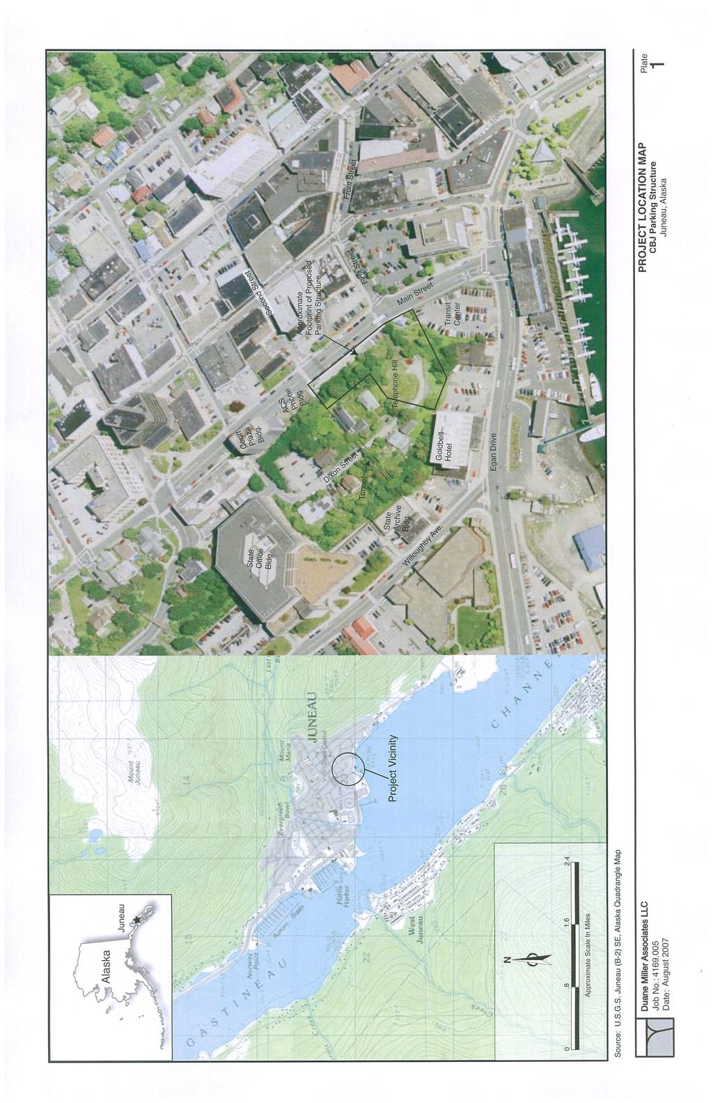
1 Tetra Tech, Inc. 230 South Franklin, Suite 212 Juneau, Alaska Attention: Donald Beard, P.E. Subject: Final Report Preliminary Geotechnical Review and Site Reconnaissance CBJ Parking Structure Juneau, Alaska DMA Job No This letter presents the results of our preliminary geotechnical review and site reconnaissance to support design of the proposed parking structure on Telephone Hill in Juneau, Alaska. The parking structure is being developed by the City and Borough of Juneau (CBJ). The proposed parking structure site is a large bedrock hill between Main Street and Egan Drive in downtown Juneau (Plate 1). The site abuts Main Street on the north and east, the Transit Center on the south, and intersects Dixon Street on the west. Bedrock outcrops are exposed at several locations along the perimeter of Telephone Hill and an unlined tunnel crosses under the hill on the northerly end of the project. The conceptual design shows three levels of parking with about 500 spaces. The structure is situated primarily over bedrock, but the southeast corner near the Transit Center and the east wall facing Main Street could extend out over unconsolidated materials. The structure will be a nominal 40 feet tall with the bottom floor at about Elevation 28 feet mean lower low water (MLLW). Plate 2 presents a preliminary plan view of the proposed parking structure. The work described in this report was conducted in accordance with our proposal to Tetra Tech/KCM, Inc., dated February 28, The purpose of our work was to evaluate the soil and rock conditions at the proposed parking structure site and to develop conclusions and preliminary recommendations regarding foundation design. During the work we consulted with Mr. Don Beard, P.E., of Tetra Tech/KMC, Inc., and Mr. Rorie Watt, P.E., of the CBJ. Project Setting, Geology, and Climate The city of Juneau is located on the northeast side of Gastineau Channel on the alluvial fan and delta formed at the mouth of Gold Creek. Gastineau Channel is a straight, structural trough trending northwest and separating Douglas Island from the mainland. The mountains on the mainland side rise steeply to 2,000 to 3,000 feet elevation and then more gently to heights of 4,000 feet. The bottom of Gastineau Channel is at a depth of about 150 feet.
2 Page 2 The Juneau area is underlain by bedrock consisting of layered greenstone, graywacke, slate, greenschist and metavolcanic breccias. The bedrock is exposed on the slopes that were scraped clean by Quaternary glaciation. Over much of the lower ground, the bedrock is blanketed by post-glacial soil deposits and man-made fill. The soils can be grouped by the means of deposition: manmade fill (including mine tailings), muskeg, slope-wasting deposits, alluvial deposits, deltaic deposits, beach deposits, marine deposits and glacial and glacio-marine deposits. Soils near the south end of the parking structure site are dominated by manmade fill over intertidal (beach) and marine deposits. Juneau has a mild, maritime climate. Average summer temperatures range from 44 degrees Farenheit ( F) to 65 F; winter temperatures range from 25 F to 35 F. Annual precipitation is 92 inches in downtown Juneau, and 54 inches ten miles north at the airport. Snowfall averages 101 inches per year. The project site lies within the downtown area and is surrounded by multistory office buildings, commercial structures, private residences, and borough infrastructure. Nearby buildings include the Goldbelt Hotel, the State Archive Building, the State Office Building complex, the Court Plaza, and the JD Phone Co. Building. Several one- and two-story residential structures owned by the CBJ are located on Telephone Hill near the south end of Dixon Street. Remnants of previous building foundations (sections of concrete footings and stemwalls) are visible along the northeast perimeter of Telephone Hill, parallel to Main Street. The Second Street Tunnel is an unlined tunnel beneath Telephone Hill that runs between Main Street and Willoughby Avenue (see Plate 1). The tunnel is oriented along a northeasterly axis, sloping gently upward from about elevation 30 feet at the south portal to elevation 46 feet at the north portal. The interior passage is roughly 10 feet wide by 10 feet high by 300-feet-long. Along the floor are a concrete sidewalk (southeast side) and a nominal 16-inch diameter partially-buried water line (northwest side). Additional utilities may also be buried in the tunnel floor. Timber walls with locked doors cover the portals at both ends. The northerly wall of the parking structure will be immediately adjacent to about 65 feet of the tunnel alignment. Photographs of the tunnel are included in Appendix A. Existing Geotechnical and Foundation Data Review Two maps published by the U.S. Geological Survey (Ford & Brew, 1973; and Miller, 1975) present a thorough overview of geologic conditions in the Juneau area. Using general information provided in these maps, we began the investigation of site-specific conditions by reviewing other available geotechnical and foundation information for this area of Juneau. The following paragraphs summarize the results of pertinent previous work. In August 2005, BBFM Engineers Inc., completed an update to a condition survey for the State Archive Building located west of the site on Willoughby Avenue, near the south portal of the Second Street Tunnel (see Plate 1). The State Archive is a two-story steel frame building that was designed and constructed as two
3 Page 3 separate structures with a joint between them. The west or front part of the structure is founded on concrete spread footings over fill; and the east or back part of the structure is founded on bedrock. The west part of the structure has settled and rotated away from the east part due to settlement of the spread footings relative to the bedrock foundation. A vertical offset of approximately 1-1/2 inches and a horizontal displacement of as much as 3 inches has occurred at the building joint. In the early 1970 s, twenty-nine test holes were drilled on the Goldbelt Hotel property, southwest of the site (see Plate 1). Test hole locations and logs of subsurface strata are presented on Drawing A-1 developed by Francis S. Mayer, A.I.A., for Alaska Hotel Properties (1973). The test hole data typically show gravel and rock fill from the AJ Mine from 1 to 22 feet thick. In about 2/3 of the test holes, the fill was underlain by intertidal and marine deposits up to 9 feet thick, described on the logs by terms such as black mud or black silt with beach gravel. In a few of the borings, the fill was underlain by 3 to 5 feet of glaciomarine deposits described as cemented clay and gravel or dense compacted sand and gravel. Bedrock was encountered in all the borings at depths ranging from 4 to 28 feet. The bedrock surface slopes southward at about an 8% to 25% slope, generally consistent with the trend of the outcrops behind or north of the hotel. In the area immediately adjacent to the hotel s north side, the bedrock has been steeply cut so that nearly-vertical slopes about 12 feet high are visible behind the hotel. The hotel structure is reportedly founded on HP 10x42 H-piles driven to bedrock with a design capacity of 50 tons per pile. Field Exploration On May 17 and 18, 2007, Paul Ramert, P.E., traveled to Juneau to view conditions at the proposed parking structure site and to gather preliminary data relevant to geotechnical aspects of the project. Fieldwork included mapping bedrock outcrops; hand-probing for depth to bedrock; and evaluating the subsurface rock conditions in the Second Street Tunnel. Our reconnaissance included preliminary mapping of the rock structure in bedrock outcrops along the perimeter of Telephone Hill and in the Second Street Tunnel, collecting rock samples for visual analysis and classification, and observing the stability of existing rock cuts. Outcrop Mapping Plate 3 shows the locations of bedrock outcrops that were observed along the perimeter of Telephone Hill. Photographs of the outcrops are presented in Appendix A along with a key showing the photograph locations. Natural slope angles in the area of the proposed development range from about 2H:1V to nearly 1H:1V with some localized outcrops vertical or overhanging. Rock Mapping in Second Street Tunnel Measurements of bedding planes and discontinuities were recorded by station along the tunnel length, with Station 0+00 feet at the south portal and Station 3+12 at
4 Page 4 the north portal. The rock mapping data are included in Appendix B. Photographs of the rock structure in the tunnel are included in Appendix A. Reconnaissance-level assessment along the Second Street Tunnel included measuring rock discontinuity attitudes (strike and dip), visual assessment of rock type and macro geologic features, and visual assessment of groundwater seepage and other geologic parameters that may influence the proposed development. Soil Probing A steel soil probe was manually advanced at various locations on Telephone Hill to estimate the depth to bedrock. The tip of the probe was used to penetrate the surficial soils until encountering refusal. The depth of probing varied from about 6 to 43 inches. The surficial soil consisted primarily of dark brown organic silt with a thin vegetative mat at the surface. The probe locations and depths are shown on Plate 3. The depth to refusal is assumed to be on bedrock but may be on cobbles, boulders, or buried debris. At least two of the probe locations may have encountered a buried floor slab or foundation for residential structures that were formerly located north of Dixon Street (see Plate 3). The structure(s) reportedly burned in the early 1990 s. Site and Subsurface Conditions The proposed CBJ parking facility will be located on and cut into a bedrock ridge. Weathered rock and colluvial material derived, in part, from the weathered rock form a discontinuous veneer along the southern and eastern slopes of the ridge. The lower bedrock slopes and associated colluvium are masked with fill material which, in turn, covers older deltaic, marine and glacio-marine deposits. The bedrock in the area, as described by Miller (1972), consists of greenstone and greenschist interbedded with black and gray slatey phyllite. During our reconnaissance of the project area we noted some of the slatey material at the southern end of the Second Street Tunnel and in outcrops behind the Goldbelt Hotel. However, it appears that the rock underlying the parking structure will primarily be blocky greenstone. This rock, which tends to form nearly vertical bluffs along the coast, has a foliation trend that is roughly parallel to Gastineau Channel (N W) and generally dips northeastward (into the mountains) at 30 to 75. A joint set perpendicular to the general trend dips northwestward at 55 to 80 and a secondary set that roughly parallels the foliation dips southwestward at about 65. This foliation and jointing pattern results in a tendency for the rock to break into large blocks that are often several feet on a side. Some water seepage was noted during the review of conditions in the tunnel and on a seasonal basis water flow might develop pore pressure and tend to lubricate joint planes. Miller (1975) noted a colluvial rind surrounding the lower slopes of the hillside along the southern and western edges. During our reconnaissance we noted that precautions had been taken at the extreme southern end of the Second Street tunnel
5 Page 5 in order to stabilize the tunnel roof and protect against rockfall. It was also noted that some rock, exposed in outcrops south of the tunnel entrance, appeared to be tilted and displaced. Observations at the tunnel entrance indicate that the zone of weathered rock and/or colluvium is less than ten feet thick. Fill placed along Main Street and as a leveling course to the south and west of the bedrock hill, has covered the toe of the rock/colluvial slopes on three sides of the project. Angular material from the A-J Rock Dump is the most common fill material used in Juneau but other material, including sawdust, is known to have been used, especially along the waterfront. In general, the A-J fill material drains well and with compaction and settlement over time it can form a stable foundation. However, variations in material grain size, placement, and loading may result in some additional settlements. Along Main Street, on the eastern edge of the project site, fill may be encountered within the building footprint. In this area some old silty gravel delta deposits and/or black silt marine deposits may underlie the fill. We have assumed that the planned excavation will completely remove any unconsolidated material. Little or no unconsolidated material is expected along the southwestern edge of the project. At the southern end of the project, near the existing transit center, the structure footprint will encounter fill material. Silty marine and glacio-marine deposits may underlie the fill but again, assuming that the bedrock surface slope continues seaward, it is assumed that all unconsolidated material would be removed. Both along Main Street and in the vicinity of the transit center, thin zones of compressible peat/muskeg and loose beach sands may be interbedded with or overlie the denser deltaic and marine sediments. Existing Rock Slopes In general, the existing rock slopes observed behind the State Archive Building, Goldbelt Hotel, the JD Phone Co. Building, and at the tunnel appeared relatively stable, although evidence of rock instability was noted at the south tunnel portal. The existing rock slopes behind the buildings are typically vertical or near-vertical, with irregular faces, numerous blocky protrusions, and some overhanging areas. No trace of drill holes was visible in the slope faces. Minor rockfall was visible outside the timber entry wall of the south portal, rock anchors and a soldier beam were installed over the portal face cut (see Photograph 4, Appendix A). The timber cribbing is limited to approximately the first 10 feet of weathered rock inside the passage. Second Street Tunnel For discussion purposes, we have segregated the tunnel into three zones based on the observed geology. At a macro level, three distinct geologic zones were observed within the tunnel as summarized below.
6 Page 6 Zone A: Sta 0+00 (South Portal) to 1+65 Within Zone A, the rock is greenstone intermixed with a phyllite. The major joints trend N W, dipping ±60 NE. The rock mass is generally thin bedded with no observed infilling of secondary cementation. Seepage was considered minor. Zone B: Fracture Zone Sta 1+65 A clearly defined fracture zone was visible at Station 1+65 with the orientation consistent with the primary foliation (N W). This facture zone represents a distinct change in rock mass and possible rock mass strength from the prior zone. The primary fracture zone is a highly disturbed rock mass of weak, very thinly laminated fractured rock. Seepage was noted adjacent to the fracture zone and discoloration was noted along 10 to 15-feet of each side fracture zone, most likely related to post-depositional mineralization. A steady drip (about 3 drops per second) from the ceiling was noted at Station The joint at this location likely outcrops at the surface directly above the tunnel, thus seepage volumes are likely to vary with the level of precipitation and snowmelt. The location of seepage areas are difficult to predict and can change with time. Zone C: Sta 1+65 to 3+12 (North Portal) Zone C rock changes character to a blocky rock mass with orthogonal jointing. Blocks range from 1 to 6 feet with no weathering or infilling along joint faces. The rock mass in this zone is strong to very strong, and did not exhibit spalling or other weak zones. Some minor seepage was noted, mostly as a moist rock surface. Based on the provided site development plans, it appears that the proposed footprint will have all rock excavation within Zone C materials and should not extend into the other zone. Based on the expected behavior and strength of the massive blocky Zone C rock coupled with the performance of existing slopes developed in this material, we would expect Zone C material to behave in a relatively uniform manner during blasting, scaling, and final slope stabilization. However, the nature and extent of the zones observed in the tunnel may vary and could intersect the proposed rock excavation footprint. If so, a significant change in rock strength and stable cut slope faces can be expected. Expected Soil Conditions at Transit Center Based on the borehole logs for the Goldbelt Hotel site, we expect soils beneath the Transit Center to consist of manmade fill over intertidal and marine deposits with some glaciomarine deposits, overlying bedrock. A summary of the typical soil types is presented in Table 1. The manmade fill was used to create useable space from the flat lying tidal flats bounded by the delta of Gold Creek to the north and the slopes of Mount Roberts to the east. Miller (1975) maps the fill as extending along the waterfront for about one mile on either side of the site. The fill consists of cobble-sized to sand-sized material
7 Page 7 mined from the AJ Rock Dump. The fill probably was placed by end-dumping with little or no compaction. Consequently, the fill is probably loose to medium dense. Sampling blow counts from nearby test holes in the fill are generally moderate to high, but this could be due in part to the coarse size of much of the fill material. The cobbley fill is relatively free draining (high permeability) that allows groundwater levels in the fill near the shoreline to quickly follow the changing level of the tides. In the area of the Goldbelt Hotel, the fill material is reported to be up to 22 feet thick. The dominant material underlying the manmade fill is an intertidal and marine deposit of silt and organic silt. Generally logged as black organic silt, the layer is generally thin when found under the fill and thicker along the wharf where the fill is not present. Occasionally the base of the fill material is mixed with the organic silt, and the silt fills the voids between the coarse overlying fill. The silt is soft to medium stiff and is expected to be highly compressible, though no consolidation test data are available. Once covered by fill, the silt consolidates under the weight of the fill and gains strength as excess pore water pressures are dissipated. Consolidation of the silt results in settlement of the overlying fill. The rate and amount of consolidation varies depending upon soil type, relative density or consistency, and the loading characteristics. A grey glacio-marine deposit (till) is sometimes found beneath the black silt and organic silt. Although the borings show an occasional loose zone of sandy silt or sand in the deposit, the material is generally a stiff to very stiff silt. Cobbles and boulders are found in the deposit along with zones of sandy and gravelly silt. At depth, the deposit is hard and several of the projects in the area have had end bearing piles reach refusal driving conditions in the glacio-marine deposit. Miller (1975) gives it an age based on radiocarbon dating of 10,000 years before present. Geologic Unit AJ-Fill Beach Deposits Intertidal/Marine Glacio-Marine Table 1 - Geologic Units and Typical Soil Types Typical Soil Types Cobbles w/ Sand and Gravel (SP or GP) Silty Gravel (GM) to slightly Silty Sand (SP- SM) Organic Silt (OL), Silt (ML) to Silty Sand (SM) Sandy Silt (ML) to Silty Sand (SM) and Silty Gravel (GM) w/ Cobbles and Boulders Typical N-values 15 to 80 ave = 45 7 to 30 ave = 15 4 to 24 ave = 12 4 to 80+ ave = 35 Description Angular cobbles with Sand and Sandy Gravel, loose to medium dense Silty Sand beach deposits, loose to medium dense Soft Black Silt and loose Silty Sand mixed with Organic matter, Silt is medium stiff after consolidation under a fill load Grey mix of Silt, Sand and Gravel w/ Cobbles and Boulders, generally medium dense to very dense or hard, but occasional pockets or lenses of loose Sand or Silt
8 Page 8 Seismicity Juneau is seismically active, but the risk of strong earthquake shaking is generally considered lower than areas such as south-central Alaska and interior Alaska. Daniel, Mann, Johnson & Mendenhall (DMJM, 1972) state that the only fault near Juneau that is considered to be historically active is the Fairweather-Queen Charlotte Island Fault. This fault has had earthquakes as large as magnitude 8.6 on the Richter scale, but the fault is almost 100 miles from Juneau. Faults closer to Juneau (e.g. Gastineau Channel Fault and Chattam Strait extension of the Denali Fault) have had no reported historical seismic activity and show no evidence of movement in the last million years according to Carlson's report for the Gastineau Channel bridge which is cited by DMJM. Preliminary Conclusions and Recommendations Rock Cuts It is anticipated that the site will be excavated by drill and blast methods. Controlled blasting techniques should be used to minimize slope instability and improve aesthetics of the exposed rock slopes. The principle behind controlled blasting is that closely spaced holes drilled on the final face are loaded with a relatively light charge to produce a reasonably uniform distribution of the charge on the face. The holes for the final face cut are typically aligned so that a 6- to 12- foot width of the cut could be excavated separately from the main production blasting. The detonation of these holes, often on a single delay, tends to shear the rock between the holes while doing little damage to the surrounding rock. The result is a more uniform rock face with fewer irregularities and protrusions. Often, the trace of drill holes are visible along the finished face. With controlled blasting, generally less time is spent scaling loose rock from the face after the blast, and the resulting face is more stable and requires less maintenance. Rock blasting is a specialized discipline. We recommend that a consultant with blasting expertise be included on the design team. The proposed structure will require a nominal 360 linear foot of rock cut along the northern and western portion of the project. Assuming the base of footings will be constructed near Elevation 28 feet MLLW, the rock cuts will be up to about 65 feet high near the northwest corner. The parking structure walls will conceal the majority of the rock cuts, however, rock cuts could be exposed up to about 24 feet above the northwest garage wall parallel to Main Street. The primary rock engineering design consideration is the rock cut slope that will provide long-term stability behind and above the planned structure. We have assumed the entire rock excavation will occur in the blocky Zone C rock mass. This assumption must be verified as part of the design process and during construction.
9 Page 9 Based on rock outcrop exposures and observations within the tunnel, the following general rock engineering characteristics for the Zone C blocky rock can be derived: Estimated Rock Quality Designation (RQD): 60 to 80 may be feasible Joint Sets: 3, roughly orthogonal Joint Roughness: Rough, Planar; possibly Smooth, Planar Joint Alternation: Surface staining present, most like secondary staining Joint Water: Minor seepage noted but medium inflow may occur Rock Stress: Low confining stresses are expected (exposed rock face) Accordingly, the blocky rock mass observed in Zone C could vary from Fair to Good Rock, as based on Barton s NGI classification. Barton s classification was primarly developed for tunnel engineering applications but his classification can provide a basis for preliminary rock slope stability assessment. For this project, three potential rock slope failure modes could be present: Planar Failure Wedge Failure Toppling Failure It appears that stable slopes in the range of 0.15(H):1(V) to 0.25(H):1(V) are present in Zone C rock. While major slope failures were not evident in the Zone C rock mass, isolated block failure is a possibility, particularly as groundwater and seasonal frost action impacts the exposed rock faces. Since the potential for encountering the weaker Zone A and Zone B rock mass within the structure footprint does exist, we would recommend a thorough assessment by an engineer or geologist experienced with planar, wedge and toppling failure be conducted on exposed rock faces to determine if secondary stabilization is warranted. Walls of the parking structure that abut the rock cuts should be designed as tieback retaining walls. Numerous options are available for the type of tie-back wall. Examples include a soldier beam or pile system with timber lagging and fascia panels; a counterfort and pre-cast fascia system; a continuous reinforced shotcrete wall system; or a discrete poured concrete wall system. For wall systems that include granular backfill between the wall structure and the rock face, perforated drain pipes should be installed along the base of the footings to prevent the development of hydrostatic pressure behind the wall. The drain pipes can be connected to the storm drain system. Backfill should consist of open-graded drain rock.
10 Page 10 We recommend that the design include a bench in the rock slope near the top of the parking structure for rockfall catchment. Catchment fencing or other rockfall attenuation devices may also be needed along the top of the parking structure walls that abut exposed rock slopes. Following blasting, loose rock should be scaled from the face of the cut face, and the slope should be evaluated for stability by a qualified engineer. We recommend rock coring at several locations around the perimeter of the building footprint to confirm our assumptions regarding bedding along the cut line and to refine the slope design. It may also be appropriate to drill one or two holes in the Transit Center parking lot to assess the depth to bedrock. Blasting Considerations Blasting in the downtown area must be controlled to minimize the risk of damage to surrounding structures and disturbance to people living and working in the vicinity. Damage that can be caused by blasting includes: (1) structural damage due to vibrations induced in the rock by the shockwave; (2) damage due to flyrock ejected from the blast area; and (3) damage due to air blast and noise. In addition to potential for damage in the vicinity of the blast, possible disturbance to people a considerable distance from the construction site should also be considered. Disturbance to people living outside the potential damage zone can give rise to complaints and possibly spurious damage claims. The damage criterion most frequently used in urban areas is a peak velocity of 50 millimeters per second (mm/sec), the limit below which the risk of damage to most residential structures is slight (FHWA, 1998). However, for poorly constructed buildings, old buildings of historic interest, or buildings where settlement of unconsolidated soils is a risk, allowable vibration levels may be as low as 10 mm/sec. The required limit should be determined from the structural condition of the surrounding buildings. Table 2 - Peak Particle Velocity Threshold Damage Levels Velocity (mm/sec) Effect/Damage 3 to 5 Vibrations perceptible to humans 10 Approximate limit for poorly constructed & historic buildings 33 to 50 Vibrations objectionable to humans 50 Limit below which risk of damage to structures is slight (<5%) 125 Minor damage, cracking of plaster, serious complaints 230 Cracks in concrete blocks Blast vibrations should be monitored using a seismograph and geophones. Geophones should be installed on the ground close to the structure of interest, or
11 Page 11 on the structure itself. It is important that the geophones be properly coupled to the ground or structure. A pre-blast survey should be carried out for all structures within the potential damage zone. At a minimum, the survey should record with photographs and/or video all pre-existing cracks, other structural damage, and settlement problems in surrounding buildings; and should establish horizontal and vertical control points. In addition, vibration monitoring stations and schedules should be established. The U.S. Office of Surface Mining has developed the Blasting Guidance Manual (1987) to ensure that the survey is systematic and thorough. In addition to the building survey, a public relations program informing people of the blasting operations, and carefully documented vibration measurements will help minimize complaints and spurious damage claims. Some types of electronic/electrical equipment are sensitive to vibrations. The pre-blast survey should identify whether any nearby buildings contain potentially sensitive equipment. In the absence of guidelines from the manufacturer on allowable vibration levels, it may be necessary to conduct carefully calibrated test blasts. During construction, detailed records should be kept of: (1) charge weight, (2) location of blast point, (3) delays, and (4) response as indicated by vibration monitoring. For safety, small charges should initially be used to establish a site specific relationship between weight, distance, and response. Blasting mats should be used to control flyrock. Blasting mats consist of rubber tires or strips of conveyor belting chained together, which, in some circumstances, should be weighted with soil, or anchored to the bedrock. It may be advisable to carry out some trial blasts of blasting techniques in a nearby quarry to test the optimum procedures, assess the results and to estimate costs of the work. Trial blasts in similar rock formations can help to assess the optimum hole layout and explosive charge. These tests would be of assistance to the designers in preparing the contract specifications, and to the contractors in preparing bids. Some rockfall may occur in the Second Street Tunnel during blasting. Potential methods for protecting the existing water pipe and sidewalk from damage include covering the piping with heavy steel plates and/or placing a temporary fill over the pipe and sidewalk. To help decrease potential complaints, it may be desirable to schedule blasting operations so that they do not overlap with the peak tourist season. Spread Footings For the current building configuration, we anticipate that the entire structure can be supported on spread footings bearing directly on rock. For those areas of the proposed footprint that extend over fill material or natural soils, the fill/soils and
12 Page 12 any loose or weathered rock should be excavated and removed so that footings can bear directly on clean competent rock. Footings bearing directly on bedrock can be designed using an allowable bearing pressure of 10,000 pounds per square foot (psf) for dead plus sustained live loads. This bearing pressure can be increased by 50% for transient loads such as wind and seismic. For both spread footings and retaining walls, lateral loads can be resisted by friction on the base of the footings and by passive pressure against the face of footings. Alternatively, dowels or keyways can be installed in the bedrock to develop resistance against sliding. For mass concrete on clean sound rock, the frictional resistance can be calculated as 0.35 times the vertical dead load on the footing. Where the face of footings is covered by clean granular fill, the passive pressure can be calculated as a triangular distribution of 180 x H psf, where H is the depth in feet below grade. If the adjacent soil is not confined by pavement or slab, the upper one foot of soil should be ignored in calculating H. Where the face of footings is covered by sound bedrock, a uniform passive pressure of 10,000 psf can be used. To restrict potential movements, these lateral resistances already include a factor of safety of two. Piles If the footprint were to be extended southward into the Transit Center, it might become necessary to install piles to support the structure over filled areas. The structure can be supported on driven piles gaining support by end-bearing on the bedrock. Because of the coarse nature of the AJ fill, the piles should be a nondisplacement type (steel H-piles). Alternatively, the AJ fill could be predrilled or spudded so that pipe piles could be used. Precedence and local experience and equipment suggests that the H-pile is the better alternative for penetrating the rock fill. Piles can be designed for their structural capacity. Total load capacities of 200 kips or more can be developed by driving the piles to end bearing. The steel piling needs to be protected from corrosion. Because of the high permeability of the AJ fill, the fill is flushed and drained each tide cycle by salt water. The floor of the parking structure will be at about Elevation 28 feet MLLW. Based on records from the National Oceanic and Atmospheric Administration (NOAA, 1991), the highest observed tide is 23.9 feet MLLW, or about 4 feet below the proposed floor level and overlapping the expected interval of pile embedment. Retaining Walls Retaining walls free to rotate should be designed for active earth pressure. Retaining walls that are restrained from movement should be designed for atrest earth pressure. Horizontal loads can be resisted by passive earth pressure acting on the vertical faces of the walls, and by frictional resistance on the base of
13 Page 13 the walls. For passive resistance calculations, the upper 1-foot of soil should be ignored, unless the adjacent soil is confined by pavements or slabs. Design values for earth pressures for clean granular backfill are presented in Table 3. For retaining walls, these values do not take into account surcharge loads behind the wall, such as vehicles, or footings and do not include hydrostatic pressure. The factor of safety against overturning should be at least 1.5, and against sliding should be at least 1.5 to 2.0. For combined static and earthquake loads, it is common to use a lower factor of safety (1.1 to 1.2). Table 3 - Lateral Earth Pressures for Design Lateral Earth Pressure Soil Moisture Equivalent Fluid Pressure Active Moist (above GWT) 40 pcf x H Passive Moist (above GWT) 180 pcf x H a At-Rest Moist (above GWT) 60 pcf x H GWT: Groundwater table pcf: pounds per cubic foot H: depth below ground surface in feet a: includes a Factor of Safety of 2. In computing forces acting against the wall, seismic loads and sloping backfill should be added to the earth pressure. For seismic design, it is common to allow a one-third increase in the bearing pressure and passive resistance. Seismic Design Maximum considered earthquake (MCE) ground motions are summarized below based on International Building Code (IBC 2000) and U.S. Geological Survey (USGS) databases. Based on the geology of the site, we anticipate a Rock profile with an average shear wave velocity between 2,500 and 5,000 feet per second in the upper 100 feet, or Site Class B as defined in Table of the 2000 IBC. Spectral Parameters for Site Class B Period (sec) MCE Sa (%g) S MS = FaSs Fa = S M1 = FvS1 Fv = 1.00 Design Spectral Response Acceleration Parameters for Site Class B Period (sec) MCE Sa (%g) S DS = S MS S D1 = S M1 The general design spectral response acceleration (Sa) will require determination of the fundamental period of the parking structure.
14 Page 14 Design Development, Review, and Inspection Geotechnical drilling and sampling along the proposed rock cut and in the Transit Center parking should be conducted to confirm our assumptions regarding rock conditions, depth to bedrock and general soil conditions. Final geotechnical criteria should be developed as the civil and structural design concepts are refined. Design drawings and specifications should be reviewed by DMA to verify they are accordance with the intent of these preliminary recommendations. An experienced engineer or inspector should be present during scaling of the rock slopes, installation of footings, placement and compaction of fill, and for installation and load testing of rock anchors or dowels. Inspection will permit the detection of unanticipated conditions and allow verification that the work is done in accordance with the intent of the recommendations of this report. It has been a pleasure to assist you with this project. Very Truly Yours, Duane Miller Associates LLC Paul Ramert, P.E. Duane Miller, P.E. Civil Engineer 8489 Civil Engineer 3696 Attachments: Plate 1 Plate 2 Plate 3 Appendix A Appendix B Project Location Map Site Map Bedrock Outcrop and Probe Locations Site Photographs Rock Mapping Data
15 Page 15 REFERENCES Daniel, Mann, Johnson & Mendenhall, October 1972, Geophysical Hazards Investigation for the City and Borough of Juneau, Alaska Federal Highway Administration, October 1998, Rock Slopes, Publication No. FHWA HI Ford, A. B, and David A. Brew, U.S. Dept. of Interior, Geological Survey, 1973, Preliminary geologic and metamorphic-isograd map of the Juneau B-2 quadrangle, Alaska. Lawrence Carlson, State of Alaska Department of Highways, December 1976, Design Seismic Ground Motion, Gastineau Channel Bridge, Juneau, Alaska Miller, Robert D.; 1972, Surficial Geology of the Juneau Urban Area and Vicinity with Emphasis on Earthquake and other Geologic Hazards, US Geological Survey, Open File Report Miller, Robert D.; 1975, Surficial Geologic Map of the Juneau Urban Area and Vicinity, US Geological Survey, Miscellaneous Investigation Series, Map I-885 Office of Surface Mining Reclamation and Enforcement, Dept. of the Interior, March 1987, Blasting Guidance Manual, available at
16
17 80 80 SOURCE: Modified from Juneau Parking Study Revised Option 3C drawing by Tetra Tech/ KCM Inc. Duane Miller Associates LLC Job No.: Date: August 2007 SITE MAP CBJ Parking Structure Juneau, Alaska Plate 2
18 Possible buried foundations Bedrock Outcrop Probe location with depth to refusal in inches. The depth to refusal is assumed to be on bedrock but may be on cobbles, boulders, or buried debris. Second Street Tunnel SOURCE: Modified from Feb drawing titled Telephone Hill Area Topographic Mapping by Toner Norlding & Associates, Inc., and Tetra Tech/ KCM Inc. Duane Miller Associates LLC Job No.: Date: August 2007 BEDROCK OUTCROP AND PROBE LOCATIONS Plate CBJ Parking Structure Juneau, Alaska 3
Geotechnical Investigation Juneau Seawalk - Taku Fisheries to Miner s Wharf Juneau, Alaska DM&A Job No
 Duane Miller & Associates 5821 Arctic Boulevard, Suite A Anchorage, AK 99518-1654 (907) 644-3200 Fax 644-0507 Arctic & Geotechnical Engineering May 4, 2006 Tetra Tech/KCM, Inc. 1971 First Avenue Seattle,
3.12 Geology and Topography Affected Environment
 3 Affected Environment and Environmental Consequences 3.12 Geology and Topography 3.12.1 Affected Environment 3.12.1.1 Earthquakes Sterling Highway MP 45 60 Project Draft SEIS The Kenai Peninsula is predisposed
June 9, R. D. Cook, P.Eng. Soils Engineer Special Services Western Region PUBLIC WORKS CANADA WESTERN REGION REPORT ON
 PUBLIC WORKS CANADA WESTERN REGION REPORT ON GEOTECHNICAL INVESTIGATION PROPOSED MARTIN RIVER BRIDGE MILE 306.7 MACKENZIE HIGHWAY Submitted by : R. D. Cook, P.Eng. Soils Engineer Special Services Western
IV. ENVIRONMENTAL IMPACT ANALYSIS G. GEOLOGY AND SOILS
 IV. ENVIRONMENTAL IMPACT ANALYSIS G. GEOLOGY AND SOILS The following section is a summary of the geotechnical report conducted for the proposed project. The Report of Geotechnical Investigation Proposed
Preliminary Geotechnical Evaluation Gooseberry Point Pedestrian Improvements Whatcom County, Washington SITE AND PROJECT DESCRIPTION
 File No. 12-100 Geotechnical & Earthquake Engineering Consultants Mr. Kevin Brown, P.E. Gray & Osborne, Inc. 3710 168 th Street NE, Suite B210 Arlington, Washington 98223 Subject: Draft Report Preliminary
R.M.HARW & ASSOCIATES LTD. GEOTECHNICAL INVESTIGATION PROPOSED BRIDGE SITE. HELAVA CREEKl MILE MACKENZIE HIGHWAY E-2510 OCTOBER 16, 1973
 El R.M.HARW & ASSOCIATES LTD. GEOTECHNICAL INVESTIGATION PROPOSED BRIDGE SITE HELAVA CREEKl MILE 616.4 MACKENZIE HIGHWAY E-2510 OCTOBER 16, 1973 R,M,HARDV & ASSOCIATES LTD. CONSULTING ENGINEERING & TESTING
GEOLOGY, SOILS, AND SEISMICITY
 4.9 GEOLOGY, SOILS, AND SEISMICITY 4.9.1 Introduction Information about the geological conditions and seismic hazards in the study area was summarized in the FEIR, and was based on the Geotechnical Exploration
SITE INVESTIGATION 1
 SITE INVESTIGATION 1 Definition The process of determining the layers of natural soil deposits that will underlie a proposed structure and their physical properties is generally referred to as site investigation.
Slope Stability Evaluation Ground Anchor Construction Area White Point Landslide San Pedro District Los Angeles, California.
 Slope Stability Evaluation Ground Anchor Construction Area White Point Landslide San Pedro District Los Angeles, California Submitted To: Mr. Gene Edwards City of Los Angeles Department of Public Works
Converse Consultants Geotechnical Engineering, Environmental & Groundwater Science, Inspection & Testing Services
 Converse Consultants Geotechnical Engineering, Environmental & Groundwater Science, Inspection & Testing Services July 27, 2017 Ms. Rebecca Mitchell Mt. San Antonio College Facilities Planning & Management
Date: April 2, 2014 Project No.: Prepared For: Mr. Adam Kates CLASSIC COMMUNITIES 1068 E. Meadow Circle Palo Alto, California 94303
 City of Newark - 36120 Ruschin Drive Project Draft Initial Study/Mitigated Negative Declaration Appendix C: Geologic Information FirstCarbon Solutions H:\Client (PN-JN)\4554\45540001\ISMND\45540001 36120
Background. Valley fills Sites in the Area. Construction over Mine Spoil Fills
 Construction over Mine Spoil Fills Wayne A. Karem, PhD, PE, PG, D.GE 2014 KSPE Annual Conference Background Strip mining; mountaintop and contour mining Creates huge quantities of mine spoil The mine spoil
 R-1 Conveyor Relocation Project Legend 0 500 1000 1500 ft. This map is a user generated static output from an Internet mapping site and is for general reference only. Data layers that appear on this map
ENGINEER S CERTIFICATION OF FAULT AREA DEMONSTRATION (40 CFR )
") PLATTE RIVER POWER AUTHORITY RAWHIDE ENERGY STATION BOTTOM ASH TRANSFER (BAT) IMPOUNDMENTS LARIMER COUNTY, CO ENGINEER S CERTIFICATION OF FAULT AREA DEMONSTRATION (40 CFR 257.62) FOR COAL COMBUSTION RESIDUALS
PLATTE RIVER POWER AUTHORITY RAWHIDE ENERGY STATION BOTTOM ASH TRANSFER (BAT) IMPOUNDMENTS LARIMER COUNTY, CO ENGINEER S CERTIFICATION OF FAULT AREA DEMONSTRATION (40 CFR 257.62) FOR COAL COMBUSTION RESIDUALS
ENGINEERING EVALUATION OF THE STANLEY MINE ADVENTURE PARK AREA CLEAR CREEK COUNTY, COLORADO. Prepared for:
 braun Braun Consulting Engineers ENGINEERING EVALUATION OF THE STANLEY MINE ADVENTURE PARK AREA CLEAR CREEK COUNTY, COLORADO Prepared for: STANLEY MINES ADENTURE PARK 3375 W. POWERS CIRCLE LITTLETON, COLORADO
SLOPE STABILITY EVALUATION AND ACCEPTANCE STANDARDS
 INFORMATION BULLETIN / PUBLIC - BUILDING CODE REFERENCE NO.: LABC 7006.3, 7014.1 Effective: 01-01-2017 DOCUMENT NO.: P/BC 2017-049 Revised: 12-21-2016 Previously Issued As: P/BC 2014-049 SLOPE STABILITY
Mass Wasting. Revisit: Erosion, Transportation, and Deposition
 Mass Wasting Revisit: Erosion, Transportation, and Deposition While landslides are a normal part of erosion and surface processes, they can be very destructive to life and property! - Mass wasting: downslope
Gotechnical Investigations and Sampling
 Gotechnical Investigations and Sampling Amit Prashant Indian Institute of Technology Gandhinagar Short Course on Geotechnical Investigations for Structural Engineering 12 14 October, 2017 1 Purpose of
Converse Consultants Geotechnical Engineering, Environmental & Groundwater Science, Inspection & Testing Services
 Converse Consultants Geotechnical Engineering, Environmental & Groundwater Science, Inspection & Testing Services Ms. Rebecca Mitchell Mt. San Antonio College Facilities Planning & Management 1100 North
Downtown Anchorage Seismic Risk Assessment & Land Use Regulations to Mitigate Seismic Risk
 Prepared for: The Municipality of Anchorage Planning Department and the Geotechnical Advisory Commission Downtown Anchorage Seismic Risk Assessment & Land Use Regulations to Mitigate Seismic Risk Prepared
IV. ENVIRONMENTAL IMPACT ANALYSIS E. GEOLOGY/SOILS
 IV. ENVIRONMENTAL IMPACT ANALYSIS E. GEOLOGY/SOILS Except where otherwise noted, the following Section is based on the Preliminary Geotechnical Investigation, Proposed Medical Office Buildings and Mixed-Use
Geotechnical Engineering Study, Conifer Senior High School Football Field Improvements, Conifer, Colorado
 2390 South Lipan Street Denver, CO 80223 phone: (303) 742-9700 fax: (303) 742-9666 email: kadenver@kumarusa.com www.kumarusa.com Office Locations: Denver (HQ), Colorado Springs, Fort Collins, and Frisco,
Civil Engineering, Surveying and Environmental Consulting WASP0059.ltr.JLS.Mich Ave Bridge Geotech.docx
 2365 Haggerty Road South * Canton, Michigan 48188 P: 734-397-3100 * F: 734-397-3131 * www.manniksmithgroup.com August 29, 2012 Mr. Richard Kent Washtenaw County Parks and Recreation Commission 2330 Platt
 Photo 1 - Southerly view across 2700 parking lot toward existing building. Multi-residential building borders western side of property in upper right of view. Photo 2 - Southerly view across 2750 parking
Depth (ft) USCS Soil Description TOPSOIL & FOREST DUFF
 USCS Soil Description TOPSOIL & FOREST DUFF") Test Pit No. TP-6 Location: Latitude 47.543003, Longitude -121.980441 Approximate Ground Surface Elevation: 1,132 feet Depth (ft) USCS Soil Description 0 1.5 1.5 5.0 SM 5.0 8.0 SM Loose to medium dense,
Test Pit No. TP-6 Location: Latitude 47.543003, Longitude -121.980441 Approximate Ground Surface Elevation: 1,132 feet Depth (ft) USCS Soil Description 0 1.5 1.5 5.0 SM 5.0 8.0 SM Loose to medium dense,
10. GEOTECHNICAL EXPLORATION PROGRAM
 Geotechnical site investigations should be conducted in multiple phases to obtain data for use during the planning and design of the tunnel system. Geotechnical investigations typically are performed in
ENCE 3610 Soil Mechanics. Site Exploration and Characterisation Field Exploration Methods
 ENCE 3610 Soil Mechanics Site Exploration and Characterisation Field Exploration Methods Geotechnical Involvement in Project Phases Planning Design Alternatives Preparation of Detailed Plans Final Design
Boreholes. Implementation. Boring. Boreholes may be excavated by one of these methods: 1. Auger Boring 2. Wash Boring 3.
 Implementation Boreholes 1. Auger Boring 2. Wash Boring 3. Rotary Drilling Boring Boreholes may be excavated by one of these methods: 4. Percussion Drilling The right choice of method depends on: Ground
IAEA SAFETY STANDARDS Geotechnical Aspects of Site Evaluation and Foundations in NPPs, NS-G-3.6
 IAEA SAFETY STANDARDS Geotechnical Aspects of Site Evaluation and Foundations in NPPs, NS-G-3.6 Regional Workshop on Volcanic, Seismic, and Tsunami Hazard Assessment Related to NPP Siting Activities and
SHEET PILE WALLS. Mehdi Mokhberi Islamic Azad University
 SHEET PILE WALLS Mehdi Mokhberi Islamic Azad University Lateral Support In geotechnical engineering, it is often necessary to prevent lateral soil movements. Tie rod Anchor Sheet pile Cantilever retaining
Mitigation of Liquefaction Potential Using Rammed Aggregate Piers
 ASCE 2011 557 Mitigation of Liquefaction Potential Using Rammed Aggregate Piers R.W. Rudolph, M. ASCE, G.E. 1, B. Serna, M. ASCE, P.E. 2, and T. Farrell, M. ASCE, G.E. 3 1 Principal Consultant, ENGEO,
Pierce County Department of Planning and Land Services Development Engineering Section
 Page 1 of 7 Pierce County Department of Planning and Land Services Development Engineering Section PROJECT NAME: DATE: APPLICATION NO.: PCDE NO.: LANDSLIDE HAZARD AREA (LHA) GEOLOGICAL ASSESSMENT REPORT
Impact : Changes to Existing Topography (Less than Significant)
") 4.2 Land Resources 4.2.1 Alternative A Proposed Action Impact 4.2.1-1: Changes to Existing Topography (Less than Significant) Development of the project site would involve grading and other earthwork as
4.2 Land Resources 4.2.1 Alternative A Proposed Action Impact 4.2.1-1: Changes to Existing Topography (Less than Significant) Development of the project site would involve grading and other earthwork as
ATTACHMENT A PRELIMINARY GEOTECHNICAL SUMMARY
 ATTACHMENT A PRELIMINARY GEOTECHNICAL SUMMARY Kevin M. Martin, P.E. KMM Geotechnical Consultants, LLC 7 Marshall Road Hampstead, NH 0384 603-489-6 (p)/ 603-489-8 (f)/78-78-4084(m) kevinmartinpe@aol.com
An Introduction to Field Explorations for Foundations
 An Introduction to Field Explorations for Foundations J. Paul Guyer, P.E., R.A. Paul Guyer is a registered mechanical engineer, civil engineer, fire protection engineer and architect with over 35 years
GEOTECHNICAL ENGINEERING II. Subject Code : 06CV64 Internal Assessment Marks : 25 PART A UNIT 1
 GEOTECHNICAL ENGINEERING II Subject Code : 06CV64 Internal Assessment Marks : 25 PART A UNIT 1 1. SUBSURFACE EXPLORATION 1.1 Importance, Exploration Program 1.2 Methods of exploration, Boring, Sounding
GEOLOGY AND SOILS. This chapter summarizes geologic and geotechnical aspects of the site as they relate to the Project.
 9 GEOLOGY AND SOILS INTRODUCTION This chapter summarizes geologic and geotechnical aspects of the site as they relate to the Project. This chapter utilizes information from the following reports prepared
This report was prepared by Klohn Crippen Consultants Ltd. for Alberta Transportation Central Region under Contract No. CE053/2000.
 Alberta Transportation Central Region #401, 4902 51 Street Red Deer, Alberta T4N 6K8 June 7, 2002 Mr. Melvin Mayfield, P.Eng. Project Engineer Dear Mr. Mayfield: Central Region Landslide Assessment Site
Liquefaction and Foundations
 Liquefaction and Foundations Amit Prashant Indian Institute of Technology Gandhinagar Short Course on Seismic Design of Reinforced Concrete Buildings 26 30 November, 2012 What is Liquefaction? Liquefaction
Run 028 (Note: error in UKC at start of exercise due incorrect tide input then corrected ok.)
") Run 027 RNZ Full Bridge Simulation Run Plots Final Report Be-Software August 2016 Prepared for Royal Haskoning DHV on behalf of Refining New Zealand Limited 27 Run 028 (Note: error in UKC at start of exercise
Run 027 RNZ Full Bridge Simulation Run Plots Final Report Be-Software August 2016 Prepared for Royal Haskoning DHV on behalf of Refining New Zealand Limited 27 Run 028 (Note: error in UKC at start of exercise
GEOTECHNICAL REPORT. Matanuska-Susitna Borough. Parks Highway Connections Museum Drive. Matanuska-Susitna Borough, Alaska.
 Matanuska-Susitna Borough GEOTECHNICAL REPORT Parks Highway Connections Museum Drive Matanuska-Susitna Borough, Alaska March 2, 20 Prepared By: John Thornley, PE Geotechnical Engineer 333 Arctic Blvd.,
Sacramento Modesto Roseville Pleasanton September 19, 2013 Marcia Medina GHD Inc. 417 Montgomery Street, Suite 700 San Francisco, CA Subject: GE
 Sacramento Modesto Roseville Pleasanton September 19, 2013 Marcia Medina GHD Inc. 417 Montgomery Street, Suite 700 San Francisco, CA 94104 Subject: GEOTECHNICAL REPORT AMENDMENT Stonybrook Creek Crossings
 Rock Slope Analysis Small and Large Scale Failures Mode of Failure Marklands Test To establish the possibility of wedge failure. Plane failure is a special case of wedge failure. Sliding along
Module 1 : Site Exploration and Geotechnical Investigation
 Objectives In this section you will learn the following Displacement borings Wash boring Auger boring Rotary drilling Percussion drilling Continuous sampling Boring methods of exploration The boring methods
Underground Excavation Design Classification
 Underground Excavation Design Underground Excavation Design Classification Alfred H. Zettler alfred.zettler@gmx.at Rock Quality Designation Measurement and calculation of RQD Rock Quality Designation index
ROCK EXCAVATION (GRADING) OPSS 206 INDEX
 OPSS 206 INDEX") 206-2 - OPSS 206 INDEX 206-2.1 GENERAL 206-2.1.1 Classification of Rock Materials 206-2.1.2 Tender Items 206-2.1.3 Other Excavation Tender Items 206-2.1.4 Specifications 206-2.1.5 Special Provisions 206-2.1.6
206-2 - OPSS 206 INDEX 206-2.1 GENERAL 206-2.1.1 Classification of Rock Materials 206-2.1.2 Tender Items 206-2.1.3 Other Excavation Tender Items 206-2.1.4 Specifications 206-2.1.5 Special Provisions 206-2.1.6
 SOIL CLASSIFICATION CHART COARSE-GRAINED SOILS MORE THAN 50% RETAINED ON NO.200 SIEVE FINE-GRAINED SOILS 50% OR MORE PASSES THE NO.200 SIEVE PRIMARY DIVISIONS GRAVELS MORE THAN 50% OF COARSE FRACTION RETAINED
Chapter 11 10/30/2013. Mass Wasting. Introduction. Factors That Influence Mass Wasting. Introduction. Factors That Influence Mass Wasting
 Introduction Chapter 11 Mass wasting - The downslope movement of material resulting from the force of gravity. Mass Wasting Mass wasting results when the force of gravity acting on a slope exceeds the
SLOPE STABILITY EVALUATION AND ACCEPTANCE STANDARDS
 INFORMATION BULLETIN / PUBLIC - BUILDING CODE REFERENCE NO.: LAMC 98.0508 Effective: 1-26-84 DOCUMENT NO. P/BC 2002-049 Revised: 11-1-02 Previously Issued As: RGA #1-84 SLOPE STABILITY EVALUATION AND ACCEPTANCE
Soil Mechanics. Chapter # 1. Prepared By Mr. Ashok Kumar Lecturer in Civil Engineering Gpes Meham Rohtak INTRODUCTION TO SOIL MECHANICS AND ITS TYPES
 Soil Mechanics Chapter # 1 INTRODUCTION TO SOIL MECHANICS AND ITS TYPES Prepared By Mr. Ashok Kumar Lecturer in Civil Engineering Gpes Meham Rohtak Chapter Outlines Introduction to Soil Mechanics, Soil
14 Geotechnical Hazards
 Volume 2: Assessment of Environmental Effects 296 14 Geotechnical Hazards Overview This Chapter provides an assessment of the underlying geotechnical conditions to identify: any potential liquefaction
IV. ENVIRONMENTAL IMPACT ANALYSIS E. GEOLOGY AND SOILS
 IV. ENVIRONMENTAL IMPACT ANALYSIS E. GEOLOGY AND SOILS The following section is a summary of the geotechnical report conducted for the Proposed Project. The Geotechnical Engineering Investigation (the
Horizontal Directional Drilling: An Approach to Design and Construction. Presenter: John Briand, PE Co-Author: Danielle Neamtu, PE
 Horizontal Directional Drilling: An Approach to Design and Construction Presenter: John Briand, PE Co-Author: Danielle Neamtu, PE Presentation Outline General HDD overview Conceptual-level evaluation Detailed
Chapter 4 Seismic Design Requirements for Building Structures
 Chapter 4 Seismic Design Requirements for Building Structures where: F a = 1.0 for rock sites which may be assumed if there is 10 feet of soil between the rock surface and the bottom of spread footings
1 PROJECT BACKGROUND. August 14, Alberta Transportation Central Region #401, Street Red Deer, Alberta T4N 6K8
 August 14, 2013 Alberta Transportation Central Region #401, 4902 51 Street Red Deer, Alberta T4N 6K8 Mr. Dennis Grace, P.Eng. Construction Engineer Dear Mr. Grace: Central Region Geohazard Assessment 2013
3.0 SUMMARY OF POTENTIAL GEOTECHNICAL IMPACTS AND MITIGATION MEASURES
 3.0 SUMMARY OF POTENTIAL GEOTECHNICAL IMPACTS AND MITIGATION MEASURES This section summarizes the principal geotechnical conditions that occur in the project area. The potential impact that each condition
Guidelines for Site-Specific Seismic Hazard Reports for Essential and Hazardous Facilities and Major and Special-Occupancy Structures in Oregon
 Guidelines for Site-Specific Seismic Hazard Reports for Essential and Hazardous Facilities and Major and Special-Occupancy Structures in Oregon By the Oregon Board of Geologist Examiners and the Oregon
2013 GEOLOGICAL ASSESSMENT REPORT SHERIDAN HILL PROPERTY
 2013 GEOLOGICAL ASSESSMENT REPORT ON THE SHERIDAN HILL PROPERTY NEW WESTMINSTER MINING DIVISION BRITISH COLUMBIA NTS 092G07 49 16 31 NORTH LATITUDE, 122 39 48 WEST LONGITUDE PREPARED FOR Sheridan Hill
2. Initial Summary of Preliminary Expert Opinion of Converse and Psomas Reports
 UNITED WALNUT TAXPAYERS PRELIMINARY REVIEW OF NEGATIVE GEOTECHNICAL AND GEOLOGICAL ASPECTS OF CONSTRUCTING EARTHFILL PAD FOR A SOLAR FARM ON THE WEST PARCEL - DRAFT 1. Introduction A licensed Engineering
Technical Memorandum
 Technical Memorandum To: Ke E. Mell From: Mike Henderson, P.E. Diana Cook, Ph.D., P.E. Company: University of Alaska Southeast Date: November 13, 2014 Re: Site Mapping Underground Mine Training Facility
NOA ASSESSMENT HARRIS QUARRY MENDOCINO COUNTY, CALIFORNIA TABLE OF CONTENTS
 NOA ASSESSMENT HARRIS QUARRY MENDOCINO COUNTY, CALIFORNIA TABLE OF CONTENTS Introduction... 1 Scope of Services... 1 Project Location and Description... 1 Geologic Setting... 1 Regional Geology... 1 Site
CHAPTER FIVE 5.0 STABILITY OF CUT SLOPES IN THE STUDY AREA. them limited by a thick canopy of vegetation and steep slope angles.
 CHAPTER FIVE 5.0 STABILITY OF CUT SLOPES IN THE STUDY AREA 5.1. Introduction Ukay Perdana area is a developing community with continuous building activities and road construction. There are thus only left
J. Paul Guyer, P.E., R.A.
 J. Paul Guyer, P.E., R.A. Paul Guyer is a registered mechanical engineer, civil engineer, fire protection engineer and architect with over 35 years experience in the design of buildings and related infrastructure.
EXHIBIT H LOT 317 GRADING AND SITE PLAN
 EXHIBIT H LOT 317 GRADING AND SITE PLAN EXHIBIT I LOT 317 ELEVATIONS ridge height 4915'-6" GENERAL & KEYED NOTES ridge height 4905'-9" 3 7 4 A5.1 1 5 ridge height 4910'-6" 2 ridge height 4906'-3" 1 Provide
 Project: ITHACA-TOMPKINS REGIONAL AIRPORT EXPANSION Project Location: ITHACA, NY Project Number: 218-34 Key to Soil Symbols and Terms TERMS DESCRIBING CONSISTENCY OR CONDITION COARSE-GRAINED SOILS (major
Geology, Soils, and Seismicity
 Section 3.8 Geology, Soils, and Seismicity Introduction This section generally evaluates the effects of the alternatives analyzed in this Supplemental DEIS with regard to geology, soils and seismicity.
Name. 4. The diagram below shows a soil profile formed in an area of granite bedrock. Four different soil horizons, A, B, C, and D, are shown.
 Name 1. In the cross section of the hill shown below, which rock units are probably most resistant to weathering? 4. The diagram below shows a soil profile formed in an area of granite bedrock. Four different
B-1 SURFACE ELEVATION
 5A 5B LOGGED BY El. S. Bhangoo DRILLING CONTRACTOR Pitcher Drilling DRILLING METHOD Rotary Wash BEGIN DATE 12-14-12 SAMPLER TYPE(S) AND SIZE(S) (ID) SPT, MC BOREHOLE BACKFILL AND COMPLETION COMPLETION
Chapter 6 Bearing Capacity
 Chapter 6 Bearing Capacity 6-1. Scope This chapter provides guidance for the determination of the ultimate and allowable bearing stress values for foundations on rock. The chapter is subdivided into four
WHITE POINT LANDSLIDE GEOTECHNICAL INVESTIGATION November 29, 2012 Status Report
 Gary Lee Moore, P.E., City Engineer Vince Jones, P.E., Deputy City Engineer WHITE POINT LANDSLIDE GEOTECHNICAL INVESTIGATION November 29, 2012 Status Report White Point Landslide Geotechnical Investigation
SURFACE GEOLOGY AND LIQUEFACTION SUSCEPTIBILITY IN THE INNER RIO GRANDE VALLEY NEAR ALBUQUERQUE, NEW MEXICO
 SURFACE GEOLOGY AND LIQUEFACTION SUSCEPTIBILITY IN THE INNER RIO GRANDE VALLEY NEAR ALBUQUERQUE, NEW MEXICO Keith I. Kelson, Christopher S. Hitchcock, and Carolyn E. Randolph William Lettis & Associates,
Earth Mechanics, Inc. Geotechnical & Earthquake Engineering
 TECHNICAL MEMORANDUM EMI PROJECT NO: 13-116 DATE: October 29, 2013 PREPARED FOR: Mr. Todd W. Dudley / AECOM PREPARED BY: SUBJECT: (Raja) S. Pirathiviraj and Lino Cheang / (EMI) Preliminary Foundation Report
3.18 GEOLOGY AND SOILS
 3.18 GEOLOGY AND SOILS This section discusses geologic resource concerns as they relate to the environment, public safety, and project design both during construction and after completion of the project.
Appendix D Rock Blasting Report
 Appendix D Rock Blasting Report 02-2500-01 May 20, 2005 Frank Arciero Jr. Fallingstar Homes 27231 Burbank Foothill Ranch, California 92610 Subject: ANTICIPATED ROCK EXCAVATION FRAZIER PARK ESTATES DEVELOPMENT
APPENDIX E SOILS TEST REPORTS
 Otsego County, NY Site Work Specifications APPENDIX E SOILS TEST REPORTS Blue Wing Services, Inc. July 1, 2010 Blue Wing Services May 20, 2010 Page 2 the site, was not made available to Empire at this
Data Report for White Point Landslide Boring B-12 W.O. E Task Order Solicitation San Pedro District Los Angeles, California
 Data Report for White Point Landslide Boring B-12 W.O. E1907483 Task Order Solicitation 11-087 San Pedro District Los Angeles, California Submitted To: Mr. Christopher F. Johnson, P.E., G.E. City of Los
Engineer. Engineering. Engineering. (in-ja-neer ) A person trained and skilled in any of the various branches of engineering: a civil engineer
 A person trained and skilled in any of the various branches of engineering: a civil engineer") Engineer (in-ja-neer ) A person trained and skilled in any of the various branches of engineering: a civil engineer (Random House Webster s College Dictionary, 1991) CE100 Introduction to Civil Geotechnical
Engineer (in-ja-neer ) A person trained and skilled in any of the various branches of engineering: a civil engineer (Random House Webster s College Dictionary, 1991) CE100 Introduction to Civil Geotechnical
3.0 SUMMARY OF FINDINGS
 AECOM 500 W Jefferson St. Suite 1600 Louisville, KY 40202 www.aecom.com 502-569-2301 tel 502-569-2304 fax October 17, 2018 Big Rivers Electric Corporation Sebree Generating Station 9000 Highway 2096 Robards,
3.12 Geology and Topography Affected Environment
 3 Affected Environment and Environmental Consequences 3.12 Geology and Topography 3.12.1 Affected Environment 3.12.1.1 Earthquakes Sterling Highway MP 45 60 Project Final EIS The Kenai Peninsula is predisposed
Glacial Geology of Moose Point State Park, ME
 Geologic Site of the Month May, 2013 Glacial Geology of Moose Point State Park, Maine 44 o 25 59.18"N, 68 o 56 37.11"W Text and photos by Woodrow B. Thompson, Department of Agriculture, Conservation &
Seismic Reflection Imaging across the Johnson Ranch, Valley County, Idaho
 Seismic Reflection Imaging across the Johnson Ranch, Valley County, Idaho Report Prepared for the Skyline Corporation Lee M. Liberty Center for Geophysical Investigation of the Shallow Subsurface (CGISS)
4. Geotechnical and Geological Aspects. 4.1 Geotechnical Aspects
 4. Geotechnical and Geological Aspects 4.1 Geotechnical Aspects A preliminary reconnaissance of the geotechnical conditions of Duzce, Kaynasli, and Bolu urban areas was done during the Turkey Expedition
Limited Geotechnical Engineering Evaluation Classroom Additions Albany County Campus Laramie, Wyoming
 Limited Geotechnical Engineering Evaluation Classroom Additions Albany County Campus 2300 Missile Drive, Cheyenne, Wyoming 82001 Phone 307-635-0222 www.stratageotech.com Limited Geotechnical Engineering
MAPPING BEDROCK: Verifying Depth to Bedrock in Calumet County using Seismic Refraction
 MAPPING BEDROCK: Verifying Depth to Bedrock in Calumet County using Seismic Refraction Revised December 13, 2011 Dave Hart Wisconsin Geological and Natural History Survey INTRODUCTION Seismic refraction
INTRODUCTION TO STATIC ANALYSIS PDPI 2013
 INTRODUCTION TO STATIC ANALYSIS PDPI 2013 What is Pile Capacity? When we load a pile until IT Fails what is IT Strength Considerations Two Failure Modes 1. Pile structural failure controlled by allowable
DATA REPORT GEOTECHNICAL INVESTIGATION GALVESTON CRUISE TERMINAL 2 GALVESTON, TEXAS
 DATA REPORT GEOTECHNICAL INVESTIGATION GALVESTON CRUISE TERMINAL 2 GALVESTON, TEXAS SUBMITTED TO PORT OF GALVESTON 123 ROSENBERG AVENUE, 8TH FLOOR GALVESTON, TEXAS 77553 BY HVJ ASSOCIATES, INC. HOUSTON,
Prof. B V S Viswanadham, Department of Civil Engineering, IIT Bombay
 19 Module 5: Lecture -1 on Stability of Slopes Contents Stability analysis of a slope and finding critical slip surface; Sudden Draw down condition, effective stress and total stress analysis; Seismic
patersongroup Consulting Engineers April 20, 2010 File: PG1887-LET.01R Novatech Engineering Consultants Suite 200, 240 Michael Cowpland Drive
 patersongroup April 20, 2010 File: PG1887-LET.01R Novatech Engineering Consultants Suite 200, 240 Michael Cowpland Drive Ottawa, Ontario K2M 1P6 Attention: Mr. Adam Thompson Consulting Engineers 28 Concourse
Appendix F4.11 Geologic Unit Summaries, Hazard Areas, and Boring Locations
 Appendix F4.11 Geologic Unit Summaries, Hazard Areas, and Boring Locations Appendix F4.11 Geologic Unit Summaries and Hazard Areas TABLE F4.11-1 Summary of Geologic Units and their Engineering Properties
Design of RC Retaining Walls
 Lecture - 09 Design of RC Retaining Walls By: Prof Dr. Qaisar Ali Civil Engineering Department UET Peshawar www.drqaisarali.com 1 Topics Retaining Walls Terms Related to Retaining Walls Types of Retaining
ARCH 1250 APPLIED ENVIRONMENTAL STUDIES
 John Seitz, RA, LEED AP Assistant Adjunct Professor Professor Paul C. King, RA, AIA, ARA Assistant Professor Geology Geology is the scientific study of the structure and composition of the earth s surface
(THIS IS ONLY A SAMPLE REPORT OR APPENDIX OFFERED TO THE USERS OF THE COMPUTER PROGRAM
 C A U T I O N!! (THIS IS ONLY A SAMPLE REPORT OR APPENDIX OFFERED TO THE USERS OF THE COMPUTER PROGRAM EQLique&Settle2. THE AUTHOR IS HEREBY RELEASED OF ANY LIABILITY FOR ANY INCORRECT USE OF THIS SAMPLE
GPR AS A COST EFFECTIVE BEDROCK MAPPING TOOL FOR LARGE AREAS. Abstract
 GPR AS A COST EFFECTIVE BEDROCK MAPPING TOOL FOR LARGE AREAS Dr. Jutta L. Hager, Hager GeoScience, Inc., Waltham, MA Mario Carnevale, Hager GeoScience, Inc., Waltham, MA Abstract Hager GeoScience, Inc.
Hydraulic uplift forces on basements subject to liquefaction
 Hydraulic uplift forces on basements subject to liquefaction N.S. Luxford Babbage Consultants Ltd 2014 NZSEE Conference ABSTRACT: As a result of the 22 February 2011 earthquake in Christchurch a building
Redwood City Harbor, California, Navigation Improvement Feasibility Study. Appendix D. Geotechnical Engineering. DRAFT April 2015
 1 Redwood City Harbor, California, Navigation Improvement Feasibility Study Appendix D Geotechnical Engineering DRAFT April 2015 2 Contents 1 Purposes of Report... 3 2 Background... 3 3 References and
25th International Conference on Ground Control in Mining
 ANALYTICAL INVESTIGATION OF SHAFT DAMAGES AT WEST ELK MINE Tim Ross, Senior Associate Agapito Associates, Inc. Golden, CO, USA Bo Yu, Senior Engineer Agapito Associates, Inc. Grand Junction, CO, USA Chris
APPALACHIAN COLLUVIAL
 LANDSLIDE PROBLEMS ON APPALACHIAN COLLUVIAL SLOPES Geohazards in Transportation in the Appalachian Region Charleston, WV August 5 7, 2008 RICHARD E. GRAY DIGIOIA, GRAY & ASSOCIATES, LLC. 570 BEATTY ROAD
GEOTECHNICAL ENGINEERING INVESTIGATION HANDBOOK Second Edition
 GEOTECHNICAL ENGINEERING INVESTIGATION HANDBOOK Second Edition Roy E. Hunt Taylor & Francis Taylor & Francis Croup Boca Raton London New York Singapore A CRC title, part of the Taylor & Francis imprint,
IV. ENVIRONMENTAL IMPACT ANALYSIS G. GEOLOGY AND SOILS
 IV. ENVIRONMENTAL IMPACT ANALYSIS G. GEOLOGY AND SOILS The following section is based upon the City of El Segundo General Plan and General Plan EIR and addresses the following geologic issues: soil erosion,
Deep Foundations 2. Load Capacity of a Single Pile
 Deep Foundations 2 Load Capacity of a Single Pile All calculations of pile capacity are approximate because it is almost impossible to account for the variability of soil types and the differences in the