CHAPTER 7: MAP RELATIONSHIPS AND STRUCTURAL GEOLOGY.
|
|
|
- Marilynn Owens
- 5 years ago
- Views:
Transcription
1 CHAPTER 7: MAP RELATIONSHIPS AND STRUCTURAL GEOLOGY. The map included as Appendix 1 shows the geological relationships recorded in the field. The following description considers the structural phenomenon within each stratigraphical unit in order, followed by a description of the structural relationships existing between each of the stratigraphical units and the structural description of intrusive rocks. 7.1: Structures present within the basement gneiss: Many of the ductile deformational features in the basement gneiss have been described in Chapter 2. However in addition to these ductile structures, several structures were recorded that suggest deformation under more brittle conditions (Chapter 2). Whilst the true gneiss in the field area is generally banded (the foliation plane is partially defined by alternating quartzo-feldspathic and amphibolite lenses), outcrops along the southern strand of the Melinda Fault, bear little resemblance to the banded gneiss. Discrete amphibolite lenses are not present in these rocks, and no clear foliation is visible (Figure 7.1). The rocks consist of small, angular fragments of quartz (Figure 7.2), and are generally intruded by thin «3mm) quartz-filled veins, locally at closely spaced intervals (Figures 2.14 and 7.3), which may give the appearance of foliation, especially as the trend of the quartz veins is generally parallel to the strike of the foliation planes in the banded gneiss (approximately E.N.E W.S.W.) (Chapter 2). Locally, however, the quartz veins are not present. The lithology, in the absence of densely intruding veins, closely resembles a crush microbreccia (as defined by Roering et ai., 1989) (Figures 2.13 and 7.1). These brittle fault rocks are intimately associated with the inferred position of the southern strand of the Melinda Fault, and may represent brittle reactivation of ductile fabrics. In addition to these fault rocks, other brittle faults can be found locally within the basement rocks. These are generally characterised by low-angle fault planes, with slickenside lineations developed rarely on the planar surfaces (Figures 7.4 and 7.5). The orientation of the recorded surfaces are shown in Figure 7.6, which additionally 217
2 shows the orientation of slickenside lineations which were recorded on some of these planes. Slickenside lineations plotted in Figure 7.6 suggest that vergence along these faults is approximately towards the north or south. 7.2: Structures present within the Blouberg Formation: Generally the Blouberg Formation is characterised by steeply-dipping and overturned bedding. The strata along the southern edge of Blouberg mountain generally dip southwards, with angles of dip between 45 and 90 (e.g. Figure 3.19). Locally these beds are overturned, and dip northwards at angles up to 55. The steeply-dipping beds in tqe Blouberg area consist of strata of the Lower Member of the Blouberg Formation (Chapter 3). However, rare outcrops of the Upper Member in the Blouberg area have only gently-dipping beds, which are in contrast to the steeply-dipping bedding geometry of the Lower Member. The orientation of bedding planes shown in Figure 7.7 define an approximately horizontal E-W trending fold-axis. Such folding is also visible in smaller-scale folds throughout the outcrops of the Blouberg Formation (e.g. Figures 3.24 and 7.8). Bedding orientations shown in Figure 7.9 were recorded from an outcrop of Blouberg strata at 'S; 'E (Figure 7.8). This outcrop is significant in that it is the only outcrop of Blouberg strata which was recorded to the north of the southern strand of the Melinda Fault (Section 3.3; Appendix 1). Comparison of Figures 7.7 and 7.9 shows that both outcrops of Blouberg strata have a similarly orientated fold-axis and deformational characteristics. In comparison to the general southward or northward dip-direction of the Blouberg Formation in the Blouberg area, dip-directions of Blouberg strata in the Kranskop area have contrasting geometry. Both the Lower and Upper Members of the Blouberg strata have very steep dips (80-90 ), though here the dip direction is consistently to the east or west, in contrast to the consistent north-south dip in the Blouberg area (Figure 7.7). Faulting is recorded only locally in the Blouberg Formation. Southward-verging thrust faults and more steeply-dipping, southward-verging reverse faults displace the 218
3 Blouberg strata (Figure 7. loa). The sense of movement of the fault (Figure 7. loa) can be gained from the measurement of slickenside lineations, which plunge 52, and have a trend of 004 (dip-slip movement), and which exhibit stepping indicative of a reverse sense of movement. This fault does not cut the Mogalakwena Formation which unconformably overlies the Blouberg Formation (Figure 7.lOa)(Section 7.7). Similarly, basement gneiss IS locally thrust over the Blouberg Formation at 'S; 'E, where the thrust is marked by the presence of a brittle fault rock, exhibiting a weak sub-horizontal foliation, with a dip-direction of 100~030 (Figure 7.4). The vergence of this thrust fault may have been towards the south. At around 'S; 'E, and 'S; 'E, the thrusting of the basement over the Blouberg Formation can be inferred by the presence of basement topographically above only gently-dipping Blouberg strata (Appendix 1), and similarly may have been thrust with a southward vergence. Slickenside lineations, which are only rarely recorded from within the Blouberg Formation, are shown in Figure 7.11, which shows that such lineations are generally orientated along a northsouth trend (Figure 7.12). The presence of steep, southward-dipping bedding and northward-dipping overturned bedding, and the presence of small-scale southward-vergent reverse- and thrust faults can best be explained by the inferred presence of large-scale southward-vergent reverse- or thrust faults above each section of overturned strata (Figure 7. lob). In the Dantzig area ( 'S; 'E; Appendix 1), relatively horizontally bedded Blouberg strata underlie the southern side of the valley, whilst steeply-dipping and overturned Blouberg strata outcrop on the northern flank. The southern outcrops are locally overlain by basement rocks, and they appear to be separated from each other by a southward-vergent thrust. The northern strata may represent a duplication of Blouberg strata (a duplex structure) bound above and below (in the floor of the valley) by the large-scale thrust faults. Though no other duplex-type structures were recorded in the Blouberg Formation, the continued presence of steeply-dipping and overturned bedding attests to the presence of large-scale southward-vergent thrust faults affecting the Lower Member of the Blouberg Formation and the basement rocks throughout the Blouberg mountain area. Despite the relatively intense folding, and the inferred 219
4 presence of large-scale faults necessary to produce overturned beds typical of the Blouberg Formation, large portions of the Blouberg strata, though steeply-dipping or overturned, show little evidence for micro-to mesoscopic deformation, and as a result sedimentary structures are generally well-preserved. 7.3: Structures present within the Setlaole Formation: The paucity of outcrops that can be correlated with the Setlaole Formation within the study area does not allow for ready determination of structures characteristic of the Setlaole strata. However the outcrops which could be correlated with the Setlaole Formation in the south-eastern part of the study area are characterised by generally horizontal or shallow dipping bedding planes, and a general lack of deformation. Previously, Jansen (1976) suggested that the Blouberg Formation and Setlaole Formation may correlate, though Meinster (1977) argued against this correlation. Although the Setlaole and Blouberg Formations locally have comparable lithofacies (Chapter 3 and Section 4.2) the strong disparity between generally steeply-dipping and overturned strata of the Blouberg strata, and the gently-dipping or horizontallyinclined Setlaole strata, can be used as a means of discrimination between these two formations. If they are indeed correlated, it is difficult to reconcile the presence of intense deformation within the strata of the Blouberg Formation, without these structures being at least partially propagated in the Setloale Formation. Other characteristics (palaeocurrent trend and comparison of lithofacies) were also used in addition to structural characteristics to discriminate between the Blouberg and Setlaole Formations during mapping (Appendix 1). 7.4: Structures present within the Makgabeng Formation: The Makgabeng Formation is comprised generally of facies of large-scale trough and planar cross-bedded sandstones, and bedding planes are rarely preserved. However, facies consisting of planar-bedded mudstones and sandstones indicate that there is little deformation present in rocks of the Makgabeng Formation. Dips of bedding planes reach a maximum of only 5. As described in Chapter 6, dyke swarms locally intrude the Makgabeng Formation, generally along an E.N.E- W.S.W. trend. Locally 220
5 it seems that some of these dykes have intruded along pre-existing fault planes, as locally there seems to be small displacement of strata across these dykes, visible in vertical sections. Though these displacements appear to relate to dip-slip faulting, the precise sense of movement has proved difficult to establish. The Makgabeng Formation is not developed in close proximity to the southern strand of the Melinda Fault, and as a result deformation associated with this fault was not recorded. 7.5: Structures present within the Mogalakwena Formation: The southern and western outcrops of the Mogalakwena Formation are similar to the outcrops of the Makgabeng Formation in that there is a lack of evidence for much tectonic disturbance of the strata. Dips of bedding planes only rarely exceed 5, and there is little evidence for faulting, either recorded in the field or visible on aerial photographs. However, in common with the Makgabeng Formation, dyke swarms with a general E.N.E.-W.8.W trend are intrusive into the Moglakwena strata (Appendix 1). In contrast to the southern and western outcrops of the Mogalakwena Formation, outcrops exposed to the north and east are more likely to contain evidence for tectonic disturbance, especially in outcrops adjacent to the southern strand of the Melinda Fault. Here, the dip of bedding planes may locally reach 30 towards the south (Appendix 1), though generally dips of bedding planes remain low-angled, typical of the remainder of the Mogalakwena Formation. Along the southern strand of the Melinda Fault, such as at areas around '8; 'E and '8; 'E, there are outcrops of small sets of trough cross-bedded sandstones with heavy mineral accumulations on foresests (Figure 4.66), which correlate well with the more distal outcrops of the Mogalakwena Formation (8ection 4.4). These outcrops lie within and to the north of the southern strand of the Melinda Fault zone, and at two locations ( '8; 'E and '8; 'E), are juxtaposed against the more proximal, conglomeratic 221
6 facies of the Mogalakwena Formation. The two contrasting facies associations are locally developed only about 20m away from each other at comparable topographic heights, and can likely be explained by juxtaposition of the distal facies against the proximal facies by faulting. Narrow intervening areas between these two facies can locally be seen to be occupied by crush breccia (Section 7.1), or to be intruded by dykes (Appendix 1). Mogalakwena strata (distal facies) to the north of the southern strand of the Melinda Fault are generally horizontally inclined, or reach only relatively low angles of dip (Appendix 1), and only rarely show evidence for faulting. 7.6: Structures present within the Sib as a and Wyllies Poort Formations: The Sibasa Formation does not generally outcrop sufficiently well to establish any structures present within it. However, it can be noted that the present extent of both the Sibasa Formation and the Wyllies Poort Formation above, is restricted to the northern side of the southern strand of the Melinda Fault within the study area. No outcrops of the Sibasa or Wyllies Poort Formation were identified south of this fault. The outcrop of the Wyllies Poort Formation is good in areas of high relief on Blouberg mountain, and towards the far north-eastern corner of the field area. In the area around Blouberg mountain, including areas adjacent to the southern strand of the Melinda Fault, the Wyllies Poort Formation exhibits horizontal to low-angled bedding planes (e.g. Figure 5.6), though the strata are typically intensely jointed (Figures 7.13 and 7.14). At least two sets of joints were recorded in the upper slopes of Blouberg mountain. The two approximately vertical joint sets strike at , and at though, wherever these two joint sets intersect, they have a consistent angular difference of Locally the Wyllies Poort Formation is also cut by approximately east-west trending major faults (Appendix 1), which can be traced easily on aerial photographs, and which apparently have a dextral displacement, though only rarely are they apparent in the field. Small-scale faults, which are of parallel strike to the major faults cutting the Wyllies Poort Formation, were recorded locally. Rarely, these exhibit a fabric, such as 222
7 that shown in Figure 7.15, and generally indicate dextral movement. At 'S; 'E, in the steep cliffs ofwyllies Poort strata about halfway up the preserved section, evidence was gained for bedding-parallel thrust-faulting. Drag folded joints developed on the lower fault plane, with slickensides developed (possibly by flexural slip) on the folded joint surfaces, suggest that the upper portion was moved towards 315 (Figure 7.16). In contrast to the generally horizontal bedding of the Wyllies Poort Formation in the area bound by the southern and northern strands of the Melinda Zault zone, the Wyllies Poort strata adjacent to the northern strand of the Melinda Fault is highly tectonised. In the far north-eastern corner of the study area, several splays from the northern strand of the Melinda Fault, with approximately parallel strike, displace the Wyllies Poort Formation. Appendix 1 shows that, generally, these splays of the northern strand of the Melinda Fault have an apparent dextral displacement. Dips of bedding planes of the Wyllies Poort strata within the Fault zone locally approach 90 (Figure 7.17). Areas of Wyllies Poort strata adjacent to one of the splays of the northern strand of the Melinda Fault zone are commonly strongly recrystallised, so that primary sedimentary structures are only rarely preserved. Additionally, the strata in this area are locally pervasively intruded by quartz-filled veins. Figure 7.18 shows an area at 'S; 'E, where veins strike 100. At the same location, quartz-filled veins can be seen to have intruded along earlier brittle faults, as shown in Figure Similarly, in Figure 7.20, a dilatational vein, which strikes 140., indicates approximately 2cm of sinistral displacement during intrusion. In other areas, such as at 'S; 'E and 'S; 'E, veins are parallel to the strike of the northern strand of the Melinda Fault, and may reach widths of several metres (Figure 7.21). The location of the northern strand of the Melinda Fault at 'S; 'E is marked by a small hill (Figure 7.22), which is underlain by white quartzite, which may reflect total recrystallisation, and the intrusion by quartz veins, of earlier brecciated Wyllies Poort strata. 223
8 Evidence for the type of initial fault rock, which existed prior to recrystallisation or veining, can be gained locally where patches of Wyllies Poort strata have escaped recrystallisation. Figures 7.23 and 7.24 show planes of fault breccia which have not recrystallised, and thus it seems likely that the northern strand of the Melinda Fault was initially characterised by the presence of fault breccia along the numerous splays of the Fault zone, prior to recrystallisation. Fabrics in the fault rocks are only rarely preserved: Figure 7.25 shows a fault plane with a dip-direction of 83 ~190, which has a weak S-C fabric developed, which suggests a dextral sense of movement. Slickensides recorded within the fault have a trend of 100, and a plunge of 0. The strike of joint planes recorded from areas adjacent to the northern strand of the Melinda Fault are shown in a rose diagram in Figure 7.26, which shows that joints generally strike N.W.-S.E, though are rather variable. The strike of veins recorded from this area are shown in a rose diagram in Figure 7.27, which show much variation, though again strike dominantly N.W.-S.E. The orientation of small-scale fault planes in the Wyllies Poort Formation are shown in Figure 7.28, which shows that the fault planes generally strike E.N.E.-W.S.W., and are steeply-dipping. Rarely, fault planes with low angles of dip are also recorded. Slickenside lineations, locally recorded on some of these fault planes, are shown in Figure 7.29, and indicate both dip-slip and oblique-slip displacement on steeply dipping fault planes. Lineations recorded on low-angled fault planes generally trend towards the N.W. In addition, the orientation of quartz crystal growth in veins could also be recorded rarely. These vein quartz crystals were found to have long axes trending 202 and : Relationships present between stratigraphic units in the study area: This section will consider the relationships between each of the stratigraphic units in the study area, examining whether contacts are conformable, disconformable, nonconformable or unconformable. The rocks which are considered as basement gneiss can be demonstrated to be nonconformably overlain by all of the sedimentary rocks discussed in previous chapters. Although the nonconformable contact between the gneiss and the Blouberg Formation cannot be seen due to cover, the location of the nonconformity can be 224
9 estimated within about 10m at 'S; 'E, at the base of the Kranskop river section. At locations such as 23 0S.76' S; 28 S3.47'E, folded Blouberg strata are recorded in close proximity to basement rocks. It is interesting to note, however, that despite the east-west trending fold axis in the Blouberg Formation, the foliation of the gneiss, which crops out less than 100m away, shows little evidence for having being folded, as the E.N.E. strike and vertical dip of the foliation planes remain comparable to those recorded from other areas. Other locations where the basal beds of the Blouberg Formation can be seen occur at ' S; 28 S7.46'E, where the lower contact of vertically dipping Blouberg strata is separated from a crush breccia by a Sm-wide zone of jasperitic hydrothermal alteration. As shown in Chapter 2 and Section 7.1, this is more likely to represent a faulted contact, rather than a nonconformable relationship with the basement. Though the Setlaole Formation could not be directly demonstrated to nonconformably overlie the basement, gneiss was recorded outside the field area just to the east of outcrops of the Setlaole Formation. Here, the basement rocks outcrop at comparable altitudes to the generally horizontally inclined Setlaole strata, and no other strata has been recorded in intervening areas. This suggests that the Setlaole Formation nonconformably overlies the basement. The Makgabeng Formation seems to be developed nowhere above the basement gneiss. The basal beds of the Makgabeng Formation, on the eastern side of the Makgabeng plateau can only be demonstrated to rest conformably on the Setlaole Formation at S0'S; 28 S9.S0'E. The Mogalakwena Formation at 23 0S.S8' S; 28 S3.42'E can be directly observed overlying the basement, where the contact is marked by a thin «20m) conglomerate with well-rounded quartz, quartzite and banded iron formation cobbles, typical of all Mogalakwena conglomerates. Whilst the Wyllies Poort Formation cannot be directly observed to rest non-conformably on the basement, it is most likely to do so around the eastern edge of Blouberg mountain (c. 23 0S'S; 'E). Here gneiss underlies areas of relatively high altitude «1400m), just beneath the Wyllies Poort Formation, and no other strata have been recorded cropping out between the two lithologies. 22S
10 The Mogalakwena Formation, in addition to its nonconformable relationship with the basement gneiss, can be demonstrated to be developed on a pronounced angular unconformity with the Blouberg Formation beneath. This relationship is best developed at 'S; 'E (Figure 7.30), 'S; 'E (Figure 7.31), 'S; 'E (Figure 7.32) and also at 'S; 28 4l.22'E, at the top of the Kranskop section. The basal beds of the Mogalakwena Formation in all cases are conglomeratic, though in the case of the outcrops at Varedig (Figure 7.32) and Kranskop, the conglomeratic strata are thin (about 20m) compared to the Mogalakwena strata south of the southern strand of the Melinda Fault, where the basal conglomeratic beds may be at least 90m thick (Section 4.4.l.1). The Mogalakwena is generally regarded as having a conformable relationship with the Makgabeng Formation beneath (e.g. Callaghan et ai., 1991). The strongly contrasting nature of the well-sorted, medium-grained arenaceous Makgabeng Formation and the coarse-grained sandy and conglomeratic Mogalakwena Formation allow for ready identification of the contact between these two formations (Figure 7.33). However, outcrops on the Makgabeng Plateau (e.g 'S; 'E), where the contact between the Makgabeng and Mogalakwena formations is wellexposed, show clear joint sets developed in the underlying Makgabeng Formation which are not propagated in the Mogalakwena Formation above (Figure 7.34), and which can locally be observed to be exploited by the Mogalakwena Formation as basal channel margins (Figure 7.35). In addition, reduction spots which can be seen to be developed on the upper surface of the Makgabeng Formation do not continue into adjacent Mogalakwena rocks (Figure 7.36). This indicates that the Makgabeng Formation had lithified prior to deposition of the Mogalakwena Formation. It was shown in Section that the massive sandstone facies was developed generally in the upper half of the Makgabeng Formation, and is absent from the lower half Thus, the presence of this facies provides a coarse reference for the stratigraphic height of an outcrop within the Makgabeng Formation. Although both the Makgabeng and Mogalakwena Formations are generally horizontally-bedded, indicating a disconformable relationship, the Mogalakwena Formation can only be demonstrated to be deposited above Makgabeng outcrops frequently containing the massive sandstone facies in the south of the field area. The massive sandstone facies could not be recognised in the Makgabeng strata below the Mogalakwena Formation in the 226
11 outcrops towards the north. This suggests that the Mogalakwena Formation may be developed on successively older Makgabeng strata towards the north, and thus represent a slight angular unconformity between these two formations of the Waterberg Group. Although it has generally been regarded (e.g. Jansen, 1976; Meinster 1977; Brandl, 1986b) that the Waterberg Group is nowhere developed either above or below the Soutpansberg Group, this work shows rather that the Mogalakwena Formation is developed beneath the Wyllies Poort Formation at around 23 0S.76'S; 28 S3.47'E. The contact between these two formations is shown in Figure 7.37 and in greater detail in Figure 7.38, These figures show that the Wyllies Poort Formation rests above the Mogalakwena Formation on a gentle angular unconformity. The stratigraphic relationship between the Sibasa Formation and the Mogalakwena Formation could not, however, be established. As the map in Appendix 1 shows, these two Formations are developed together only in the western foothills ofblouberg. It is possible that the Mogalakwena Formation may dip westwards beneath the Sibasa basalt (Appendix 1), though it also possible that the contact between these two formations may be faulted here rather than sedimentary (Appendix 1). The relationship between the Sibasa Formation and the overlying Wyllies Poort Formation could not be established. 7.8: Relationships formed by intrusive rocks: Appendix 1 shows that, whilst dyke swarms cut the basement, the Blouberg, Setlaole, Makgabeng and the Mogalakwena formations, they are undetected as cutting the Sibasa Formation, and were not recorded cutting the extensive outcrops of the Wyllies Poort Formation. There is also a pattern of spatial distribution, whereby the extent of outcrops of dykes is generally restricted to the area south of the southern strand of the Melinda Fault. 227


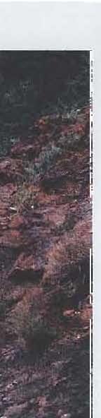
12 Figure 7.1: Crush breccia on the southern strand of the Melinda Fault at 'S; 28 S7.46'E. Note the lack of foliation or amphibolite lenses. Camera bag is 2Scm high. Figure 7.2: Detail of crush breccia at 'S; 28 S7.46'E. Note the lack of cobesion and presence of tbin quartz veins. Lens cap is Scm wide. 228


13 Figure 7.3: Crush breccia showing intense intrusion of quartz veins, which strike parallel to the strike of the southern strand of the Melinda Fault. Recorded at 'S; 28 S7.46'E. Lens cap is Scm wide. Figure 7.4: Low-angled foliation developed on a thrust fault at 'S; 'E. Dip-direction of thrust plane: 100~030. high. G.P.S. receiver is IScm 229


 is")


14 Figure 7.5: Horizontal slickensided surface caused by brittle reactivation in basement gneiss at '8; 'E. Tbe compass (7cm wide) is orientated parallel to the lineation, and shows a trend of tepping on the surface suggests vergence towards the south. Figure 7.8: Folding developed in the Blouberg Formation at '8; 'E. View is approximately eastwards, showing the east-west trending fold axis plotted in Figure 7.9. Rucksack is 50cm high. 230

15 N =23 + = slickenside lineations Figure 7.6: Stereographic projection showing orientation of low-angled thrust fault planes cuttingthe basement gneiss, and the orientation of slickenside lineations developed on some of those surfaces. 231

16 Fold-axis Contour values (%) ~ \ \ \ \ & \ \. \ ~ \ N = 89 = poles to bedding of Lower Member = poles to overturned bedding of Lower Member = poles to bedding of Upper Member 10% 8% 6% 4% 2% Figure 7.7: Stereographic projection showing poles to hedding planes recorded in the Blouberg Formation in the Blouberg mountain area. 232

17 N Contour values (%) 24% 22% 20% 18%!!! Fold-axis ~ 8% 16% 14% 12% 10% 6% 4% 2% I N =8 = Poles of bedding = Poles of overturned bedding Figure 7.9: Stereographic projection showing poles to bedding planes of Blouberg strata at 'S; 2S053.47'E.


.")


18 L"9'~"'T:U~~._~~~ I] Axial planar trace Younging direction Blouberg Fm. Figure 7.10a: Steeply-dipping reverse fault recorded at 'S; 28 s9.43'e, which cuts the Blouberg Formation. Fault plane has a dip-direction ofs2 ~004, and slickenside lineations have an orientation of S2 ~OO4 (Le. dip-slip movement). Weak fabric and stepping on slickenside lineations suggest a vergence to the south. Rucksack is SO em high. Figure 7.l0b: Folded and overturned bedding and reverse fault can be explained by the inferred presence of large-scale southwards-vergent thrust fault above ach portion of overturned bedding. Figure 7 at 'S; 28 ss.2s'e. Dip-direction offault plane is Oso~228, and slickenside lineations are orientated 00~l80. Stepping suggests vergence towards the south. Compass (7cm wide) is orientated north. 234


19 N Fault planes,\~-----,l-~ N = 10 = slickenside lineations Figure 7.11: Stereographic projection showing the orientation of slickenside lineations and some associated fault planes in the Blouberg Formation. 235


20 Figure 7.13: Intense jointing in the lower Wyllies Poort Formation at '8; 'E. Joints strike 010. View looking south. Figure 7.14: striking joint planes developed in the asymmetric rippled planar bedding of the upper Wyllies Poort Formation at '8; 'E (summit ofblouberg mountain). Compass is 6cm wide. 236


 points north, and")
 is 30cm long.")
21 Figure 7.15: Fault developed in the lower strata of the Wyllies Poort Formation at '8; 'E. Fault plane strikes 285, and fabric suggests dextral strike-slip displacement. Needle of compass (7cm wide) points to north. Figure 7.18: Quartz-filled veins intruding the Wyllies Poort Formation at ' 8; 'E. Veins strike 100. Needle of compass (7cm wide) points north, and hammer (in middle ground) is 30cm long. 237

22 S.E. Slickenside lineations 0. 6.' "'~ -z>..",e 'Q... 0;edding-parallel t Flexural slip rn ~ Drag folding Joint planes N.W. Figure 7.16: Sketch showing relationship between bedding-parallel thrust, folded joint planes, and slickenside lineations recorded at 2f' 04.69'S; 2SoS9.49'E. 238

23 ..\ \ \ \,. ZIJ? N Fold axis Contour values (%) 10% 8% 6% 4% \ \ \ 2% N =66 Figure 7.17: Stereographic projection showing the poles to bedding planes in the Wyllies Poort Formation in the vicinity of the northern strand of the Melinda Fault. Fold axis (01 ---,» 066j is shown. 239


24 Figure 7.19: Quartz-filled veins intruding an early brittle fault in the Wyllies Poort Formation at 'S; 'E. Pen is lscm long. Figure 7.20: 140 -striking sinistral dilatational vein (displacement c. 2cm) at 'S; S'E. Needle of compass (7cm wide) points north. 240


25 Figure 7.21: 1.5m wide quartz-filled vein cutting the WyJlies Poort Formation at '8; 'E. Hammer is 30cm long. Figure 7.22: 8mall hill at '8; 'E composed of white quartzite. The northern strand of the Melinda Fault is thought to underlie this area (Appendix 1). 241


")


26 Figure 7.23: East-west striking fault breccia cutting the Wyllies Poort Formation at 'S; 'E. Needle of Compass (7cm wide) points north. Figure 7.24: Fault plane with a dip-direction of 74 ~033 at 'S; 'E, with fault breccia preserved on the fault plane. Pen is 15cm long. 242


27 Figure 7.25: Fault breccia at '8; S'E, with a weak 8-C fabric whicb suggests dextral displacement. Lens cap is Scm wide. Figure 7.30: Pronounced angular unconformity between the overturned Blouberg Formation (bedding plane indicated by lower notebook) and the Mogalakwena Formation above (bedding plane indicated by upper notebook). Recorded at '8; 28 S7.S3'E. 243

28 N N = 39 Figure 7.26: Rose diagram showing the strike of joints in the Wyllies Poort Formation. Principal trend is shown. 244

29 Figure 7.27: Rose diagram to show the strike of veins cutting the Wyllies Poort Formation. Priucipal trend is shown. 245

30 Contour values (%) Figure 7.28: Stereographic projection of poles to fault planes in the Wyllies Poort Formation (associated slickensides are potted in Figure 7.29). 246

31 e 8% Contour values (%) 6% 4% 2% N = 10 Figure 7.29: Stereographic projection showing the orientation of slickenside lineations (associated with fault planes in Figure 7.28) in the Wyllies Poort Formation. 247


32 Figure 7.31: Pronounced angular unconformity between the folded and locally overturned Blouberg Formation and the Mogalakwena Formation above. Recorded at '8; 'E. Note the 1m deep channel developed on the upper surface of the Blouberg Formation to the left of the hammer (30cm long). View taken looking east. Figure 7.32: Pronounced angular unconformity between the overturned B10uberg Formation and the Mogalakwena Formation above, marked by thin basal conglomerate. Recorded at '8; 'E. Cliff section is c. 2m high. 248


 and the Mogalakwena")
. Recorded at 23 11.")

 (with")


33 Figure 7.33: Disconformity (or slight angular unconformity) developed between the Makgabeng Formation (laminated medium-grained sandstone) and the Mogalakwena Formation (cobbles and coarse sandstone). Recorded at '8; 28 S2.44'E. Lens cap is Scm wide. Figure 7.34: Disconformity (or unconformity) between the Makgabeng Formation (with well-developed joint planes) and the Mogalakwena Formation (with no joint planes). Recorded at '8; 28 S2.S7'E. Large pebble in Mogalakwena Formation is 6cm long. 249


34 Figure 7.35: Joint plane in the Makgabeng Formation is exploited as a channel during deposition of the Mogalakwena Formation. Note that joint planes in the Makgabeng Formation are not continuous in the Mogalakwena Formation. Recorded at 'S; 28 S2.S7'E. View is vertical. Lens cap is Scm wide. Figure 7.36: Reduction spot in the upper surface of a small inlier of the Makgabeng Fo, mation is not continuous into coarse grained strata of the Mogalakwena Formation, indicating the onset of diagenetic processes prior to deposition of the Mogalakwena Formation. Recorded at 'S; 28 S2.S7'E. Pen is 15 cm long. 250


35 Figure 7.37: Gentle angular unconformity developed between the Mogalakwena Formation and the Wyllies Poort Formation above. Recorded at 'S; 'E. Cliff section is 100m high. Figure 7.38: Detail of the gentle angular unconformity between the Mogalakwena Formation and the Wyllies Poort Formation above. Recorded at 'S; 'E. Hammer is 30cm long. 251
GLY 155 Introduction to Physical Geology, W. Altermann. Press & Siever, compressive forces. Compressive forces cause folding and faulting.
 Press & Siever, 1995 compressive forces Compressive forces cause folding and faulting. faults 1 Uplift is followed by erosion, which creates new horizontal surface. lava flows Volcanic eruptions cover
LAB 1: ORIENTATION OF LINES AND PLANES
 LAB 1: ORIENTATION OF LINES AND PLANES Read the introductory section, chapter 1, pages 1-3, of the manual by Rowland et al (2007) and make sure you understand the concepts of bearing, strike, dip, trend,
Structural Geology Lab. The Objectives are to gain experience
 Geology 2 Structural Geology Lab The Objectives are to gain experience 1. Drawing cross sections from information given on geologic maps. 2. Recognizing folds and naming their parts on stereoscopic air
Name. GEOL.5220 Structural Geology Faults, Folds, Outcrop Patterns and Geologic Maps. I. Properties of Earth Materials
 I. Properties of Earth Materials GEOL.5220 Structural Geology Faults, Folds, Outcrop Patterns and Geologic Maps Name When rocks are subjected to differential stress the resulting build-up in strain can
Provided by Tasa Graphic Arts, Inc. for An Introduction to Structural Methods DVD-ROM
 Provided by Tasa Graphic Arts, Inc. for An Introduction to Structural Methods DVD-ROM http://www.tasagraphicarts.com/progstruct.html AN INTRODUCTION TO STRUCTURAL METHODS - DETAILED CONTENTS: (Navigate
MEMO. TO: Dennis Lapoint CC: FROM: Eriaan Wirosono DATE: April, 20 th 2014 SUBJECT: Exploration activity report March-April 2014_EW
 TO: Dennis Lapoint CC: FROM: Eriaan Wirosono DATE: April, 20 th 2014 SUBJECT: Exploration activity report March-April 2014_EW MEMO 1. Highlights and Productivity Overview pan sampling on target Areas 1
What Causes Rock to Deform?
 Crustal Deformation Earth, Chapter 10 Chapter 10 Crustal Deformation What Causes Rock to Deform? Deformation is a general term that refers to all changes in the shape or position of a rock body in response
Answers: Internal Processes and Structures (Isostasy)
") Answers: Internal Processes and Structures (Isostasy) 1. Analyse the adjustment of the crust to changes in loads associated with volcanism, mountain building, erosion, and glaciation by using the concept
Answers: Internal Processes and Structures (Isostasy) 1. Analyse the adjustment of the crust to changes in loads associated with volcanism, mountain building, erosion, and glaciation by using the concept
Structural Geology Lab. The Objectives are to gain experience
 Geology 2 Structural Geology Lab The Objectives are to gain experience 1. Drawing cross sections from information given on geologic maps. 2. Recognizing folds and naming their parts on stereoscopic air
Crustal Deformation. (Building Earth s Surface, Part 1) Science 330 Summer Mapping geologic structures
 Science 330 Summer Mapping geologic structures") Crustal Deformation (Building Earth s Surface, Part 1) Science 330 Summer 2005 Mapping geologic structures When conducting a study of a region, a geologist identifies and describes the dominant rock structures
Crustal Deformation (Building Earth s Surface, Part 1) Science 330 Summer 2005 Mapping geologic structures When conducting a study of a region, a geologist identifies and describes the dominant rock structures
UNIVERSITY OF PRETORIA Department of Geology STRUCTURAL GEOLOGY -GLY 254 SEMESTER EXAM
 UNIVERSITY OF PRETORIA Department of Geology STRUCTURAL GEOLOGY -GLY 254 SEMESTER EXAM Copyright reserved 6 th June 2006 Time: 3 hours Internal examiner: Dr A.J. Bumby External examiner: Dr R. van der
State the principle of uniformitarianism. Explain how the law of superposition can be used to determine the relative age of rocks.
 Objectives State the principle of uniformitarianism. Explain how the law of superposition can be used to determine the relative age of rocks. Compare three types of unconformities. Apply the law of crosscutting
Crustal Deformation Earth - Chapter Pearson Education, Inc.
 Crustal Deformation Earth - Chapter 10 Structural Geology Structural geologists study the architecture and processes responsible for deformation of Earth s crust. A working knowledge of rock structures
Stress and Strain. Stress is a force per unit area. Strain is a change in size or shape in response to stress
 Geologic Structures Geologic structures are dynamically-produced patterns or arrangements of rock or sediment that result from, and give information about, forces within the Earth Produced as rocks change
=%REPORT RECONNAISSANCE OF CHISHOLM LAKE PROSPECT. October 25, 1977
 =%REPORT ON FIELD RECONNAISSANCE OF CHISHOLM LAKE PROSPECT October 25, 1977 Bruce D. Vincent Imperial Oil Limited, Minerals - Coal, CALGARY, ALBERTA CHISHOLM LAKE PROSPECT Introduction The Chisholm Lake
Lecture 6 Folds, Faults and Deformation Dr. Shwan Omar
 Fold: A fold is a bend or wrinkle of rock layers or foliation; folds form as a sequence of ductile deformation. Folding is the processes by which crustal forces deform an area of crust so that layers of
Chapter 15 Structures
 Chapter 15 Structures Plummer/McGeary/Carlson (c) The McGraw-Hill Companies, Inc. TECTONIC FORCES AT WORK Stress & Strain Stress Strain Compressive stress Shortening strain Tensional stress stretching
Chapter 10: Deformation and Mountain Building. Fig. 10.1
 Chapter 10: Deformation and Mountain Building Fig. 10.1 OBJECTIVES Describe the processes of rock deformation and compare and contrast ductile and brittle behavior in rocks. Explain how strike and dip
!'f \, w. Alan Stewart Colorado Exploration Company, Golden STRUCTURE OF THE FOOTHILLS AREA WEST OF DENVER, COLORADO. Introduction
 STRUCTURE OF THE FOOTHLLS AREA WEST OF DENVER, COLORADO w. Alan Stewart Colorado Exploration Company, Golden ntroduction i ; The dominant structural features west of Denver and along the mountain front
GEOLOGICAL INVESTIGATION IN THE ISLAND LAKE GREENSTONE BELT, NORTHWESTERN SUPERIOR PROVINCE, MANITOBA (PARTS OF NTS 53E/15 & 16) GS-18
 GS-18") GS-18 GEOLOGICAL INVESTIGATION IN THE ISLAND LAKE GREENSTONE BELT, NORTHWESTERN SUPERIOR PROVINCE, MANITOBA (PARTS OF NTS 53E/15 & 16) by S. Lin, H.D.M. Cameron, E.C. Syme and F. Corfu 1 Lin, S., Cameron,
GS-18 GEOLOGICAL INVESTIGATION IN THE ISLAND LAKE GREENSTONE BELT, NORTHWESTERN SUPERIOR PROVINCE, MANITOBA (PARTS OF NTS 53E/15 & 16) by S. Lin, H.D.M. Cameron, E.C. Syme and F. Corfu 1 Lin, S., Cameron,
Question 1: Examine the following diagram:
 Question 1: Examine the following diagram: 1a.) Which of the illustrated faults is a left-handed strike-slip fault? = a 1b.) Which of the illustrated faults is a normal-slip fault? = e 1c.) Which of the
Answer sheet for question 1 Answer question 1 as soon as the sample arrives at your desk.
 EAS 233 Geologic structures. Final test. April 2012. 3 hours. Answer question 1 and 2 and three other questions. If you start more than the required number of questions, clearly delete the answers you
Geomorphology Final Exam Study Guide
 Geomorphology Final Exam Study Guide Geologic Structures STRUCTURAL GEOLOGY concerned with shapes, arrangement, interrelationships of bedrock units & endogenic (within) forces that cause them. Tectonic
Team Name. Name(s) SSSS Unome Geologic Mapping Test Packet p1
 SSSS Unome Geologic Mapping Test Packet p1") Scioly Summer Study Session 2018-2019 Geologic Mapping Test Packet Written by Unome Instructions 1) This test is based on the 2016 rules for Geologic Mapping. 2) This test is out of 115 points. Questions
Scioly Summer Study Session 2018-2019 Geologic Mapping Test Packet Written by Unome Instructions 1) This test is based on the 2016 rules for Geologic Mapping. 2) This test is out of 115 points. Questions
Evaluation of Structural Geology of Jabal Omar
 International Journal of Engineering Research and Development e-issn: 2278-067X, p-issn: 2278-800X, www.ijerd.com Volume 11, Issue 01 (January 2015), PP.67-72 Dafalla Siddig Dafalla * and Ibrahim Abdel
The importance of both geological structures and mining induced stress fractures on the hangingwall stability in a deep level gold mine
 The importance of both geological structures and mining induced stress fractures on the hangingwall stability in a deep level gold mine by G.B. Quaye and G. Guler* Synopsis The deep level gold mining environment
A. Refer to Appendix F in back of lab manual for list of commonly used geologic map symbols
 Structural Geology Lab 2: Outcrop Patterns and Structure Contours I. Geologic Map Symbols A. Refer to Appendix F in back of lab manual for list of commonly used geologic map symbols 1. Emphasis: a. strike
Continental Landscapes
 Continental Landscapes Landscape influenced by tectonics, climate & differential weathering Most landforms developed within the last 2 million years System moves toward an equilibrium Continental Landscapes
B) color B) Sediment must be compacted and cemented before it can change to sedimentary rock. D) igneous, metamorphic, and sedimentary rocks
 color B) Sediment must be compacted and cemented before it can change to sedimentary rock. D) igneous, metamorphic, and sedimentary rocks") 1. Which characteristic of nonsedimentary rocks would provide the least evidence about the environment in which the rocks were formed? A) structure B) color C) crystal size D) mineral composition 2. Which
1. Which characteristic of nonsedimentary rocks would provide the least evidence about the environment in which the rocks were formed? A) structure B) color C) crystal size D) mineral composition 2. Which
BUREAU OF MINERAL RESOURCES GEOLOGY AND GEOPHYSICS.
 COMMONWEALTH OF AUSTRALIA. DEPARTMENT OF NATIONAL DEVELOPMENT. BUREAU OF MINERAL RESOURCES GEOLOGY AND GEOPHYSICS. RECORDS: 1962/33 GEOLOGY OF THE B.W. IRON CLAIM, HUNDRED OF WATERHOUSE, NORTHERN TERRITORY.
The geology of the Vermont Valley and the western flank of the Green Mountains between Dorset Mountain and Wallingford, Vermont
 University at Albany, State University of New York Scholars Archive Geology Theses and Dissertations Atmospheric and Environmental Sciences 1992 The geology of the Vermont Valley and the western flank
N30 E-45 SE S25 E-10 SW N85 W-80 NE
 Geologic aps and tructures Name Geology 100 Harbor section Read h. 7 before you begin. The objectives of this lab are for you to learn the basic geologic structures in 3- and to develop some facility in
 1-6 Figure 1.3. View of the field area, looking south-southwest. Left side of the picture shows the steep flank of the Green Mountain massif. The Vermont Valley and the Tinmouth Valley are separated by
Site 4.7. Thornhill Drumlin Jane K. Hart
 Site 4.7. Thornhill Drumlin Jane K. Hart Introduction The drumlins in the West of Ireland represent some of the best exposured features in the whole of Britain and Ireland, and have been studied by numerous
TECTONIC AND STRUCTURAL CONTROLS ON INTRUSION- RELATED DEPOSITS IN THE NORTHERN PART OF SREDNA GORA ZONE, BULGARIA NIKOLAY PETROV & KAMELIA NEDKOVA
 TECTONIC AND STRUCTURAL CONTROLS ON INTRUSION- RELATED DEPOSITS IN THE NORTHERN PART OF SREDNA GORA ZONE, BULGARIA NIKOLAY PETROV & KAMELIA NEDKOVA INVESTIGATED AREA Praveshka Lakavica deposit Elatsite
Characteristics and processes associated with the development of Hilly Landscapes
 GRADE 11 GEOGRAPHY SESSION 1: GEOMORPHOLOGY I (TOPOGRAPHY) Key Concepts In this lesson we will focus on summarising what you need to know about: Topography associated with Horizontally Layered Rocks Topography
GEOLOGIC MAPS PART II
 EARTH AND ENVIRONMENT THROUGH TIME LABORATORY - EES 1005 LABORATORY FIVE GEOLOGIC MAPS PART II Introduction Geologic maps of orogenic belts are much more complex than maps of the stable interior. Just
Quaternary clays alluvial sands of the Shepparton Formation overlie the basement rocks.
 NAGAMBIE GOLDFIELD Regional Geological Setting The Nagambie Project is located within the Melbourne Structural Zone of Victoria. The lithologies range in age from the Upper Silurian Broadford Formation
PROCEEDINGS, INDONESIAN PETROLEUM ASSOCIATION Thirty-Ninth Annual Convention and Exhibition, May 2015
 IPA15-SG-089 PROCEEDINGS, INDONESIAN PETROLEUM ASSOCIATION Thirty-Ninth Annual Convention and Exhibition, May 2015 STRUCTURAL INTERPRETATION OF TECTONICALLY ASSOCIATED NORMAL AND REVERSE FAULTS OF BUKIT
General Geology Lab #7: Geologic Time & Relative Dating
 General Geology 89.101 Name: General Geology Lab #7: Geologic Time & Relative Dating Purpose: To use relative dating techniques to interpret geological cross sections. Procedure: Today we will be interpreting
Sediment and sedimentary rocks Sediment
 Sediment and sedimentary rocks Sediment From sediments to sedimentary rocks (transportation, deposition, preservation and lithification) Types of sedimentary rocks (clastic, chemical and organic) Sedimentary
Outcrops from Every Continent and 20 Countries in 140 Contributions. Tor H. Nilsen, Roger D. Shew, Gary S. Steffens, and Joseph R.J. Studlick.
 Paper VIII Tor H. Nilsen, Roger D. Shew, Gary S. Steffens, and Joseph R.J. Studlick Editors Outcrops from Every Continent and 20 Countries in 140 Contributions http://bookstore.aapg.org Length ~ 23 m (75.5
CHAPTER Va : CONTINUOUS HETEROGENEOUS DEFORMATION
 Va-1 INTRODUCTION Heterogeneous deformation results from mechanical instabilities (folding and boudinage) within an heterogeneous material or from strain localization in an homogeneous material (shear
The geology of the B10uberg Formation, Waterberg and Soutpansberg Groups in the area of Blouberg mountain, Northern Province, South Africa
 The geology of the B10uberg Formation, Waterberg and Soutpansberg Groups in the area of Blouberg mountain, Northern Province, South Africa by ADAM JOHN BUMBY Submitted in partial fulfillment of the requirements
Strike-Slip Faults. ! Fault motion is parallel to the strike of the fault.
 Strike-Slip Faults! Fault motion is parallel to the strike of the fault.! Usually vertical, no hanging-wall/footwall blocks.! Classified by the relative sense of motion. " Right lateral opposite block
THE HETEROGENEOUS STRUCTURE OF FAULT ZONES WITHIN CARBONATE ROCKS: EVIDENCE FROM OUTCROP STUDIES AND IMPLICATIONS FOR FLUID FLOW
 THE HETEROGENEOUS STRUCTURE OF FAULT ZONES WITHIN CARBONATE ROCKS: EVIDENCE FROM OUTCROP STUDIES AND IMPLICATIONS FOR FLUID FLOW C.G. Bonson*, J.J. Walsh, C. Childs, M.P.J. Schöpfer & V. Carboni Fault
Earth Science 11: Geologic Time Unit
 Earth Science 11: Geologic Time Unit Text: Chapters 8 Lab: Exercise 6 Name Earth Science 11: Geologic Time Page 1 Geology 12: Geologic Time 8.1: The Geologic Time Scale Today, we know that Earth is approximately
Deep Time: How Old Is Old?
 Deep Time: How Old Is Old? Updated by: Rick Oches, Professor of Geology & Environmental Sciences Bentley University Waltham, Massachusetts Based on slides prepared by: Ronald L. Parker, Senior Geologist
High-resolution Sequence Stratigraphy of the Glauconitic Sandstone, Upper Mannville C Pool, Cessford Field: a Record of Evolving Accommodation
 Page No. 069-1 High-resolution Sequence Stratigraphy of the Glauconitic Sandstone, Upper Mannville C Pool, Cessford Field: a Record of Evolving Accommodation Thérèse Lynch* and John Hopkins, Department
The Geology of Two Lights State Park. Cape Elizabeth, Maine
 Maine Geologic Facts and Localities June, 2002 Cape Elizabeth, Maine 43 33 33.48 N, 70 12 13.32 W Text by Henry N. Berry IV and Robert G. Marvinney, Department of Agriculture, Conservation & Forestry 1
lecture 7 Foliations & lineations
 Kristallingeologie lecture 7 Foliations & lineations 28 participants Results test A, 2008 Maximum 70 points Pass!35 points (!50%) Best result 67 points Average result 54 points ("2.3) Worst result 30 points
As compaction and cementation of these sediments eventually occur, which area will become siltstone? A) A B) B C) C D) D
 A B) B C) C D) D") 1. A student obtains a cup of quartz sand from a beach. A saltwater solution is poured into the sand and allowed to evaporate. The mineral residue from the saltwater solution cements the sand grains together,
1. A student obtains a cup of quartz sand from a beach. A saltwater solution is poured into the sand and allowed to evaporate. The mineral residue from the saltwater solution cements the sand grains together,
GEOLOGY 470 FIELD EXERCISE 3, SPRING SKETCHING, DESCRIBING, AND MAPPING EXPOSURES
 GEOLOGY 470 FIELD EXERCISE 3, SPRING 2009 -- SKETCHING, DESCRIBING, AND MAPPING EXPOSURES 1 OBJECTIVES: To develop and refine your field skills in: 1. observation and rock and sediment description 2. sketching
Structural Geology and Geology Maps Lab
 Structural Geology and Geology Maps Lab Mesa College Geology 101 Lab Ray Rector: Instructor Structural Geology Lab Pre-Lab Resources Pre-Lab Internet Links 1) Fundamentals of Structural Geology 2) Visualizing
GY 112L Earth History
 GY 112L Earth History Lab 2 Vertical Successions and Sequences of Events GY 112L Instructors: Douglas Haywick, James Connors, Mary Anne Connors Department of Earth Sciences, University of South Alabama
Sedimentary Structures in Metamorphic Rocks
 Maine Geologic Facts and Localities November, 2006 Primary Sedimentary Structures in Some Metamorphic Rocks Text by Thomas K. Weddle, Department of Agriculture, Conservation & Forestry 1 Photo by Thomas
The Aïn Kerma Gold Prospect (ONHYM) Tan Tan Province, Guelmin - Es Semara Region, Southern Morocco. Field Visit Report
 Tan Tan Province, Guelmin - Es Semara Region, Southern Morocco. Field Visit Report") The Aïn Kerma Gold Prospect (ONHYM) Tan Tan Province, Guelmin - Es Semara Region, Southern Morocco. Field Visit Report 1. Introduction The field visit took place on Wednesday, the 21 st July. It took place
The Aïn Kerma Gold Prospect (ONHYM) Tan Tan Province, Guelmin - Es Semara Region, Southern Morocco. Field Visit Report 1. Introduction The field visit took place on Wednesday, the 21 st July. It took place
Lecture # 6. Geological Structures
 1 Lecture # 6 Geological Structures ( Folds, Faults and Joints) Instructor: Dr. Attaullah Shah Department of Civil Engineering Swedish College of Engineering and Technology-Wah Cantt. 2 The wavy undulations
7 Sedimentation and tectonics at a mid- Ordovician to Silurian active margin
 80 Mountain Building in Scotland 7 Sedimentation and tectonics at a mid- Ordovician to Silurian active margin 7.1 Introduction In mid-ordovician to Silurian times, the Grampian mountains underwent exhumation,
Geologic Structures. Changes in the shape and/or orientation of rocks in response to applied stress
 Geologic Structures Changes in the shape and/or orientation of rocks in response to applied stress Figure 15.19 Can be as big as a breadbox Or much bigger than a breadbox Three basic types Fractures >>>
sedimentary cover a) marine sediments b) continental sediments depth of crust: 5-10 km
 marine sediments b) continental sediments depth of crust: 5-10 km") Deformation and Brittle Fracture I. Primary Rock Structure A. Tectonic Control of Rock Structure 1. Lithospheric Plates a. plate = crust + upper mantle above asthenosphere (1) Layered Crust (a) oceanic
Deformation and Brittle Fracture I. Primary Rock Structure A. Tectonic Control of Rock Structure 1. Lithospheric Plates a. plate = crust + upper mantle above asthenosphere (1) Layered Crust (a) oceanic
EAS 233 Geologic Structures and Maps Winter Miscellaneous practice map exercises. 1. Fault and separation:
 Miscellaneous practice map exercises 1. Fault and separation: With respect to Map 1, what are (a) the orientation of the fault, and (b) the orientation of bedding in the units cut by the fault. (c) Mark
THEME 8: The Mokolian Era. Namaqualand Metamorphic Complex. This is a granite-gneiss complex. Includes folded and metamorphosed volcanosedimentary
 THEME 8: The Mokolian Era This runs from 2050 Ma (end of Bushveld Complex) to 1080 Ma (start of Pan African) Includes: Namaqualand metamorphic Complex, Natal metamorphic Complex, sedimenatery sequences
Chapter 3. Geology & Tectonics
 Chapter 3 Geology & Tectonics 3.1 Geology The general geological features of Indonesia are shown in Figure 3.1. The basement formation is metamorphic and it is intruded with plutonic formations. They are
CHAPTER 1: INTRODUCTION.
 CHAPTER 1: INTRODUCTION. 1.1: Location of the Study Area: The area investigated in this thesis is situated in the Northern Province of the Republic of South Africa (Figure 1.1). The study area lies approximately
Page 1. Name:
 Name: Questions 1 through 3 refer to the following: The diagrams below represent two rock outcrops found several miles apart in New York State. Individual rock layers are lettered, and fossils and rock
EPS 50 Lab 6: Maps Topography, geologic structures and relative age determinations
 Name: EPS 50 Lab 6: Maps Topography, geologic structures and relative age determinations Introduction: Maps are some of the most interesting and informative printed documents available. We are familiar
GEOLOGY 435 FIELD EXERCISE 2, SPRING SKETCHING, DESCRIBING, AND MAPPING EXPOSURES OBJECTIVES:
 OBJECTIVES: GEOLOGY 435 FIELD EXERCISE 2, SPRING 2016 -- SKETCHING, DESCRIBING, AND MAPPING EXPOSURES To develop and refine your field skills in: 1. observation and rock and sediment description 2. sketching
GCE AS/A level 1211/01 GEOLOGY GL1 Foundation Unit
 Surname Centre Number Candidate Number Other Names 2 GCE AS/A level 1211/01 GEOLOGY GL1 Foundation Unit S15-1211-01 A.M. MONDAY, 11 May 2015 1 hour For s use Question Maximum Mark 1. 15 2. 14 Mark Awarded
Seismic stratigraphy, some examples from Indian Ocean, interpretation of reflection data in interactive mode
 Seismic stratigraphy, some examples from Indian Ocean, interpretation of reflection data in interactive mode K. S. Krishna National Institute of Oceanography, Dona Paula, Goa-403 004. krishna@nio.org Seismic
3. GEOLOGY. 3.1 Introduction. 3.2 Results and Discussion Regional Geology Surficial Geology Mine Study Area
 3. GEOLOGY 3.1 Introduction This chapter discusses the baseline study of the geology and mineralization characteristics of the mine study area. The study consolidates existing geological data and exploration
Lecture 9 faults, folds and mountain building
 Lecture 9 faults, folds and mountain building Rock deformation Deformation = all changes in size, shape, orientation, or position of a rock mass Structural geology is the study of rock deformation Deformation
Interactive 3D Sketchupbook
 THE UNIVERSITY OF SYDNEY - SCHOOL OF GEOSCIENCES Interactive 3D Sketchupbook Patrice F. Rey CHAPTER 1 Orienting Planes and Lines 1 Interactive 1.1 Strike, dip and dip direction In a 3D space, planar surfaces
Data Repository item
 Data Repository (B25407): Localities and descriptions of measured sections of study areas Table 1. Localities of the measured sedimentary sections in the NW Sichuan Basin Section Number Stratigraphy Locality
Faults, folds and mountain building
 Faults, folds and mountain building Mountain belts Deformation Orogens (Oro = Greek all changes for mountain, in size, shape, genesis orientation, = Greek for or formation) position of a rock mass Structural
lecture 8 Methods of Structural Geology This lecture Mas Rabassers de Dalt (Spain) Mas Rabassers de Dalt (Spain)
 Mas Rabassers de Dalt (Spain)") This lecture Methods of Structural Geology lecture 8 Discuss the plotting exercise on Mas Rabassers de Dalt Look at folding related to shear zones Show an example of the application of new theory: Cap
This lecture Methods of Structural Geology lecture 8 Discuss the plotting exercise on Mas Rabassers de Dalt Look at folding related to shear zones Show an example of the application of new theory: Cap
Summary. Introduction. Observations and Interpretations
 Lower McMurray Formation sinkholes and their fill fabrics: effects of salt dissolution collapse-subsidence across the northern Athabasca oil sands deposit Paul L. Broughton, Chevron Canada Resources, Calgary,
The Kingfisher Field, Uganda - A Bird in the Hand! S R Curd, R Downie, P C Logan, P Holley Heritage Oil plc *
 A Bird in the Hand! EXTENDED ABSTRACT The Kingfisher Field, Uganda - A Bird in the Hand! Heritage Oil plc * The Kingfisher Field lies on Uganda s western border beneath Lake Albert, situated in the western
Appendix 11. Geology. of the. I60 area
 Appendix 11 Geology of the I60 area 1. Locality The locality of the I60 area is as follows; Northwestern corner; UTM_EW 530513, UTM_NS 7345741 Southwestern corner; UTM_EW 530418, UTM_NS 7301454 Northeastern
PRINCETON BASIN (92H/7E, 8W. 9W, 10E)
") PRINCETON BASIN (92H/7E, 8W. 9W, 10E) By R. D. McMechan INTRODUCTION Remapping of the Princeton basin, south-central British Columbia, was undertaken during the summer of 1975 in order to: (1) produce
PRINCETON BASIN (92H/7E, 8W. 9W, 10E) By R. D. McMechan INTRODUCTION Remapping of the Princeton basin, south-central British Columbia, was undertaken during the summer of 1975 in order to: (1) produce
Deformation of Rocks. Orientation of Deformed Rocks
 Deformation of Rocks Folds and faults are geologic structures caused by deformation. Structural geology is the study of the deformation of rocks and its effects. Fig. 7.1 Orientation of Deformed Rocks
Distortion Effects of Faults on Gravity Worm Strings Robin O Leary
 Distortion Effects of Faults on Gravity Worm Strings Robin O Leary Problem Can upward continued gravity anomaly worm strings be used as a tool to determine the dip direction of an offsetting structure
Bradbury Mountain, Pownal, Maine
 Maine Geologic Facts and Localities August, 2008 Bradbury Mountain, Pownal, Maine 43 o 53 56.56 N, 70 o 10 45.11 W Text by Henry N. Berry IV, Department of Agriculture, Conservation & Forestry 1 Introduction
Blocks Module Content Guide
 Blocks Module Content Guide This guide covers the basics of the content within the Interactive 3D Geologic Blocks Module. The content guide is intended to assist you, the teacher, in creating effective
Landforms and Rock Structure
 Landforms and Rock Structure Rock Structure as a Landform Control Landforms of Horizontal Strata and Coastal Plains Landforms of Warped Rock Layers Landforms Developed on Other Land-Mass Types Landforms
NMBGMR Geologic Map Symbols
 NMBGMR Geologic Map Symbols LINES: Exposure Exposed Intermittent/Obscured Concealed Certain (or unspecified) Geologic contact, fault, or fold, exposed with high positional accuracy. Triangle shows location
Geology Stratigraphic Correlations (Lab #4, Winter 2010)
") Name: Answers Reg. lab day: Tu W Th Geology 1023 Stratigraphic Correlations (Lab #4, Winter 2010) Introduction Stratigraphic correlation is the process of comparing rocks at one locality with related rocks
Name: Answers Reg. lab day: Tu W Th Geology 1023 Stratigraphic Correlations (Lab #4, Winter 2010) Introduction Stratigraphic correlation is the process of comparing rocks at one locality with related rocks
A.M. TUESDAY, 12 May hours
 Candidate Name Centre Number 2 Candidate Number GCE AS/A level 1212/01 New AS GEOLOGY - GL2a Investigative Geology A.M. TUESDAY, 12 May 2009 1 1 2 hours For Examiner s Use Only ADDITIONAL MATERIALS In
Why is quartz one of the most weathering-resistant minerals?
 Why is it a poor idea to use limestone for tombstones in a wet hot area like the Amazon rainforest? A) Because limestone weathers at a very fast rate B) Because limestone weathers at a very low rate C)
Supplementary Material
 GSA Data Repository item 2018118 Brardinoni, F., Picotti, V., Maraio, S., Paolo Bruno, P., Cucato, M., Morelli, C., and Mair, V., 2018, Postglacial evolution of a formerly glaciated valley: Reconstructing
In this lab, we will study and analyze geologic maps from a few regions, including the Grand Canyon, western Wyoming, and coastal California.
 Name: Lab Section: work in groups, but each person turns in his/her own GEOSCIENCE 001 LAB UNDERSTANDING GEOLOGIC MAPS Geologic maps are colorful and even beautiful, but they also contain an amazing amount
Downloaded from Downloaded from
 IV SEMESTER BACK-PAPER EXAMINATION-2004 Q. [1] [a] Describe internal structure of the earth with a neat sketch. Write down the major land forms and their characteristics on the earth surface. [8] [b] What
Structural Evolution of the Keno Hill Ag-Pb-Zn mining district, Yukon
 Structural Evolution of the Keno Hill Ag-Pb-Zn mining district, Yukon Simon D. Craggs, David R. Lentz and Joseph C. White Introduction The Keno Hill Ag-Pb-Zn mining district is located in the central Yukon,
GEOLOGY MEDIA SUITE Chapter 8
 UNDERSTANDING EARTH, SIXTH EDITION GROTZINGER JORDAN GEOLOGY MEDIA SUITE Chapter 8 Clocks in Rocks Timing the Geologic Record 2010 W.H. Freeman and Company Stratigraphy and fossils Figure 8.4 (page 172)
"When Gregor Samsa woke up one morning from unsettling dreams, he found himself changed into a monstrous bug. Metamorphosis, by Franz Kafka
 Metamorphosis "When Gregor Samsa woke up one morning from unsettling dreams, he found himself changed into a monstrous bug. Metamorphosis, by Franz Kafka Metamorphism The transformation of rock by temperature
Structural Deformation and Karst in the Devonian Waterways Formation: Examples from Outcrops along the Athabasca River*
 Structural Deformation and Karst in the Devonian Waterways Formation: Examples from Outcrops along the Athabasca River* Chris L. Schneider 1 and Matthias Grobe 2 Search and Discovery Article #51073 (2015)
KEY CHAPTER 12 TAKE-HOME QUIZ INTERNAL STRUCTURES AND PROCESSES Score Part B = / 55 PART B
 GEOLOGY 12 KEY CHAPTER 12 TAKE-HOME QUIZ INTERNAL STRUCTURES AND PROCESSES Score Part B = / 55 PART B CHAPTER 12 Isostacy and Structural Geology 1. Using the terms below, label the following diagrams and
Satulinmäki Au Prospect Structural Mapping
 M19/2024/2003/1/10 Juhani Ojala Satulinmäki Au Prospect Structural Mapping V. Juhani Ojala Geological Survey of Finland 1 Table of Contents Introduction...2 Local geology...2 Structures...2 Discussion...2
Structural Geology, GEOL 330 Fold mapping lab: Even folds get parasites Spring, 2012
 Structural Geology, GEOL 330 Name: Fold mapping lab: Even folds get parasites Spring, 2012 This exercise is meant to mimic a field experience in which you, the student, will measure beddingcleavage relationships
depression above scarp scarp
 1 LAB 1: FIELD TRIP TO McKINLEYVILLE AND MOUTH OF THE MAD RIVER OBJECTIVES: a. to look at geomorphic and geologic evidence for large scale thrust-faulting of young sediments in the Humboldt Bay region