Clones Public Water Supply Scotshouse Boreholes
|
|
|
- Aubrie Francis
- 5 years ago
- Views:
Transcription
1 Clones Public Water Supply Scotshouse Boreholes Groundwater Source Protection Zones Prepared by: Melissa Swartz Geological Survey of Ireland Assisted by: Donal Daly, Geological Survey of Ireland Vincent Fitzsimons, Geological Survey of Ireland Kieran O Dwyer, Kevin Cullen and Co., Ltd. In collaboration with: Monaghan County Council September 2002
2 TABLE OF CONTENTS 1 INTRODUCTION LOCATION, SITE DESCRIPTION AND WELL HEAD PROTECTION SUMMARY OF WELL DETAILS METHODOLOGY DESK STUDY SITE VISITS AND FIELDWORK ASSESSMENT TOPOGRAPHY, SURFACE HYDROLOGY AND LAND USE GEOLOGY INTRODUCTION BEDROCK GEOLOGY SUBSOIL GEOLOGY Alluvium Peat Till (Boulder Clay) Tills with Gravel Depth to Bedrock HYDROGEOLOGY INTRODUCTION METEOROLOGY AND RECHARGE GROUNDWATER LEVELS, FLOW DIRECTIONS AND GRADIENTS AQUIFER CHARACTERISTICS AQUIFER CATEGORY Coronea Formation Fearnaght Sandstones Cooldaragh Limestones Ulster Canal Limestones Ballysteen Limestones HYDROCHEMISTRY AND WATER QUALITY CONCEPTUAL MODEL DELINEATION OF SOURCE PROTECTION AREAS OUTER PROTECTION AREA INNER PROTECTION AREA VULNERABILITY GROUNDWATER PROTECTION ZONES POTENTIAL POLLUTION SOURCES CONCLUSIONS AND RECOMMENDATIONS REFERENCES...13
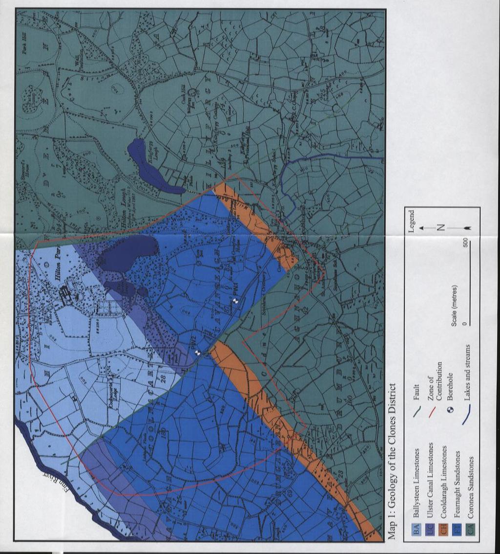
3 LIST OF FIGURES Figure 1 Drawdown vs. Time graphs for the Scotshouse Boreholes Map 1 Bedrock geology of the Scotshouse Area Map 2 Groundwater vulnerability zones at the Clones (Scotshouse) Source Map 3 Groundwater Source Protection Zones at the Clones (Scotshouse) Source LIST OF TABLES Table 1 Bedrock Geology of the Scotshouse Area Table 2 Summary of Pumping Test Calculations Table 3 Summary of Hydrochemistry Data for Pumping Wells 1 and 2 Table 4 Summary of Source Protection Zones at the Scotshouse Source
4 1 Introduction The two boreholes at Scotshouse are used to supply the Clones Public Water Supply. The objectives of the report are as follows: To delineate source protection zones for Scotshouse boreholes. To outline the principal hydrogeological characteristics of the Scotshouse area. To assist Monaghan County Council in protecting the water supply from contamination. 2 Location, Site Description and Well Head Protection The two boreholes are located near Scotshouse, approximately 0.4 km and 0.8 km respectively, north west of Scotshouse village and represent the groundwater portion of the source that supplies the people of Scotshouse and Clones. The two boreholes were drilled in Both wells are 70 m deep and are lined with steel casing to bedrock, after which they are unlined to the bottom of the hole. The boreholes are situated in lay-bys, off a minor road leading out of Scotshouse. Observation wells are located within 5 m of each borehole. With the exception of one observation well, the boreholes have been welded closed with a metal plate, as they are not yet in production. The County Council expects to install the pumps in the summer of Summary of Well Details Grid ref. (1:50,000) : 24881E; 31982N Townland : Cavanreagh Well type, name : Borehole, PW1 Owner : Monaghan County Council Elevation (ground level) : 50 m OD Depth of borehole : 70 m below ground level Diameter of borehole : 300 mm Depth to rock : 9.5 m Static water level : 0.9 m (16 April 1998) Pumping water level : Not yet established Planned abstraction rate : 360 m/d 3 Pumping Test Summary: (i) Abstraction rate: 1221 m/d 3 (ii) Drawdown: 27 m (at end of test) (iii) Transmissivity: 80 m 2 /d Grid ref. (1:50,000) : 24850E; 32047N Townland : Cavanreagh Well type, name : Borehole, PW2 Owner : Monaghan County Council Elevation (ground level) : 50 m OD Depth of borehole : 70 m below ground level Diameter of borehole : 300 mm Depth to rock : 5 m bgl Static water level : 1.1 m bgl (16 April 1998) Pumping water level : Not yet established. Planned abstraction rate : 540 m/d 3 Pumping Test Summary: (i) Abstraction rate: 917 m/d 3 (ii) Drawdown :16 m (at end of test) (iii) Transmissivity : m 2 /d 1
5 The pumping test data analysed are from 4-week pumping tests carried out by K.T. Cullen and Company (KTC) in June Both boreholes were pumped simultaneously and water levels were monitored in six wells during the course of the test. 4 Methodology 4.1 Desk Study Details about the boreholes such as elevation and abstraction figures were obtained from GSI records and County Council personnel; geological and hydrogeological information was provided by the GSI and the various hydrogeologic reports by KTC. Additional information regarding the hydrogeology of the area was gained through a meeting with Kieran O Dwyer of KTC in August Site visits and fieldwork This included carrying out depth to rock drilling, subsoil sampling and vulnerability mapping. Field walkovers were also carried out to investigate the subsoil geology, the hydrogeology and vulnerability to contamination. 4.3 Assessment Data analyses incorporated field studies and previously collected data to delineate protection zones around the sources. 5 Topography, Surface Hydrology and Land Use The boreholes are located to the north west of Scotshouse, on the edge of Hilton Park. The boreholes are located in a small river valley that drains Killyfargy Lough and Hilton Lough towards the Finn River. The Finn River is the primary surface water feature in the area, flowing southwest. The overall topography in the area is hilly due to the large number of drumlins in the region. Agriculture and the village are the main activities in the area. There are a few farmyards within 500 m of the boreholes, and it is known that organic wastes are applied to the fields adjacent to PW1. 6 Geology 6.1 Introduction This section briefly describes the relevant characteristics of the geological materials that underlie the Scotshouse area. This provides a framework for the assessment of groundwater flow and source protection zones that will follow in later sections. Bedrock information was taken from a variety of sources including: GSI publication on the bedrock geology of the region (Geraghty et al, 1997) Hydrogeological reports and borehole logs from KTC A geophysical investigation performed by KTC. Subsoils information was gathered from Quaternary geology maps from the 1950 s, and from vulnerability mapping by GSI field personnel in Bedrock Geology The area around the Scotshouse boreholes is underlain by Lower Palaeozoic dirty sandstones and Carboniferous limestones, sandstones and siltstones. The limestones that the boreholes are drilled into are commonly known as the Lower Limestones. The Lower Limestones overlie the Lower Palaeozoic bedrock, and are found in a northeast-southwest band from Monaghan to Killeshandra in 2
6 County Cavan. Along this band, the contact between the Lower Limestones and the Lower Palaeozoic rocks is offset by a series of northwest-southeast trending faults. Two such faults are thought to be located to the east and west of the boreholes. Thus, the boreholes lie within an area of faulted limestones, sandstones and siltstones that are surrounded on the south, east and west by Lower Palaeozoic mudstones, shales and dirty sandstones. Specifically, the boreholes lie within the Cooldaragh Formation. A summary of the different bedrock types found in the area is provided below in Table 1. Table 1: Bedrock Geology of the Scotshouse area. Age Geological Name Geological Description Thickness (m) L Ballyshannon Limestones (BS) Limestones and silty shales at base of unit with C o pale grainstones at top of unit 560 A R B O N I F E R O U S w e r L i m e s t o n e s Basal Clastics Drumgesh Shales (DH) Ballysteen Limestones (BA) Ulster Canal Limestones (UC) Cooldaragh Limestones (CH) Fearnaght Sandstones (FT) Fossiliferous shales with minor limestones to poorly fossiliferous, muddy limestones with minor shale beds Clean sandy or silty limestones at base of unit grading into a muddy fine grained limestone Silty and sandy limestones, some fine grained limestones Pale brown-grey siltstones and mudstones; algal, evaporitic and fine grained limestones; muddy siltstones N/A Pale conglomerate and red sandstone ~20 ORDOVICIAN (LOWER PALAEOZOIC) Coronea Sandstones (CA) Muddy sandstone, red shale, minor volcanic 1,600-2,300 Descriptions of rock units and details of the overall relationship between the Lower Palaeozoic and Carboniferous rocks are largely derived from a GSI report on the area (Geraghty et al., 1997). Borehole logs and geophysical information provided by the KTC reports indicated that the original boundaries shown on the GSI s bedrock geology map are incorrect. Therefore, we redrew the boundaries using the borehole logs, geophysical results and consultations with the GSI s bedrock section. Specifically, the eastern fault is based on the original geology map and the geophysical investigation. While the geophysical information indicates where the fault is, the exact location has not been confirmed by boreholes. The location of the different limestone units, and the boundary between the Fearnaght Sandstones and the Coronea Limestones is based primarily on the borehole logs from KTC reports. A map showing the geology of the area is provided as Figure Subsoil Geology The subsoils in Monaghan were mapped in the 1950 s by Mike O Meara of the GSI. A drilling programme (4 holes) and permeability mapping carried out by the GSI provided additional information on the subsoils. The subsoils comprise a mixture of coarse and fine-grained materials, namely alluvium, peat, tills, and tills with gravel. The distribution of subsoils and depth to rock data are shown in Figure 2. Logs from the boreholes drilled by the GSI are given in Appendix 1. The characteristics of each category are described briefly in the following sections Alluvium This material is found in the lowlying area between Hilton Lough and Production Well 2. Borehole logs from the installation of the well and from the GSI drilling program indicate that the alluvium near PW2 is just under 5 m thick and is a fine-grained, blue-black, smooth CLAY. 3
7 6.3.2 Peat Deposition of peat occurred in post-glacial times with the onset of warmer and wetter climatic conditions. Peat is an unconsolidated brown to black organic material comprising a mixture of decomposed and undecomposed plant matter which has accumulated in a water logged environment. It has an extremely high water content averaging over 90% by volume. In the source area, peat is found in the lowlying areas across the road from PW1, and along the small stream between PW1 and PW Till (Boulder Clay) Till is an unsorted mixture of coarse and fine materials lain down by ice. Tills are the dominant subsoil type in the locality and comprise most of the drumlins (elongated hills) around the borehole. These tills are generally dark brown to dark grey sandy CLAY with frequent to abundant gravels. The gravel sized fragments are usually striated, angular to subangular, dark blue limestone fragments ranging from 1 cm to 3 cm Tills with Gravel Tills with Gravel is a term used to indicate areas where subsoils are a mix of gravels and tills. Depending on the depositional environment, these deposits may be stratified, or comprised predominantly of one material with lenses of the other. Tills with Gravels are located to the north and east of PW1. A GSI borehole drilled in the field adjacent to PW1 indicates the subsoils are silty GRAVEL (TILL), with the gravel fragments being subangular to subrounded, dark blue limestone fragments ranging from 1-5 cm. In one borehole, a thin (~20 cm thick) layer of till may have been encountered; however, sample material was not recovered from the borehole. While PW1 is located in this unit, the borehole log indicates that the subsoils are quite different. A GSI borehole drilled adjacent to PW1 shows approximately 6 m of grey-brown, silty fine SAND with few to no gravels. Because so little gravel is present, it is difficult to tell if this sample is glaciofluvial or till. The sand is underlain by approximately 4.5 m of grey, very dense sandy CLAY (TILL) Depth to Bedrock The drilling programme (4 holes) was carried out to ascertain the depth, thickness and permeability of the subsoils. Using this information and knowledge of sites that have rock cropping out, the depth to rock is estimated across the area. The borehole locations and spot depth to rock locations are shown in Figure 2. The depth to bedrock varies between 3 and 10 m, with the thicker deposits corresponding with the drumlins. 7 Hydrogeology 7.1 Introduction This section presents our current understanding of groundwater flow around the Clones boreholes. These interpretations and conceptualisations of flow are used to delineate source protection zones around the source. Hydrogeological and hydrochemical information for the study was obtained from the following sources: Four-week pumping test performed by K.T. Cullen & Co. in April-May A local, one-day hydrogeological mapping survey carried out by the GSI. A drilling programme and permeability mapping carried out by GSI to ascertain depth to bedrock and subsoil permeability. GSI files and archival Monaghan County Council data. Discussions with KTC in August Water quality test results from samples collected during the pumping tests. 4
8 7.2 Meteorology and Recharge The term recharge refers to the amount of water replenishing the groundwater flow system. The recharge rate is generally estimated on an annual basis, and generally assumed to consist of the input (i.e. annual rainfall) less water losses prior to entry into the groundwater system (i.e. annual evapotranspiration and runoff). The estimation of a realistic recharge rate is critical in source protection delineation, as it dictates the size of the zone of contribution to the source. In areas where point recharge from sinking streams and other karst features do not play a role, the main parameters involved in recharge rate estimation are annual rainfall, annual evapotranspiration, and annual runoff and are listed as follows: Average Annual Rainfall: Calculated to be 948mm yr -1. Rainfall data are from Met Eireann average annual rainfall values for at the Redhills station (Met Eireann, 1996). Annual Evapotranspiration: Estimated at 416mm yr -1. Potential evaporation (P.E.) is estimated to be 438mm yr -1. P.E. data are from a synoptic weather station located in Clones, and are averaged over the years Actual evapotranspiration (A.E.) is then estimated as 95% of P.E. Potential Recharge: Calculated at 532 mm yr -1. Potential Recharge is calculated by subtracting the estimated evapotranspiration from the average annual rainfall. It represents an estimation of the excess soil moisture available for either vertical downward flow to groundwater, or lateral flow through soil and overland flow to surface water. Estimated Actual Recharge: Estimated Actual Recharge represents the amount of water that will infiltrate to groundwater. This is an estimation of recharge which allows for surface water outflow, particularly during periods of heavy rainfall. It roughly estimates the amount of groundwater available to each well. An infiltration rate of 70% was assumed for the tills with gravel, since it is a stratified unit with the gravels being of moderate permeability (10% silt and clay). The NERDO report provides an infiltration rate of 26% for tills in the Clones area (An Foras Forbartha and GSI, 1981). We have applied this figure to the tills, which are assumed to have a low permeability. This infiltration rate may be slightly high in view of the low permeability nature of the subsoils; on the other hand, it is possible that additional recharge may be induced from the streams and lakes in the area. However, this is unlikely since the alluvium is a CLAY, and the hydraulic connection between the ground and surface waters is expected to be poor. Zero infiltration was assumed for the peat and alluvium. 7.3 Groundwater Levels, Flow Directions and Gradients Besides the supply boreholes and the associated observation wells, there are two other wells located within 200 m of the supply boreholes. One well is the existing group scheme well; the second is a domestic well. Recent water level data are not available for the boreholes; therefore water levels recorded at the start of the 4-week pumping test were compared with stream water levels measured in June The water table is generally assumed to be a subdued reflection of topography. The topography in the Scotshouse area is hilly, due to the number of drumlins in the area. The River Finn lies to the northwest of Scotshouse, with small tributaries that drain Killyfargy and Hilton Loughs running near the boreholes. A comparison of stream and borehole water levels shows a difference of 1 m between the two. It is possible that groundwater discharges to these smaller streams, however, it is most likely that the Finn River is the primary groundwater discharge area. Thus, flow are expected to be towards the northwest and in general, perpendicular to contour lines, but will not be influenced by drumlins. The groundwater gradient during pumping, and over a distance of 250 m, is estimated from a MODFLOW model to be 0.03 around PW1 and 0.01 around PW2. 5
9 7.4 Aquifer Characteristics The data used in this section are based on test pumping undertaken by K.T. Cullen and Company in June Four-week constant discharge tests were run in June 1998, simultaneously testing both boreholes. The discharge in PW1 averaged 1221 m/d 3 for the first four days of the test, after which it dropped to 1172 m/d 3. The average discharge in PW2 for the duration of the test was 917 m/d 3. Information gained from the pumping tests, such as drawdown, specific capacity and transmissivities are summarised in Table 2. Drawdown vs. time graphs for each borehole are provided as Figure 1. Table 2: Summary of Pumping Test Calculations Well Average Discharge (m 3 /d) Drawdown (m) Specific Capacity (m 3 /d/m) Transmissivity (m 2 /d) PW PW Notes: Pumping test data were analysed using the Jacob straight-line method. The Scotshouse boreholes are located in the Cooldaragh Limestones, which are predominantly limestones but contain some silt and mudstones. The borehole log shows that PW1 intersects one discreet fracture, while PW2 intersects a number of fractures and layer of fine-grained sandstone. In this area, the limestones are bound to the west and east by faults, which juxtaposes them against Lower Palaeozoic dirty sandstones. These Lower Palaeozoic rocks have a low permeability do not generally provide substantial supplies of water. Figure 1 shows a graph of the drawdown vs. time for PW1 and the associated observation well during the 4-week pumping test. An increase in the rate of drawdown is seen at 1,000 minutes (0.7 days), potentially indicating a barrier condition. An alternative possibility for this change in rate of drawdown may be due to dewatering of the till with gravel subsoils, which leak water into the aquifer. However, the former is the more likely reason. Since the data after 1,000 minutes is indicative of the effect the barrier has on the well, this data is not representative of the aquifer. Transmissivity calculations for PW1 are based on the pumping test results between 10 and 1,000 minutes; and give a result of 80 m 2 /d. Aquifer permeability is estimated as 2.4 m/d. A plot of drawdown vs. time for PW2 and the associated observation well from the 4-week pumping test is also included in Figure 1. Towards the end of the test, at approximately 20,000 minutes (14 days), the rate of drawdown in the pumping well appears to increase even while the rate of drawdown in the observation borehole decreases. Rainfall records provided by Met Eireann from the Clones station show a rainfall event did occur at approximately this time, which explains the decrease in rate of drawdown in the observation borehole. However, this rainfall event is only slightly reflected in PW2. The increase in the rate of drawdown at the end of the pumping test is not understood. Long term pumping data are needed to indicate whether this change in rate of drawdown is significant. Therefore, transmissivity and permeability calculations for PW2 are based on pumping test results from between 10 and 20,000 minutes, and give values of 420 m 2 /d and 7.5 m/d respectively. While these figures cannot be taken as definitive values for the aquifer itself, they do indicate that the transmissivity and permeability of the aquifer in the immediate vicinity of the boreholes, especially PW2, is relatively high. 6
10 Scotshouse (PW1) 4 Week Pump Test Time (min) Figure 1 Drawdown vs. Time graphs for the 4-week pumping tests conducted by KTC. Pumping well data are shown as closed triangles, observation well data are shown as crosses, and discharge data are shown as open circles. 7
11 7.5 Aquifer Category Available hydrogeological information was compiled for the different bedrock types found in the Clones/Scotshouse area to analyse the potential productivity of each unit. Information on the specific well information available in each unit is summarised in Swartz and Daly (2000). A summary of each bedrock unit is provided in the section below, and the aquifer map of the area is shown in Figure Coronea Formation The Lower Palaeozoic rocks in the Clones/Scotshouse area contain few wells with yields above 40 m/d 3. Based on the available well details, the lithology and information from other counties, the Coronea Formation is provisionally classed as a poor aquifer that is generally unproductive except for local zones (Pl) Fearnaght Sandstones The Fearnaght unit is the sandstone and conglomerate rocks that forms the basal member of the Lower Limestones. Little well information is available for the Fearnaght Formation; however, one trial well drilled by KTC in 1996 provided a yield greater than 400 m/d 3, and a specific capacity of 56. Based on the borehole log for this trial well and the information available, the Fearnaght Formation is provisionally classified as a moderately productive aquifer (Lm) Cooldaragh Limestones The two public supply boreholes and the group scheme borehole are located in this unit, and have high yields (>350 m/d 3 ). Two other wells located in the Cooldaragh Limestones provide yields of between m/d 3. Based on these yields and level of fracturing indicated in the borehole logs, this unit is provisionally classified as a regionally important fissured aquifer (Rf). It is worth mentioning that evaporite lenses are associated with the Cooldaragh Limestones, which may result in high levels of sulphate in the groundwater Ulster Canal Limestones No well information is currently available for the Ulster Canal Limestones; however, considering that it has a similar lithology to the Cooldaragh Limestones, this unit is provisionally classified as a moderately productive aquifer (Lm) Ballysteen Limestones Compiled well information indicates that well yields in the Ballysteen Limestones in the Clones area generally fall between m 3 /d. Analysis of well information from the Ballysteen around Monaghan show similar yields. Based on the existing data and lithologic descriptions, the Ballysteen Limestones are provisionally classed as a regionally important fissured aquifer (Rf). 7.6 Hydrochemistry and Water Quality Samples for water quality analysis were collected by KTC during the 4-week pumping test in Each well was sampled four times during the pumping test, although every parameter was not necessarily analysed for each time. These data are tabulated in Table 3, and are summarised below. 8
12 Table 3: Summary of Hydrochemistry Data for Pumping Wells 1 and 2 Parameter Units MAC Value PW1 PW2 20 Apr Apr 98 5 May May Apr Apr 98 5 May May 98 Colour Hazen Turbidity N.T.U ph Conductivity µs/cm Hardness CaCO 3 mg/l Alkalinity CaCO 3 mg/l Sulphate SO 4 mg/l Chloride Cl mg/l Nitrate NO 3 mg/l Nitrite NO 2 mg/l Ammonia NH 4 mg/l Copper Cu µg/l 500 <10 <10 Iron Fe µg/l Manganese Mn µg/l Aluminium Al mg/l 0.2 <0.02 <0.02 Phosphorous P205 µg/l Fluoride F µg/l Suspended Solids mg/l No Visible Lead Pb µg/l <0.8 Odour Dilution No. 2/12 DegC Sulphide Total Coliforms no./100 ml <1 Nil Nil Nil Nil Nil Nil 1 Nil Faecal Coliforms no./100 ml <1 Nil Nil Nil Nil Nil Nil Nil Nil 9
13 The groundwater samples indicate that the groundwater is hard to very hard with total hardness values of mg/l CaCO 3 for PW1 and mg/l CaCO 3 for PW2. This indicates that the groundwater has a hydrochemical signature of a calcium bicarbonate type water. These values are typical of groundwater from a limestone source. The levels of iron and manganese are above the EU MAC value in both boreholes. These are most likely derived from the bedrock, and indicate reducing conditions. Electrical conductivity values are indicative of limestone bedrock, and are higher in PW2. This may indicate that PW2 is drawing water from either the adjacent fault or a different rock unit. The levels of ammonium (NH 4 ) are above the EU MAC value in PW2. New wells sometimes have high ammonium levels, although they typically drop during pumping. These high levels of ammonia indicate reducing conditions, which may be due to the rock type. However, high ammonium levels can also indicate organic waste pollution. Chloride concentrations range from mg/l. Chloride is a constituent of organic wastes and levels higher than 25 mg/l may indicate significant contamination. Concentrations higher than 30 mg/l usually indicate significant contamination has occurred. Thus, the chloride levels give no rise for concern at the Scotshouse boreholes. The suspended solids are above the EU MAC value in both wells, which is not suprising since the wells are new. If the water samples were not filtered prior to analysis, these suspended solids may explain the high concentrations of iron and manganese. A sulphide smell was reported in the last sample from PW2. Both wells are located in the Cooldaragh Formation, which is known to have evaporitic lenses that give rise to high sulphate concentrations. Sulphate levels were below the EU MAC value for all samples. One count of total coliforms was detected in PW2 in the third week of pumping. No faecal coliforms were detected in the samples from either well. Total coliforms may result from naturally occurring bacteria. 7.7 Conceptual Model The planned abstraction rates for supply wells PW1 and PW2 are 360 and 540 m 3 /d respectively. The groundwater regime in the area is complex due to the structural history of the rocks and the available hydrogeological information does not allow a definitive understanding of the hydrogeology. The boreholes lie in a faulted wedge of limestone that is bounded on the east and west by faults, and is juxtaposed against much less permeable rocks. Groundwater flow is primarily controlled by faults and fractures in the bedrock. The overall direction of groundwater flow is towards the streams and rivers. Borehole logs and pumping test data from trial wells in the area indicate that the majority of groundwater supplying the wells comes from the Cooldaragh and Fearnaght units. Very little groundwater is expected to come from the Coronea Formation. The pumping test results from PW1 suggest that groundwater abstraction in the immediate area is reduced by the low permeability rocks west of the boundary fault. An increase in the rate of drawdown occurred near the end of the pumping test at PW2. Without long term pumping data, it is not known whether this change in rate of drawndown is significant. An infiltration rate of 70% was assumed for the Tills with Gravel, while an infiltration rate of 26% was assumed for the tills, and zero infiltration was assumed for alluvium and peat. Additional recharge from the streams and lakes may be induced by pumping, but is unlikely due to the low permeability subsoils. 8 Delineation of Source Protection Areas This section delineates the areas around the borehole that are believed to contribute groundwater to the borehole, and that therefore require protection. The areas are delineated based on the conceptualisation of the groundwater flow pattern, as described in Section 7.7, and are presented on Map 3. 10
14 Two source protection areas are delineated: Inner Protection Area (SI), designed to give protection from microbial pollution; Outer Protection Area (SO), encompassing the remainder of the zone of contribution (ZOC) of the well. 8.1 Outer Protection Area The Outer Protection Area (SO) is bounded by the complete catchment area to the source, i.e. the zone of contribution (ZOC), which is defined as the area required to support an abstraction from long-term recharge. The ZOC is controlled primarily by a) the total discharge, b) the groundwater flow direction and gradient, c) the rock permeability and d) the recharge in the area. In general when delineating a ZOC, the maximum abstraction rate is increased by 50% to allow for possible future increases in abstraction and for expansion of the ZOC in dry periods (DoELG, EPA and GSI, 1999). The planned combined abstraction rate for the Scotshouse boreholes is 900 m/d 3. However, there is a slight possibility that a higher rate might not be sustainable over the long term due to the assumed relatively low recharge rate through the tills and alluvium, and the presence of poor aquifers nearby. Therefore, we have not increased the discharge by 50% when drawing the ZOC. The ZOC for the Scotshouse source is delineated as follows: 1) An estimate of the area size is obtained by using the average recharge and the abstraction rate. 2) The shape of the area is then derived by both numerical modelling (using MODFLOW) and hydrogeological mapping techniques. Estimated recharge values and discharge estimates are used to carry out a water balance. A water balance estimates the areal extent of the catchment providing the water to the source. The area constrained by hydrogeological mapping and the numerical model is 2.3 km 2. Overall, the shape and boundaries of the ZOC were determined using hydrogeological mapping and numerical modelling. These boundaries delineate the physical extents within which the ZOC is likely to occur. In this case, the majority of groundwater is expected to come from the limestones. The ZOC catchment boundaries and the uncertainties associated with them are as follows: An additional buffer zone of 100 m is added to the limestone boundary to the west of the catchment (overlying the Namurian rocks) to allow for groundwater movement through the sandstones and shales at the boundary area into the limestones. The Eastern Boundary is defined by the fault between the Limestones and the Coronea Formation. to allow for groundwater and surface water flowing into the ZOC from the low permeability Coronea Formation. The Southern Boundary is defined by the contact between the Limestones and the Coronea Formation. An additional buffer zone of 30 m was added south of the contact. The Western Boundary is defined by the fault between the Limestones and the Coronea Formation. As the wells are close to this fault, an arbitrary 100m buffer is placed on the west side of the fault to account for any groundwater that may come from the Coronea Formation. Where the fault enters the limestones, the geological boundary between the Limestones and the Coronea Formation forms the boundary. The Northern Boundary is largely derived from the numerical modelling, and is located at the edge of the alluvial plain for the Finn River. With extended pumping from the wells, this boundary may shift north, towards the Finn River. 11
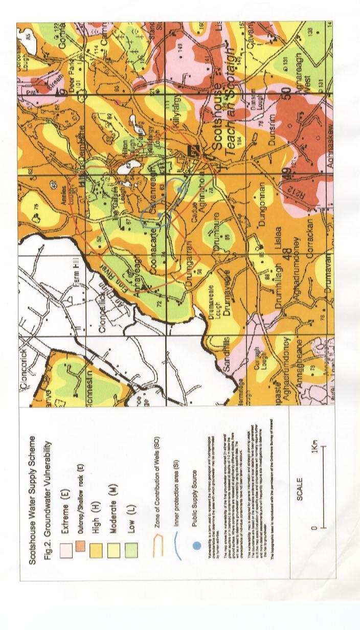
15 The Western and Northern Boundaries are somewhat arbitrary; while they are refined by the numerical modeling, they are based largely on the calculated area required to supply the proposed abstraction rate. In addition, we assume that water will be drawn from whatever distance is necessary to supply the pumping wells. 8.2 Inner Protection Area The Inner Protection Area (SI) is the area defined by a 100-day time of travel (ToT) to the source. It is delineated to protect against the effects of potentially contaminating activities that may have an immediate influence on water quality at the source, in particular microbial contamination. Estimations of the extent of this area cannot be made by hydrogeological mapping and conceptualisation methods alone. By using the aquifer parameters for permeability and hydraulic gradient, 100-day ToT estimations are made. In this case, the 100-day ToT was derived from the MODFLOW model. Numerical modeling gives an average permeability of 4 m d -1, which we have used to calculate the Inner Protection Area (SI) boundary, as shown on Map 3. 9 Vulnerability The distribution of interpreted groundwater vulnerability in the ZOC is presented on Map 2. The subsoils in the ZOC range from low to moderate permeability, and are generally 3 m to 10 m thick, as described in Section Vulnerability categories in the ZOC are predominantly High and Low. The Low Vulnerability materials tend to occur on the drumlin hills, with small areas of Moderate Vulnerability around the base of the hills. The predominantly flat area where the production wells are located, and in the area of Scotshouse itself, are High Vulnerability. There are no areas delineated as Extreme Vulnerability within the ZOC. 9.1 Groundwater Protection Zones The groundwater protection zones are obtained by integrating the two elements of land surface zoning (source protection areas and vulnerability categories) there are eight possible source protection zones. In practice, the source protection zones are obtained by superimposing the vulnerability map on the source protection area map. Each zone is represented by a code e.g. SI/H, which represents an Inner Protection area where the groundwater is highly vulnerable to contamination. These are presented Map 3. There are six groundwater protection zones present around the Scotshouse boreholes as shown below in Table 4. The final groundwater protection map is presented as Map 3. Table 4: Matrix of Source Protection Zones at Scotshouse VULNERABILITY SOURCE PROTECTION RATING Inner (SI) Outer (SO) Extreme (E) Absent Absent High (H) SI/H SO/H Moderate (M) SI/M SO/M Low (L) SI/L SO/L 9.2 Potential Pollution Sources The land in the vicinity of the source is largely grassland-dominated and is primarily used for grazing. Agricultural activities and the few houses in the ZOC are the principal hazards to the boreholes. The main potential sources of pollution within the ZOC are landspreading of organic fertilisers, farmyards, septic tank systems and runoff from roads. The main potential pollutants are faecal bacteria, viruses, cryptosporidium, and nitrogen. 12
16 10 Conclusions and Recommendations The boreholes at Scotshouse are high yielding wells, which are located in a fissured limestone aquifer. However, the geometry of these limestones is such that they are surrounded by low permeability rock. Also, for much of the area the bedrock aquifer is overlain by low permeability sediments which reduce recharge. Both of these factors may restrict the amount of water available to the wells. Vulnerability in the ZOC is predominantly High and Low, with small areas of Moderate. There are no areas of Extreme Vulnerability delineated within the ZOC. The runoff from the roads, houses, farmyards and landspreading pose a threat to the water quality in the two boreholes. The protection zones delineated in the report are based on our current understanding of groundwater conditions and on the available data. Due to the hydrogeological complexity of the area, there is uncertainty regarding some of the boundaries. Overall, our recommendations are as follows: 1. Regular monitoring of water levels in the pumping and observation wells. 2. Chemical and bacteriological analyses of raw water rather than treated water should be carried out on a regular basis at both boreholes. 3. Particular care should be taken when assessing the location of any activities or developments that might cause contamination at the borehole. 4. The potential hazards in the ZOC should be located and assessed. 11 References An Foras Forbartha and Geological Survey of Ireland, Groundwater Resources in The N.E. (R.D.O.) Region; Main Report, Volume pgs. Geraghty, M., Farrelly, I., Claringbold, K., Jordan, C., Meehan, R., and Hudson, M., Geology of Monaghan-Carlingford. A geological description to accompany the Bedrock Geology 1:100,000 Scale Map Series, Sheet 8/9, Monaghan-Carlingford. Geraghty, M. (ed.). Geological Survey of Ireland. 60 pgs. Kevin Cullen & Company, Report on the Drilling and Testing of a Trial and Two Production Wells at Scotshouse, Co. Monaghan. Unpublished report prepared for Monaghan County Council. Kevin Cullen & Company, Report on the Drilling and Testing of Trial Wells No s 2 and 3 at Scotshouse, Co. Monaghan. Unpublished report prepared for Monaghan County Council. Kevin Cullen & Company, Report on the Drilling and Testing of Trial Wells No.1 at Scotshouse, Co. Monaghan. Unpublished report prepared for Monaghan County Council. Swartz, M. and Daly, D Preliminary Assessment of the Hydrogeology near Clones, County Monaghan. Unpublished report prepared for Monaghan County Council. 13
17
18

19
Cappog Bridge (PW-3)
") Water Framework Directive Groundwater Monitoring Programme Site Information Cappog Bridge (PW-3) ImagePath1: Cappog Bridge\IEGBNI_NB_G_012_18_0 01_A_SiteLocation.jpg Cappog Bridge PW-3 is one of 8 boreholes
Water Framework Directive Groundwater Monitoring Programme Site Information Cappog Bridge (PW-3) ImagePath1: Cappog Bridge\IEGBNI_NB_G_012_18_0 01_A_SiteLocation.jpg Cappog Bridge PW-3 is one of 8 boreholes
Water Framework Directive. Groundwater Monitoring Programme. Site Information. Galbally
 Water Framework Directive Groundwater Monitoring Programme Site Information Galbally ImagePath1: Galbally\Galbally1.jpg Galbally source is comprised of 2 boreholes situated in Devonian Old Red Sandstones
Water Framework Directive. Groundwater Monitoring Programme. Site Information. Kiltrough PWS
 Water Framework Directive Groundwater Monitoring Programme Site Information Kiltrough PWS ImagePath1: Kiltrough PWS\17_009_Kiltough_P1_SiteLo cation.jpg This monitoring point is a well that is part of
Dunkerrin - Guilfoyles Well
 Water Framework Directive Groundwater Monitoring Programme Site Information Dunkerrin - Guilfoyles Well ImagePath1: Dunkerrin - Guilfoyles Well\IE_SH_G_19_005_a_Pump House_(800_x_600).jpg Dunkerrin/ Guilfoyles
Water Framework Directive. Groundwater Monitoring Programme. Site Information. Tir na League
 Water Framework Directive Groundwater Monitoring Programme Site Information Tir na League ImagePath1: Tir na League\IE_NW_G_078_05_005_ A_PumpHouse.jpg Tir na League is an infiltration gallery situated
Oola PWS - Carrigmore BH
 Water Framework Directive Groundwater Monitoring Programme Site Information Oola PWS - Carrigmore BH ImagePath1: Oola PWS - Carrigmore BH\OolaPWSCarrigmore1.jpg Oola PWS Carrigmore BH is a borehole used
Water Framework Directive. Groundwater Monitoring Programme. Site Information. Drum Bingahamstown
 Water Framework Directive Groundwater Monitoring Programme Site Information Drum Bingahamstown ImagePath1: Drum Bingahamstown\IE_WE_G_16_ 1_a_Spring.jpg Drum Binghamstown is a spring that is used for a
Proposed Cemetery Thornhill Road. Tier One Hydrogeological Risk Assessment. Peter Mitchell Associates
 Proposed Cemetery Thornhill Road Tier One Hydrogeological Risk Assessment Peter Mitchell Associates January 2015 Executive Summary This report uses a desk-based risk assessment technique published by the
3.0 GEOLOGY AND HYDROGEOLOGY
 3.0 GEOLOGY AND HYDROGEOLOGY 3.1 Methodology The Geological Survey of Ireland (GSI) publication Geology of South Cork was consulted to establish the nature of the bedrock lithology and Quaternary sediments.
1 st Draft Tullamore GWB Description 6 th January 2004
 Hydrometric Area Local Authority 25 Brosna Offaly & Westmeath Co. Co. s Topography Tullamore GWB: Summary of Initial Characterisation. Associated surface water features Associated terrestrial ecosystem(s)
11/22/2010. Groundwater in Unconsolidated Deposits. Alluvial (fluvial) deposits. - consist of gravel, sand, silt and clay
 deposits. - consist of gravel, sand, silt and clay") Groundwater in Unconsolidated Deposits Alluvial (fluvial) deposits - consist of gravel, sand, silt and clay - laid down by physical processes in rivers and flood plains - major sources for water supplies
Groundwater in Unconsolidated Deposits Alluvial (fluvial) deposits - consist of gravel, sand, silt and clay - laid down by physical processes in rivers and flood plains - major sources for water supplies
Castletownroche Water Supply Scheme. Groundwater Source Protection Zones
 Castletownroche Water Supply Scheme Groundwater Source Protection Zones Prepared by: Coran Kelly Geological Survey of Ireland In collaboration with: Cork County Council (Northern Division) 1 INTRODUCTION...
the Quarrying Industry Dewatering and the Quarrying Industry the Quarrying Industry
 Dewatering and the Quarrying Industry Dewatering and Dewatering and the Quarrying Industry the Quarrying Industry Les Brown Eugene P. Daly John Kelly Objectives 1) To present a summary of water management
Connecticut's Aquifers
 Page 1 of 5 DEP Search: Connecticut's Aquifers The technical definition of the word "aquifer" is: any geologic formation capable of yielding significant quantities of water to wells. By that definition,
Hydrogeological Assessment for Part of Lots 2 and 3, Concession 5, Township of Thurlow, County of Hastings 1.0 INTRODUCTION. 1.
 February 10,2017 25506400 Ontario Ltd. Foxboro, ON Attention: Brad Newbatt Re: Hydrogeological Assessment for Part of Lots 2 and 3, Concession 5, Township of Thurlow, County of Hastings 1.0 INTRODUCTION
Land subsidence due to groundwater withdrawal in Hanoi, Vietnam
 Land Subsidence (Proceedings of the Fifth International Symposium on Land Subsidence, The Hague, October 1995). 1AHS Publ. no. 234, 1995. 55 Land subsidence due to groundwater withdrawal in Hanoi, Vietnam
Impact of the Danube River on the groundwater dynamics in the Kozloduy Lowland
 GEOLOGICA BALCANICA, 46 (2), Sofia, Nov. 2017, pp. 33 39. Impact of the Danube River on the groundwater dynamics in the Kozloduy Lowland Peter Gerginov Geological Institute, Bulgarian Academy of Sciences,
Wisconsin s Hydrogeology: an overview
 2012 Soil and Water Conservation Society Conference Stevens Point, WI Feb 9, 2012 Wisconsin s Hydrogeology: an overview Ken Bradbury Wisconsin Geological and Natural History Survey University of Wisconsin-Extension
KANSAS GEOLOGICAL SURVEY Open File Report LAND SUBSIDENCE KIOWA COUNTY, KANSAS. May 2, 2007
 KANSAS GEOLOGICAL SURVEY Open File Report 2007-22 LAND SUBSIDENCE KIOWA COUNTY, KANSAS Prepared by Michael T. Dealy L.G., Manager, Wichita Operations SITE LOCATION The site was approximately four miles
Cape Cross Salt Works PO Box 81307, Windhoek, Namibia. FINAL REPORT rev1 NHN170 NOVEMBER 2016
 Cape Cross Salt Works PO Box 81307, Windhoek, Namibia GROUNDWATER EXPLORATION FOR SUPPLY TO THE CAPE CROSS SALT WORKS FINAL REPORT rev1 NHN170 NOVEMBER 2016 Namib Hydrosearch, PO Box 11546 Windhoek Namibia,
The Geology and Hydrogeology of the Spyhill Area
 The Geology and Hydrogeology of the Spyhill Area Clare North (WorleyParsons Komex) and Martin Ortiz (The City of Calgary) 2-Jul-08 Outline Background Site Location Existing Information New Work Geology
Groundwater Hydrology
 EXERCISE 12 Groundwater Hydrology INTRODUCTION Groundwater is an important component of the hydrologic cycle. It feeds lakes, rivers, wetlands, and reservoirs; it supplies water for domestic, municipal,
Soils, Hydrogeology, and Aquifer Properties. Philip B. Bedient 2006 Rice University
 Soils, Hydrogeology, and Aquifer Properties Philip B. Bedient 2006 Rice University Charbeneau, 2000. Basin Hydrologic Cycle Global Water Supply Distribution 3% of earth s water is fresh - 97% oceans 1%
MAFF Ministry of IfiriLE Agriculture Fisheries and Food
 MAFF Ministry of IfiriLE Agriculture Fisheries and Food STATEMENT OF PHYSICAL CHARACTERISTICS AND AGRICULTURAL LAND CLASSIFICATION UPSLAND, KIRKLINGTON NORTH YORKSHIRE EXTRACTION OF SAND AND GRAVEL MARCH
,Baynes Lake. TO...?&.?...A 2...KO.?'!!&... Sr. *logical Engineer
 > i evernment OF BRITISH COLUMBIA a TO...?&.?...A 2....KO.?'!!&... Sr. *logical Engineer... Grou,,water. Section Hydrology Division Wat.er... In~.~s.tiga.ti.On.s..Branck.... 5 u BJECT...C;.roun.dw.ater...Snve
Newcastle West GWB: Summary of Initial Characterisation.
 Newcastle West GWB: Summary of Initial Characterisation. Hydrometric Area Local Authorities 24 - Deel/ Shannon Estuary Limerick Co. Co. Topography Associated surface water features Rivers: Deel, Daar,
Chapter 2. Regional Landscapes and the Hydrologic Cycle
 Chapter 2. Regional Landscapes and the Hydrologic Cycle W. Lee Daniels Department of Crop and Soil Environmental Sciences, Virginia Tech Table of Contents Introduction... 23 Soils and landscapes of the
Hydrogeology of Karst NE Wisconsin. Dr. Maureen A. Muldoon UW-Oshkosh Geology Department
 Hydrogeology of Karst NE Wisconsin Dr. Maureen A. Muldoon UW-Oshkosh Geology Department WI Bedrock Outline Karst Landscapes Existing WQ Data Flow in Karst Aquifers Overview of Silurian Aquifer Water Level
Bog of the Ring. Groundwater Source Protection Zones. Prepared by: Natalya Hunter Williams Geological Survey of Ireland.
 Bog of the Ring Groundwater Source Protection Zones Prepared by: Natalya Hunter Williams Geological Survey of Ireland Assisted by: Coran Kelly, Geological Survey of Ireland Donal Daly, Geological Survey
Prof. Stephen A. Nelson EENS 111. Groundwater
 Page 1 of 8 Prof. Stephen A. Nelson EENS 111 Tulane University Physical Geology This page last updated on 20-Oct-2003 is water that exists in the pore spaces and fractures in rock and sediment beneath
Identifying Sensitive Aquifers in Ohio
 State of Ohio Environmental Protection Agency Division of Drinking and Ground Waters Identifying Sensitive Aquifers in Ohio May 2007 Ted Strickland, Governor Chris Korleski, Director Acknowledgments Ohio
Geophysical Surveys for Groundwater Modelling of Coastal Golf Courses
 1 Geophysical Surveys for Groundwater Modelling of Coastal Golf Courses C. RICHARD BATES and RUTH ROBINSON Sedimentary Systems Research Group, University of St. Andrews, St. Andrews, Scotland Abstract
=%REPORT RECONNAISSANCE OF CHISHOLM LAKE PROSPECT. October 25, 1977
 =%REPORT ON FIELD RECONNAISSANCE OF CHISHOLM LAKE PROSPECT October 25, 1977 Bruce D. Vincent Imperial Oil Limited, Minerals - Coal, CALGARY, ALBERTA CHISHOLM LAKE PROSPECT Introduction The Chisholm Lake
Michigan s Geology and Groundwater
 Michigan s Geology and Groundwater Ralph J. Haefner Deputy Director U.S. Geological Survey Michigan-Ohio Water Science Center Lansing, Michigan Outline About the USGS Geology 101 Michigan s geology Bedrock
County Limerick Groundwater Protection Scheme. Main Report
 County Limerick Groundwater Protection Scheme Main Report D. O Sullivan, BE, CEng, FIEI, FCIWEM, FIHT County Engineer Limerick County Council Jenny Deakin, Donal Daly and Catherine Coxon Geological Survey
DATA ACQUISITION METHODS FOR GROUNDWATER INVESTIGATION AND THE SITING OF WATER SUPPLY WELLS
 DATA ACQUISITION METHODS FOR GROUNDWATER INVESTIGATION AND THE SITING OF WATER SUPPLY WELLS M.B.J. Foster Tetra Tech EM Inc., San Francisco, CA, USA Keywords: Groundwater, water wells, drilled wells, geophysical
Jim Turenne. Soils on Social Media
 Jim Turenne USDA-NRCS 60 Quaker Lane, Suite 46 Warwick, RI. 02886 401-822-8832 Jim.turenne@ri.usda.gov Soils on Social Media www.twitter.com/soilsne www.fb.com/soilsne www.nesoil.com U.S. Department of
Big Rivers Electric Corporation Disposal of Coal Combustion Residuals (CCR) from Electric Utilities Final Rule CCR Impoundment Liner Assessment Report
 from Electric Utilities Final Rule CCR Impoundment Liner Assessment Report") Big Rivers Electric Corporation Disposal of Coal Combustion Residuals (CCR) from Electric Utilities Final Rule CCR Impoundment Liner Assessment Report CCR Surface Impoundment Information Name: Operator:
Big Rivers Electric Corporation Disposal of Coal Combustion Residuals (CCR) from Electric Utilities Final Rule CCR Impoundment Liner Assessment Report CCR Surface Impoundment Information Name: Operator:
Cuyama Basin North Fork Vineyard
 Cuyama Basin North Fork Vineyard Company Background plus Data Insights to Support GSP Development for the Cuyama Basin Presented by Grapevine Capital Partners and Cleath-Harris Geologists April 26th, 2018
How to Identify and Properly Classify Drill Cuttings
 How to Identify and Properly Classify Drill Cuttings (Creating Useful Borehole Logs) Dave Larson Hydrogeology and Geophysics Section Accurate information about the borehole location and a careful description
Procedure for Determining Near-Surface Pollution Sensitivity
 Procedure for Determining Near-Surface Pollution Sensitivity Minnesota Department of Natural Resources Division of Ecological and Water Resources County Geologic Atlas Program March 2014 Version 2.1 I.
FORENSIC GEOLOGY A CIVIL ACTION
 NAME 89.215 - FORENSIC GEOLOGY A CIVIL ACTION I. Introduction In 1982 a lawsuit was filed on behalf of eight Woburn families by Jan Schlictmann. The suit alleged that serious health effects (childhood
Maggie Payne Jim Turenne
 Maggie Payne Jim Turenne USDA-NRCS 60 Quaker Lane, Suite 46 Warwick, RI. 02886 401-822-8832 maggie.payne@ri.usda.gov U.S. Department of Agriculture 1935: Soil Conservation Service (SCS) Natural Resources
How Can We Sustain Groundwater Quality in Karst and Fracturedcarbonate. Maureen A. Muldoon Geology Department Univ. Of Wisconsin-Oshkosh
 How Can We Sustain Groundwater Quality in Karst and Fracturedcarbonate Aquifers? Maureen A. Muldoon Geology Department Univ. Of Wisconsin-Oshkosh The Question Karst and fracturedcarbonates form productive,
 12 10 8 6 4 2 0 40-50 50-60 60-70 70-80 80-90 90-100 Fresh Water What we will cover The Hydrologic Cycle River systems Floods Groundwater Caves and Karst Topography Hot springs Distribution of water in
The Soils and Land Capability for Agriculture. Land North of Aberdeen, Aberdeenshire
 The Soils and Land Capability for Agriculture Of Land North of Aberdeen, Aberdeenshire Report prepared for Peter Radmall Associates May 2012 Reading Agricultural Consultants Ltd Beechwood Court, Long Toll,
RESISTIVITY IMAGING AND BOREHOLE INVESTIGATION OF THE BANTING AREA AQUIFER, SELANGOR, MALAYSIA. A.N. Ibrahim Z.Z.T. Harith M.N.M.
 JOURNAL OF ENVIRONMENTAL HYDROLOGY The Electronic Journal of the International Association for Environmental Hydrology On the World Wide Web at http://www.hydroweb.com VOLUME 11 2003 RESISTIVITY IMAGING
Evaluation of Subsurface Formation of Pabna District, Bangladesh
 IOSR Journal of Applied Geology and Geophysics (IOSR-JAGG) e-issn: 2321 0990, p-issn: 2321 0982.Volume 1, Issue 4 (Sep. Oct. 2013), PP 30-36 Evaluation of Subsurface Formation of Pabna District, Bangladesh
Evaluation/Monitoring Report No. 152
 Evaluation/Monitoring Report No. 152 150m west of 7 Portmore Rd. Portmore Lower Ballinderry County Antrim LICENCE NO.: AE/07/241 David McIlreavy 1 Site Specific Information Site Name Townland County :
Chapter 8 Fetter, Applied Hydrology 4 th Edition, Geology of Groundwater Occurrence
 Chapter 8 Fetter, Applied Hydrology 4 th Edition, 2001 Geology of Groundwater Occurrence Figure 8.42. Alluvial Valleys ground-water region. Fetter, Applied Hydrology 4 th Edition, 2001 Fetter, Applied
Figure 1 The map shows the top view of a meandering stream as it enters a lake. At which points along the stream are erosion and deposition dominant?
 1. In which type of climate does chemical weathering usually occur most rapidly? 1. hot and dry 3. cold and dry 2. hot and wet 4. cold and wet 2. Figure 1 The map shows the top view of a meandering stream
Geology and New England Landscapes
 Geology and New England Landscapes Jim Turenne, CPSS USDA-NRCS Warwick, RI. http://nesoil.com Why Geology? Provides the big picture of site conditions. Major part of soil formation (parent material and
Sediment and sedimentary rocks Sediment
 Sediment and sedimentary rocks Sediment From sediments to sedimentary rocks (transportation, deposition, preservation and lithification) Types of sedimentary rocks (clastic, chemical and organic) Sedimentary
Name: Mid-Year Review #2 SAR
 Name: Mid-Year Review #2 SAR Base your answers to questions 1 through 3 on on the diagram below, which shows laboratory materials used for an investigation of the effects of sediment size on permeability,
HISTORY OF CONSTRUCTION FOR EXISTING CCR SURFACE IMPOUNDMENT PLANT GASTON ASH POND 40 CFR (c)(1)(i) (xii)
(1)(i) (xii)") HISTORY OF CONSTRUCTION FOR EXISTING CCR SURFACE IMPOUNDMENT PLANT GASTON ASH POND 40 CFR 257.73(c)(1)(i) (xii) (i) Site Name and Ownership Information: Site Name: E.C. Gaston Steam Plant Site Location:
HISTORY OF CONSTRUCTION FOR EXISTING CCR SURFACE IMPOUNDMENT PLANT GASTON ASH POND 40 CFR 257.73(c)(1)(i) (xii) (i) Site Name and Ownership Information: Site Name: E.C. Gaston Steam Plant Site Location:
Groundwater Investigation SOUTHGATE GRAVEL PIT Part of Lot 15, Concession 15 (formerly Township of Proton), Township of Southgate.
, Township of Southgate.") Groundwater Investigation SOUTHGATE GRAVEL PIT Part of Lot 15, Concession 15 (formerly Township of Proton), Township of Southgate County of Grey October, 2014 Prepared for: Drysdale Aggregate Consulting
Groundwater Investigation SOUTHGATE GRAVEL PIT Part of Lot 15, Concession 15 (formerly Township of Proton), Township of Southgate County of Grey October, 2014 Prepared for: Drysdale Aggregate Consulting
' International Institute for Land Reclamation and Improvement. 2 Groundwater Investigations. N.A. de Ridder'? 2.1 Introduction. 2.
 2 Groundwater Investigations N.A. de Ridder'? 2.1 Introduction Successful drainage depends largely on a proper diagnosis of the causes of the excess water. For this diagnosis, one must consider: climate,
Betsy Stevenson and Allison Mohrs (Skagit County Planning and Development Services) Jenny Baker, The Nature Conservancy
 Jenny Baker, The Nature Conservancy") TC Fisher Slough Final Design and Permitting Subject: Well Review Memorandum To: From: Betsy Stevenson and Allison Mohrs (Skagit County Planning and Development Services) Jenny Baker, The ature Conservancy
TC Fisher Slough Final Design and Permitting Subject: Well Review Memorandum To: From: Betsy Stevenson and Allison Mohrs (Skagit County Planning and Development Services) Jenny Baker, The ature Conservancy
Groundwater Resources of Missouri. Cynthia Brookshire, R. G.
 Groundwater Resources of Missouri Cynthia Brookshire, R. G. GROUNDWATER... Water beneath the Earth s surface within a zone of saturation AQUIFER... A geologic formation or group of formations that are
Evolution of the conceptual hydrogeologic and ground-water flow model for Las Vegas Valley, Clark County, Nevada
 Evolution of the conceptual hydrogeologic and ground-water flow model for Las Vegas Valley, Clark County, Nevada Geological Society of America Annual Meeting November 14, 2 David J. Donovan Southern Nevada
Buried-valley Aquifers: Delineation and Characterization from Reflection Seismic and Core Data at Caledon East, Ontario
 Buried-valley Aquifers: Delineation and Characterization from Reflection Seismic and Core Data at Caledon East, Ontario Russell, H.A.J. 1, S.E. Pullan 1, J.A. Hunter 1, D.R. Sharpe 1, and S. Holysh 2 1
Environmental Scoping Report for the proposed establishment of a New Coal-Fired Power Station in the Lephalale Area, Limpopo Province
 8. GEOLOGY, SOILS AND AGRICULTURAL POTENTIAL 8.1. Geology 8.1.1. Candidate Site Geology Due to the layered natured of the geology and various structures the candidate sites are underlain by differing geological
ENGINEER S CERTIFICATION OF FAULT AREA DEMONSTRATION (40 CFR )
") PLATTE RIVER POWER AUTHORITY RAWHIDE ENERGY STATION BOTTOM ASH TRANSFER (BAT) IMPOUNDMENTS LARIMER COUNTY, CO ENGINEER S CERTIFICATION OF FAULT AREA DEMONSTRATION (40 CFR 257.62) FOR COAL COMBUSTION RESIDUALS
PLATTE RIVER POWER AUTHORITY RAWHIDE ENERGY STATION BOTTOM ASH TRANSFER (BAT) IMPOUNDMENTS LARIMER COUNTY, CO ENGINEER S CERTIFICATION OF FAULT AREA DEMONSTRATION (40 CFR 257.62) FOR COAL COMBUSTION RESIDUALS
Which map shows the stream drainage pattern that most likely formed on the surface of this volcano? A) B)
 B)") 1. When snow cover on the land melts, the water will most likely become surface runoff if the land surface is A) frozen B) porous C) grass covered D) unconsolidated gravel Base your answers to questions
1. When snow cover on the land melts, the water will most likely become surface runoff if the land surface is A) frozen B) porous C) grass covered D) unconsolidated gravel Base your answers to questions
Chapter 13. Groundwater
 Chapter 13 Groundwater Introduction Groundwater is all subsurface water that completely fills the pores and other open spaces in rocks, sediments, and soil. Groundwater is responsible for forming beautiful
GOVERNMENT OF NEPAL MINISTRY OF IRRIGATION GROUND WATER RESOURCES DEVELOPMENT BOARD BABARMAHAL, KATHMANDU, NEPAL
 GOVERNMENT OF NEPAL MINISTRY OF IRRIGATION GROUND WATER RESOURCES DEVELOPMENT BOARD BABARMAHAL, KATHMANDU, NEPAL GIS Based Updating of Groundwater Level Siraha District Final Report Submitted to Ground
Groundwater Rebound in the South Yorkshire Coalfield: A review of initial modelling
 Groundwater Rebound in the South Yorkshire Coalfield: A review of initial modelling 1 S. P. Burke, 1 H. A.B. Potter and 2 A. Jarvis 1 Environment Agency: Science Group, Olton Court, Olton,Solihull UK 2
Section I: Multiple Choice Select the best answer to each question. Mark your final answer on the answer sheet. (1 pt each)
") Sedimentary Rocks & Surface Processes Quest Name: Earth Science 2013 Block: Date: Section I: Multiple Choice Select the best answer to each question. Mark your final answer on the answer sheet. (1 pt each)
Sedimentary Rocks & Surface Processes Quest Name: Earth Science 2013 Block: Date: Section I: Multiple Choice Select the best answer to each question. Mark your final answer on the answer sheet. (1 pt each)
Introduction to Soil Science and Wetlands Kids at Wilderness Camp
 Introduction to Soil Science and Wetlands Kids at Wilderness Camp Presented by: Mr. Brian Oram, PG, PASEO B.F. Environmental Consultants http://www.bfenvironmental.com and Keystone Clean Water Team http://www.pacleanwater.org
DETECTION OF GROUNDWATER POLLUTION USING RESISTIVITY IMAGING AT SERI PETALING LANDFILL, MALAYSIA
 JOURNAL OF ENVIRONMENTAL HYDROLOGY The Electronic Journal of the International Association for Environmental Hydrology On the World Wide Web at http://www.hydroweb.com VOLUME 8 2000 DETECTION OF GROUNDWATER
GEOL.3250 Geology for Engineers Glacial Geology
 GEOL.3250 Geology for Engineers Glacial Geology NAME Part I: Continental Glaciation Continental glaciers are large ice sheets that cover substantial portions of the land area. In the region of accumulation
Geology and hydrology of Tuaran
 Allnllal Geological Conference '96 ~~~~~ Jllne 8-9,1996, [(ota [(illaballl, Sabah Geology and hydrology of Tuaran MAJEED M. FAISAL, SHARIFF A.K. OMANG AND SANUDIN HJ. TAHIR University Malaysia Sabah Km
Differentiation of chloride source using stable chlorine isotopes
 Differentiation of chloride source using stable chlorine isotopes RemTech 2009 Banff, Alberta October 14-16 2009 Dr. Alec Blyth and Tom Anthony 1 1 currently City of Calgary Background: DOW Chemical Canada
Hydro One (Sept 2014) Hydro One (Sept 2014) Hydro One (Sept 2014)
 Hydro One (Sept 2014) Hydro One (Sept 2014)") TABLE 1 WELL CONSTRUCTION DETAILS MOE WWR No Well ID Location Installation Date Status Easting Coordinates Northing Source Elevation Screened Interval Screened Material Borehole Well Stick-up Ground Top
TABLE 1 WELL CONSTRUCTION DETAILS MOE WWR No Well ID Location Installation Date Status Easting Coordinates Northing Source Elevation Screened Interval Screened Material Borehole Well Stick-up Ground Top
June 9, R. D. Cook, P.Eng. Soils Engineer Special Services Western Region PUBLIC WORKS CANADA WESTERN REGION REPORT ON
 PUBLIC WORKS CANADA WESTERN REGION REPORT ON GEOTECHNICAL INVESTIGATION PROPOSED MARTIN RIVER BRIDGE MILE 306.7 MACKENZIE HIGHWAY Submitted by : R. D. Cook, P.Eng. Soils Engineer Special Services Western
4. The map below shows a meandering stream. Points A, B, C, and D represent locations along the stream bottom.
 1. Sediment is deposited as a river enters a lake because the A) velocity of the river decreases B) force of gravity decreases C) volume of water increases D) slope of the river increases 2. Which diagram
 UNIT DESCRIPTIONS: Artificial Fill, Undocumented (Afu): Locally derived sandy silt and silty sand, locally with clay and varying amounts of gravel and man-made debris. Abundant concrete rubble, in places
Case Study: University of Connecticut (UConn) Landfill
 Landfill") Case Study: University of Connecticut (UConn) Landfill Problem Statement:» Locate disposal trenches» Identify geologic features and distinguish them from leachate and locate preferential pathways in fractured
Case Study: University of Connecticut (UConn) Landfill Problem Statement:» Locate disposal trenches» Identify geologic features and distinguish them from leachate and locate preferential pathways in fractured
Geology and Soils. Technical Memorandum
 Geology and Soils Technical Memorandum TO: FDOT FROM: HDR, Inc. DATE: February 2013 PROJECT: St Johns River Crossing FPID No: 208225-3-21-01 Clay, Duval, and St. Johns Counties; Florida Geology and soils
TAMPA BAY TRIBUTARIES BASIN. Hydrogeological Setting
 TAMPA BAY TRIBUTARIES BASIN Hydrogeological Setting Aquifers within the Tampa Bay Tributaries Basins ground water flow system include the Floridan aquifer system, the intermediate aquifer system, and the
STATEMENT OF PHYSICAL CHARACTERISTICS REPORT FOR WELLINGTON, HEREFORD AND WORCESTER MINERALS LOCAL PLAN
 STATEMENT OF PHYSICAL CHARACTERISTICS REPORT FOR WELLINGTON, HEREFORD AND WORCESTER MINERALS LOCAL PLAN M J Wood ADAS Ref: 25/RPT/0039 Resource Planning Team Job No: 164/94 ADAS Statutory Group MAFF Ref:
Name. 4. The diagram below shows a soil profile formed in an area of granite bedrock. Four different soil horizons, A, B, C, and D, are shown.
 Name 1. In the cross section of the hill shown below, which rock units are probably most resistant to weathering? 4. The diagram below shows a soil profile formed in an area of granite bedrock. Four different
Groundwater Sensitivity Regions of Kentucky
 Groundwater Sensitivity Regions of Kentucky by Kentucky Department for Environmental Protection Division of Water Groundwater Branch 1994 Interpreted by Joseph A. Ray James S. Webb Phillip W. O'dell Scale
STUDY GUIDE FOR CONTENT MASTERY. Movement and Storage of Groundwater
 Groundwater SECTION 10.1 Movement and Storage of Groundwater In your textbook, read about the hydrosphere, precipitation and groundwater, and groundwater storage. Use the following terms to complete the
Essentials of Geology, 11e
 Essentials of Geology, 11e Groundwater Chapter 10 Instructor Jennifer Barson Spokane Falls Community College Geology 101 Stanley Hatfield Southwestern Illinois Co Jennifer Cole Northeastern University
Freshwater. 1. The diagram below is a cross-sectional view of rain falling on a farm field and then moving to the water table.
 Name: ate: 1. The diagram below is a cross-sectional view of rain falling on a farm field and then moving to the water table. 3. Which conditions produce the most surface water runoff? A. steep slope,
 5.2 APPENDIX D2 Geotechnical Report Jeffares & Green: 03524: Ilinge and Lesseyton Cemetery Development ILINGE AND LESSEYTON CEMETERY DEVELOPMENT - GEOTECHNICAL INVESTIGATION FINAL REPORT SEPTEMBER 2014
UK Flooding Feb 2003
 UK Flooding 2000 06 Feb 2003 Britain has taken a battering from floods in the last 5 years, with major events in 1998 and 2000, significant floods in 2001 and minor events in each of the other years. So
Finding Large Capacity Groundwater Supplies for Irrigation
 Finding Large Capacity Groundwater Supplies for Irrigation December 14, 2012 Presented by: Michael L. Chapman, Jr., PG Irrigation Well Site Evaluation Background Investigation Identify Hydrogeologic Conditions
Sedimentary Rocks. Weathering. Mechanical & Chemical Weathering. Sediments. Lithification. Deposition. Transport. Erosion.
 Lithification Sedimentary Rocks Sediments Deposition Transport Erosion Weathering Weathering The sediments that make up sedimentary rocks are produced by: Mechanical & Chemical Weathering Mechanical Weathering
Physiographic zones. and water quality
 Southland Physiographic zones bedrock/hill country Technical information Physiographic zones are part of the Water and Land 2020 & Beyond project that aims to maintain and improve water quality in the
1 Water Beneath the Surface
 CHAPTER 16 1 Water Beneath the Surface SECTION Groundwater KEY IDEAS As you read this section, keep these questions in mind: What are two properties of aquifers? How is the water table related to the land
Colluvial debris: Rocks that have fallen down hills. Types of Parent Material
 Weathered Rocks from the lithosphere are the parent materials for soils Nature of the parent material will greatly influence time it takes to make soil and the nature of the soil that is formed Types of
AGENDA ITEM 6 APPENDIX /0151/DET GROUND WATER & SURFACE WATER MANAGEMENT PLAN
 CAIRNGORMS NATIONAL PARK AUTHORITY Planning Committee Agenda Item 6 Appendix 18 12/10/2018 AGENDA ITEM 6 APPENDIX 18 2018/0151/DET GROUND WATER & SURFACE WATER MANAGEMENT PLAN Dalwhinnie Quarry Ground
IPMO2-1. Groundwater Modelling of Chiang Rai Basin, Northern Thailand. Sattaya Intanum* Dr.Schradh Saenton**
 IPMO2-1 Groundwater Modelling of Chiang Rai Basin, Northern Thailand Sattaya Intanum* Dr.Schradh Saenton** ABSTRACT Chiang Rai basin, situated in Chiang Rai and Phayao provinces covering an area of 11,000
Groundwater in Bayfield County
 Groundwater in Bayfield County Presented to Bayfield County Large Scale Livestoc Study Committee April 23, 2015 Madeline Gotowitz Hydrogeologist Groundwater in Bayfield County Groundwater basics Hydrogeology
EPS 50 Lab 4: Sedimentary Rocks
 Name: EPS 50 Lab 4: Sedimentary Rocks Grotzinger and Jordan, Chapter 5 Introduction In this lab we will classify sedimentary rocks and investigate the relationship between environmental conditions and
Delineation of Zones at Risk from Groundwater Inflows at an Underground Platinum Mine in South Africa
 Delineation of Zones at Risk from Groundwater Inflows at an Underground Platinum Mine in South Africa Mr Andreas Stoll andreas.stoll@erm.com Environmental Resources Management Swiss GmbH (ERM), Switzerland
MEMORANDUM. wa.tsr..-z.n~.e.s-t.i~at.i.o.ns... Branch... Mr. Webster contends that prior to excavation of the gravel
 TO... J. C. Foweraker 2... Head Gr o w a t er S e c t i on... Hyar....og~~~.~.~vis.ion... wa.tsr..-z.n~.e.s-t.i~at.i.o.ns... Branch... eernment OF BRITISH COLUMBIA MEMORANDUM II 0 PROM A. P. Kohut, Geological