Nine Minimum Controls No. 2
|
|
|
- Janice Anderson
- 5 years ago
- Views:
Transcription
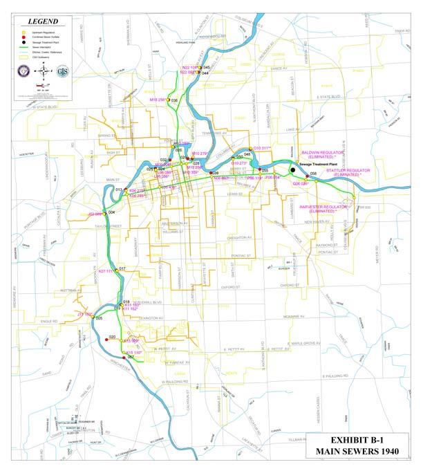
1 Nine Minimum Controls No MAXIMIZATION OF STORAGE IN THE COLLECTION SYSTEM 2.1 OVERVIEW The 2 nd NMC is titled Maximization of Storage in the Collection system. EPA s NMC Guidance explains that this NMC means making relatively simple modifications to the CSS to enable the system itself to store wet weather flows.. CSOs can be reduced by eliminating bottlenecks and obstructions in the collection system that cause upstream overflows before the WPCP is at capacity. CSOs can also be reduced by maximizing storage in the collection system. The City s WPCP was designed to treat sewage at a peak maximum rate of approximately 60 million gallons per day (MGD). Were it possible (it is not) for the WPCP to treat at a constant rate of 60 MGD for 24 hours a day, 365 days a year, the WPCP could theoretically treat approximately 21,900 million gallons (MG) of flow per year. The City s collection system has delivered as average of approximately 43 MGD of sewage to the WPCP. Given the WPCP s design peak capacity of 60 MGD, the WPCP would, theoretically, treat up to an average of 17 MGD (60 MGD 43 MGD) of wet weather runoff each day, or 6,205 MG of wet weather runoff each year. Unfortunately, neither sewage nor wet weather runoff are produced at a constant rate. The City s challenge during wet weather events is to utilize as much of the WPCP capacity as possible. One important means to help the City meet this challenge is the storage of flows when flow to the WPCP is greater than its capacity and by releasing stored flow to the WPCP when flow to the WPCP is less than its capacity. This Chapter will describe how the major components of the collection system operate, provide information on bottlenecks and obstructions, and analyze the feasibility of utilizing storage in the collection system to store peak wet weather flows. Other measures associated with NMC No. 2, including collection system inspection, tide gate maintenance and repair and removal of obstructions to flow are addressed in Chapter OPERATION OF THE COLLECTION SYSTEM Originally trunk sewers, highlighted in orange in Exhibit B-1, were built to transport the combined sewage from combined sewer subbasins directly to receiving waters. The boundaries of the combined sewer subbasins are outlined in yellow on Exhibit B-1. City of Fort Wayne Amended CSO Operational Plan
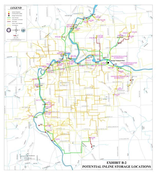
2 Nine Minimum Controls No. 2 When the WPCP was constructed a series of interceptors was built to transport dry weather flow. Exhibit B-1 shows the major interceptor sewers. The interceptors (or section of interceptors) that transport combined sewage to the WPCP are highlighted in green. Regulators were constructed to convey combined sewage from subbasin trunk sewers to the interceptor sewers. The regulators were also constructed to control the volume of combined sewage that flows to the interceptor system. This was done to protect the biological processes at the WPCP. Regulators are shown on the Exhibit B-1 as yellow dots. They are labeled with the City s 6-digit structure identification number. During some wet weather events, interceptor capacity can be exceeded. Flows of combined sewage that does not get into an interceptor are routed to a receiving water through a permitted CSO outfall. The City s CSO outfalls are indicated by a large black dot on Exhibit B-1 and labeled with the City s NPDES Permit number for that location. Exhibit B-1 shows the City s sewer system as it was in Exhibit B-2 shows the same system in Note that the 2005 system remains comprised of combined sewer subbasins, subbasin trunk sewers, regulators, interceptor sewers and the WPCP. 2.3 ELIMINATION OF BOTTLENECKS AND OBSTRUCTIONS Perhaps the City s foremost means to identify and eliminate bottlenecks within its CSS are its inspection and maintenance programs (see Chapter 1). CSO outfalls and regulators are inspected daily and also on weekends in connection with any wet weather events. These inspections, in addition to other scheduled inspections, proactive preventative maintenance, and other activities enable to City to identify system constraints (e.g. flow obstructions) and promptly effect solutions. Ineffective pump stations are a common collection system bottleneck in many systems. All of the City s interceptors that carry combined sewage flow by gravity to the WPCP - there are no pump stations in the interceptor system. All of the combined sewer subbasins are served by gravity trunk sewers. No combined sewage is pumped to the regulators. Combined sewage is pumped from a regulator to an interceptor in only one subbasin (O10-101). The pumps in this subbasin are sized to pump the maximum amount of combined sewage (more than peak dry weather flows) that the downstream interceptor can handle. These pumps have been provided with an alternate power supply (2 nd electrical feed) to mitigate against an overflow being caused by a power failure. In addition, comminutors have been installed to improve reliability and prevent damage to the pumps from debris. City of Fort Wayne Amended CSO Operational Plan
3 Nine Minimum Controls No. 2 Another common collection system bottlenecks are undersized pipes pipes which flow to smaller downstream pipes. Pipe capacities for both the interceptor sewers and trunk sewers were analyzed during the development of the City s electronic sewer model. All trunk sewers increase in size and capacity as they approach regulators or interceptors. All interceptor sewers increase in size and capacity as they approach the WPCP. Finally, regulators are engineered bottlenecks in many collection systems. Regulators are designed to impose a maximum limit on the flow to the WPCP. The maximum limitation is created by the size of the opening to the interceptor and by gates that reduce the opening size. All but five of the City s mechanical regulator gates are chained fully open to allow maximum flow to the interceptor (in allowing the maximum flow, the potential for CSOs is not significantly increased.) Those that are not chained fully open are set to operate at maximum capacity. This maximizes the flow that can get into the interceptors without rebuilding the regulator. The City recognizes that maximizing flow to the interceptor reduces the potential for inline storage in the subbasins but at the same time (as described in Section below) acknowledges that many trunk sewers are too shallow to present additional storage capacity without creating a greater risk of basement backups and flooding. A CSS modeling study was performed as part of Section 2.4 to evaluate the potential of partially closing some of regulator gates. Results are located in Exhibit B UTILIZATION OF COLLECTION SYSTEM STORAGE The first step in maximizing collection system storage capacity is identifying the locations of potential storage. Storage can be found on the ground above the collection system, in collection pipes, and in collection system tanks or ponds. The second step in maximizing collection system storage capacity is identifying and analyzing possible modifications that increase the utilization of in-system storage. The analysis considers the amount of storage available, the risk of upstream (street, basement) flooding, and the increase in O&M requirements should be analyzed Ground Above the Collection System One of the steps in developing projects for the City s Combined Sewer System Capacity Improvement Program (CSSCIP) has been to identify potential solutions to capacity problems through public brainstorming workshops and the City s Sewer Advisory Group. One option evaluated at these workshops for solutions to capacity issues in each basin is utilizing public streets and/or parking areas for temporary wet weather storage. More than half of the entire combined sewer subbasin area has been through this process. To date, no locations have been identified where street storage has presented an acceptable community solution. Each City of Fort Wayne Amended CSO Operational Plan
4 Nine Minimum Controls No. 2 subbasin studied has a final report summarizing the findings of the evaluation Collection Pipes The City s interceptor sewers have the capacity to deliver more than 120 million gallons of flow per day to its WPCP. Average daily flow to the WPCP is in the range of 40 to 48 MGD. This suggests that there is ample available storage in the interceptor sewers. This storage is currently used automatically. The combined sewer subbasin trunk sewers are another potential location for storage of peak flows. The trunk sewers in the 2005 version of the City s sewer system are highlighted on Exhibit B-2 in orange. Trunk sewers, however, are often not as deep as interceptor sewers. In-line storage in truck sewers, consequently, represents a greater potential to cause flooding in basements, yards, and streets. Nonetheless, the City conducted a study done to assess the potential of using trunk sewers for insystem storage. A copy of the study can be found at Exhibit B-3. Several potential locations for in-system storage were identified in the study. In several instances, the study recommended weir adjustments which have since been implemented as noted in Exhibit B-6. Many other recommendations of the study, however, entail significant engineering and high costs well exceeding the scope of an NMC Collection System Tanks and CSO Ponds Pumps are used at 5 of the City s CSO discharge points to pump the overflow into the receiving waters. General information on these pump stations can be found at Exhibit A-2. If the wet wells associated with these pumps are kept dewatered during dry weather, the wet wells could be used to capture and store small overflows. The volume of each of the five pump station wet wells that could potentially be dewatered back to the interceptor is approximately: Griswold Pump Station Nebraska Pump Station Brown Street Pump Station Morton Street CSO Pump Station Third Street Pump Station MG MG, MG MG MG The City is working to rehabilitate and replace dewatering pumps in these wet wells to allow use of the wet wells for storage. The dewatering pumps are also being re-routed to pump to interceptor sewers rather that the receiving water. By the end of 2007, four of these five CSO discharge stations will have dewatering pumping systems installed in their wet wells. City of Fort Wayne Amended CSO Operational Plan
5 Nine Minimum Controls No. 2 Due to the low frequency of discharges at the Griswold station, it will not be effective to install a dewatering pump system in its wet well. Instead, access improvements to the wet well have been performed so that the wet well can be vacuumed out. The installation of these dewatering systems is expected to lower the number of CSO events at these locations, as well as reduce the overflow volume of some of the CSO events. Following completion of this work and observation of the results, the CSS model will be updated to incorporate these dewatering capabilities. The City s collection system contains 2 large ponds that are currently used to detain combined sewage flows from the Glasglow regulator and Wayne Street Interceptor overflow in excess of WPCP capacity. The ponds are currently without operating facilities to return their combined sewage flows to the WPCP. The City studied how much combined sewage could be returned to the WPCP if appropriate facilities existed in the future. A copy of this study can be found at Exhibit B-4. Conceptual designs for return structures were developed by Donohue & Associates Inc. in A section of their report showing the design and calculations of the associated costs are shown at Exhibit B-5. The study makes it clear that significant engineering and costs would be required to construct the requisite return facilities. Return facilities, therefore, will not be implemented as an NMC. Through its LTCP, however, the City will be constructing initial improvements in 2008 which will then allow the limited dewatering of flows captured by the ponds to the WPCP. Improvements allowing a higher volume of dewatering will be scheduled as LTCP improvements in connecting with improvements to the WPCP itself. 2.5 TIDE GATE INSPECTIONS Tide gates that do not seal or operate properly can admit significant volumes of water back into the collection system. The City has a tide gate inspection and maintenance program as described in Exhibit A-1 WPCM O&M Plan. In addition to the maintenance activities at Exhibit A-1, the City works to inspect tide gates in connection with the daily monitoring of the City s CSO monitoring program. 2.6 RETARDING INFLOWS - INFILTRATION & INFLOW REDUCTION Sewer systems can experience significant impacts from inflow and infiltration (I&I) of rain water and ground water. The 1995 Wastewater Master Plan identified areas where high priority and cost effective inflow removal was recommended. The City has hired a sewer program manager with responsibilities that include I&I reduction in the sewer collection system. This program manager helps monitor the City s goal of performing wet weather inspections on 450 City of Fort Wayne Amended CSO Operational Plan
6 Nine Minimum Controls No. 2 manholes each year, as well as coordinating flow monitoring in areas where I&I impacts are suspected. Manhole rehabilitation and sewer pipe CIPP lining projects are developed by the program manager and used to reduce sources of I&I in the public portion of the sewer collection system. The City also has developed a video and pamphlet on downspout disconnection for property owners to reduce private I&I and has conducted a pilot downspout disconnection project. 2.7 RECORDKEEPING A project list of weir adjustment activities to date is shown at Exhibit B-6. At the end of each calendar year this list will be updated with a status report describing the progress of the various projects. The progress reports will be kept in Exhibit B-7. City of Fort Wayne Amended CSO Operational Plan
7 Nine Minimum Controls No. 2 DIRECTORY FOR APPENDIX B (Items Presented in Order of Appearance in Appendix B) Item Description Exhibit B-1 MAIN SEWERS 1940 Exhibit B-2 POTENTIAL INLINE STORAGE LOCATIONS Exhibit B-3 COMBINED SEWER SYSTEM INLINE STORAGE ASSESSMENT STUDY Exhibit B-4 CSO PONDS NOS. 1&2 RECYCLE STUDY Exhibit B-5 WPCP CSO TERMINAL PONDS NOS. 1&2 RECYCLE STUDY Exhibit B-6 PROJECT LIST Exhibit B-7 RECORDKEEPING City of Fort Wayne Amended CSO Operational Plan
8 Nine Minimum Controls No. 2 EXHIBIT B-1 City of Fort Wayne Amended CSO Operational Plan Report
9 151
10 Nine Minimum Controls No. 2 EXHIBIT B-2 City of Fort Wayne Amended CSO Operational Plan Report
11 153
12 Nine Minimum Controls No. 2 EXHIBIT B-3 City of Fort Wayne Amended CSO Operational Plan Report
13 COMBINED SEWER SYSTEM INLINE STORAGE ASSESSMENT STUDY TECHNICAL MEMORANDUM NO. 1.2 CITY OF FORT WAYNE, INDIANA NOVEMBER 2004 (Technical Memorandum No. 1) Revised: MARCH 2005 (Technical Memorandum No. 1.1) Revised: AUGUST 2005 (Technical Memorandum No. 1.2) Revised: SEPTEMBER
14 1.0 STUDY OBJECTIVES The Environmental Protection Agency (EPA) and the Indiana Department of Environmental Management (IDEM) have established Nine Minimum Controls (NMCs) that Combined Sewer Overflow (CSO) communities should employ to optimize operation of the collection system and reduce overflows. The Nine Minimum Controls form the basis for the City of Fort Wayne s Combined Sewer System Operational Plan (CSSOP). Maximum use of collection system storage is one of the NMCs. Under NMC requirements, maximizing use of the collection system for storage can include incorporating relatively simple modifications to the collection system to store wet weather flows to reduce CSO discharges, if those modifications do not create hydraulic or system flooding concerns. The overall goal of this project is to perform an assessment of the inline storage capacity of the trunk sewers that serve the combined sewer subbasins in Fort Wayne. The assessment will identify the subbasins whose combined trunk sewers have the ability to store ample wet weather flows without causing any detrimental surcharges or basement flooding, and the resulting benefit in terms of reduction in overflow volume. The first phase of this effort is to assess the potential for inline storage using simple screening methodologies, and identify critical locations in the subbasins that control the allowable surcharge. The second phase of this study investigates the operation of the inline storage, and the impact of the filling/dewatering process, through annual model simulations. These simulations provide estimates of reductions in annual overflow volumes with assumed inline storage. The third and final phase predicts the reductions in number of annual overflow events and overflow volumes with increase in weir heights at regulators of selected subbasins. This technical memorandum presents the methodology used to perform these three phases, the details of the evaluation using XP SWMM modeling, and results of the evaluation. Page 1 of
15 2.0 METHODOLOGY USED TO ASSESS POTENTIAL FOR INLINE STORAGE The following method was used to evaluate the storage potential for the combined trunk sewers in subbasins: Step 1. Identify subbasins with trunk sewer sizes larger than 36 inches in diameter. The subbasins with smaller trunk sewer sizes (i.e. less than or equal to 36-inch diameter) were eliminated from further evaluation. It was assumed that subbasins that have trunk sewer size less than 36-inch diameter are not likely to have viable inline storage volume to store adequate wet weather flows. Step 2. For the subbasins that have trunk sewer sizes greater than 36-inch diameter, the full volume of trunk sewers greater than 36-inch diameter was calculated. Step 3. Using results from completed annual continuous model simulations (performed as part of the LTCP development by Malcolm Pirnie in 2001 using XP SWMM), the maximum total annual volume that could be stored in the trunk sewers was estimated. Using the model-predicted overflow hydrographs, the volume of each overflow event was calculated and compared to the available in-line storage. If the overflow volume was less than the available storage, then the event was assumed to be captured in its entirety. If the overflow volume was more than the available storage, then the portion in excess of the available storage was assumed to overflow. It was also assumed that the full storage volume was available for each storm event, i.e., dewatering of the storage was not accounted for. This methodology intentionally provides an estimate of the maximum total annual volume that could be stored. A maximum estimate was desired because the estimated stored volumes were subsequently used in Step 4 to eliminate basins that were clearly not candidates for inline storage. Two Page 2 of
16 assumptions cause the estimate to represent the maximum total annual volume that could be stored: First, as noted above, dewatering of storage was not accounted for. Therefore, in a situation with back-to-back overflow events, it was assumed that the full inline storage volume was available for both events. In reality, the full volume may not be available for the second event, if the overflow from the first event is still being dewatered from storage. Second, it was assumed that the full inline storage volume could be used. In reality, the surcharge necessary to fill the full inline storage volume may be unacceptable, i.e., cause basement flooding conditions in the subbasin. Step 4. If the estimated maximum total annual stored volume is less than 20 percent of the total annual overflow volume, then the associated subbasin was eliminated from further evaluation. This 20 percent cut off point was based on engineering judgment; given that the estimate of benefit in the screening step is conservatively maximized (see above), a 20 percent threshold is considered appropriate Step 5. The subbasins identified above (trunk sewers greater than 36 inches in diameter [Step 1] and meeting the 20 percent criteria [Steps 2, 3 & 4]) are considered viable candidates for inline storage. However, fully assessing the estimated benefit (in terms of reduction in annual overflow volume) from inline storage must also account for the maximum allowable hydraulic grade lines in each subbasin, and the impact from the filling/dewatering process on the capture of sequential overflow events. Step 5 used a design storm analysis to provide a first indication of the wet-weather conditions that trigger an unacceptable hydraulic grade line condition in the trunk sewers under existing conditions. Page 3 of
17 Step 6. The previous step studied the effect of a single rain event on the combined sewer system of the above identified subbasins. As part of Step 6, annual model simulations were performed on these subbasins, incorporating dynamic controls to induce inline storage while maintaining HGL set points. Step 7. The changes to the annual overflow volumes and the number of annual overflow events from existing conditions were documented. Step 8. Subbasins with the ability to pass large rainfall events, and hence the potential ability to store relatively significant volumes were selected as part of Step 8. Annual model simulations were again performed, incorporating increased weir heights as a simpler method of inducing inline storage while maintaining HGL set points. Step 9. The changes to the annual overflow volumes and the number of annual overflow events from existing conditions were again documented. 3.0 ASSESSMENT OF INLINE STORAGE POTENTIAL The City of Fort Wayne has a total of 40 combined sewer subbasins. Out of the 40, 38 subbasins were analyzed for inline storage potential in their respective combined trunk sewers. Subbasins M10120 and Q14025A were not included in the inline storage assessment study because the subbasin models were not calibrated and construction of sewer separation projects has been completed. 3.1 SUBBASINS ELIMINATED BASED ON TRUNK SEWER DIAMETER SIZE (STEP 1) Page 4 of
18 From the total of 38 subbasins, 13 subbasins were eliminated based on the criteria set by Step 1 (Section 2). Table 3-1 lists the subbasins that were eliminated and the largest trunk sewer diameter for the corresponding subbasin. TABLE 3-1 SUBBASINS ELIMINATED BASED ON TRUNK SEWER DIAMETER SIZE Subbasin J02089 K15112 K19071 L06079 M14007 M18256 M18261 N22005 O06017 O22061B Q06002 Q06049 S02008 Largest Diameter of Trunk Sewer 30-inch 24-inch 18-inch 18-inch 12-inch 24-inch 21-inch 24-inch 36-inch 24-inch 24-inch 24-inch 24-inch Page 5 of
19 3.2 SUBBASINS ELIMINATED BASED ON ANNUAL STORED OVERFLOW VOLUME (STEPS 2 TO 4) Table 3-2 lists the subbasins that were eliminated based on the criteria set by Steps 2 through 4 (Section 2) and the total assumed annual stored overflow volume for these subbasins as percent of the total annual overflow volume. TABLE 3-2 SUBASINS ELIMINATED FOR LACK OF STORAGE CAPACITY Subbasin Total Assumed Annual Stored Overflow Volume as Percent of the Total Annual Overflow Volume M % O % M % R % N % 3.3 CANDIDATE SUBBASINS FOR INLINE STORAGE ASSESSMENT STUDY Twenty subbasins remained after the two screening steps described above and so were identified as candidate subbasins for a full assessment of inline storage. Table 3-3 lists the candidate subbasins and their corresponding trunk sewer diameter sizes. Page 6 of
20 TABLE 3-3 CANDIDATE SUBBASINS AND ASSOCIATED TRUNK SEWER DIAMETERS Subbasin Trunk Sewer Diameters J03012 K06290A K06290B K07026 K11004 K11010 K15009 L06078 L06086 L06087/L06438 L19252 M06044 M06711 M10250 N06007 O10101 P06014 P06119 R inch to 60-inch 72-inch 60-inch to 72-inch 42-inch 54-inch to 66-inch 72-inch to 126-inch 42-inch to 72-inch 42-inch to 48-inch 48-inch 42-inch to 72-inch 48-inch to 66-inch 42-inch 42-inch to 60-inch 42-inch to 48-inch 60-inch 42-inch to 66-inch 48-inch to 96-inch 48-inch 42-inch to 48-inch Page 7 of
21 3.4 ESTABLISHING HGL SET POINTS FOR CANDIDATE SUBBASINS As noted above, assessing the benefit of inline storage requires definition of the HGL set points necessary to protect the subbasin from unacceptable surcharge. Knowledge of the local system combined with XP SWMM model results were used to identify the HGL set points. The set points are made up of two measures: First, the locations where the set points are applied. These are manholes that are predicted to exhibit the worst surcharging during simulated design storms. Second, the depth set point that must be maintained. This depth set point was defined based on: 1). For sewers where the depth of pipe crown is greater than 8 feet from grade: Maintain 8 feet of freeboard. 2). For sewers where the depth of pipe crown is less than 8 feet from grade: Maintain non-surcharged conditions. For the remainder of this Technical Memorandum, any discussion of HGL set points refers to the HGL set points identified through the above procedure. 3.5 DESIGN STORM ANALYSIS As an initial indicator of the benefit from inline storage, Malcolm Pirnie performed design storm simulations for the candidate subbasins under existing conditions. The synthetic design storms used for this analysis were defined during the City s LTCP development. The design storms return periods, durations, and rainfall depths are as follows: 1) 3-month, 6-hour storm (1.04 inches) 2) 6-month, 6-hour storm (1.31 inches) 3) 9-month, 6-hour storm (1.49 inches) 4) 1-year, 6-hour storm (1.62 inches) Page 8 of
22 5) 2-year, 6-hour storm (1.89 inches) 6) 5-year, 6-hour storm (2.28 inches) 7) 10-year, 6-hour storm (2.64 inches) 8) 25-year, 6-hour storm (3.22 inches) For each subbasin, the smallest design storm that violated the HGL set points described in Section 3.4 was identified. This design storm is referred to as the critical, or threshold, design storm. It is important to recognize that these simulations were performed assuming existing conditions, i.e., no inline storage. Therefore, they identify the largest design storm for which some level of inline storage can be used. They do not identify the largest design storm that can be fully captured using inline storage. 3.6 RESULTS OF DESIGN STORM ANALYSIS As presented in Sections 3.4 and 3.5, the HGL set points and the threshold design storm that violated the set points were determined for each candidate subbasin. The XP SWMM model simulation results for these subbasins are presented in Table 3-4 under two scenarios: 1) For Sewers with Diameter 42-inch Only (Trunk Sewers) This section of the table presents the results based on the critical HGL set point identified in the 42- inch or greater diameter trunk sewers in the subbasin. Under this scenario, the critical HGL set point may still be violated in smaller-diameter tributary systems within the subbasins. 2) For Entire Subbasin (Trunk Sewers and Sewers with Diameter < 42-inch) This section of the table presents the results based on the critical HGL set point identified for any sewer in the subbasin (including the sewers that are less than 42-inch diameter in size). There could be possible local bottleneck points in the Page 9 of
23 smaller diameter sewers which would surcharge or flood for a smaller storm even though the trunk sewers have the capacity to handle a much larger storm. The model results presented in Table 3-4 indicate the following assuming an HGL set point in the 42-inch or greater diameter sewers: Five subbasins (Subbasins K11004, L06078, L06086, N06007 and L19252) do not violate the critical HGL set points under existing conditions even during a 25- year, 6-hour design storm. Eight subbasins (Subbasins K07026, K15009, L06087/L06438, K06290B, M06711, M10250 and P06014) do not violate the critical HGL set points under existing conditions during a 10-year, 6-hour design storm. Subbasin M06044 does not violate the critical HGL set points under existing conditions during a 5-year, 6-hour design storm. The 25-year and 10-year design storms indicate the varying degree of risk (basement backups & flooding) associated with them. It should be noted while interpreting the above results, that the subbasins that are predicted to have storage potential for a 25-year storm would provide storage for a 10-year storm at a lesser risk level. Page 10 of
24 TABLE 3-4 FORT WAYNE CSSOP INLINE STORAGE ASSESSMENT STUDY THRESHOLD DESIGN STORMS FOR ENTIRE SUBBASIN (TRUNK SEWERS AND FOR SEWERS WITH DIAMETER 42-INCH ONLY SEWERS WITH DIAMETERS <42-INCH ONLY) (TRUNK SEWERS) SUBBASIN 1 Set Point Node Set Point HGL Threshold Design Elevation 2 Storm Set Point Node Set Point HGL Threshold Design Elevation 2 Storm J03012 J Month, 6-Hour J Month, 6-Hour K07026 K Year, 6-Hour K Month, 6-Hour K >25-Year, 6-Hour >25-Year, 6-Hour K15009 L Year, 6-Hour L Year, 6-Hour L >25-Year, 6-Hour >25-Year, 6-Hour L >25-Year, 6-Hour >25-Year, 6-Hour L06087/L06438 L Year, 6-Hour L Year, 6-Hour L >25-Year, 6-Hour >25-Year, 6-Hour M06044 M Year, 6-Hour M Year, 6-Hour M06711 M Year, 6-Hour M Year, 6-Hour M10250 M Year, 6-Hour M Year, 6-Hour O10101 N Year, 6-Hour O < 3-Month, 6-Hour Page 11 of
25 TABLE 3-4 (Continued) FORT WAYNE CSSOP INLINE STORAGE ASSESSMENT STUDY THRESHOLD DESIGN STORMS FOR ENTIRE SUBBASIN (TRUNK SEWERS AND FOR SEWERS WITH DIAMETERS 42-INCH ONLY SEWERS WITH DIAMETERS <42-INCH ONLY) (TRUNK SEWERS) SUBBASIN 1 Set Point Node Set Point HGL Threshold Design Elevation 2 Storm Set Point Node Set Point HGL Threshold Design Elevation 2 Storm P06014 P Year, 6-Hour P Year, 6-Hour P06119 P Year, 6-Hour P Year, 6-Hour R14033 S Year, 6-Hour S Year, 6-Hour K06290A K Year, 6-Hour K Year, 6-Hour K06290B K Year, 6-Hour K Year, 6-Hour N06007 N >25-Year, 6-Hour N Year, 6-Hour K11010 K NA 3 K NA 3 1) Subbasins with trunk sewer diameter greater than 36-inch and storage volume greater than 20 % of annual overflow storage volume 2) Set point HGL equal the larger of the ground elevation minus 8 or the pipe crown elevation 3) Subbasin K11010 contains several manholes at the down stream end of the basin with little to no cover. Therefore, under any design storm the minimum 8 freeboard rule is violated. Due to the flooding that occurs at the downstream end, the set point HGL cannot be reached Page 12 of
26 Four subbasins (Subbasins K06290A, R14033, P06119 and O10101) do not violate the critical HGL set points under existing conditions during a 2-year, 6- hour design storm. Subbasin J03012 does not violate the critical HGL set points under existing conditions during events smaller than a 6-month, 6-hour storm. Subbasin K11010 contains several manholes at the downstream end of the basin with little or no cover. Therefore, under any design storm the minimum 8-feet freeboard is violated as the sewer experiences surcharged conditions. The overall conclusions derived from the model results are that 13 subbasins are predicted to have the inline capacity to store some of the overflows from virtually all storms, even storms equivalent to 25-year and 10-year design storms. The model also predicts that certain sections of sewers with diameter less than 42-inch in Subbasins K07026, K15009, O10101 and N06007 experience unacceptable surcharge conditions for smaller design storms. This indicates that even though the larger diameter trunk sewers in these subbasins could have the capacity to store some of the overflows from events smaller than or equal to the threshold storms, certain sections of the sewers that are less than 42-inch diameter in size experience capacity issues (surcharged or flooding conditions) for such storms. As noted earlier, it is important to recognize that these results identify the threshold events that violate the HGL set points under existing conditions, i.e., with no inline storage. Therefore, they identify the largest design storm for which some level of inline storage can be used; they do not identify the largest design storm that can be fully captured using inline storage. Since available inline storage volume will depend on the actual flow conditions in the sewer, the sequence of storm events through the year, and the need to dewater the stored flow after events, a continuous annual simulation incorporating inline storage is necessary to fully assess the benefit in terms of reduction in overflow volume. Page 13 of
27 3.7 ANNUAL MODEL SIMULATION DESCRIPTION INLINE STORAGE In order to further evaluate the impact of inline storage, Malcolm Pirnie performed a typical annual continuous simulation for each of the subbasins shown in Table 3-4. The annual continuous rainfall event for this analysis was defined during the City s LTCP development. The goals of the simulation included the following: Run continuous simulations incorporating dynamic control to maintain HGL set points. Document changes in annual overflow volumes from continuous simulation results for existing conditions. Document changes in the number of annual overflow events from continuous simulation results for existing conditions. Document the maximum 6-hour design storm that can successfully be stored without producing an overflow event. 3.8 ANNUAL CONTINUOUS SIMULATION MODEL RESULTS INLINE STORAGE The results from the annual continuous simulation were analyzed for several key comparisons as noted in Section 3.7. The model results presented in Table 3-5 compare the total overflow volume under existing conditions (no inline storage) and with inline storage controls. As expected, when storage controls are in place, the total overflow volume decreases. It should be noted that subbasin J03012 was removed from this portion of the analysis as this subbasin reported no overflow under existing conditions. Table 3-6 presents the annual number of overflow events under existing conditions and with inline storage controls. In most subbasins the presence of inline storage controls reduces the number of annual overflow events, as expected. But, in two subbasins (Subbasins K07026 and O10101) the number actually increases, although as shown in Table 3-5, the total volumes decrease. Page 14 of
28 TABLE 3-5 FORT WAYNE CSSOP - INLINE STORAGE ASSESSMENT STUDY OVERFLOW VOLUME COMPARISON Subbasin Under Existing Conditions Overflow Link Total Overflow Volume (MG) With Storage Controls Overflow Link Total Overflow Volume (MG) K07026 LK LK K11004 LJ LJ K15009 LK LK L06078 LL LL L06086 LL LL L06087/L06438 LL LL L06087/L06438 LL LL L19252 LL LL M06044 LM LM M06711 LM LM M10250 LM LM O10101 L L O10101 L L P06014 LP LP P06119 LP LP R14033 LS LS K06290A LK LK K06290B LK LK N06007 LN LN06022d 9.64 Page 15 of
29 Subbasin TABLE 3-6 FORT WAYNE CSSOP - INLINE STORAGE ASSESSMENT STUDY ANNUAL NUMBER OF OVERFLOW EVENTS COMPARISON Under Existing Conditions Overflow Link Annual Number of Overflow Events With Storage Controls Overflow Link Annual Number of Overflow Events K07026 LK LK K11004 LJ LJ K15009 LK LK L06078 LL LL L06086 LL LL L06087/L06438 LL LL L19252 LL LL M06044 LM LM M06711 LM LM M10250 LM LM O10101 L L O10101 L L P06014 LP LP P06119 LP LP R14033 LS LS K06290A LK LK K06290B LK LK N06007 LN LN06022d 7 Page 16 of
30 These increases in events are due to the simplified configuration of the storage controls in the model, and the dewatering methodology utilized by the model. In implementation, it is expected that more sophisticated control mechanisms and logic could eliminate these increases in activation. It is important to note that the annual results for existing conditions (no inline storage) shown in Tables 3-5 and 3-6 are based on new simulations performed as part of the current effort. Because of this, these existing condition results are not identical to the existing condition results presented in the City s 2001 LTCP. The existing condition simulations were re-run as part of the current effort for two reasons: First, the XP-SWMM model has improved since Because the current XP- SWWM version is required to simulate the dynamic controls for the inline storage scenario, the existing condition baseline had to be re-run with this same model version for a consistent comparison. Second, several of the subbasin models have been improved since 1999 (the period of the original LTCP modeling) through the City s CSCIP program. These improvements were incorporated in the current analysis, and so required rerunning of the existing condition baseline. Table 3-7 documents the maximum design storm that each subbasin can store completely (i.e., eliminate overflow) using inline storage, with dynamic controls in place and operated to maintain the defined HGL set points. This scenario is much different than the one summarized in Table 3-4; Table 3-4 presents the maximum 6-hour design storm that can be passed through the existing system without violating the HGL set point, while Table 3-7 presents the maximum 6-hour design storm that can be stored completely with dynamic controls in place without violating the HGL set point. Note the largest design storm that can be stored is a 3-month, 6-hour event in subbasins L06087/L06438 and M Five subbasins (Subbasins L06086, M06044, M10250, N06007 and R14033) can store a 1-month, 6-hour design storm. The remaining subbasins can not store even a 1-month, 6-hour design storm. These results are not surprising; note that even a 1-month event will be equaled or exceeded only 12 times per year, meaning that there are Page 17 of
31 approximately 110 smaller events per year in Fort Wayne. The decrease in annual overflow volume through inline TABLE 3-7 FORT WAYNE CSSOP - INLINE STORAGE ASSESSMENT STUDY MAXIMUM DESIGN STORM STORED WITH STORAGE CONTROLS Sub-basin Overflow Link Maximum Design Storm K06290A LK <1-month, 6-hour K06290B LK06231 <1-month, 6-hour K07026 LK <1-month, 6-hour K11004 LJ <1-month, 6-hour K15009 LK <1-month, 6-hour L06078 LL <1-month, 6-hour L06086 LL month, 6-hour L06087/L06438 LL month, 6-hour L19252 LL <1-month, 6-hour M06044 LM month, 6-hour M06711 LM month, 6-hour M10250 LM month, 6-hour N06007 LN06022d 1-month, 6-hour O10101 L <1-month, 6-hour O10101 L <1-month, 6-hour P06014 LP <1-month, 6-hour P06119 LP <1-month, 6-hour R14033 LS month, 6-hour Page 18 of
32 storage is achieved through capture of many small events, rather than capture of any significant portion of larger events. 3.9 ANNUAL MODEL SIMULATION DESCRIPTION RAISED WEIRS In order to evaluate an alternative method of inducing inline storage, overflow weir heights were increased for select subbasins. This analysis assessed the potential benefit of simple passive storage controls implemented by raising fixed weir crests. Subbasins were selected based on the results presented in Table 3-4, as these results are strong indicators of the potential for inline storage using passive controls. Only those subbasins with 10-year, 6-hour and 25-year, 6-hour threshold design storms were included in this analysis, as the ability to pass these large events through the existing system without violating the established HGL set points suggests that there may be inline storage capacity for the multitude of small events that occur in a typical year. Subbasins in Table 3-4 with a smaller threshold design storm would likely have very limited benefits and therefore were not included in this portion of the study. Each overflow weir was evaluated to calculate the maximum potential increase in weir height that did not compromise the regulators ability to pass the identified threshold design storm, i.e., did not result in a violation of the established upstream HGL set point during the design storm. The maximum increase in weir height is presented in Table 3-8. Then, a typical annual continuous simulation with the increased weirs for each of the subbasins was performed. As mentioned in Section 3.7, the typical annual rainfall record for this analysis was defined during the City s LTCP development. The goals of the simulation included the following: Run continuous simulations incorporating increased weir heights while maintaining HGL set points. Document changes in annual overflow volumes from continuous simulation results for existing conditions. Page 19 of
33 Document changes in the number of annual overflow events from continuous simulation results for existing conditions. Page 20 of
34 TABLE 3-8 FORT WAYNE CSSOP INLINE STORAGE ASSESSMENT STUDY Subbasin Overflow Link Weir Link MAXIMUM POTENTIAL INCREASE IN WEIR HEIGHTS Existing Weir Height (ft) (Above Manhole Invert) Maximum Proposed Increase In Weir Height (ft) K07026 LK LK07171.W K11004 LJ LJ K15009 LK LK15009.W L06078 LL LL06102.W L06086 LL LL06086.W L06087/L06438 LL LL06087.W L19252 LL LL19018.W M06711 LM LM06706.W M10250 LM LM10256.W P06014 LP LP06014.W K06290B LK LK06231.W N06007 LN LN06007.W Regulator L06102 has a sliding aluminum plate mechanism to direct the wet weather flows. Page 21 of
35 3.10 ANNUAL CONTINUOUS SIMULATION MODEL RESULTS RAISED WEIRS The results from the annual continuous simulation were analyzed for several key comparisons as noted in Section 3.9. The model results presented in Table 3-9 compare the total overflow volume under existing conditions (no raised weirs) and with weir raised. As expected, when the weirs are raised, the total overflow volume decreases. Table 3-10 presents the annual number of overflow events under existing conditions and with raised weirs. In most subbasins the presence of passive weir storage controls reduces the number of annual overflow events, as expected. But, in four subbasins (Subbasins K07026, L06086, M06711 and K06290B) the number remains the same, although as shown in Table 3-9, the total overflow volumes decrease. In addition, the HGL set point goals identified in Table 3-4 were maintained in all subbasins. The increased weir heights did not negatively impact upstream HGL conditions. Page 22 of
36 TABLE 3-9 FORT WAYNE CSSOP INLINE STORAGE ASSESSMENT STUDY TOTAL ANNUAL OVERFLOW VOLUME COMPARISON Under Existing Conditions With Weirs Raised Total Annual Total Annual % Reduction in Total Subbasin Overflow Link Overflow Overflow Link Overflow Annual Overflow Volume (MG) Volume (MG) Volume K07026 LK LK No Change 0 K11004 LJ LJ K15009 LK LK L06078 LL LL L06086 LL LL L06087/L06438 LL LL L19252 LL LL M06711 LM LM M10250 LM LM P06014 LP LP K06290B LK LK N06007 LN LN06022d Page 23 of
37 Subbasin Overflow Link TABLE 3-10 FORT WAYNE CSSOP INLINE STORAGE ASSESSMENT STUDY ANNUAL NUMBER OF OVERFLOW EVENTS COMPARISON Under Existing Conditions With Weirs Raised Annual No of Overflow Link Overflow Events Annual No of Overflow Events % Reduction in Annual No of Overflow Events K07026 LK LK No Change 0 K11004 LJ LJ K15009 LK LK L06078 LL LL L06086 LL LL No Change 0 L06087/L06438 LL LL L19252 LL LL M06711 LM LM No Change 0 M10250 LM LM P06014 LP LP K06290B LK LK06231 No Change 0 N06007 LN LN06022d 9 74 Page 24 of
38 4.0 COMBINED SEWER INLINE STORAGE TECHNOLOGIES Inline storage uses the excess volume in the combined trunk sewer to store peak flows resulting from storm runoff. The stored flows will be gradually released as the trunk sewer regains adequate capacity. The degree to which the existing trunk sewer system can be used for storage is a function of: pipe size; pipe or channel gradient (relatively flat sewers provide the most storage capacity without susceptibility to flooding low areas); suitable locations for installation of control devices; and the reliability of installation control. 4.1 INLINE STORAGE SYSTEMS The following sections describe some of the available technologies that could provide inline storage in Fort Wayne s combined trunk sewers A) Inline Storage Devices Various devices have been used for storage in sewers, including throttle valves, inflatable dams, gates and weirs. The following devices may be apt for Fort Wayne s inline storage efforts: 1. Inflatable Dams Inflatable dams are popular storage control measures whereby a rubberized fabric device is inflated and deflated to control flows and maximize storage in designated points in the combined sewer system. Inflatable dams are usually activated by automatic sensors that measure flow levels at specified points in the system. Generally very little maintenance is required for inflatable dams but periodic maintenance of the air and water supply connection to the inflatable dam is necessary. Page 25 of
39 2. Gates Motor or hydraulically operated sluice gates can be used to store flows inside the sewer. These gates could be installed at potential storage locations in the trunk sewer. The installed gates can be activated by automatic flow sensors that measure flow levels at specified points in the system. Generally very little maintenance is required for gates but periodic cleaning and lubrication is essential for trouble free performance. B) Control Concepts There are two types of concepts that have been used for controlling the mechanical storage devices. They are: 1. Reactive Control Reactive control is a concept where a dynamic control (gate or inflatable dam) reacts to a defined set point. For example, gates or inflatable dams could be attached to flow sensors that could provide the trigger to shut a gate or inflate a dam once the flow rises to a particular level in the trunk sewer and open the gate or deflate a dam as a controlling upstream HGL set point is reached. Implementing a Reactive Control system can be relatively simple and cost effective. The operation and maintenance is also relatively easy, but would require additional resources in Fort Wayne s maintenance division. Hence, Reactive Control system is a viable inline storage concept that may be considered for implementation in Fort Wayne. 2. Predictive Control Predictive control is a concept where a computer system with predictive models adjusts set points and flows within the sewer systems (which in our case is the trunk sewer). This control system operates the gates or inflatable dams at optimal variable set points prior to actual rainfall conditions, based on predictions a few hours in Page 26 of
40 advance from collection system models. Because it can constantly readjust its control set points according to updated field information, this control system is the most sophisticated and potentially the most efficient to control and minimize overflow and surcharges in the existing system. Implementing a Predictive Control system can be relatively complex and costly compared to Reactive Control. The operation and maintenance is also complex. If a Predictive Control system were to be implemented, new modeling staff with adequate technical expertise, in addition to new maintenance staff, will be needed to operate this complex system. The sophistication of a Predictive Control system is unlikely to offer a cost effective solution unless there is a. large in-line storage capacity. Hence the concept of Predictive Control, though more efficient, may not be viable for implementation in Fort Wayne. C) Other Measures to Maximize Inline Storage Potential Raising Weir Heights at Regulators Other measures such as raising existing weir heights when implemented alongside or in lieu of the above described storage devices and controls would augment inline storage in trunk sewers of Fort Wayne s Combined Sewer System. Raising weir heights at existing CSO regulators provides a passive means to induce storage in the combined sewer system. The modeling study (explained in sections 3.9 and 3.10) indicates that increasing weir heights results in inline storage for select subbasins. 4.2 TECHNICAL CONCLUSIONS Increasing weir heights at CSO regulators has the potential to be a feasible, cost effective solution to reduce overflows, but provides desirable benefits only in select subbasins. Inflatable Dams and Sluice Gates are two mechanical devices that have been used widely Page 27 of
INFLOW DESIGN FLOOD CONTROL SYSTEM PLAN 40 C.F.R. PART PLANT YATES ASH POND 2 (AP-2) GEORGIA POWER COMPANY
 GEORGIA POWER COMPANY") INFLOW DESIGN FLOOD CONTROL SYSTEM PLAN 40 C.F.R. PART 257.82 PLANT YATES ASH POND 2 (AP-2) GEORGIA POWER COMPANY EPA s Disposal of Coal Combustion Residuals from Electric Utilities Final Rule (40 C.F.R.
INFLOW DESIGN FLOOD CONTROL SYSTEM PLAN 40 C.F.R. PART 257.82 PLANT YATES ASH POND 2 (AP-2) GEORGIA POWER COMPANY EPA s Disposal of Coal Combustion Residuals from Electric Utilities Final Rule (40 C.F.R.
Climate Adaptation Challenges for Boston s Water and Sewer Systems
 National Association of Flood & Stormwater Management Agencies Climate Adaptation Challenges for Boston s Water and Sewer Systems John P Sullivan P.E. October 15,2014 Boston 1630 Boston 1630-2012 Boston
Estimating Sewage System Flows
 9 Estimating Sewage System Flows DWSD Wholesale Sewer Rates 201 In this module, you will learn the sources of dry and wet weather flows and how these flows are estimated. Three different tools are used
CSO Post-Construction Monitoring and Performance Assessment
 Massachusetts Water Resources Authority CSO Post-Construction Monitoring and Performance Assessment Jeremy R. Hall, Project Manager Operations/Engineering & Construction Wastewater Advisory Committee December
The University of Akron. William Troyer The Dr. Gary B. and Pamela S. Williams Honors College
 The University of Akron IdeaExchange@UAkron Honors Research Projects The Dr. Gary B. and Pamela S. Williams Honors College Spring 2018 Applying Control Logic to the End of the Ohio Canal Interceptor Tunnel
Section 4: Model Development and Application
 Section 4: Model Development and Application The hydrologic model for the Wissahickon Act 167 study was built using GIS layers of land use, hydrologic soil groups, terrain and orthophotography. Within
PRELIMINARY ENGINEERING REPORT FOR SANITARY SEWER COLLECTION SYSTEM OSKALOOSA, IOWA 2017
 PRELIMINARY ENGINEERING REPORT FOR SANITARY SEWER COLLECTION SYSTEM OSKALOOSA, IOWA 2017 PRELIMINARY ENGINEERING REPORT FOR SANITARY SEWER COLLECTION SYSTEM OSKALOOSA, IOWA 2017 I hereby certify that this
Attachment B to Technical Memorandum No.2. Operations Plan of Ross Valley Detention Basins
 Attachment B to Technical Memorandum No.2 Operations Plan of Ross Valley Detention Basins Operations Plan of Ross Valley Detention Basins Stetson Engineers Inc. January 26, 2011 1.0 Introduction Achieving
WELCOME Lake Wabukayne OPEN HOUSE
 WELCOME Lake Wabukayne Sediment Removal Project OPEN HOUSE We are here to: Update you, the community, on recent developments and activities at Lake Wabukayne Present the preferred alternative and receive
Appendix E Guidance for Shallow Flooding Analyses and Mapping
 Appendix E Guidance for Shallow Flooding Analyses and Mapping E.1 Introduction Different types of shallow flooding commonly occur throughout the United States. Types of flows that result in shallow flooding
Application of Real-Time Rainfall Information System to CSO control. 2 October 2011 Naruhito Funatsu METAWATER Co., Ltd.
 Application of Real-Time Rainfall Information System to CSO control 2 October 2011 Naruhito Funatsu METAWATER Co., Ltd. Presentation Points Objectives To verify the applicability of the real-time rainfall
ARTICLE 5 (PART 2) DETENTION VOLUME EXAMPLE PROBLEMS
 DETENTION VOLUME EXAMPLE PROBLEMS") ARTICLE 5 (PART 2) DETENTION VOLUME EXAMPLE PROBLEMS Example 5.7 Simple (Detention Nomograph) Example 5.8 Offsite and Unrestricted Areas (HEC-HMS) Example 5.9 Ponds in Series w/ Tailwater (HEC-HMS) Example
ARTICLE 5 (PART 2) DETENTION VOLUME EXAMPLE PROBLEMS Example 5.7 Simple (Detention Nomograph) Example 5.8 Offsite and Unrestricted Areas (HEC-HMS) Example 5.9 Ponds in Series w/ Tailwater (HEC-HMS) Example
The City of Clearwater (City) collection
 collection") FWRJ A Matrix Approach to Prioritizing a Sewer Collection System Capital Improvement Plan Amanda Savage, Tara Kivett, Steven Cook, Eric Harold, and Ifetayo Venner The City of Clearwater (City) collection
FWRJ A Matrix Approach to Prioritizing a Sewer Collection System Capital Improvement Plan Amanda Savage, Tara Kivett, Steven Cook, Eric Harold, and Ifetayo Venner The City of Clearwater (City) collection
Chapter 7 Mudflow Analysis
 Chapter 7 Mudflow Analysis 7.0 Introduction This chapter provides information on the potential and magnitude of mud floods and mudflows that may develop in Aspen due to rainfall events, snowmelt, or rain
Typical Hydrologic Period Report (Final)
") (DELCORA) (Final) November 2015 (Updated April 2016) CSO Long-Term Control Plant Update REVISION CONTROL REV. NO. DATE ISSUED PREPARED BY DESCRIPTION OF CHANGES 1 4/26/16 Greeley and Hansen Pg. 1-3,
(DELCORA) (Final) November 2015 (Updated April 2016) CSO Long-Term Control Plant Update REVISION CONTROL REV. NO. DATE ISSUED PREPARED BY DESCRIPTION OF CHANGES 1 4/26/16 Greeley and Hansen Pg. 1-3,
REGULATORY, TECHNICAL AND MODELING CHALLENGES TO DEVELOPING A FREQUENCY BASED SSO CONTROL PROJECT IN WAYNE COUNTY, MICHIGAN
 REGULATORY, TECHNICAL AND MODELING CHALLENGES TO DEVELOPING A FREQUENCY BASED SSO CONTROL PROJECT IN WAYNE COUNTY, MICHIGAN Robert Czachorski, P.E., P.H., Orchard, Hiltz & McCliment, Inc. * John Baratta.
Sewer, pressurization, differential pressure monitoring, fully dynamic hydraulic modeling, air displacement modeling.
 Using Dynamic Hydraulic Modeling to Understand Sewer Headspace Dynamics A Case Study of Metro Vancouver s Highbury Interceptor Yuko Suda, P.Eng. Kerr Wood Leidal Associates Ltd. 200-4185A Still Creek Drive
VILLAGE COUNCIL STORMWATER REPORT JULY 23, 2016 STORM EVENT
 VILLAGE COUNCIL STORMWATER REPORT JULY 23, 2016 STORM EVENT STORM RAINFALL AND RADAR IMAGERY Total rainfall 4.99 inches 2.74 inches between 5:40 and 7:10, then a lull until 9:30 2.04 inches between 9:30
Stormwater Capacity Analysis for Westover Branch Watershed
 Stormwater Capacity Analysis for Westover Branch Watershed Pimmit Run Little Pimmit Run, Mainstem Stohman's Run Gulf Branch Pimmit Run Tributary Little Pimmit Run, W. Branch Little Pimmit Run, E. Branch
BRANDON LAKES AVENUE PRE AND POST CONDITIONS DRAINAGE REPORT
 BRANDON LAKES AVENUE PRE AND POST CONDITIONS DRAINAGE REPORT Hillsborough County Public Works County Center, 22nd Floor 601 E. Kennedy Blvd. Tampa, FL 33602 BRANDON LAKES AVENUE DRAINAGE IMPROVEMENTS Capital
Chapter 7 Mudflow Analysis
 Chapter 7 Mudflow Analysis 7.0 Introduction This chapter provides information on the potential and magnitude of mud floods and mudflows that may develop in Aspen due to rainfall events, snowmelt, or rain
Clark Regional Wastewater District
 2016 Clark Regional Wastewater District Infiltration and Inflow Report For Salmon Creek Treatment Plant February 13, 2017 In Compliance with the NPDES Waste Discharge Permit No. WA-002363-9 Special Condition
PRELIMINARY DRAFT FOR DISCUSSION PURPOSES
 Memorandum To: David Thompson From: John Haapala CC: Dan McDonald Bob Montgomery Date: February 24, 2003 File #: 1003551 Re: Lake Wenatchee Historic Water Levels, Operation Model, and Flood Operation This
Flow Monitoring in the Collection System September 11, 2014
 Flow Monitoring in the Collection System September 11, 2014 FISHBECK, THOMPSON, CARR, & HUBER INC. Lori Lloyd, PE, LEED AP BD+C Definitions Why Flow Monitor? Flow Monitoring Applications Site Selection
Volume 1, Chapter 4 Rainfall
 Volume 1, Chapter 4 Rainfall Users Guidance: If a UDFCD Section number in this chapter is skipped: It was adopted as is; please refer to that Section in the corresponding UDFCD Manual, Volume, Chapter
Project Description. Project Options. End Analysis On... Apr 26, :00:00. Rainfall Details
 Project Description File Name... 323 - Att Pond 3 East PIPES ONLY.SPF Project Options Flow Units... Elevation Type... Hydrology Method... EPA SWMM Infiltration Method... Link Routing Method... Enable Overflow
Sediment Trap. A temporary runoff containment area, which promotes sedimentation prior to discharge of the runoff through a stabilized spillway.
 Sediment Trap SC-15 Source: Caltrans Construction Site Best Management Practices Manual, 2003. Description A temporary runoff containment area, which promotes sedimentation prior to discharge of the runoff
STREUVER FIDELCO CAPPELLI, LLC YONKERS DOWNTOWN DEVELOPMENT PHASE 1. DRAFT ENVIRONMENTAL IMPACT STATEMENT For: PALISADES POINT
 STREUVER FIDELCO CAPPELLI, LLC YONKERS DOWNTOWN DEVELOPMENT PHASE 1 DRAFT ENVIRONMENTAL IMPACT STATEMENT For: PALISADES POINT Prepared by: PAULUS, SOKOLOWSKI & SARTOR STORMWATER MANAGEMENT 1. Methodology
Monitoring Considerations and Costs
 Monitoring Considerations and Costs Stormwater BMP Selection, Design, and Monitoring Florida Stormwater Association September 9, 2016 Harvey H. Harper, Ph.D., P.E. Environmental Research & Design, Inc.
CCR Rule Annual Inspection Report (cont.) 2
 2") The inspection findings consisted of maintenance items and items that were not observed to be signs or potential signs of significant structural weakness. No deficiencies or disrupting conditions that
The inspection findings consisted of maintenance items and items that were not observed to be signs or potential signs of significant structural weakness. No deficiencies or disrupting conditions that
STATE OF COLORADO DESIGN CRITERIA FOR POTABLE WATER SYSTEMS WATER QUALITY CONTROL DIVISION. Price: $5.00. Revised March 31, 1997
 STATE OF COLORADO DESIGN CRITERIA FOR POTABLE WATER SYSTEMS WATER QUALITY CONTROL DIVISION Revised March 31, 1997 Price: $5.00 a. an arrangement where the water pipe to be injected with chlorine enters
2018 FINAL TOWN OF WAXHAW WASTEWATER SYSTEM PLANNING. Master Plan Addendum. Union County B&V PROJECT NO PREPARED FOR
 Black & Veatch Holding Company 2017. All rights reserved. 2018 FINAL TOWN OF WAXHAW WASTEWATER SYSTEM PLANNING Master Plan Addendum B&V PROJECT NO. 195982 PREPARED FOR Union County 7 MARCH 2018 Table of
Stone Outlet Sediment Trap
 3.12 Sediment Control Description: A stone outlet sediment trap is a small detention area formed by placing a stone embankment with an integral stone filter outlet across a drainage swale for the purpose
D. MATHEMATICAL MODEL AND SIMULATION
 D. MATHEMATICAL MODEL AND SIMULATION D - i TABLE OF CONTENTS D.1 Objective of Model Development... D - 1 D.2 Selection of Software... D - 1 D.3 General Steps of Simulation by MOUSE... D - 1 D.4 Cases of
Sanitary Sewer Flow Monitoring Study City of Grandville
 Sanitary Sewer Flow Monitoring Study City of Grandville Prepared for: City of Grandville Kent County, Michigan Report by: Moore & Bruggink Consulting Engineers Grand Rapids, Michigan 13169.1 March 214
Materials. Use materials meeting the following.
 208.01 Section 208. SOIL EROSION AND SEDIMENTATION CONTROL 208.01 Description. Install and maintain erosion and sedimentation controls to minimize soil erosion and to control sedimentation from affecting
Specifications Whitcomb Elementary School Demolition January 15, 2016
 SECTION 31 2500 - EROSION CONTROL PART 1 - GENERAL 1.1 RELATED DOCUMENTS: A. The provisions of the Contract Documents apply to the work of this Section. B. The Virginia Erosion and Sediment Control Handbook,
3301 East 120 th Avenue Assited Living & Memory Care
 UTILITY REPORT FOR 3301 East 120 th Avenue Assited Living & Memory Care 1 st Submittal January 23, 2016 2 nd Submittal March 04, 2016 Prepared for: 3301 E. 120 th Ave, LLC. 8200 E. Maplewood Ave., Suite
WATER MANAGEMENT REPORT FOR PAGE ESTATES
 WATER MANAGEMENT REPORT FOR PAGE ESTATES SLB Consulting of SW Florida, LLC PO Box 2826 Bonita Springs, FL. 34133 Phone: 239-948-9566 sandra@slbconsult.com C.O.A. # 25395 September 1, 2014 Sandra L. Bottcher
Regression Analysis of the Variation in Rainfall Derived Inflow and Infiltration
 3 Regression Analysis of the Variation in Rainfall Derived Inflow and Infiltration Li Zhang, Fang Cheng, Gregory Barden, Hunter Kelly, Timothy Fallara and Edward Burgess Rainfall derived inflow and infiltration
Technical Memorandum. City of Salem, Stormwater Management Design Standards. Project No:
 Technical Memorandum 6500 SW Macadam Avenue, Suite 200 Portland, Oregon, 97239 Tel: 503-244-7005 Fax: 503-244-9095 Prepared for: Project Title: City of Salem, Oregon City of Salem, Stormwater Management
Instream Sediment Control Systems
 Instream Sediment Control Systems INSTREAM PRACTICES Photo 1 Photo 2 Modular sediment The information contained within this series of fact sheets deals only with the design of temporary instream sediment
Groundwater Replenishment In The Coachella Valley, CA. WESTCAS 2018 Annual Conference June 21, 2018 Zoe Rodriguez del Rey, Water Resources
 Groundwater Replenishment In The Coachella Valley, CA WESTCAS 2018 Annual Conference June 21, 2018 Zoe Rodriguez del Rey, Water Resources Coachella Valley Indio Mecca Palm Springs La Quinta Thermal 2 Coachella
LOCATED IN INDIAN RIVER COUNTY PREPARED FOR S.J.R.W.M.D. AND F.W.C.D. DECEMBER, 2003 Updated 2007 Updated May 2014 PREPARED BY
 FELLSMERE WATER CONTROL DISTRICT EAST MASTER DRAINAGE PLAN AND STORMWATER HYDROLOGIC ANALYSIS OF THE GRAVITY DRAINAGE SYSTEM LOCATED BETWEEN THE EAST BOUNDARY, LATERAL U, THE MAIN CANAL, AND DITCH 24 LOCATED
Between 6 am to 4 pm the next day approximately 7.5 inches fell. Chesapeake Bay Bridge Tunnel NOAA Tide Gage
 Ocean Park Alternative Drainage Route Analysis February, 2012 November 11 14, 2009 Between 6 am to 4 pm the next day approximately 7.5 inches fell Chesapeake Bay Bridge Tunnel NOAA Tide Gage Hurricane
Appendix 15 Computational Methodology
 Appendix 15 Computational Methodology Introduction This Appendix describes the process used by the risk team to determine the final loss exceedence values in the risk analysis. The process involved the
Modeling Great Britain s Flood Defenses. Flood Defense in Great Britain. By Dr. Yizhong Qu
 Modeling Great Britain s Flood Defenses AIRCurrents Editor s note: AIR launched its Inland Flood Model for Great Britain in December 2008. The hazard module captures the physical processes of rainfall-runoff
Sanitary Sewer Flow Monitoring and Inflow/Infiltration Study
 Sanitary Sewer Flow Monitoring and Inflow/Infiltration Study 2016/2017 Results & 2017/2018 Plan May 2, 2018 Angel Mejia, P.E., Project Manager Oliver Pohl, P.E., Sr. Project Engineer Nicole Kwan, P.E.,
design, construction, operation, and maintenance of the BAP is consistent with recognized and generally accepted good engineering standards.
 design, construction, operation, and maintenance of the BAP is consistent with recognized and generally accepted good engineering standards. In addition to the field inspection, Associated Engineers, Inc.
Flood Map. National Dataset User Guide
 Flood Map National Dataset User Guide Version 1.1.5 20 th April 2006 Copyright Environment Agency 1 Contents 1.0 Record of amendment... 3 2.0 Introduction... 4 2.1 Description of the Flood Map datasets...4
Folsom Dam Water Control Manual Update Joint Federal Project, Folsom Dam
 Folsom Dam Water Control Manual Update Joint Federal Project, Folsom Dam Public Workshop May 25, 2016 Sacramento Library Galleria 828 I Street, Sacramento, CA US Army Corps of Engineers BUILDING STRONG
UTILITY REPORT FOR THORNTON SELF STORAGE THORNTON, COLORADO
 UTILITY REPORT FOR THORNTON SELF STORAGE THORNTON, COLORADO Prepared by: Bowman Consulting 63 Park Point Dr. Suite 1 Golden, CO 841 (33)-81-29 June 29, 215 Revised August 14, 215 Revised September 3, 215
L OWER N OOKSACK R IVER P ROJECT: A LTERNATIVES A NALYSIS A PPENDIX A: H YDRAULIC M ODELING. PREPARED BY: LandC, etc, LLC
 L OWER N OOKSACK R IVER P ROJECT: A LTERNATIVES A NALYSIS A PPENDIX A: H YDRAULIC M ODELING PREPARED BY: LandC, etc, LLC TABLE OF CONTENTS 1 Introduction... 1 2 Methods... 1 2.1 Hydraulic Model... 1 2.2
9. PROBABLE MAXIMUM PRECIPITATION AND PROBABLE MAXIMUM FLOOD
 9. PROBABLE MAXIMUM PRECIPITATION AND PROBABLE MAXIMUM FLOOD 9.1. Introduction Due to the size of Watana Dam and the economic importance of the Project to the Railbelt, the Probable Maximum Flood (PMF)
Appendix A. City of Colusa Sanitary Sewer Flow Monitoring and Inflow/Infiltration Study
 Appendix A City of Colusa Sanitary Sewer Flow Monitoring and Inflow/Infiltration Study Site 3 Site 4 Site 5 Site 2 Site 1 SANITARY SEWER FLOW MONITORING AND INFLOW / INFILTRATION STUDY City of Colusa April
CHAPTER GEOLOGICALLY HAZARDOUS AREAS Applicability Regulations.
 CHAPTER 19.07 GEOLOGICALLY HAZARDOUS AREAS 19.07.010 Applicability. Geologically hazardous areas may pose a threat to the health and safety of citizens when incompatible development is sited in areas of
HISTORY OF CONSTRUCTION FOR EXISTING CCR SURFACE IMPOUNDMENT PLANT GASTON ASH POND 40 CFR (c)(1)(i) (xii)
(1)(i) (xii)") HISTORY OF CONSTRUCTION FOR EXISTING CCR SURFACE IMPOUNDMENT PLANT GASTON ASH POND 40 CFR 257.73(c)(1)(i) (xii) (i) Site Name and Ownership Information: Site Name: E.C. Gaston Steam Plant Site Location:
HISTORY OF CONSTRUCTION FOR EXISTING CCR SURFACE IMPOUNDMENT PLANT GASTON ASH POND 40 CFR 257.73(c)(1)(i) (xii) (i) Site Name and Ownership Information: Site Name: E.C. Gaston Steam Plant Site Location:
CITY OF CAPE CORAL STORMWATER MASTER PLAN PHASE II - PART 1 BASINS 4, 10, & 14 SUB-BASIN DRAINAGE IMPROVEMENTS HYDRAULIC ANALYSIS SUMMARY
 CITY OF CAPE CORAL STORMWATER MASTER PLAN PHASE II - PART 1 BASINS 4, 10, & 14 SUB-BASIN DRAINAGE IMPROVEMENTS HYDRAULIC ANALYSIS SUMMARY Cape Coral, FL Prepared for: The City of Cape Coral Public Works
Rucker Pond. Background
 Rucker Pond Background The Rucker Basin consists of two subbasins (East and West) that drain to a single area known as Rucker Pond. Both subbasins have the same hydraulic parameters, but have different
You Call That Good Data? How to Survive a Consent Decree Flow Monitoring Program
 Hampton Roads Sanitation District You Call That Good Data? How to Survive a Consent Decree Flow Monitoring Program September 2011 You Call That Good Data? How to Survive a Consent Decree Flow Monitoring
Chapter 5 CALIBRATION AND VERIFICATION
 Chapter 5 CALIBRATION AND VERIFICATION This chapter contains the calibration procedure and data used for the LSC existing conditions model. The goal of the calibration effort was to develop a hydraulic
DRAFT. REVISED Draft. Paso Robles Subbasin Groundwater Sustainability Plan Chapter 6
 REVISED Draft Paso Robles Subbasin Groundwater Sustainability Plan Chapter 6 Prepared for the Paso Robles Subbasin Cooperative Committee and the Groundwater Sustainability Agencies February 14, 2019 Paso
Pressure Head: Pressure head is the height of a column of water that would exert a unit pressure equal to the pressure of the water.
 Design Manual Chapter - Stormwater D - Storm Sewer Design D- Storm Sewer Sizing A. Introduction The purpose of this section is to outline the basic hydraulic principles in order to determine the storm
CITY OF PUYALLUP TOSCANOS SINKHOLE EVALUATION
 CITY OF PUYALLUP PIERCE COUNTY WASHINGTON TOSCANOS SINKHOLE EVALUATION G&O #15470 OCTOBER 2015 TABLE OF CONTENTS BACKGROUND...1 EXISTING SYSTEM...1 Stormwater Conveyance System...1 Video Inspection...2
Technical Memorandum No
 Pajaro River Watershed Study in association with Technical Memorandum No. 1.2.10 Task: Evaluation of Four Watershed Conditions - Sediment To: PRWFPA Staff Working Group Prepared by: Gregory Morris and
WASTEWATER FLOW COMPONENTS
 Chapter 3 WASTEWATER FLOW COMPONENTS 3.1 INTRODUCTION A sanitary sewer collection system receives two flow components: dry weather flow (DWF) and wet weather flow (WWF). The Base Wastewater Flow (BWF)
Eastlake Assited Living & Memory Care
 UTILITY REPORT FOR Eastlake Assited Living & Memory Care 1 st Submittal January 23, 2016 2 nd Submittal March 04, 2016 June 7, 2016 Final Submittal August 08, 2016 Prepared for: 3301 E. 120 th Ave, LLC.
3.0 TECHNICAL FEASIBILITY
 3.0 TECHNICAL FEASIBILITY 3.1 INTRODUCTION To enable seasonal storage and release of water from Lake Wenatchee, an impoundment structure would need to be constructed on the lake outlet channel. The structure
FOR PROJECTS INITIATED AFTER NOVEMBER 1, 2008 ITEM 716 EMBANKMENT EARTH OUTLET SEDIMENT TRAP
 AFTER NOVEMBER 1, 2008 ITEM 716 EMBANKMENT EARTH OUTLET SEDIMENT TRAP 716.1 Description. This work shall consist of furnishing, installing, maintaining, and removing temporary erosion protection and sediment
Red River Levee Panel
 Red River Levee Panel Mississippi River Commission Monday, August 9, 2017 Red River Levees in LA & AR NONE along TX & OK Boarder Red River Levee Issues Caddo Levee Cherokee Park Authorization Bossier Levee
QUARTERLY OPERATIONS REPORT DISTRICT OF COLUMBIA COMBINED SEWER OVERFLOW FACILITIES SECOND QUARTER, 2018
 QUARTERLY OPERATIONS REPORT DISTRICT OF COLUMBIA COMBINED SEWER OVERFLOW FACILITIES SECOND QUARTER, 2018 Prepared By: D.C. Water and Sewer Authority Department of Sewer Services 2 nd & N Streets, SE Washington,
Study 16.5 Probable Maximum Flood (PMF)
") Initial Study Report Meeting Study 16.5 Probable Maximum Flood (PMF) October 22, 2014 Prepared by 10/22/2014 1 Study 16.5 Objectives Develop a site-specific PMP to be used for the derivation of the PMF
Initial Study Report Meeting Study 16.5 Probable Maximum Flood (PMF) October 22, 2014 Prepared by 10/22/2014 1 Study 16.5 Objectives Develop a site-specific PMP to be used for the derivation of the PMF
Souris River Basin Spring Runoff Outlook As of March 1, 2019
 Souris River Basin Spring Runoff Outlook As of March 1, 2019 Prepared by: Flow Forecasting & Operations Planning Water Security Agency Basin Conditions Summer rainfall in 2018 over the Saskatchewan portion
January 22, Coronado National Forest 300 West Congress Street Tucson, AZ Jim Upchurch, Forest Supervisor. Dear Mr.
 January 22, 2015 Coronado National Forest 300 West Congress Street Tucson, AZ 85701 Attn: Jim Upchurch, Forest Supervisor Dear Mr. Upchurch: In your letter dated January 16, 2015, you requested that Hudbay
Technical Review of Pak Beng Hydropower Project (1) Hydrology & Hydraulics and (2) Sediment Transport & River Morphology
 Hydrology & Hydraulics and (2) Sediment Transport & River Morphology") Technical Review of Pak Beng Hydropower Project (1) Hydrology & Hydraulics and (2) Sediment Transport & River Morphology The 2 nd Regional Stakeholder Forum The Pak Beng Hydropower Project 5 th May 2017
Technical Review of Pak Beng Hydropower Project (1) Hydrology & Hydraulics and (2) Sediment Transport & River Morphology The 2 nd Regional Stakeholder Forum The Pak Beng Hydropower Project 5 th May 2017
Pequabuck River Flooding Study and Flood Mitigation Plan The City of Bristol and Towns of Plainville and Plymouth, CT
 Pequabuck River Flooding Study and Flood Mitigation Plan The City of Bristol and Towns of Plainville and Plymouth, CT Raymond Rogozinski and Maged Aboelata The City of Bristol and Towns of Plainville and
Sediment Control Practices. John Mathews Ohio Dept. of Natural Resources, Division of Soil and Water Resources
 Sediment Control Practices John Mathews Ohio Dept. of Natural Resources, Division of Soil and Water Resources Practices Treat the Largest Soil Particles Sand Sand Silt Clay Treated Untreated Settleable
Study 16.5 Probable Maximum Flood (PMF)
") Initial Study Report Meeting Study 16.5 Probable Maximum Flood (PMF) March 30, 2016 Prepared by 3/30/2016 1 Study 16.5 Status ISR documents (ISR Part D Overview): Status: Initial Study Report: Parts A,
Initial Study Report Meeting Study 16.5 Probable Maximum Flood (PMF) March 30, 2016 Prepared by 3/30/2016 1 Study 16.5 Status ISR documents (ISR Part D Overview): Status: Initial Study Report: Parts A,
Modeling Siphon Weirs within EXTRAN
 Modeling Siphon Weirs within EXTRAN William James and Brett C. Young This chapter presents the background for new code for simulating self-priming siphon-weirs within the Extended Transport (EXTRAN) module
EFFECT OF SAND MINING ACTIVITY ON THE SEDIMENT CONTROL SYSTEM (A CASE STUDY OF SOMBE-LEWARA RIVER, DONGGALA, INDONESIA)
") Civil Engineering Forum Volume XXI/1 - January 01 EFFECT OF SAND MINING ACTIVITY ON THE SEDIMENT CONTROL SYSTEM (A CASE STUDY OF SOMBE-LEWARA RIVER, DONGGALA, INDONESIA) Y. A. Bawias Agency of Public Works,
Civil Engineering Forum Volume XXI/1 - January 01 EFFECT OF SAND MINING ACTIVITY ON THE SEDIMENT CONTROL SYSTEM (A CASE STUDY OF SOMBE-LEWARA RIVER, DONGGALA, INDONESIA) Y. A. Bawias Agency of Public Works,
Operational water balance model for Siilinjärvi mine
 Operational water balance model for Siilinjärvi mine Vesa Kolhinen, Tiia Vento, Juho Jakkila, Markus Huttunen, Marie Korppoo, Bertel Vehviläinen Finnish Environment Institute (SYKE) Freshwater Centre/Watershed
CASE STUDY BINGA, PHILIPPINES
 SEDIMENT MANAGEMENT CASE STUDY BINGA, PHILIPPINES Key project features Name: Binga Country: Philippines Category: modify operating rule (focus or redistribute sediment); adaptive strategies Reservoir volume
Enabling Success in Enterprise Asset Management: Case Study for Developing and Integrating GIS with CMMS for a Large WWTP
 Enabling Success in Enterprise Asset Management: Case Study for Developing and Integrating GIS with CMMS for a Large WWTP Allison Blake, P.E. 1*, Matthew Jalbert, P.E. 2, Julia J. Hunt, P.E. 2, Mazen Kawasmi,
HOTEL KANATA 160 HEARST WAY KANATA, ONTARIO SERVICING REPORT. Prepared for: David Johnston Architect. Prepared By:
 HOTEL KANATA 160 HEARST WAY KANATA, ONTARIO SERVICING REPORT Prepared for: David Johnston Architect Prepared By: BaseTech Consulting Inc. 309 Roywood Crescent Newmarket, Ontario L3Y 1A6 BCI Project No.
SERVICING BRIEF & STORMWATER MANAGEMENT REPORT Colonial Road Sarsfield (Ottawa), Ontario. Report No June 15, 2017
, Ontario. Report No June 15, 2017") SERVICING BRIEF & STORMWATER MANAGEMENT REPORT 2980 Colonial Road Sarsfield (Ottawa), Ontario Report No. 16033 June 15, 2017 D. B. G R A Y E N G I N E E R I N G I N C. Stormwater Management - Grading &
SERVICING BRIEF & STORMWATER MANAGEMENT REPORT 2980 Colonial Road Sarsfield (Ottawa), Ontario Report No. 16033 June 15, 2017 D. B. G R A Y E N G I N E E R I N G I N C. Stormwater Management - Grading &
Wayne County Downriver Sewage Disposal System. Annual System Monitoring Report for 2016
 Annual System Monitoring Report for 26 Report to Wayne County and Communities Prepared By: Applied Science, Inc. 3 River Place, Suite 54 Detroit, MI 4827 and Wayne County Department of Public Services
WATER DISTRIBUTION NETWORKS
 WATER DISTRIBUTION NETWORKS CE 370 1 Components of Water Supply System 2 1 Water Distribution System Water distribution systems are designed to adequately satisfy the water requirements for a combinations
Storm Sewer Design [2]
![Storm Sewer Design [2]](/thumbs/82/86956590.jpg "Storm Sewer Design [2]") Class 5 [1] Storm Sewer Design 9. Check Q < Qf and Vmax > vf > Vmin. Vmin is normally specified to avoid sedimentation. This will normally be 1.0 m/s at pipe full condition. (BS EN 752 suggests that for
Class 5 [1] Storm Sewer Design 9. Check Q < Qf and Vmax > vf > Vmin. Vmin is normally specified to avoid sedimentation. This will normally be 1.0 m/s at pipe full condition. (BS EN 752 suggests that for
MAPPING THE RAINFALL EVENT FOR STORMWATER QUALITY CONTROL
 Report No. K-TRAN: KU-03-1 FINAL REPORT MAPPING THE RAINFALL EVENT FOR STORMWATER QUALITY CONTROL C. Bryan Young The University of Kansas Lawrence, Kansas JULY 2006 K-TRAN A COOPERATIVE TRANSPORTATION
Coarse Sediment Traps
 Coarse Sediment Traps SEDIMENT CONTROL TECHNIQUE Type 1 System Sheet Flow Sandy Soils Type 2 System [1] Concentrated Flow Clayey Soils [2] Type 3 System Supplementary Trap Dispersive Soils [1] Though primarily
CASE STUDY BINGA, PHILIPPINES
 SEDIMENT MANAGEMENT CASE STUDY BINGA, PHILIPPINES Key project features Name: Binga Country: Philippines Category: modify operating rule (focus or redistribute sediment); adaptive strategies Binga hydropower
WEF Collection Systems Conference Getting It Right: The Hampton Roads Approach to Hydraulic Model Data Collection and Management
 Getting It Right: The Hampton Roads Approach to Hydraulic Model Data Collection and Management ABSTRACT Priyanka Mohandoss, PE, CDM Smith Dr.-Ing. Matthias Wittenberg, PE, D.WRE, REM, CDM Smith Robert
Inflow and Infiltration. John Sorrell, P.E. City of Raleigh Public Utilities Department
 Inflow and Infiltration John Sorrell, P.E. City of Raleigh Public Utilities Department 1 Raleigh s History with I&I Our initial system was designed in 1888. Treatment began in the 1950 s What is I & I?
Villages at Riverdale Thornton, CO
 FINAL UTILITY REPORT Villages at Riverdale Thornton, CO October 14, 216 Revised: March 29, 217 JN: 1539 Prepared for: PCS Group, Inc. 11 16 th Street #3 B-18 Denver, CO 8265 P: 33.531.495 Prepared by:
B805 TEMPORARY EROSION AND SEDIMENT CONTROL MEASURES - OPSS 805
 B805 MEASURES - OPSS 805 805.1 GENERAL Construction activities frequently remove protective cover and expose soil to accelerated rates of erosion. Sediments generated thereby can be conveyed via runoff
Integrated Watershed Modeling of the Mystic River: Developing the Right Tools for Climate Change Preparedness
 Integrated Watershed Modeling of the Mystic River: Developing the Right Tools for Climate Change Preparedness David Bedoya, PhD, PE Yovanni Cataño-Lopera, PhD, PE Nicholas Stepina, PE Date Presentation
WEST NORRITON TOWNSHIP
 WEST NORRITON TOWNSHIP SANITARY SEWER SYSTEM INFLOW AND INFILTRATION STUDY November 2013 Rettew Associates, Inc. 3020 Columbia Avenue Lancaster, PA 17603 RECOMMENDATIONS The top four priorities for inflow
Valenciano Reservoir Safe Yield Study. Prepared by: CSA Architects & Engineers, LLP
 Valenciano Reservoir Safe Yield Study Prepared by: CSA Architects & Engineers, LLP CSA Group Prepared for: Puerto Rico Aqueduct and Sewer Authority Planning TABLE OF CONTENTS 1 Introduction...1 1.1 Safe
Pompton Lakes Dam Downstream Effects of the Floodgate Facility. Joseph Ruggeri Brian Cahill Michael Mak Andy Bonner
 Pompton Lakes Dam Downstream Effects of the Joseph Ruggeri Brian Cahill Michael Mak Andy Bonner ASFPM 2013: Overview Page 2 Overview Page 3 Overview Page 4 Overview Page 5 Overview - Historical Pompton
Etobicoke Exfiltration System: Monitoring and Evaluation. Tim Van Seters Ryerson University July 24, 2015
 Etobicoke Exfiltration System: Monitoring and Evaluation Tim Van Seters Ryerson University July 24, 2015 Presentation Outline Summary of 1994 1995 Candaras Associates study Summary of 1996-1998 SWAMP Study