LOW & HIGH RESISTANCE MEASUREMENTS and A.C. BRIDGES
|
|
|
- Ashlee Perry
- 5 years ago
- Views:
Transcription

1 LOW & HIGH RESISTANCE MEASUREMENTS and A.C. BRIDGES
2 SECTION D LOW & HIGH RESISTANCE MEASUREMENTS: LIMITATIONS OF WHEATSTONE BRIDGE; KELVIN S DOUBLE BRIDGE METHOD, DIFFICULTIES IN HIGH RESISTANCE MEASUREMENTS. MEASUREMENT OF HIGH RESISTANCE BY DIRECT DEFLECTION, LOSS OF CHARGE METHOD, MEGOHM BRIDGE & MEGGAR.
3 A.C. BRIDGES: GENERAL BALANCE =N, CKT. DIAGRAM, PHASOR DIAGRAM, ADVANTAGES, DISADVANTAGES, APPLICATIONS OF MAXWELL S INDUCTANCE, INDUCANCE-CAPACITANCE, HAYS, ANDERSON, OWENS, DE- SAUTY S,SCHERING & WEINS BRIDGES, SHIELDING & EARTHING.
4 Low Resistance Measurement D.C Bridges: The basic D.C bridges consist of four resistive arms with a source of emf (a battery) and a null detector usually galvanometer or other sensitive current meter. D.C bridges are generally used for the measurement of resistance values.
5 Low Resistance Measurement Wheatstone Bridge: This is the best and commonest method of measuring medium resistance values in the range of 1Ω to the low megohm. The current through the galvanometer depends on potential difference between point (c) and (d). The bridge is said to be balance when potential difference across the galvanometer is zero volts, so there is no current through the galvanometer (Ig=0). This condition occurs when Vca=Vda or Vcb=Vdb hence the bridge is balance.
6
7 Kelvin s Bridge Kelvin bridge is a modification of the Wheatstone bridge and provides greatly increased accuracy in the measurement of low value resistance, generally below (1Ω). It is eliminate errors due to contact and leads resistance. (Ry) represent the resistance of the connecting lead from R3 to R4. Two galvanometer connections are possible, to point (m) or to point (n).
8 Kelvin s Bridge 1. If the galvanometer connect to point (m) then R4 = Rx + Ry therefore unknown resistance will be higher than its actual value by Ry 2. If the galvanometer connect to point (n) then R4 = Rx+ Ry therefore unknown resistance will be lower than its actual value by Ry.
9 Kelvin s Bridge 1. If the galvanometer connect to point (m) then R4 = Rx + Ry therefore unknown resistance will be higher than its actual value by Ry 2. If the galvanometer connect to point (n) then R4 = Rx+ Ry therefore unknown resistance will be lower than its actual value by Ry.
10 Kelvin Bridge
11
12
13 Kelvin s Double Bridge Method
14 Kelvin s Double Bridge Method
15
16 High Resistance Measurement Commonly used High Resistance measurement methods are- Direct Deflection Method Megohm Bridge MEGGAR

17 Direct Deflection Method
18 Megohm Bridge
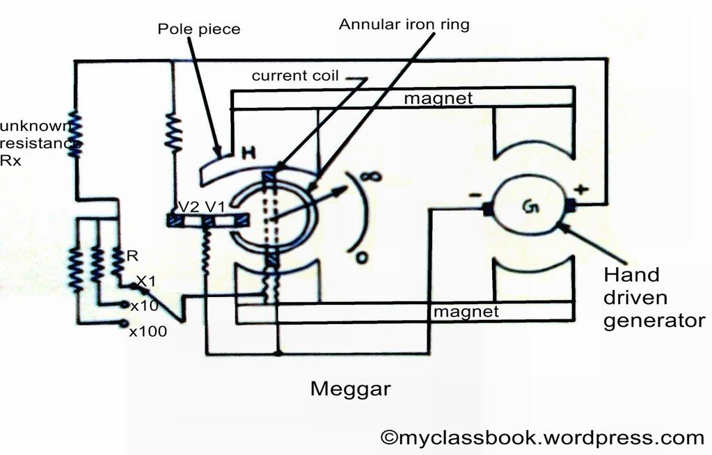
19 MEGGAR
20 A.C.Bridges A.C.Bridges are those circuits which are used to measure the unknown resistances, capacitance, inductance, frequency and mutual inductance.
21 R 1 R 4 R 1 R 3 = R 2 R4 R 2 R 3
22 Generalized Bridge configuration Z 1.Z 4 =Z 2.Z 3
23 Components of AC bridges Four arms A source of excitation For low frequency measurement power-line acts as a source. For higher frequencies electronic oscillators are used. Battery Balance Detector Head Phone250 Hz to 3-4 khz Vibration Galvanometer 5 Hz to 1000Hz. But used below 200 Hz. Tuneable amplifier detector 10 Hz to 100 khz
24 Measurement of self- inductance
25 Maxwell s inductance Bridge In the Maxwell s inductance bridge,there are two pure resistances used for balance relations but on other side or arms the two known impedances are used. The known impedances and the resistances make the unknown impedances as Z1 and Z2.Such a network is known as Maxwell s A.C.. Bridge. As shown in fig.
26 In the Maxwell s inductance bridge,there are two pure resistances used for balance relations but on other side or arms the two known impedances are used. The known impedances and the resistances make the unknown impedances as Z1 and Z2.Such a network is known as Maxwell s A.C.. Bridge. As shown in figure below-
27 Fig. (R1 + jwl1 )R3 = (R4 + jwl4 )R2
28 Phasor diagram
29 Maxwell s inductance and capacitance bridge
30 Phasor Diagram
31 Anderson Bridge In the Anderson Bridge the unknown inductance is measured in terms of a known capacitance and resistance. this method is capable of precise measurements of inductance over a wide range of values from a few micro-henrys to several henrys and is the best bridge method.
32
33 Phasor diagram
34 Hay s Bridge It is particularly useful if the phase angle of the inductive impedance is large. In this case a comparatively smaller series resistance R1 is used instead of a parallel résistance.( which has to be of a very large value) as shown in fig.
35 Fig L3= C1 R2 R4 R3= w C1 R1 R2 R4 1+w R1 C1 1+w R1 C1
36 Measurement of Capacitance
37 Capacitance Bridge We will consider only De Sauty bridge method of comparing two capacitances the bridge has maximum sensitivity when C2 = C3. The simplicity of this method is offset by the impossibility of obtaining a perfect balance if both the capacitors are not free from the dielectric loss. A perfect balance can only be obtained if air capacitors are used. as shown in fig.
38 Desauty Bridge C2= C3 R1 /R2
39 Phasor Diagram E3=E4=I2R4 I1R3 E1=E2=I1/WC1
40 Schering Bridge Schering bridge used for the measurement of capacitance and dielectric loss of a capacitor. It is a device for comparing an imperfect capacitor C2 in terms of a loss-free standard capacitor C1. As shown in fig.
41 Schering bridge
42 Phasor Diagram
43 Wien Parallel Bridge It is also a ratio bridge used mainly as the feedback network in the wide range audio-frequency R-C oscillators. It is may be used for the measurement of the audio-frequency but it is not as accurate as the modern digital frequency meters. As shown in fig.
44 Wien s bridge
45 Sources of Errors in Bridge Circuits Stray conductance Mutual Inductance Stray Capacitance Residues in components
46 Precaution and Techniques used for reducing Errors Use of High-quality Components Bridge Lay-out Sensitivity Stray Conductance Effects Eddy Current Errors Residual Errors Frequency and Waveform Errors
47 Wagner Earthing Device
Bridge Measurement 2.1 INTRODUCTION Advantages of Bridge Circuit
 2 Bridge Measurement 2.1 INTRODUCTION Bridges are often used for the precision measurement of component values, like resistance, inductance, capacitance, etc. The simplest form of a bridge circuit consists
CHAPTER 5 DC AND AC BRIDGE
 5. Introduction HAPTE 5 D AND A BIDGE Bridge circuits, which are instruments for making comparison measurements, are widely used to measure resistance, inductance, capacitance, and impedance. Bridge circuits
CHAPTER 5. BRIDGES AND THEIR APPLICATION Resistance Measurements. Dr. Wael Salah
 CHAPTER 5 BRIDGES AND THEIR APPLICATION Resistance Measurements 1 RESISTANCE MEASUREMENTS Conventional Ways of Measuring Resistance:- 1) Using a Ohmmeter Convenient but inaccurate, requires calibration
coil of the circuit. [8+8]
![coil of the circuit. [8+8]](/thumbs/80/81218867.jpg "coil of the circuit. [8+8]") Code No: R05310202 Set No. 1 III B.Tech I Semester Regular Examinations, November 2008 ELECTRICAL MEASUREMENTS (Electrical & Electronic Engineering) Time: 3 hours Max Marks: 80 Answer any FIVE Questions
Code No: R05310202 Set No. 1 III B.Tech I Semester Regular Examinations, November 2008 ELECTRICAL MEASUREMENTS (Electrical & Electronic Engineering) Time: 3 hours Max Marks: 80 Answer any FIVE Questions
Capacitor. Capacitor (Cont d)
") 1 2 1 Capacitor Capacitor is a passive two-terminal component storing the energy in an electric field charged by the voltage across the dielectric. Fixed Polarized Variable Capacitance is the ratio of
1 2 1 Capacitor Capacitor is a passive two-terminal component storing the energy in an electric field charged by the voltage across the dielectric. Fixed Polarized Variable Capacitance is the ratio of
Chapter 6.2 : A C Bridges for measurement of Capacitances and Inductances. Discipline Course-I
 Discipline Course-I Semester-II Paper No: Electricity and Magnetism Lesson: Chapter 6.2 : A C Bridges for measurement of Capacitances and Inductances Lesson Developer: Dr. Narmata Soni College/ Department:
Bridge Circuits. DR. GYURCSEK ISTVÁN Classic Electrical Measurements 3
 DR. GYURCSEK ISTVÁN Classic Electrical Measurements 3 Bridge Circuits Sources and additional materials (recommended) q I. Gyurcsek: Fundamentals of Electrical Measurements, PTE MIK 2018 (manuscript) q
ELECTRICAL MEASUREMENTS LAB MANUAL
 ELECTRICAL MEASUREMENTS LAB MANUAL Prepared by B.SAIDAMMA R13 Regulation Any 10 of the following experiments are to be conducted 1. Calibration and Testing of single phase energy Meter 2. Calibration of
ANDERSON S BRIDGE & SCHERING S BRIDGE
 ANDERSON S BRIDGE & SCHERING S BRIDGE ANDERSON S BRIDGE AIM: A)To measure inductance of a given coil by Anderson s bridge. B) To determine the value of a given capacitor and to obtain for its dissipation
QUESTION BANK DEPARTMENT OF ELECTRICAL AND ELECTRONICS ENGINEERING UNIT I - INTRODUCTION SYLLABUS
 QUESTION BANK DEPARTMENT OF ELECTRICAL AND ELECTRONICS ENGINEERING YEAR/SEM NAME OF THE SUBJECT NAME OF THE FACULTY : II / IV : EE6404 MEASUREMENTS AND INSTRUMENTATION : K.M.S.MUTHUKUMARA RAJAGURU, AP/EEE
INTC 1307 Instrumentation Test Equipment Teaching Unit 6 AC Bridges
 IHLAN OLLEGE chool of Engineering & Technology ev. 0 W. lonecker ev. (8/6/0) J. Bradbury INT 307 Instrumentation Test Equipment Teaching Unit 6 A Bridges Unit 6: A Bridges OBJETIVE:. To explain the operation
FACULTY OF ENGINEERING LAB SHEET. IM1: Wheatstone and Maxwell Wien Bridges
 FCULTY OF ENGINEEING LB SHEET EEL96 Instrumentation & Measurement Techniques TIMESTE 08-09 IM: Wheatstone and Maxwell Wien Bridges *Note: Please calculate the computed values for Tables. and. before the
Bridge Method. Bridge Method
 ridge Method EIE 240 Electrical and Electronic Measurement Class 7, March 13, 2015 1 ridge Method Diode bridge is an arrangement of four or more diodes for AC/DC full-wave rectifier. Component bridge methods
DC and AC Impedance of Reactive Elements
 3/6/20 D and A Impedance of Reactive Elements /6 D and A Impedance of Reactive Elements Now, recall from EES 2 the complex impedances of our basic circuit elements: ZR = R Z = jω ZL = jωl For a D signal
Sinusoidal Response of RLC Circuits
 Sinusoidal Response of RLC Circuits Series RL circuit Series RC circuit Series RLC circuit Parallel RL circuit Parallel RC circuit R-L Series Circuit R-L Series Circuit R-L Series Circuit Instantaneous
Resistance and Conductance
 1 2 1 Resistance and Conductance Resistance, R (Ohm ), is the tendency of a material to impede the flow of electric charges through it. The instantaneous voltage across a resistor is directly proportional
Measuring Properties of Piezoelectric Ceramics
 BULL.:SP-011 Measuring Properties of Piezoelectric Ceramics SPARKLER CERAMICS PVT. LTD. J - 508, MIDC, BHOSARI, PUNE - 411 026. INDIA. Tel : 91-20- 2747 2375, 2746 2956. Fax : 91-20 2746 2955 E-mail :
INSTITUTE OF AERONAUTICAL ENGINEERING (Autonomous) Dundigal, Hyderabad
 Dundigal, Hyderabad") INSTITUTE OF AERONAUTICAL ENGINEERING (Autonomous) Dundigal, Hyderabad - 500 04 ELECTRONICS AND COMMUNICATION ENGINEERING Name : Electronic Measurements and Instrumentation Code : A50422 Class : III -
INSTITUTE OF AERONAUTICAL ENGINEERING (Autonomous) Dundigal, Hyderabad - 500 04 ELECTRONICS AND COMMUNICATION ENGINEERING Name : Electronic Measurements and Instrumentation Code : A50422 Class : III -
INSTITUTE OF AERONAUTICAL ENGINEERING Dundigal, Hyderabad DEPARTMENT OF ECE QUESTION BANK. : G.Lakshminarayana, Asst.
 ` INSTITUTE OF AERONAUTICAL ENGINEERING Dundigal, Hyderabad - 500 04 DEPARTMENT OF ECE QUESTION BANK Name Code Class Branch P a g e : Electronic Measurements and Instrumentation : A504 : III - B. Tech
arxiv: v1 [physics.class-ph] 24 Apr 2008 Considerations for Anderson-Bridge Experiment P. Arun, Kuldeep Kumar & Mamta
![arxiv: v1 [physics.class-ph] 24 Apr 2008 Considerations for Anderson-Bridge Experiment P. Arun, Kuldeep Kumar & Mamta](/thumbs/90/103250595.jpg "arxiv: v1 [physics.class-ph] 24 Apr 2008 Considerations for Anderson-Bridge Experiment P. Arun, Kuldeep Kumar & Mamta") arxiv:0804.3932v1 [physics.class-ph] 24 Apr 2008 Considerations for Anderson-Bridge Experiment P. Arun, Kuldeep Kumar & Mamta Department of Physics and Electronics, S.G.T.B. Khalsa College University of
arxiv:0804.3932v1 [physics.class-ph] 24 Apr 2008 Considerations for Anderson-Bridge Experiment P. Arun, Kuldeep Kumar & Mamta Department of Physics and Electronics, S.G.T.B. Khalsa College University of
Code No: RR Set No. 1
 Code No: RR410209 Set No. 1 1. What are the gases mainly used in insulating medium at high pressures? Which is more suitable? Why? What about its dielectric strength? Explain. [16] 2. (a) Define time lags
Summary Notes ALTERNATING CURRENT AND VOLTAGE
 HIGHER CIRCUIT THEORY Wheatstone Bridge Circuit Any method of measuring resistance using an ammeter or voltmeter necessarily involves some error unless the resistances of the meters themselves are taken
ELECTRICITY AND MAGNETISM
 ELECTRICITY AND MAGNETISM Chapter 1. Electric Fields 1.1 Introduction 1.2 Triboelectric Effect 1.3 Experiments with Pith Balls 1.4 Experiments with a Gold-leaf Electroscope 1.5 Coulomb s Law 1.6 Electric
INSTITUTE OF AERONAUTICAL ENGINEERING (Autonomous) Dundigal, Hyderabad
 Dundigal, Hyderabad") INSTITUTE OF AERONAUTICAL ENGINEERING (Autonomous) Dundigal, Hyderabad - 500 043 ELECTRONICS AND COMMUNICATION ENGINEERING Course Name : Electronic Measurements and Instrumentation Course Code : A50422
INSTITUTE OF AERONAUTICAL ENGINEERING (Autonomous) Dundigal, Hyderabad - 500 043 ELECTRONICS AND COMMUNICATION ENGINEERING Course Name : Electronic Measurements and Instrumentation Course Code : A50422
Dept. of Electrical Engineering Final Exam, Summer Semester: 2014/2015
 de Form No. T611 Philadelphia University Faculty of Engineering Dept. of Electrical Engineering Final Exam, Summer Semester: 2014/2015 Student Name: Student Number: Course Title: nstrumentation and Measurement
PANDIAN SARASWATHI YADAV ENGINEERING COLLEGE DEPARTMENT OF ELECTRICAL AND ELECTRONICS ENGINEERING EE6404-MEASUREMENTS AND INSTRUMENTATION
 PANDIAN SARASWATHI YADAV ENGINEERING COLLEGE DEPARTMENT OF ELECTRICAL AND ELECTRONICS ENGINEERING EE6404-MEASUREMENTS AND INSTRUMENTATION ACADEMIC YEAR: 2015-2016 (EVEN SEMESTER) Branch: EEE QUESTION BANK
A free web support in Education. Internal resistance of the battery, r = 3 Ω. Maximum current drawn from the battery = I According to Ohm s law,
 Exercises Question 3.1: The storage battery of a car has an emf of 12 V. If the internal resistance of the battery is 0.4Ω, what is the maximum current that can be drawn from the battery? Answer 3.1: Emf
Sol: Semiconductor diode.
 48 49 1. What is the resistance value of a resistor of colour code Brown, Black, Red and silver? Sol: Brown-1, Black-0, Red-2, Silver- 10%. Resistance, R = 10 X 10-2 ±10Ω. 2. Mention a non-ohmic device.
NODIA AND COMPANY. GATE SOLVED PAPER Electrical Engineering ELECTRICAL & ELECTRONIC MEASUREMENTS. Copyright By NODIA & COMPANY
 No part of this publication may be reproduced or distributed in any form or any means, electronic, mechanical, photocopying, or otherwise without the prior permission of the author. GATE SOLVED PAPER Electrical
Conventional Paper-I Part A. 1. (a) Define intrinsic wave impedance for a medium and derive the equation for intrinsic vy
 Define intrinsic wave impedance for a medium and derive the equation for intrinsic vy") EE-Conventional Paper-I IES-01 www.gateforum.com Conventional Paper-I-01 Part A 1. (a) Define intrinsic wave impedance for a medium and derive the equation for intrinsic vy impedance for a lossy dielectric
EE-Conventional Paper-I IES-01 www.gateforum.com Conventional Paper-I-01 Part A 1. (a) Define intrinsic wave impedance for a medium and derive the equation for intrinsic vy impedance for a lossy dielectric
AC Circuits Homework Set
 Problem 1. In an oscillating LC circuit in which C=4.0 μf, the maximum potential difference across the capacitor during the oscillations is 1.50 V and the maximum current through the inductor is 50.0 ma.
Learnabout Electronics - AC Theory
 Learnabout Electronics - AC Theory Facts & Formulae for AC Theory www.learnabout-electronics.org Contents AC Wave Values... 2 Capacitance... 2 Charge on a Capacitor... 2 Total Capacitance... 2 Inductance...
CLASSROOM Classroom In this section of Resonance,
 Classroom In this section of Resonance, we invite readers to pose questions likely to be raised in a classroom situation. We may suggest strategies for dealing with them, or invite responses, or both.
Module 3 Electrical Fundamentals
 3.1 Electron Theory Structure and distribution of electrical charges within: atoms, molecules, ions, compounds; Molecular structure of conductors, semiconductors and insulators. 3.2 Static Electricity
Conventional Paper-I-2011 PART-A
 Conventional Paper-I-0 PART-A.a Give five properties of static magnetic field intensity. What are the different methods by which it can be calculated? Write a Maxwell s equation relating this in integral
ITL Public School First - Term( )
") Date: 9/09/6 ITL Public School First - Term(06-7) Class: XII Physics(04) Answer key Time: hrs M. M: 70 SECTION-A An ac source of voltage V =V 0 sin ωt is connected to an ideal capacitor. Draw graphs and
Date: 9/09/6 ITL Public School First - Term(06-7) Class: XII Physics(04) Answer key Time: hrs M. M: 70 SECTION-A An ac source of voltage V =V 0 sin ωt is connected to an ideal capacitor. Draw graphs and
To investigate further the series LCR circuit, especially around the point of minimum impedance. 1 Electricity & Electronics Constructor EEC470
 Series esonance OBJECTIE To investigate further the series LC circuit, especially around the point of minimum impedance. EQUIPMENT EQUIED Qty Apparatus Electricity & Electronics Constructor EEC470 Basic
ELEC ELE TRO TR MAGNETIC INDUCTION
 ELECTRO MAGNETIC INDUCTION Faraday Henry 1791-1867 1797 1878 Laws:- Faraday s Laws :- 1) When ever there is a change in magnetic flux linked with a coil, a current is generated in the coil. The current
EE 441: Advanced computer programming & Data Structures. L T P ESE: 100 Sessional 50 Laboratory: 50
 EE 441: Advanced computer programming & Data Structures L T P 3-2 3 ESE: 100 Sessional 50 Laboratory: 50 1. Review of 1st semester IC course: Control structure, decision control structure, case control
SHIVAJI UNIVERSITY, KOLHAPUR
 s Seat GROUP III 1. Transistor Series Voltage Regulator With a given rectifier, prepare a regulated power supply, using transistor. Vary output currents changing load resistance. Hence measure output voltages
ELECTRICAL & ELECTRONICS
 EE 326 (RR) Total No. of Questions :09] [Total No. of Pages : 02 III/IV B.Tech. DEGREE EXAMINATIONS, APRIL/MAY- 2017 Second Semester ELECTRICAL & ELECTRONICS ELECTRICAL MEASUREMENTS Time: Three Hours Answer
MUFFAKHAM JAH COLLEGE OF ENGINEERING & TECHNOLOGY. Banjara Hills Road No 3, Hyderabad 34. DEPARTMENT OF ELECTRICAL ENGINEERING
 MUFFAKHAM JAH COLLEGE OF ENGINEERING & TECHNOLOGY Banjara Hills Road No 3, Hyderabad 34 www.mjcollege.ac.in DEPARTMENT OF ELECTRICAL ENGINEERING LABORATORY MANUAL CIRCUITS AND MEASUREMENTS LAB For B.E.
1. Distinguish the important characteristics of instrument that are totally electrical and totally electronic in nature. [16]
![1. Distinguish the important characteristics of instrument that are totally electrical and totally electronic in nature. [16]](/thumbs/96/127822274.jpg "1. Distinguish the important characteristics of instrument that are totally electrical and totally electronic in nature. [16]") Code No: RR320204 Set No. 1 1. Distinguish the important characteristics of instrument that are totally electrical and totally electronic in nature. [16] 2. Distinguish between deterministic signals and
Code No: RR320204 Set No. 1 1. Distinguish the important characteristics of instrument that are totally electrical and totally electronic in nature. [16] 2. Distinguish between deterministic signals and
What s Your (real or imaginary) LCR IQ?
 LCR IQ?") Chroma Systems Solutions, Inc. What s Your (real or imaginary) LCR IQ? 11021, 11025 LCR Meter Keywords:. Impedance, Inductance, Capacitance, Resistance, Admittance, Conductance, Dissipation Factor, 4-Terminal
Chroma Systems Solutions, Inc. What s Your (real or imaginary) LCR IQ? 11021, 11025 LCR Meter Keywords:. Impedance, Inductance, Capacitance, Resistance, Admittance, Conductance, Dissipation Factor, 4-Terminal
PRE-BOARD EXAMINATION STD : XII MARKS : 150
 PRE-BOARD EXAMINATION STD : XII MARKS : 150 SUB : PHYSICS TIME : 3.00 Hrs I.Choose the correct answer: 30x1=30 1.Which of the following quantities not a scalar? a)electric flux b) electric potential c)
Alternating Current Circuits
 Alternating Current Circuits AC Circuit An AC circuit consists of a combination of circuit elements and an AC generator or source. The output of an AC generator is sinusoidal and varies with time according
The secondary winding have equal no. of turns. The secondary windings are placed identically on either side of the primary winding.
 UNIT 4 DISPLACEMENT MEASURMENT Electrical comparator Working principle of Electrical comparators: These instruments are based on the theory of Wheatstone A.C. Bridge. When the bridge is electrically balanced,
ELECTROMAGNETIC INDUCTION
 ELECTROMAGNETIC INDUCTION 1. Magnetic Flux 2. Faraday s Experiments 3. Faraday s Laws of Electromagnetic Induction 4. Lenz s Law and Law of Conservation of Energy 5. Expression for Induced emf based on
Get Discount Coupons for your Coaching institute and FREE Study Material at ELECTROMAGNETIC INDUCTION
 ELECTROMAGNETIC INDUCTION 1. Magnetic Flux 2. Faraday s Experiments 3. Faraday s Laws of Electromagnetic Induction 4. Lenz s Law and Law of Conservation of Energy 5. Expression for Induced emf based on
ELECTROMAGNETIC OSCILLATIONS AND ALTERNATING CURRENT
 Chapter 31: ELECTROMAGNETIC OSCILLATIONS AND ALTERNATING CURRENT 1 A charged capacitor and an inductor are connected in series At time t = 0 the current is zero, but the capacitor is charged If T is the
EXPERIMENT 07 TO STUDY DC RC CIRCUIT AND TRANSIENT PHENOMENA
 EXPERIMENT 07 TO STUDY DC RC CIRCUIT AND TRANSIENT PHENOMENA DISCUSSION The capacitor is a element which stores electric energy by charging the charge on it. Bear in mind that the charge on a capacitor
1. DE-SAUTY BRIDGE DEV
 1. DE-SAUTY BRIDGE Object: To determine the capacitance of two capacitors by De-Sauty bridge. Apparatus Used: De-Sauty bridge, connecting wire, Head phone. Formula Used: The following formula is used for
Lecture 9 Time Domain vs. Frequency Domain
 . Topics covered Lecture 9 Time Domain vs. Frequency Domain (a) AC power in the time domain (b) AC power in the frequency domain (c) Reactive power (d) Maximum power transfer in AC circuits (e) Frequency
Unit 3 Transducers. Lecture_3.1 Introduction to Transducers
 Unit 3 Transducers Lecture_3.1 Introduction to Transducers Introduction to transducers A transducer is a device that converts one form of energy to other form. It converts the measurand to a usable electrical
Outline of College Physics OpenStax Book
 Outline of College Physics OpenStax Book Taken from the online version of the book Dec. 27, 2017 18. Electric Charge and Electric Field 18.1. Static Electricity and Charge: Conservation of Charge Define
ASSOCIATE DEGREE IN ENGINEERING TECHNOLOGY RESIT EXAMINATIONS SEMESTER 2 JUNE 2011
 ASSOCIATE DEGREE IN ENGINEERING TECHNOLOGY RESIT EXAMINATIONS SEMESTER 2 JUNE 2011 COURSE NAME: PHYSICS 2 CODE: GROUP: ADET 1 DATE: JUNE 29 TIME: 1:00 DURATION: 2 HOUR INSTRUCTIONS: 1. This paper consists
Power Factor Improvement
 Salman bin AbdulazizUniversity College of Engineering Electrical Engineering Department EE 2050Electrical Circuit Laboratory Power Factor Improvement Experiment # 4 Objectives: 1. To introduce the concept
AE60 INSTRUMENTATION & MEASUREMENTS DEC 2013
 Q.2 a. Differentiate between the direct and indirect method of measurement. There are two methods of measurement: 1) direct comparison with the standard, and 2) indirect comparison with the standard. Both
Electrical Circuits Lab Series RC Circuit Phasor Diagram
 Electrical Circuits Lab. 0903219 Series RC Circuit Phasor Diagram - Simple steps to draw phasor diagram of a series RC circuit without memorizing: * Start with the quantity (voltage or current) that is
V, I, R measurements: how to generate and measure quantities and then how to get data (resistivity, magnetoresistance, Hall). Makariy A.
. Makariy A.") V, I, R measurements: how to generate and measure quantities and then how to get data (resistivity, magnetoresistance, Hall). 590B Makariy A. Tanatar November 10, 2008 SI units/history Resistivity Typical
V, I, R measurements: how to generate and measure quantities and then how to get data (resistivity, magnetoresistance, Hall). 590B Makariy A. Tanatar November 10, 2008 SI units/history Resistivity Typical
ELECTRO MAGNETIC INDUCTION
 ELECTRO MAGNETIC INDUCTION 1) A Circular coil is placed near a current carrying conductor. The induced current is anti clock wise when the coil is, 1. Stationary 2. Moved away from the conductor 3. Moved
EE 242 EXPERIMENT 8: CHARACTERISTIC OF PARALLEL RLC CIRCUIT BY USING PULSE EXCITATION 1
 EE 242 EXPERIMENT 8: CHARACTERISTIC OF PARALLEL RLC CIRCUIT BY USING PULSE EXCITATION 1 PURPOSE: To experimentally study the behavior of a parallel RLC circuit by using pulse excitation and to verify that
Chapter 32A AC Circuits. A PowerPoint Presentation by Paul E. Tippens, Professor of Physics Southern Polytechnic State University
 Chapter 32A AC Circuits A PowerPoint Presentation by Paul E. Tippens, Professor of Physics Southern Polytechnic State University 2007 Objectives: After completing this module, you should be able to: Describe
e453.eps 1 Change (or the absolute value) in the measured physical variable 2 Change in the sensor property is translated into low-power-level
 in the measured physical variable 2 Change in the sensor property is translated into low-power-level") 3 Basic Phenomenon in Effect in Sensor Operation Sensors Prof. Dr. M. Zahurul Haq zahurul@me.buet.ac.bd http://teacher.buet.ac.bd/zahurul/ Department of Mechanical Engineering Bangladesh University of
3 Basic Phenomenon in Effect in Sensor Operation Sensors Prof. Dr. M. Zahurul Haq zahurul@me.buet.ac.bd http://teacher.buet.ac.bd/zahurul/ Department of Mechanical Engineering Bangladesh University of
Assessment Schedule 2015 Physics: Demonstrate understanding of electrical systems (91526)
") NCEA Level 3 Physics (91526) 2015 page 1 of 6 Assessment Schedule 2015 Physics: Demonstrate understanding of electrical systems (91526) Evidence Q Evidence Achievement Achievement with Merit Achievement
NCEA Level 3 Physics (91526) 2015 page 1 of 6 Assessment Schedule 2015 Physics: Demonstrate understanding of electrical systems (91526) Evidence Q Evidence Achievement Achievement with Merit Achievement
Higher Physics. Electricity. Summary Notes. Monitoring and measuring a.c. Current, potential difference, power and resistance
 Higher Physics Electricity Summary Notes Monitoring and measuring a.c. Current, potential difference, power and resistance Electrical sources and internal resistance Capacitors Conductors, semiconductors
Electronics Prof. D C Dube Department of Physics Indian Institute of Technology Delhi
 Electronics Prof. D C Dube Department of Physics Indian Institute of Technology Delhi Module No. 07 Differential and Operational Amplifiers Lecture No. 39 Summing, Scaling and Averaging Amplifiers (Refer
Single Phase Parallel AC Circuits
 Single Phase Parallel AC Circuits 1 Single Phase Parallel A.C. Circuits (Much of this material has come from Electrical & Electronic Principles & Technology by John Bird) n parallel a.c. circuits similar
Physics (Theory) There are 30 questions in total. Question Nos. 1 to 8 are very short answer type questions and carry one mark each.
 There are 30 questions in total. Question Nos. 1 to 8 are very short answer type questions and carry one mark each.") Physics (Theory) Time allowed: 3 hours] [Maximum marks:70 General Instructions: (i) All questions are compulsory. (ii) (iii) (iii) (iv) (v) There are 30 questions in total. Question Nos. 1 to 8 are very
Physics (Theory) Time allowed: 3 hours] [Maximum marks:70 General Instructions: (i) All questions are compulsory. (ii) (iii) (iii) (iv) (v) There are 30 questions in total. Question Nos. 1 to 8 are very
The simplest type of alternating current is one which varies with time simple harmonically. It is represented by
 ALTERNATING CURRENTS. Alternating Current and Alternating EMF An alternating current is one whose magnitude changes continuously with time between zero and a maximum value and whose direction reverses
Biosensors and Instrumentation: Tutorial 2
 Biosensors and Instrumentation: Tutorial 2. One of the most straightforward methods of monitoring temperature is to use the thermal variation of a resistor... Suggest a possible problem with the use of
Electricity and Light Pre Lab Questions
 Electricity and Light Pre Lab Questions The pre lab questions can be answered by reading the theory and procedure for the related lab. You are strongly encouraged to answers these questions on your own.
Mise en pratique for the definition of the ampere and other electric units in the SI
 Mise en pratique for the definition of the ampere and other electric units in the SI Consultative Committee for Electricity and Magnetism 1. Introduction The purpose of this Mise en pratique, prepared
University of the Philippines College of Science PHYSICS 72. Summer Second Long Problem Set
 University of the Philippines College of Science PHYSICS 72 Summer 2012-2013 Second Long Problem Set INSTRUCTIONS: Choose the best answer and shade the corresponding circle on your answer sheet. To change
CBSE Board Class XII Physics Set 1 Board Paper Time: 3 hours [Total Marks: 70]
![CBSE Board Class XII Physics Set 1 Board Paper Time: 3 hours [Total Marks: 70]](/thumbs/95/124107521.jpg "CBSE Board Class XII Physics Set 1 Board Paper Time: 3 hours [Total Marks: 70]") CBSE Board Class XII Physics Set 1 Board Paper - 2009 Time: 3 hours [Total Marks: 70] General instructions: 1. All questions are compulsory. 2. There are 30 questions in total. Questions 1 to 8 are very
CBSE Board Class XII Physics Set 1 Board Paper - 2009 Time: 3 hours [Total Marks: 70] General instructions: 1. All questions are compulsory. 2. There are 30 questions in total. Questions 1 to 8 are very
CLUSTER LEVEL WORK SHOP
 CLUSTER LEVEL WORK SHOP SUBJECT PHYSICS QUESTION BANK (ALTERNATING CURRENT ) DATE: 0/08/06 What is the phase difference between the voltage across the inductance and capacitor in series AC circuit? Ans.
PHYSICS ASSIGNMENT ES/CE/MAG. Class XII
 PHYSICS ASSIGNMENT ES/CE/MAG Class XII MM : 70 1. What is dielectric strength of a medium? Give its value for vacuum. 1 2. What is the physical importance of the line integral of an electrostatic field?
Trek electrostatic voltmeters Setup, environment, working conditions
 Dr. Maciej A. Noras 1 Introduction Abstract An analysis of basic sources of errors for electrostatic voltmeter measurements is presented. Stray capacitance and synchronous noise pickup are identified as
FIRST TERM EXAMINATION (07 SEPT 2015) Paper - PHYSICS Class XII (SET B) Time: 3hrs. MM: 70
 Paper - PHYSICS Class XII (SET B) Time: 3hrs. MM: 70") FIRST TERM EXAMINATION (07 SEPT 205) Paper - PHYSICS Class XII (SET B) Time: 3hrs. MM: 70 Instructions:. All questions are compulsory. 2. Q.no. to 5 carry mark each. 3. Q.no. 6 to 0 carry 2 marks each.
FIRST TERM EXAMINATION (07 SEPT 205) Paper - PHYSICS Class XII (SET B) Time: 3hrs. MM: 70 Instructions:. All questions are compulsory. 2. Q.no. to 5 carry mark each. 3. Q.no. 6 to 0 carry 2 marks each.
PHYSICS : CLASS XII ALL SUBJECTIVE ASSESSMENT TEST ASAT
 PHYSICS 202 203: CLASS XII ALL SUBJECTIVE ASSESSMENT TEST ASAT MM MARKS: 70] [TIME: 3 HOUR General Instructions: All the questions are compulsory Question no. to 8 consist of one marks questions, which
General Physics (PHY 2140)
") General Physics (PHY 2140) Lecture 10 6/12/2007 Electricity and Magnetism Induced voltages and induction Self-Inductance RL Circuits Energy in magnetic fields AC circuits and EM waves Resistors, capacitors
General Physics (PHY 2140) Lecture 10 6/12/2007 Electricity and Magnetism Induced voltages and induction Self-Inductance RL Circuits Energy in magnetic fields AC circuits and EM waves Resistors, capacitors
Physics (2) Laboratory manual
 Laboratory manual") PHYS 104 Laboratory Physics (2) Laboratory manual Dr. Chokri Belgacem, Dr. Yazid Delenda, Dr. Magdi Hasan Department of Physics, Faculty of Sciences and Arts at Yanbu, Taibah University - Yanbu Branch,
PHYS 104 Laboratory Physics (2) Laboratory manual Dr. Chokri Belgacem, Dr. Yazid Delenda, Dr. Magdi Hasan Department of Physics, Faculty of Sciences and Arts at Yanbu, Taibah University - Yanbu Branch,
CBSE QUESTION PAPER. PHYSICS (Theory)
") CBSE QUESTION PAPER PHYSICS (Theory) Time allowed : 3 hours Maximum Marks : 70 General Instructions: (i) (ii) (iii) All questions are compulsory. There are 30 questions in total. Questions 1 to 8 carry
CBSE QUESTION PAPER PHYSICS (Theory) Time allowed : 3 hours Maximum Marks : 70 General Instructions: (i) (ii) (iii) All questions are compulsory. There are 30 questions in total. Questions 1 to 8 carry
MAY/JUNE 2006 Question & Model Answer IN BASIC ELECTRICITY 194
 MAY/JUNE 2006 Question & Model Answer IN BASIC ELECTRICITY 194 Question 1 (a) List three sources of heat in soldering (b) state the functions of flux in soldering (c) briefly describe with aid of diagram
Handout 11: AC circuit. AC generator
 Handout : AC circuit AC generator Figure compares the voltage across the directcurrent (DC) generator and that across the alternatingcurrent (AC) generator For DC generator, the voltage is constant For
 TELANGANA/ANDHRA PRADESH TRANSCO/GENCO/DISCUM Assistant Engineer Examination ELECTRICAL ENGINEERING (Previous Paper 7) AP TRANSCO - AP GENCO-AE QUESTION PAPER 1. In two wattmeter method of 3-phase power
Physics 2020 Exam 2 Constants and Formulae
 Physics 2020 Exam 2 Constants and Formulae Useful Constants k e = 8.99 10 9 N m 2 /C 2 c = 3.00 10 8 m/s ɛ = 8.85 10 12 C 2 /(N m 2 ) µ = 4π 10 7 T m/a e = 1.602 10 19 C h = 6.626 10 34 J s m p = 1.67
Basics of Network Theory (Part-I)
") Basics of Network Theory (PartI). A square waveform as shown in figure is applied across mh ideal inductor. The current through the inductor is a. wave of peak amplitude. V 0 0.5 t (m sec) [Gate 987: Marks]
Basics of Network Theory (PartI). A square waveform as shown in figure is applied across mh ideal inductor. The current through the inductor is a. wave of peak amplitude. V 0 0.5 t (m sec) [Gate 987: Marks]
 Alternating Currents. The power is transmitted from a power house on high voltage ac because (a) Electric current travels faster at higher volts (b) It is more economical due to less power wastage (c)
Solved Problems. Electric Circuits & Components. 1-1 Write the KVL equation for the circuit shown.
 Solved Problems Electric Circuits & Components 1-1 Write the KVL equation for the circuit shown. 1-2 Write the KCL equation for the principal node shown. 1-2A In the DC circuit given in Fig. 1, find (i)
Chapter 30 Examples : Inductance (sections 1 through 6) Key concepts: (See chapter 29 also.)
 Key concepts: (See chapter 29 also.)") Chapter 30 Examples : Inductance (sections 1 through 6) Key concepts: (See chapter 29 also.) ξ 2 = MdI 1 /dt : A changing current in a coil of wire (1) will induce an EMF in a second coil (2) placed nearby.
Chapter 30 Examples : Inductance (sections 1 through 6) Key concepts: (See chapter 29 also.) ξ 2 = MdI 1 /dt : A changing current in a coil of wire (1) will induce an EMF in a second coil (2) placed nearby.
EDEXCEL NATIONALS UNIT 5 - ELECTRICAL AND ELECTRONIC PRINCIPLES. ASSIGNMENT No.2 - CAPACITOR NETWORK
 EDEXCEL NATIONALS UNIT 5 - ELECTRICAL AND ELECTRONIC PRINCIPLES ASSIGNMENT No.2 - CAPACITOR NETWORK NAME: I agree to the assessment as contained in this assignment. I confirm that the work submitted is
Review of Basic Electrical and Magnetic Circuit Concepts EE
 Review of Basic Electrical and Magnetic Circuit Concepts EE 442-642 Sinusoidal Linear Circuits: Instantaneous voltage, current and power, rms values Average (real) power, reactive power, apparent power,
Assessment Schedule 2016 Physics: Demonstrate understanding electrical systems (91526)
") NCEA evel 3 Physics (91526) 2016 page 1 of 5 Assessment Schedule 2016 Physics: Demonstrate understanding electrical systems (91526) Evidence Statement NØ N1 N 2 A 3 A 4 M 5 M 6 E 7 E 8 0 1A 2A 3A 4A or
NCEA evel 3 Physics (91526) 2016 page 1 of 5 Assessment Schedule 2016 Physics: Demonstrate understanding electrical systems (91526) Evidence Statement NØ N1 N 2 A 3 A 4 M 5 M 6 E 7 E 8 0 1A 2A 3A 4A or
CIRCULAR MOTION GRAVITATION ROTATIONAL MOTION
 PHYSICS I & II List of Definitions and Laws / Principles 1. Angular Displacement 2. Right Hand Rule and Right Hand Screw Rule 3. Angular Velocity 4. Angular Acceleration 5. Uniform Circular Motion (U.C.M.)
Chapter 1 - Basic Concepts. Measurement System Components. Sensor - Transducer. Signal-conditioning. Output. Feedback-control
 Chapter 1 - Basic Concepts Measurement System Components Sensor - Transducer Signal-conditioning Output Feedback-control MeasurementSystemConcepts.doc 8/27/2008 12:03 PM Page 1 Example: Sensor/ Transducer
UNIT II CURRENT ELECTRICITY
 UNIT II CUENT ELECTICITY Weightage : 07 Marks Electric current; flow of electric charges in a metllic conductor, drift velocity, mobility and their relation with electric current. Ohm s law electrical
Chapter 1: Electrostatics
 1.1 Coulomb s law a) State Coulomb s law, Chapter 1: Electrostatics b) Sketch the electric force diagram and apply Coulomb s law for a system of point charges. 1.2 Electric field a) Define and use electric
RADIO AMATEUR EXAM GENERAL CLASS
 RAE-Lessons by 4S7VJ 1 CHAPTER- 2 RADIO AMATEUR EXAM GENERAL CLASS By 4S7VJ 2.1 Sine-wave If a magnet rotates near a coil, an alternating e.m.f. (a.c.) generates in the coil. This e.m.f. gradually increase
PHYS 241 EXAM #2 November 9, 2006
 1. ( 5 points) A resistance R and a 3.9 H inductance are in series across a 60 Hz AC voltage. The voltage across the resistor is 23 V and the voltage across the inductor is 35 V. Assume that all voltages